Multi-stage Centrifugal Compressor Modifications and Rerates

Case – 10 Single Stage Centrifugal Compressor
Copy Right By: Thomas T.S. Wan (温到祥)
Nov. 13, 2011 All Rights Reserved
Case Background: This case is to exam the performance of a single stage centrifugal compressor and to show how to use the performance map to familiar the characteristics of the centrifugal compressor. The operating conditions proposed for the compressor is shown below:
Capacity: 1,020 TR. Refrigerant: R-134a Evaporative Temperature: 36°F Condensing Temperature: 106°F Suction piping loss: 1.2 Psi Suction line superheat: 2°F Discharge Piping Loss: 2.3 Psi Input speed: 2,950 RPM. Impeller Diameter of KA-65: D =14.1”
Use the information shown in the section of Related Technical Data and Engineering Information for the Case, make a calculation to see if the TR is optimized to the compressor; if not, change the TR (all other data unchanged) that is more or less suitable for the compressor. Derive the answer from the calculation for the following questions:
A. Are the operating conditions OK for the compressor? If not, what is the
maximum TR suitable for the compressor? B. What is the running Mach number? C. Compressor Speed at the design point. D. Adiabatic Efficiency. E. Compressor Speed Code selected. F. Power Consumption at design full load. G. What is the approximate surge capacity (% of partial load), if the
compressor is operating at constant head.

Related Technical Data and Engineering Information for the Case:
Figure 10-1 Typical Performance Map for KA-65 Centrifugal Compressor
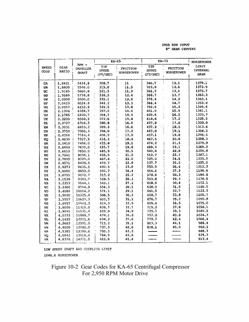
Figure 10-2 Gear Codes for KA-65 Centrifugal Compressor For 2,950 RPM Motor Drive

Cogitation Compressor calculation:
Recap the operating conditions: Capacity: 1,020 TR. Refrigerant: R-134a Evaporative Temperature: 36°F Condensing Temperature: 106°F Suction piping loss: 1.2 Psi Suction line superheat: 2°F Discharge Piping Loss: 2.3 Psi Input speed: 2,950 RPM.
Compressor discharge and suction conditions:
Discharge Pressure = 152.03 + 2.3
= 154.33 Psia Suction Pressure = 46.02 – 1.2
= 44.82 Psia
Suction Temperature = 36 + 3 = 38°F
Compressor Suction Conditions: 44.82 Psia, 38°F
Refrigeration Load = 1,020 TR

Figure 10-3 P-H Diagram for the Case The operating point for the compressor is determined by the factors of Θ and Ω.
200 Flow, Lbs/Min = --------------------------- x TR
Refrigeration Effect
200 = -------------------------- x 1020 107.75 – 47.00
= 3,358.03 Lbs/Min.
ACFM = (Lbs/Min) x Vg
= 3,358.03 x 1.0579 = 3,552.46 ACFM
D2 = (14.1)² = 198.81
Va = 483.54 Ft/Sec.

Head = (119.45 – 108.30) x 778 = 8,674.70 Ft.
ACFM x 2.4 Θ = -------------------------
Va x D2
3552.46 x 2.4 = ------------------------- 483.54 x 198.81
= 0.0887
Head x 32.2 Ω = --------------------------------
Va2
8674.70 x 32.2 = ------------------------------- (483.54)2
= 1.195 From the Compressor Map Figure 10-1, at Θ = 0.0887 Ω = 1.195 Obtain the Mach number and the compressor efficiency:
Mo = 1.408 Eff = 79.6%
From the formula: Ts Mo = ------- Va Compressor design speed required to generate the Mach number:
Ts = Mo x Va
= 1.408 x 483.54 = 680.8 Ft./Sec.

Figure 10-1A Operating Points for KA-65 Compressor

Figure 10-2A Gear Code Selections for the Compressor Note: Compressor efficiency and part load performance can be improved by changing
the impeller profile design. Ask the compressor manufacturer for a better energy consumption selection for energy conservation application.

From the chart of Figure 10-2, for KA-65 compressor at Ts = 694.2 Ft/Sec. Select Gear Code VL, Compressor Speed = 12,221.6 RPM FHP = 37.6 HP Compressor Power Consumption:
Flow x Head 3358.03 x 8674.70 GHP = ------------------- = ----------------------------- 33000 x Eff 33000 x 0.796
= 1,109.0 HP SHP = GHP + FHP = 1,109.0 + 37.6 = 1,145.2 HP Check Limitations: From Figure 10-2 at Ts = 694.2 Ft/Sec. Maximum HP limit for Internal Gear for Gear Code VL is 1,006.4 HP Maximum HP limit for low speed shaft and the coupling is 1,046.6 HP The SHP exceeds both Internal Gear limitation; the Low Speed Shaft and Coupling limits, therefore the selection is no good. Try to reduce the TR while to maintain all other operating conditions not changed. Try to reduce the cooling load to 900 TR: 200 Flow, Lbs/Min = --------------------------- x TR
Refrigeration Effect
200 = -------------------------- x 900 107.75 – 47.00
= 2,962.97 Lbs/Min.
ACFM = (Lbs/Min) x Vg
= 2,962.97 x 1.0579 = 3,134.52 ACFM

D2 = (14.1)² = 198.81
Va = 483.54 Ft/Sec.
Head = (119.45 – 108.30) x 778 = 8,674.70 Ft.
ACFM x 2.4 Θ = -------------------------
Va x D2
3134.52 x 2.4 = ------------------------- 483.54 x 198.81
= 0.0783
Head x 32.2 Ω = --------------------------------
Va2
8674.70 x 32.2 = ------------------------------- (483.54)2
= 1.195 From the Compressor Map Figure 10-1A, at Θ = 0.0783 Ω = 1.195
Mo = 1.385 Eff = 79.86%
Ts Mo = ------- Va
Ts = Mo x Va = 1.385 x 483.54 = 669.7 Ft./Sec. From Figure 10-2A:

Select Gear Code VK, Ts = 674.1 Ft/Sec. Compressor Speed 11,868.7 RPM FHP = 36.2 HP Power Consumption Calculation:
Flow x Head 2962.97 x 8674.70 GHP = ------------------- = ----------------------------- 33000 x Eff 33000 x 0.7986
= 975.3 HP SHP = GHP + FHP = 975.3 + 36.2 = 1,011.5 HP Check Limitations: Maximum HP limit for Internal Gear for Gear Code VK is 1,024.3 HP Maximum HP limit for low speed shaft and the coupling is 1,046.6 HP Selection OK, use 900 TR instead of 1,020 TR Surge Point at constant head θ = 0.0735 0.0735 Percent Partial Load = --------------- = 94% 0.0783 Conclusion: A. 900 TR is recommended. B. Operating Mach number: Mo = 1.385. C. Adiabatic efficiency: Eff = 79.86% D. Speed Code selected: VK E. Compressor Speed: 11,868,7 RPM F. Power Consumption at full load: 1,011.5 HP. G. Surge point at constant head: 94%