Car parks in steel - ArcelorMittalsections.arcelormittal.com/.../Carpark/CarParks_EN.pdf · Car...
32
Car parks in steel ArcelorMittal Europe - Long Products Sections and Merchant Bars
Transcript of Car parks in steel - ArcelorMittalsections.arcelormittal.com/.../Carpark/CarParks_EN.pdf · Car...

Car parks in steel
ArcelorMittal Europe - Long ProductsSections and Merchant Bars

EconomicalSustainableSafe
Contents
1. Car park design 2
2. Car park layout 7
3. Suitable car park steel structures 15
4. Corrosion and fire protection of steel structures 21
5. Durability of steel structures 25
Technical assistance & finishing 28
Your partners 29
1


3
1. CAR PARK DESIGN 1.1 Introduction 41.2 Advantages of steel structures 51.3 Architectural design 5

1. Car park design
In the construction of multi-storey car parks, the idea of profitability is essential and covers a number of aspects. Steel construction makes it possible to:
l reduce construction costsl optimise the occupation of the car parkl improve return on investment by
gaining floor area (in m2)
Cost of construction
The average construction cost of a multi-storey car park is about 5 000 euro per parking space (¤/p). Using very economical construction methods, this figure can be reduced to 3 000 ¤/p. The local conditions, the extent of the additional installations, improved comfort and aesthetic aspects can increase these amounts up to 10 000 ¤/p.
Optimising the occupation
A profitable multi-storey car park must have a high occupation rate. This can only be achieved with high quality building materials and ease of use in mind. Increased storey heights, wide ramps, slim columns and high quality fittings increase the user’s comfort and safety.
1.1 Introduction
Profitability analysis
All costs connected with the construction and operation of the car park until the end of its useful life must be taken into account. They include the building costs, the time of construction, the operating costs and the parking fees.
Profitability analyses show that steel framed structures are by far the most economical. Mainly the high degree of prefabrication allows very short construction times, thus resulting in early return on invest.
Short notice changes in stated needs and requirements to the building as well as variable operational life spans tend to reduce the flexibility during the design phase. It is therefore essential to give the greatest attention to the adaptability of the structure.
Steel structures in car parks are flexible and allow to easily adapt the size of the building to new needs without generally disturbing the operations within. Provided an appropriate design, steel structures can also be dismantled after a given period of time for reconstruction at a new site.
Furthermore, it is appropriate to examine in each case the economical impact of ancillary services, such as petrol stations with servicing and car wash facilities, newspaper kiosks, etc.
These additional features contribute to the attractiveness of the project and generate additional income, thus improving overall profitability.

5
The advantages of steel structures, namely:
l reduced weight of the structurel insensitivity to settlementsl elastic deformation behaviourl hinged simple supports
result in simplified flat foundations. They also may make deep foundations unnecessary.
In case very weak subsoils require deep foundations for controlling the settlements, the design of lightweight steel structures leads to reduced pile lengths.
It is a good procedure to wait with the tender until the type of bearing structure is fixed in order to take full advantage of the reduced costs of foundations associated with light steel structures.
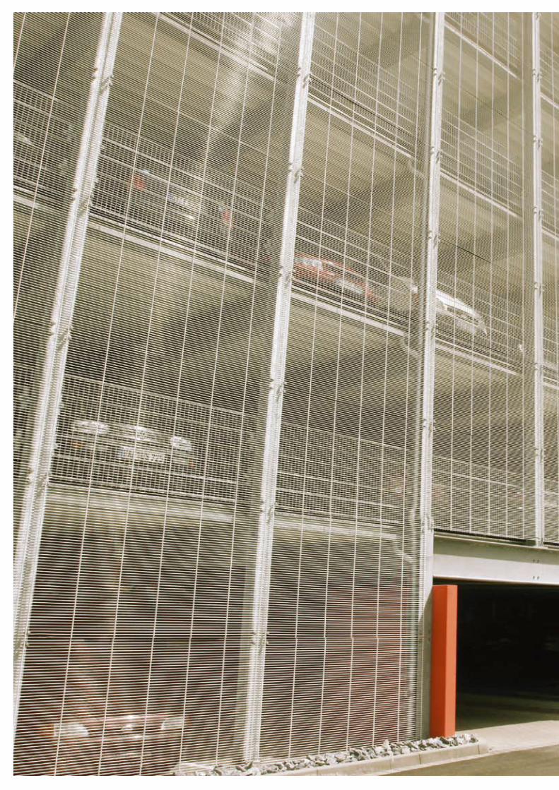
When designing the façade of a multi-storey car park, a major part of the outside walls should remain open (pic. 1.3.2).
The design of the façade is used by the architect to make the building fit perfectly in the urban landscape. The use of oblique strips, inclined panels, glazed or perforated units etc. help to break the monotony of prefabricated buildings.
Many practical examples of multi-storey car parks are proof of a successful integration of the building in the surrounding environment.
When defining the layout of a car park, it is good practice to keep the access lanes as short as possible and to reduce the area occupied by the ramps as much as possible.
1.2 Advantages of steel structures
1.3 Architectural design
1.3.2


7
2. CAR PARK LAyout2.1 How to optimise car park layout ? 82.2 How to optimize parking space ? 112.3 Which loads are applicable in car park design ? 12

2. Car park layout
The ramp arrangement depends on the type of car park. In this respect, a distinction is made between the duration of occupation (continuous, short or long stay parking) and the period of occupation (intermittent or continuous).
The ramps are located inside or outside the building and can be curved or straight. Helical ramps allow faster traffic than straight ramps. The parking access lanes must run along the parking spaces. Distances in the exit direction should be as short as possible.
The ramp slope must be less than 15%, ideally below 12%. The slopes of external ramps should be even lower unless appropriate anti-icing measures are taken in winter. A small slope results of course in longer ramps and greater required surface area. On the other hand, wider ramps with gentle slopes add to the comfort of use, an important factor to be considered during design.
Car parks with a low overall height and with low storey heights make it possible to shorten the ramps. Another way of reducing ramp lengths while maintaining reasonable slopes is to use the Humy system in which adjacent parking aisles are offset in height by half a storey (fig. 2.1.1).
2.1 How to optimise car park layout?
2.1.1

9
2. Car park layout
When the floors are arranged vertically without overlap, this system requires a minimum width of 31 m. For each of the ramp types illustrated (fig. 2.1.2), table 2.1.3 shows the required space and the distances for entry and exit routes of a 4-storey building designed according to the Humy system.
Another project of the same capacity and intermittent occupation shows the performance of an arrangement with external helical ramps. Here, larger area requirements and a more complex construction have however to be taken into account.
2.1.1 Humy system without and with overlap of half-storeys. 2.1.2 Ramp arrangement2.1.3 Comparison of entry and exit distances for the ramp arrangements acc. to figure 2.1.2 (car park with 4 levels or 8 half-levels)
2.1.3
Ramp
arrangement
Total area
of each
level
[m2]
Number
of spaces
per level
Floor
area per
parking
space
[m2]
Distances
A 2 248 100 22,48 654 521
B 2 170 100 21,70 673 599
C 2 248 102 22,03 514 271
D 2 248 100 22,48 654 271
E 2 889 100 28,89 316 251
Entry [m]
Exit[m]
2.1.2
B: ramps at the ends of the building with traffic in both directions
5,00 10,00 7,50 5,00
2,50
5,0
05
,00
5,5
05
,50
10
,00
45,00
72,50
31
,00
A: entry and exit ramps adjacent, at the ends of the building, one-way traffic
5,00 5,00 5,00 5,00
5,0
05
,00
5,5
05
,50
10
,00
52,50
72,50
31
,00
C: entry and exit traffic separated, exit route shortened
7,50 7,50
5,0
05
,00
5,5
05
,50
10
,00
55,00
70,00
31
,00
2,50
D: entry and exit traffic mixed, exit route shortened
5,00 5,0022,50 5,0020,00
5,0
05
,00
5,5
05
,50
10
,00
10,00 5,00
72,50
31
,00
2,50
E: helical ramps on the outside of the building
7,50
4,7
021
,40
3,5
0
7,50
5,0
05
,00
5,5
05
,50
10
,00
55,00
70,00~20,00
31
,00
~20,00

When designing the ramps, it must be ensured that they provide sufficient ground clearance and free height at their top and bottom. Figure 2.1.4 shows two ways of dealing with the change of slope. Up to a slope of 12%, the transitions can be made without rounding or intermediate slope.
Generally, the ramp width corresponds to the width of two parking spaces in case of one-way traffic or three spaces with two-way traffic. When the lanes are one-way, it is best to organise traffic for left-hand bends which allow improved visibility for the driver.
2. Car park layout
A: rounded
B: with intermediate slope
n2 - n1t = = 1,20 m100
R
2
1f = = 0,036 m
2Rt2n1 = 0 %
n3 = 0 %
n 2 = 1
2 %R = 2
0,0
0 m
R = 2
0,0
0 m
n1 + n2 = 6 %2
n1 = 0 %
n3 = 0 %
n 2 = 1
2 %
> 4,00 m
6 %
2.1.4
2.1.4 Ramp slope transitions

11
2. Car park layout2.2 How to optimise parking space?
Angle of
spaces
[°]
Projection
of width
of space
[m]
Width of
building
[m]
Area required
per parking space
A 45° 3,253 13,82 22,48 118
B 60° 2,656 15,46 20,53 108
C 90° 2,500 15,50 19,38 102
D 90° 2,300 16,50 18,98 100
[m2] [%]
When the spaces are set at right angles to the lanes (fig. 2.2.3), they are 5 m long and either 2,30 m or 2,50 m wide, depending on whether the lane has a width of 6,50 m or 5,50 m. The clear span of the steel beams between columns varies from 16,50 m to 15,50 m.
Table 2.2.4 shows that by arranging the parking spaces at an angle of 45° against the traffic lanes, the width of the building can be reduced to 14 m. If sufficient surface area is available, it is however preferable to arrange the spaces at right angles to the lanes. By doing so, unusable lost space along the lanes and outside walls is minimized. The minimum free height (2,10 m) and the depth of the floor decks add up to the height between the storeys which must be connected by the ramps.
Although cars come in many shapes and sizes, it is possible to arrive at a statistical determination of the space occupied by a typical car. All the basic dimensions of parking spaces, lanes and ramps are fixed on the basis of the car dimensions shown in figure 2.2.1. For parking spaces set at various angles against the traffic lanes, the required car park widths are shown in figure 2.2.2.
5,16 3,50 5,16
13,822,30
5,48 4,50 5,48
15,46
2,30
A B
5,00
90˚
15,50
5,00
2,5
0
5,50 5,00
90˚
16,50
5,00
2,3
0
6,50
C D
2.2.2
2.2.1
2.2.3
2.2.4
ÜL
Y
XX
1,7
50
2,3
00
(2,5
00
)
5,00
4,70
B
Y
2. Car park layout
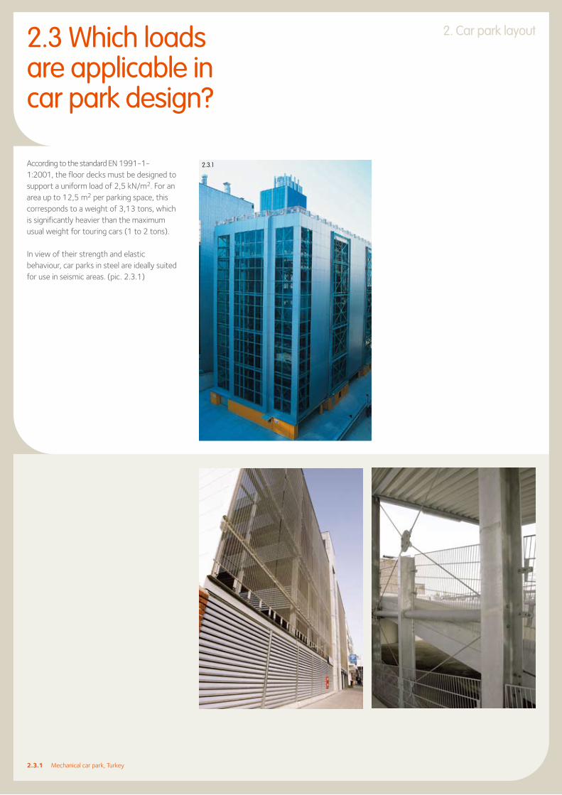
According to the standard EN 1991-1-1:2001, the floor decks must be designed to support a uniform load of 2,5 kN/m2. For an area up to 12,5 m2 per parking space, this corresponds to a weight of 3,13 tons, which is significantly heavier than the maximum usual weight for touring cars (1 to 2 tons).
In view of their strength and elastic behaviour, car parks in steel are ideally suited for use in seismic areas. (pic. 2.3.1)
2.3.1 Mechanical car park, Turkey
2.3 Which loads are applicable in car park design?
2.3.1

13
QVC Düsseldorf Car Park

15
3. SuItABLE CAR PARK StEEL StRuCtuRES3.1 Columns 163.2 Floor beams 17

3. Suitable car park steel structures3.1 Columns
The steel bearing structure consists of vertical columns and horizontal beams, usually connected by bolting (pic. 3.1.1). The horizontal forces due to wind and breaking of cars are transferred horizontally through the floor slabs to the vertical wind bracings or shear walls (e.g. stiff staircases).
In multi-storey car parks, the outer columns are spaced at intervals corresponding to the width of one or more parking spaces (units of 2,30 m to 2,50 m). Where the spacing between two columns exceeds 5 m, secondary beams are foreseen between the columns. Ideally, the distance between columns should correspond to the one of the main girders in order to avoid secondary beams, thus optimising the weight of the steel structure.
An optical delimitation of the parking spaces is obtained when the distance between columns coincides with the border width of each parking space.
In underground car parks, the position of the columns normally depends on the grid of the framework of the building above. In this case, it is important to limit the cross-section of the columns to the strict minimum by using hot-rolled sections or composite columns, which are ideal for this type of construction.
For the column sections, it is recommended to choose the steel grade S355 in order both to save weight and to reduce the size of the columns. In large-scale structures, it may be advantageous to choose the high-strength steel S460 featuring a 30% higher yield strength than grade S355.
For hot-rolled H-beams over 260 mm in height, steels with a yield strength up to 460 MPa are produced within ArcelorMittal using the particularly economic Quenching and Self-Tempering (QST) rolling process. These steels are commercialized under the brand name of HISTAR.
3.1.1 Simple beam-column connection using bolted angles3.2.1 Composite steel beam with studs welded in place before erection3.2.2 Design example of a composite floor beam with a construction height of 60 cm.
3.1.1

17
3. Suitable car park steel structures
Rolled steel sections in S355 steel with non composite,
prefabricated slabs
Rolled steel sections in S355 steel with
composite slab, poured on site (grade C25/30)
Span l = 16,00 m
Steel section spacing
b = 2,50 m
Excess load Q = 2,5 kN/m2
Slab thickness 100 mm 140 mm
G = 7,00 kN/mQ = 6,25 kN/m
G = 9,25 kN/mQ = 6,25 kN/m
Ed = 1,35*7,00 + 1,5*6,25
= 18,825 kN/m
M = Ed*16 /8 = 602,4 kNm
Ed = 1,35*9,25 + 1,5*6,25
= 21,86 kN/m
M = Ed*162/8 = 700 kNm
Section IPE 500 IPE 400
Mpl.y.Rd = 2194*355/(1,1*1000)
= 708 kNm > 602 kNm
The neutral axis lies within the slab:
zc = (Aa fy/ga)/(beff 0,85 fck/gc)
= 77 mm < 140 mm
Mpl.y.Rd = Fa*(ha/2+hp+hc-zc/2)
= 822 kNm > 700 kNm
Gauge 100 mm + 500 mm
= 600 mm 140 mm + 400 mm
= 540 mm
To limit the final deformation, the floor steel sections are given a camber corresponding to a load of G + max 1.3Q
3.2 Floor beams
The choice of the floor beams depends on their span, the type of concrete deck, and the available construction height. The various deck types consist either of cast-in-place concrete, composite or prefabricated concrete slabs.
l Cast-in-place concrete slabs can be made using temporary formwork or permanent formwork made of prefabricated concrete planks or metal deck.
l When using traditional, temporary formwork, the spacing between the steel beams may be freely selected according to the thickness of the concrete slab. However, for economic reasons, this spacing should not exceed 5 m and, in any case, it is a good idea to take advantage of the effect of connecting the rolled steel sections with the reinforced concrete floor.
Besides, it is always advisable to take advantage of the composite action between the concrete slab and the steel beam via metal studs welded on the upper flange of the H-section (pic. 3.2.1). Thanks to the composite effect, either savings of about 20% in the steel consumption can be achieved (table 3.2.2) or the construction height can be reduced.
hc+hp
ha
beff 0,85 fck/c
fy/a
hc
zc Fc
Fa
hp
ha/2
ha/2
3.2.1
3.2.2

Independently from the floor type, the steel beams are typically precambered in the workshop in order to compensate for the deformation resulting from the application of the dead load (weight of the concrete slab and the steel beam) and part of the life load (usually <30%) (pic. 3.2.5).
The amount of precamber is determined during static calculation and depends on the inertia of the statical system and the loads. In the unpropped condition, the deflection is calculated considering the statical properties of the steel section only. In the propped condition, the statical properties of the composite section are considered. Here, it is clear that the main girders are supported during the construction phase; thus the deflection from dead load is reduced.
S355 steels are usually chosen for the girders. However, savings in material and costs can be achieved by using light-weight IPE sections in high strength S460 steel.
In case of restricted construction heights, steel sections with smaller height but slightly heavier weight can be selected.
l Self-supporting metal decks from ArcelorMittal Construction in combination with cast-in place concrete avoid investing in the erection of formwork supporting frames, thereby shortening construction time.
Depending on the type, the metal decks act solely as formwork or in composite action.
Self-supporting metal decks are used for spans up to 3,33 m. In some markets, special metal decks allowing spans up to 5 m without support during the construction phase, are available. In order to limit cracks over the main girders, reinforcing bars have to be foreseen.
l Prefabricated concrete planks have thicknesses between 5 to 8 cm and can incorporate the lower reinforcement layer of the concrete deck. Cast-in-place concrete and the upper layer of reinforcement are added on top. Unsupported spans up to 5 m are possible with this system. In case of longer spans, temporary supports may be necessary during construction.
l Construction time can be further reduced by using pre-fabricated concrete slabs. These are made in the factory to very tight tolerances and assembled on site using the same lifting machinery as for the erection of the steel structure. Frictional linking of the prefabricated slabs can be provided by fixing with prestressed, high-strength bolts to the upper flange of the steel beams. This method requires very precise construction work.
In case of composite action between the prefabricated concrete slabs and the steel beam via metal studs, cope cuts have to be foreseen in the slab at the locations of the studs (pic. 3.2.3).
Particular attention has to be paid to the filling of the joints with special mortar. In the case of temporary car parks, non-composite design is usually chosen in combination with beams in high-strength S460 steel. In order to avoid lateral torsional buckling and to transfer horizontal loads, the prefabricated slabs are fixed to the upper flange of the beams. The joints between the slabs are sealed with a permanently elastic material (fig. 3.2.4).
3.2.3 Composite action by sealing the joints with special mortar3.2.4 Hilgers system3.2.5 Composite steel sections with camber before placement of the metal decks
3.2.4
3.2.3 3.2.5

19
3.2.6 Studs welded through the metal deck on site3.2.7 Comparison between different steel grades for a non composite floor system3.2.8 Comparison between different steel grades for a composite floor system
Span 16,00 m
Steel section spacing 5,00 m
Prefabricatedslab thickness
120 mm
Life load 2,50 kN/m2
Grade of steel S235 S355 S460
Section IPE 750x196 IPE 750x147 IPE 600
Height of section (mm) 770 753 600
Height ratio 1,02 1,00 0,8
Linear weight of section (kg/m)
196 147 122
Linear weight ratio 1,33 1,00 0,83
Span 16,00 m
Steel section spacing 5,00 m
Prefabricatedslab thickness
140 mm
Life load 2,50 kN/m2
Grade of steel S235 S355 S460
Section IPE 600 IPE 550 IPE 500
Height of section (mm) 600 550 500
Height ratio 1,09 1,00 0,91
Linear weight of section (kg/m)
122 106 91
Linear weight ratio 1,15 1,00 0,86
Beams in S460 steel can also be used in composite floors. Tables 3.2.7 and 3.2.8 show the influence of steel grades and composite or non composite design for a span of 16 m. on the construction height and the weight.
3.2.7
3.2.8
3.2.6
3.Suitable car park steel structures

21
4. CoRRoSIoN AND FIRE PRotECtIoN oF StEEL StRuCtuRES 4.1 Corrosion protection 224.2 Fire protection/application of the Natural Fire Concept 22

4.1 Corrosion protection
Nowadays, corrosion protection of steel car park structures is usually achieved by hot-dip galvanization. During this process, rust and mill scale are removed from the surface of the beam in a pickling bath before immersion during 5-10 minutes in the bath of liquid zinc at 450 °C. Typically, a 150-250 μm thick zinc layer is formed which will protect the steel surface against atmospheric corrosion.
In case of severe climatic conditions, an additional paint can be applied on top of the zinc layer. This so-called DUPLEX system minimises maintenance costs and substantially increases the duration of protection against corrosion.
The development of new paints has also led to a considerable improvement in corrosion protection.
Experience shows that usual paints provide protection lasting from 10 to 20 years, depending on the atmospheric conditions. At the end of this period, it is usually sufficient to renew the finishing coat, whereby the use of a new colour can be considered to change the outside appearance of the building.
Corrosion protection by paints consists of cleaning the surface of the steel section and applying several layers of compatible coats. A typical surface treatment reads as follows:
l shot blasting of the surface, degree of purity SA 2.5
l primer – 15 to 25 μm
4.2 Fire protection Application of the Natural Fire Concept
l one or two intermediary coat layers, (thickness – 2 x 40 or 1 x 80 μm)
l two finishing coat layers (thickness – 2 x 60 μm)
Apart from the final coat layer, painting is performed in the workshop. After erection, damaged areas are repaired and the final coat layer is applied on site.
For more details on the galvanisation process, the brochure, “Corrosion protection of rolled steel sections using hot dip galvanisation” is available on the website
sections.arcelormittal.com
According to the regulations of most European countries, there are no fire-resistance requirements for steel structures of open multi-storey car parks.
A car park is considered open if each storey has openings equal to one third of the total surface area of the outer walls of this level (fig. 4.2.1) and if effective and permanent ventilation is guaranteed.
For the countries where there are fire resistance requirements, fire engineering is considered as an alternative to the conventional ISO fire approach which requires passive protection of the steel elements. The data on which the Natural Fire Concept is based (fire load, rate of heat development, number of vehicles involved) have been determined in numerous tests carried out in several countries. Also, statistics from the last decades show that the propagation of fire from a single vehicle has rarely involved more than 3 adjacent vehicles.
During real tests (pic. 4.2.2), localised maximum steel temperatures slightly above 700 °C were recorded for a short period of time in the unprotected columns and beams. These temperatures did not lead to the collapse or even deformation of the structure (pic. 4.2.3). As a conclusion, fire engineering allows to build unprotected steel structures in open car parks.
Unlike open car parks, closed or underground car parks are subject to more stringent fire resistance requirements.
4.2.2

23
4. Corrosion and fire protection of steel structures
4.2.1
Here, in order to guarantee the one or two hours ISO fire-resistance, the columns and beams are generally constructed using the composite anti-fire (AF) system in which the chambers between the flanges of the H-sections are filled with reinforced concrete (pic. 4.2.4). These composite columns and beams transmit the loads by the combined action of steel and concrete.
In addition to its load carrying capability, the concrete plays here a role in fire resistance as it protects the encased steel from a rapid rise in temperature. Moreover, this system features good behaviour in case of vehicle impact, thanks to the external location of the steel flanges.
A detailed description and software for designing the composite AF columns and beams can be obtained from thel Commercial Sections division of ArcelorMittal and its sales offices.
Under certain conditions (mechanical ventilation and active fire-fighting measures), the application of the Natural Fire Concept enables passive protection to be omitted for the steel beams of closed or underground car parks.
4.2.1 Detail of an open multi-storey car park4.2.2 Real fire test carried out on an unprotected steel car park structure, Vernon (France)4.2.3 Steel structure after the fire test, Vernon (France)4.2.4 Detail of floor beams without passive protection in an underground car park
4.2.3
4.2.4
IPE 400 AA
14
00
HE 120 A
HE 160 B
14
00
80
06
00
27
80
IPE 500 AA
Roof steel section
Floor steel section


25
5. DuRABILIty oF StEEL StRuCtuRES
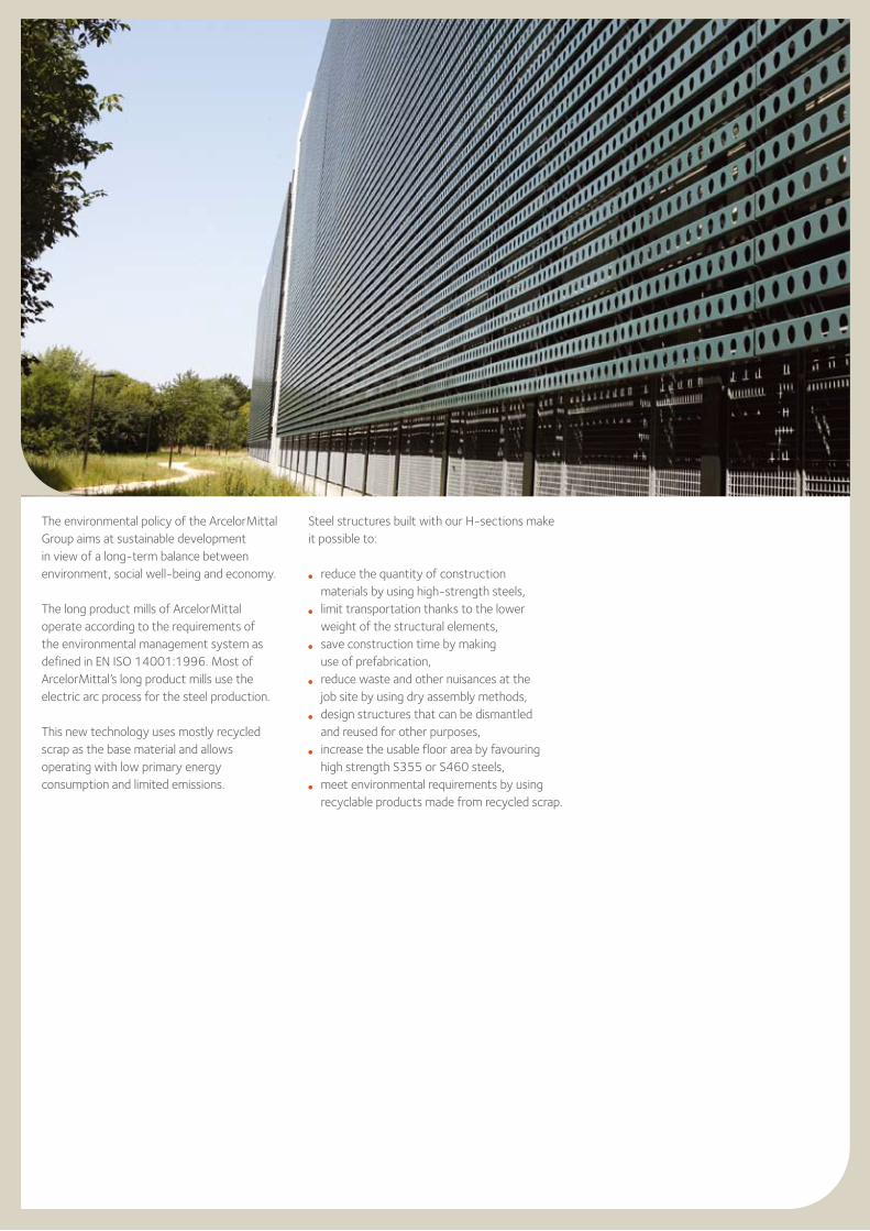
The environmental policy of the ArcelorMittal Group aims at sustainable development in view of a long-term balance between environment, social well-being and economy.
The long product mills of ArcelorMittal operate according to the requirements of the environmental management system as defined in EN ISO 14001:1996. Most of ArcelorMittal’s long product mills use the electric arc process for the steel production.
This new technology uses mostly recycled scrap as the base material and allows operating with low primary energy consumption and limited emissions.
Steel structures built with our H-sections make it possible to:
l reduce the quantity of construction materials by using high-strength steels,
l limit transportation thanks to the lower weight of the structural elements,
l save construction time by making use of prefabrication,
l reduce waste and other nuisances at the job site by using dry assembly methods,
l design structures that can be dismantled and reused for other purposes,
l increase the usable floor area by favouring high strength S355 or S460 steels,l meet environmental requirements by using
recyclable products made from recycled scrap.

27
Car park Bouillon, Luxembourg
5. Durability of steel structures
Finishing
As a complement to the technical capacities of our partners, we are equipped with high-performance finishing tools and offer a wide range of services, such as:
l drillingl flame cuttingl T cut-outsl notchingl camberingl curvingl straighteningl cold sawing to exact lengthl welding and fitting of studsl shot and sand blastingl surface treatment
Building & Construction Support
At ArcelorMittal we also have a team of multi-product professionals specialising in the construction market.
A complete range of products and solutions dedicated to construction in all its forms: structures, façades, roofing, etc. is available from the website
www.constructalia.com
Pictures of QVC Düsseldorf, Düren and Rheda-Wiedenbrück car parks, courtesy of Vollack Management GmbH & Co. KG (Karlsruhe, Germany).
technical assistance& Finishing
Technical assistance
We are happy to provide you with free technical advice to optimise the use of our products and solutions in your projects and to answer your questions about the use of sections and merchant bars. This technical advice covers the design of structural elements, construction details, surface protection, fire safety, metallurgy and welding.
Our specialists are ready to support your initiatives anywhere in the world.
To facilitate the design of your projects, we also offer software and technical documentation that you can consult or download from our website:
sections.arcelormittal.com

ArcelorMittal Commercial Sections66, rue de LuxembourgL-4221 Esch-sur-AlzetteLuxembourgTel.: +352 5313 3014Fax: +352 5313 3087
sections.arcelormittal.com
We operate in more than 60 countries on all five continents. Please have a look at our website under “About us” to find our local agency in your country.
Although every care has been taken during the production of this brochure, we regret
that we cannot accept any liability in respect of any incorrect information it may contain
or any damages which may arise through the misinterpretation of its contents.
your partners

ArcelorMittal Commercial Sections
66, rue de LuxembourgL-4221 Esch-sur-AlzetteLUXEMBOURGTel.: + 352 5313 3010Fax: + 352 5313 2799
sections.arcelormittal.com
Vers
ion
20
14
-1