Car Park & Industrial Barriers
28
www.ingalcivil.com.au Release 05/16 Product Manual Car Park & Industrial Barriers
Transcript of Car Park & Industrial Barriers

www.ingalcivil.com.au
Release 05/16
Product Manual
Car Park &Industrial Barriers

2Release 05/16
Car Park & Industrial Barriers
1.0 IntroductionOff highway vehicle safety barriers are a specific range of barriers designed for use in car parks, logistics yards, warehouses, factory facilities, retail parks, loading bays, and many other non-roadside applications. Their objective is the protection of people, plant and buildings.
Traditional highway safety barrier systems are designed to contain and redirect errant vehicles traveling at high velocities and relatively low impact angles. Posts are driven into the ground and the surrounding soil provides lateral post support.
Ingal Civil Products’ range of car park and industrial barriers are specifically designed for applications where protection is required from heavy vehicle glancing blows and low speed perpendicular impacts. Traditional bolt down rigid posts provide no energy absorption upon impact resulting in damage to the barrier and post foundations. Ingal’s range of flexible post systems absorb impact energy, thereby reducing the pullout forces on the holding down bolts. Fewer holding down bolts are required resulting in an easier to install system and minimal damage to valuable plant and equipment.
2.0 Barrier SelectionAny general perimeter barrier system must be capable of withstanding the relevant impact loads and minimise any residual energy being passed onto the structure that is being protected. The selection of an effective perimeter edge protection is based on a number of variable factors;
• Spaceavailableinwhichtoinstallabarriersystemandminimise any encroachment into the travelled way.
• Climbabilityofthebarrier.
• Handrail attachments and mesh infill systemrequirements.
• Edgedetail in relation to suitable anchorageof thebarrier system.
• Compliance with relevant Australian Standards andBuilding Codes

3Release 05/16
Car Park & Industrial Barriers
3.0 Standards
3.1 AS/NZS 1170.1:2002 Structural Design Actions, Part 1: Permanent, imposed and other actions
The horizontal impact force on a barrier arising from the movement of vehicles may be calculated as follows;
F = mv2/2D
Where:
F = impact force (N)
m = gross vehicle mass (kg)
v = velocity of the vehicle (m/s)
D= sum of the deflection of the vehicle (crumple zone) and barrier (m).
The impact force shall be distributed over a 1.5m length at any position along the barrier and shall be assumed to act at 0.5m above floor level for light traffic areas.
Light traffic areas are defined as parking, garages, and driveways restricted to cars, light vans, etc, not exceeding 2500kg gross mass.
In practical terms for car parks, the horizontal impact force on a barrier in a light traffic area is based on a 1500kg vehicle travelling at 2m/s and a 0.1m crumple zone.
The top edge or handrail shall also be designed for the case where a concentrated load of 0.6kN, positioned for the worst effect, acts inward, outward or downward.

4Release 05/16
Car Park & Industrial Barriers
3.2 AS2890.1:2004 Parking Facilities, Part 1: Off street car parking
Barriers shall be constructed to prevent vehicles from running over the edge of a raised platform or deck of a multi-storey car park including the perimeter of all decks above ground level.
They are required wherever the edge from the deck to a lower level exceeds 600mm
3.3 AS/NZS 1657:1992 Fixed Platforms, Walkways, Stairways and
Ladders - Design, Construction and Installation
In walkway areas, a top rail, supported by posts, parallel to the floor or slope of a walkway at a vertical height of not less than 900mm or more than 1100mm is required.
The space between the top rail and the floor may be provided with suitable infill fixed to the top rail and not more than 80mm above the floor. Infill may be fabricated from solid or perforated plate, expanded metal or metal mesh.
3.4 Building Code of Australia
The building code specifies that for balustrading on balconies greater than 1m from the ground, any members (vertical or horizontal) should not permit a 125mm sphere to pass between them.
Once a balcony height of 4m has been exceeded, balustrades should be 1m in height and any horizontal elements within the balustrade or other barrier between 150mm

5Release 05/16
Car Park & Industrial Barriers
4.0 Zee ParkThe ZEE Park is a high-strength steel car park barriersystem.
4.1 Features & Benefits• Fullytested&compliantsystemforpeaceofmind
• LowInitialDeflection-20mmat30kN
• Suitable for edge protection close to structures orbuilding facades
• Yielding design prevents damage to footings withlarger impacts
• Consistenthighperformance
• Highcontainmentcapacity
• Single Anchor design – Easier, cost-effectiveinstallation
• Handrail&Anti-ClimbMeshattachmentsavailableforBCA compliance
• Verylowfootprint(Only100mmx200mm)
• 100% Australian made using Australian Steel &Australian Zinc
4.2 Installation instructions – Site Preparation
The site should be prepared free of hazards that may interfere with the installation or operational performance of the system. Some sites may requireminor leveling,which can be achieved by placing steel packing plates under the posts.
Recommended Plant & Tools
• TapeMeasure
• StringLine
• HammerDrill
• CordlessDrill
• TorqueWrench
• AirCompressor
• AirRattleGun
• SmallTools
4.3 Installation Sequence
The following written instructions should be read in conjunction with Ingal Civil Products Drawings:
• STB-020 ZEEParkPostArrangement
• STB-021 HandrailExtensionandMeshInfill Panel Arrangement
4.4 Post Installation1. Using a string line, commence set out by marking the
ground for each post location. Posts will typically be at 2000mm centres (max).
2. Leave at least 25mm between the base of the post and any structure to allow for dynamic deflection
3. Drill22mmholesforeachposttoadepthof170mm.Ensuretheholesarecleanfreefromdustanddebris.
4. Place the post above the drilled hole.
5. Follow mixing instructions for anchoring epoxy carefully.EpoxyM20x180mmstudwithnutthroughZEEParkpostanchorslot
6. Allow epoxy adhesive to fully cure before torqueing M20nutto150Nm.
4.5 Handrail Extension Attachment1. Align the handrail extension piece with the post and
secure through the upper hole in the extension piece usinganM16x32mmbolt.
4.6 Rail Attachment1. Align the w-beam sections with the posts and secure
usingtheM16x32mmbolts.
2. If a handrail extension piece is attached, ensure the extension is vertical before securing the bolts.
3. SplicerailstogetherusingM16x32mmbolts.Eight(8)bolts are required per splice.
4. Rails should be lapped so that the exposed edge is facing away from approaching traffic.

6Release 05/16
Car Park & Industrial Barriers
4.7 Handrail Attachment1. Align the handrail section with the extension pieces
and secure the handrail with Tek-screws.
2. Joins in the handrail are made by butting adjacent handrails together at the post extensions prior to securing with Tek- screws.
3. If a handrail join cannot be located at the postextension, adjacent rails can be spot welded together. A zinc rich paint should then be applied to the welded surfaces.Alternatively,HandrailJoiners(partnumber10005563)maybeused,securedwithweldsorTek-screws.
4.8 Anti-Climb Mesh Attachment1. Align the anti-climb panel sections with the front face
of the w-beam sections.
2. Using Tek-screws and saddle washers, secure the mesh panels to the w-beam sections ensuring a gap of not less than 100mm exists between ground level and the bottom of the mesh panel.
3. Tek-screwsareattachedthroughthetopandbottomcorrugations of the w-beam sections at spacings of 500mm along the length of the beams.
4. The mesh panels are secured to each handrail extension pieces with a Tek-screw.
5. Joins in the mesh panels are made by butting adjacent panels together and securing with saddle clips ensuring both panels are secured. An additional saddle clip should be attached at the bottom of the panels.
6. Align the stiffening section with the top of the mesh panels and secure to the handrail extensions using anM12x50mmbolt through thepre-punchedholeapproximately 100mm below the handrail.
7. Joins in thestiffeningsectionsaremadebybuttingadjacent sections together.
8. Between handrail extension pieces, drill holes at 500mm centres and attach the stiffening section to themeshusingM12x50mmbolts.

7Release 05/16
Car Park & Industrial Barriers
Zee-Park Installation Checklist
Customer:
Project:
Checked By:
Signed:
Date
Post Installation
Is the area clear of obstacles that may impede the operational performance of the system Yes No
Havethepostsbeenpositionedatamaximum2000mmspacing Yes No
Are the posts orientated correctly Yes No
HavethepostsbeeninstalledusingmechanicalorchemicalanchorsnominatedinICPdrawings Yes No
Handrail Installation
Arethehandrailextensionssecuredtothepostswithtwo(2)M16bolts Yes No
Are the handrail extensions vertical Yes No
Hasthehandrailbeenattachedtotheextensionpieceswithtekscrews Yes No
Rail Installation
Are the rails secured to each post Yes No
Aretherailssplicedwitheight(8)M16x32mmbolts Yes No
Are the rails spliced ensuring the exposed edge is facing away from oncoming traffic Yes No
Mesh Infill Installation
Is the gap between the bottom of the mesh panel and ground level less than 100mm Yes No
Hasthemeshbeenattachedtotheupperandlowerconfigurationsoftherailsusingtekscrewsand saddle clips of 500mm centres Yes No
Hastheanti-climbmeshsectionsbeenjoinedensuringthesaddleclipsengageadjoiningpanels Yes No
Hasthestiffeningsectionbeenattachedtothehandrailextensionsandthetopofthemeshpanels Yes No
General
Where the galvanizing has been damaged, has the coating been repaired with a zinc-rich paint Yes No
Are all fasteners secure Yes No
Is all rubbish and debris removed Yes No
Installation ChecklistPleasecompletethefollowinginstallationchecklisttoensureZEEParksystemperformsasdesigned.
8Release 05/16
Car Park & Industrial Barriers
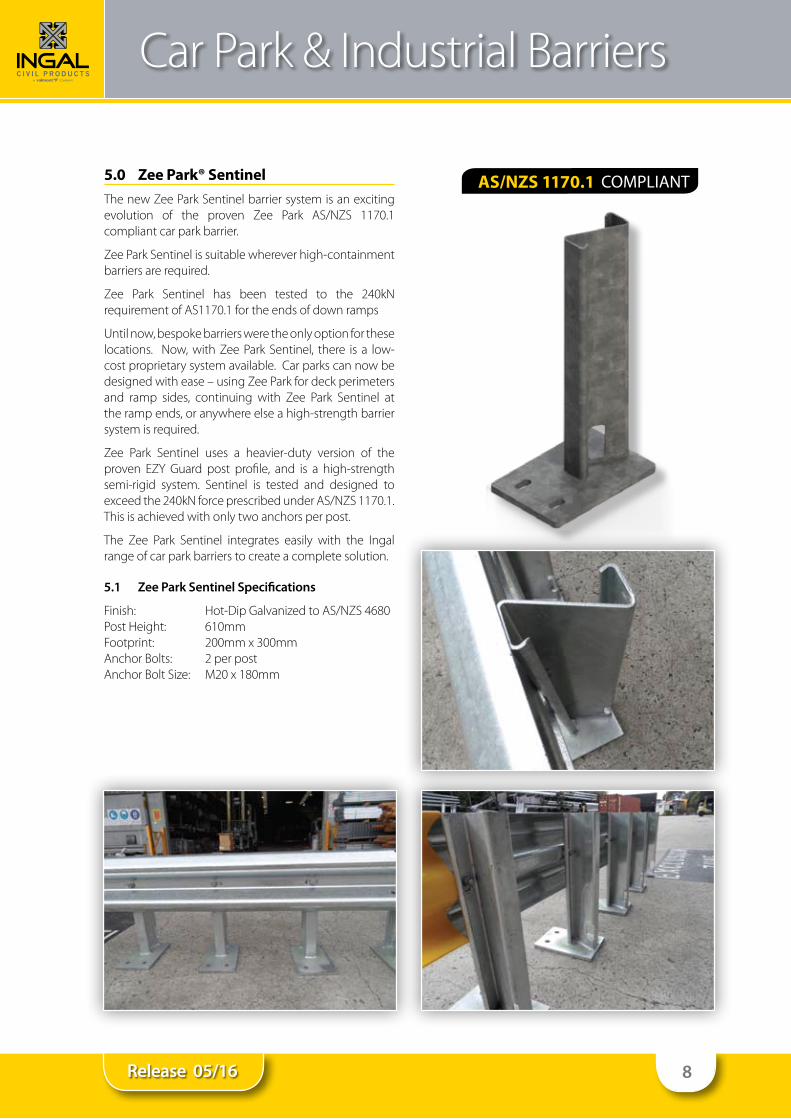
5.0 Zee Park® SentinelThenewZeeParkSentinelbarriersystemisanexcitingevolution of the proven Zee Park AS/NZS 1170.1compliant car park barrier.
ZeeParkSentinelissuitablewhereverhigh-containmentbarriers are required.
Zee Park Sentinel has been tested to the 240kNrequirementofAS1170.1fortheendsofdownramps
Until now, bespoke barriers were the only option for these locations. Now,withZeeParkSentinel, there is a low-cost proprietary system available. Car parks can now be designedwithease–usingZeeParkfordeckperimetersand ramp sides, continuing with Zee Park Sentinel atthe ramp ends, or anywhere else a high-strength barrier system is required.
Zee Park Sentinel uses a heavier-duty version of theproven EZY Guard post profile, and is a high-strengthsemi-rigid system. Sentinel is tested and designed toexceedthe240kNforceprescribedunderAS/NZS1170.1.This is achieved with only two anchors per post.
The Zee Park Sentinel integrates easily with the Ingalrange of car park barriers to create a complete solution.
5.1 Zee Park Sentinel Specifications
Finish: Hot-DipGalvanizedtoAS/NZS4680PostHeight: 610mmFootprint: 200mmx300mmAnchor Bolts: 2 per postAnchorBoltSize: M20x180mm
AS/NZS 1170.1

9Release 05/16
Car Park & Industrial Barriers
6.0 Zee Park® DeckGuardThe New Zee Park® DeckGuard barrier system is anexcitingevolutionoftheprovenZeeParkAS/NZS1170.1compliant car park barrier
ZeePark®DeckGuardisdesignedtoallowmaximumuseof car park floor space, by placing the Flex-Beam guard rail right at the edge of the car park deck. This gives maximum protection with a minimum of space.
TheZeePark®DeckGuardalsousestheprovenEZYGuardpost profile, and is a high-strength semi-rigid system. DeckGuard is testedanddesignedtoexceedthe forceprescribed under AS/NZS 1170.1 for light traffic areas.This is achieved with a single anchor per post.
The Zee Park® is designed to spring under light ‘nudge’ impacts, but predictably yield under severe impacts, preventing damage to the car park structure.
ZEEPark is suitable foredgeprotection inmulti-storeycar parks, and is without doubt the most versatile car park barrier system available.
6.1 Zee Park DeckGuard Specifications
Finish: Hot-DipGalvanizedtoAS/NZS4680PostHeight: 610mmFootprint: 100mmx175mmAnchor Bolts: 1 per postAnchorBoltSize: M20x180mm
AS/NZS 1170.1

10Release 05/16
Car Park & Industrial Barriers
7.0 Zee Park® TruckShieldZeeParkTruckShieldhasbeentestedtotherequirementsofAS1170.1formediumtrafficareas,andissuitableforfreight terminals, logistics facilities, loading docks, or anywhere separation of heavy vehicles and pedestrians is required.
ZeeParkTruckShieldusesaheavier-dutyversionoftheproven EZY Guard post profile, and is a high-strengthsemi-rigid system. TruckShield is tested and designedto exceed the force prescribed under AS/NZS 1170.1for medium traffic areas. This is achieved with only two anchors per post.
Easy installation of the Australian made Zee ParkTruckShieldmakesitanidealchoiceforaheavydutycarpark barrier system.
TheZeeParkTruckShieldIntegrateseasilywiththeIngalrange of car park barriers to create a complete solution.
Suitable for:
• Freightterminals• Logisticsfacilities• Loadingdocks• Anywhere separation of heavy vehicles and
pedestrians is required
7.1 Zee Park TruckShield Specifications
Finish: Hot-DipGalvanizedtoAS/NZS4680PostHeight: 1055mmFootprint: 200mmx300mmAnchor Bolts: 2 per postAnchorBoltSize: M20x180mm
AS/NZS 1170.1

11Release 05/16
Car Park & Industrial Barriers
Zee Park Sentinel, DeckGuard and TruckShield Installation Checklist
Customer:
Project:
Checked By:
Signed:
Date
Post Installation
Is the area clear of obstacles that may impede the operational performance of the system Yes No
Havethepostsbeenpositionedatamaximum2000mmspacing Yes No
Are the posts orientated correctly Yes No
HavethepostsbeeninstalledusingtherequirednumberofM20x180mmanchors, with the specified chemical adhesive? Yes No
Handrail Installation
Arethehandrailextensionssecuredtothepostswithtwo(2)M16bolts Yes No
Are the handrail extensions vertical Yes No
Hasthehandrailbeenattachedtotheextensionpieceswithtekscrews Yes No
Rail Installation
Are the rails secured to each post Yes No
Aretherailssplicedwitheight(8)M16x32mmbolts Yes No
Are the rails spliced ensuring the exposed edge is facing away from oncoming traffic Yes No
Mesh Infill Installation
Are the angle sections attached at the top and bottom of the handrail extension pieces Yes No
Are the mesh anti-climb sections attached to the lower or upper corrugation of the rail using tek screws and saddle washers at 500mm centres Yes No
Are the anti-climb mesh sections tethered at the joins using saddle washers Yes No
General
Where the galvanizing has been damaged, has the coating been repaired with a zinc-rich paint Yes No
Are all fasteners secure Yes No
Is all rubbish and debris removed Yes No
Installation ChecklistPleasecompletethefollowinginstallationchecklisttoensureZEEParkSentinel,DeckGuardandTruckShieldsystemsperforms as designed.
12Release 05/16
Car Park & Industrial Barriers
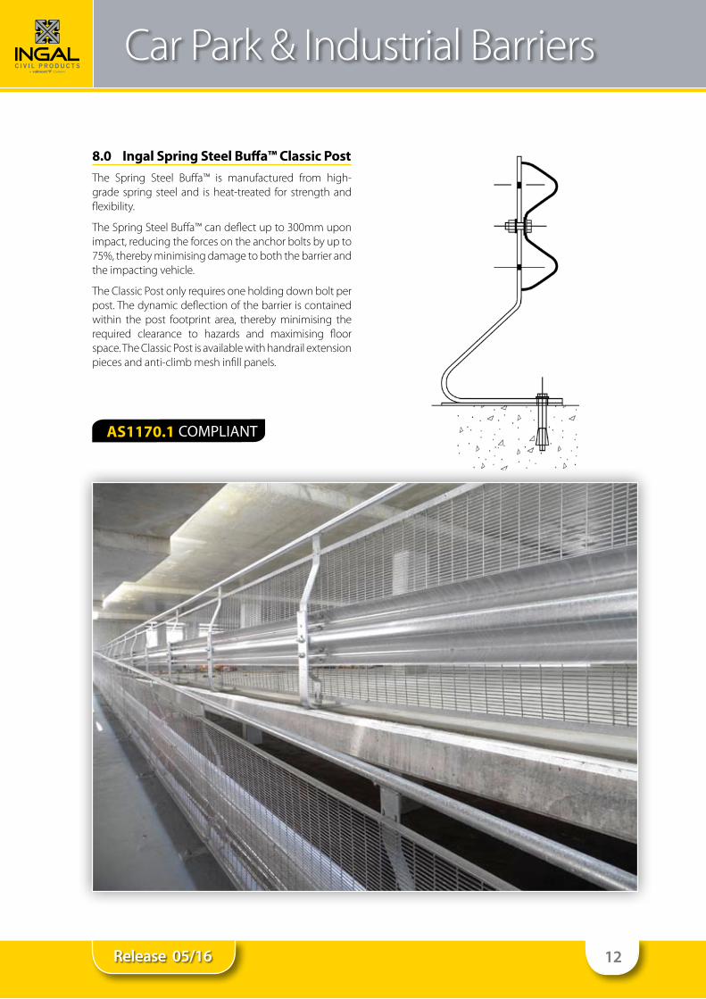
8.0 Ingal Spring Steel Buffa™ Classic Post The Spring Steel Buffa™ is manufactured from high-grade spring steel and is heat-treated for strength and flexibility.
TheSpringSteelBuffa™candeflectupto300mmuponimpact, reducing the forces on the anchor bolts by up to 75%,therebyminimisingdamagetoboththebarrierandthe impacting vehicle.
The Classic Post only requires one holding down bolt per post. The dynamic deflection of the barrier is contained within the post footprint area, thereby minimising the required clearance to hazards and maximising floor space. The Classic Post is available with handrail extension pieces and anti-climb mesh infill panels.
AS1170.1

13Release 05/16
Car Park & Industrial Barriers
8.1 Classic Post Specifications
Finish: HotDipGalvanizedtoAS4680PostHeight: 610mmFootprint: 300x100mmMax.PostSpacing: 2000mmDeflection: Upto300mmWeight: 11kgAnchor Bolts: 1 off per postAnchorBoltSize: Dependentuponapplication
8.2 Classic Post Applications• Perimeter edge and split-level protection formulti-
storey car parks
• Internal and external barrier protection for walls inwarehouses and logistic depots
• Protectiontohighvalueplantandequipment
• Loadingbayramps

14Release 05/16
Car Park & Industrial Barriers
9.0 Ingal Spring Steel Buffa™ Standard Post
TheSpringSteelBuffa™ismanufacturedfromhigh-gradespring steel and is heat-treated for strength and flexibility. TheSpringSteelBuffa™candeflectupto300mmuponimpact, reducing the forces on the anchor bolts by up to 75%,therebyminimisingdamagetoboththebarrierandthe impacting vehicle.
TheStandardPostonlyrequiresoneholdingdownboltper post. Rail can be mounted either side of the standard post in order to maximise floor space or to prevent post feet being a trip hazard or to minimize damage to tyres. The Standard Post is availablewith handrail extensionpieces and mesh infill panels
9.1 Standard Post Specifications
Finish: HotDipGalvanizedtoAS4680PostHeight: 610mmFootprint: 300x100mmMax.PostSpacing: 2000mmDeflection: Upto300mmWeight: 11kgAnchor Bolts: 1 off per postAnchorBoltSize: Dependantuponapplication
9.2 Standard Post Applications• Rampprotectiononmulti-storeycarparks
• Splitlevelprotectiononmulti-storeycarparks
• Internal and external barrier protection for walls inwarehouses and logistic depots
• Protectiontohighvalueplantandequipment
• Loadingbayramps
AS1170.1

15Release 05/16
Car Park & Industrial Barriers
10.0 Rigid Post SystemsFor very light impacts, the inherent strength of a steel barrier, rigidly mounted may be sufficient to withstand impacts without suffering damage. However, the fullload of any impact is passed through the barrier into theholdingdownbolts.Strongerimpactswillthereforeresult in damage to the impacting vehicle, the barrier and the foundations.
Rigid posts are available as C posts or U posts depending upon site requirements.
10.1 Rigid Post Specifications
Finish: HotDipGalvanizedtoAS4680PostHeight: 700or750mm(CPost) 700mm(UPost)Footprint: 200 x 280mm (C Post) 300x300mm(UPost)TypicalPostSpacing: 2000mmDeflection: UntestedtoAS/NZS1170.1:2002Weight: 18kgAnchor Bolts: 4 off per postAnchorBoltSize: Dependantuponapplication
10.2 Rigid Post Applications• Glancing blow collisions at low speeds with light
vehicles
• Internal and external barrier protection for walls inwarehouses and logistic depots

16Release 05/16
Car Park & Industrial Barriers
11.0 Ingal Column Buffa™Supporting columns are highly vulnerable to damagefrom vehicle traffic. Repairs are usually costly, and damage may affect the structural integrity of the supporting column.TheColumnBuffa™isalsosuitableforexposedpipework and lighting columns that are located in trafficable areas.
TheColumnBuffa™isavailableinfullorsemi-circleunitswith single or double rail, providing protection from low speedimpacts.ColumnBuffas™aresupportedbyspringsteel posts ensuring that damage to the barrier, structure and impacting vehicle is minimised. Posts can be turned inwardstopreventatriphazardordamagetotyres.Eachsupporting post only requires one holding down bolt per post.
11.1 Column Buffa Specifications
Finish: HotDipGalvanizedtoAS4680PostHeight: 610mmInternalDiameters: 750and1000mmAnchor Bolts: 1 per postAnchorBoltSize: Dependentuponapplication

17Release 05/16
Car Park & Industrial Barriers
12.0 Installation of Classic and Standard Post Systems
12.1 Site Preparation
The site should be prepared free of hazards that may interfere with the installation or operational performance of the system.
Some sitesmay requireminor leveling, which can beachieved by placing steel packing plates under the posts.
12.2 Recommended Plant & Tools• TapeMeasure
• StringLine
• LevellingDevice
• DrillingTools
• TorqueWrench
• CuttingTools
• HandTools
12.3 Installation SequenceThe following written instructions should be read in conjunction with Ingal Civil Products Drawings;
STB-004ClassicPostArrangement
STB-018StandardPostArrangement
STB-06Flexi-PostArrangementSTB-35 Handrail Extension and Mesh Infill PanelArrangement
12.3.1 Post Installation1. Using a string line, commence set out by marking the
ground for each post location. Posts will typically be at 2m centres (max).
2.If installing the standard post, provide a 300mmclearance from the post to the hazard to accommodate for the expected dynamic deflection.
3.Ifinstallingaclassicpost,thedynamicdeflectionofthesystem will be contained within the post footprint.
4. Drill holes for each post to the depths as required by the nominated anchor bolt size. If securing with chemical anchors, ensure the holes are free from dust and debris.
5. Place the post above the drilled hole(s) and insert the holding down bolt, tighten to snug tight.

18Release 05/16
Car Park & Industrial Barriers
12.3.2 Handrail Extension Attachment1. Align the handrail extension piece (also called a
crank) with the post and secure through the pre-punched upper hole in the extension piece using an M16x50mmbolt.
Note: Custom height barriers may require an additional;M16x50Bolt throughthe lowerholeofthe extension piece and post.
12.3.3 Rail Attachment1. Align the w-beam sections with the posts and secure
using the bolts nominated in the ICP drawings.
2. If a handrail extension piece is attached, ensure the extensionisverticalbeforesecuringtheM16x65mmbolt through the rail, post and handrail.
3.Splice rails together usingM16x32mbolts eight (8)bolts are required per splice.
4. Rails should be lapped so that the exposed edge is facing away from the approaching traffic.
12.3.4 Handrail Attachment1. Align the handrail section with the extension pieces
and secure the handrail with tek screws.
2. Joins in the handrail are made by butting adjacent handrails together at the post extensions prior to securing with tek screws.
3.If a handrail join cannot be located at the postextension, adjacent rails can be spot welded together. A zinc rich paint should then be applied to the welded surfaces.
Note: Joiners are available from Ingal Civil Products for handrail sections and are recommended to avoid welding.
Howevertheaboveinstructionsaretobefollowedifyouare not using a handrail joiner.
12.3.5 Anti-Climb Mesh Attachment1. Align the angle sections with the pre-punched holes
in the handrail extension piece located approximately 100mmbelowthehandrailandsecureusinganM8x30mmcupheadboltandnut.Duplicatethisprocessat the bottom prepunched hole of the handrail extension piece approximately 100mm from the ground.
2. Joins in the angle sections are made by butting adjacent sections together at the extension piece.
3. Placetheanti-climbmeshpanelsectionsbetweentheangle sections, secure at the top and bottom angle sections using the tek screws and saddle washers and also through the
corrugation of the w-beam section.
4. Continue this process at spacings of 500mm along the length of the run to secure the mesh.
5. Joins in the mesh panels are made by butting adjacent panels together and securing with the saddle washers and tek screws at the extension piece ensuring both panels are secured.

19Release 05/16
Car Park & Industrial Barriers
Classic and Standard Post System Installation Checklist
Customer:
Project:
Checked By:
Signed:
Date
Post Installation
Is the area clear of obstacles that may impede the operational performance of the system Yes No
Havethepostsbeenpositionedatamaximum2000mmspacing Yes No
Are the posts orientated correctly Yes No
HavethepostsbeeninstalledusingM20x180mmthreadedrodandchemicaladhesive Yes No
Handrail Installation
Arethehandrailextensionssecuredtothepostswithtwo(2)M16bolts Yes No
Are the handrail extensions vertical Yes No
Hasthehandrailbeenattachedtotheextensionpieceswithtekscrews Yes No
Rail Installation
Are the rails secured to each post Yes No
Aretherailssplicedwitheight(8)M16x32mmbolts Yes No
Are the rails spliced ensuring the exposed edge is facing away from oncoming traffic Yes No
Mesh Infill Installation
Are the angle sections attached at the top and bottom of the handrail extension pieces Yes No
Are the mesh anti-climb sections attached to the lower or upper corrugation of the rail using tek screws and saddle washers at 500mm centres Yes No
Are the anti-climb mesh sections tethered at the joins using saddle washers Yes No
General
Where the galvanizing has been damaged, has the coating been repaired with a zinc-rich paint Yes No
Are all fasteners secure Yes No
Is all rubbish and debris removed Yes No
Installation ChecklistPleasecompletethefollowinginstallationchecklisttoensureClassicandStandardPostsystemsperformasdesigned.

20Release 05/16
Car Park & Industrial Barriers
13.0 AccessoriesThe following accessories are available to compliment your range of car park and industrial barriers;
• PostCaps
• ShortW-beamBullnoseEnds
• WheelStops
• SpeedHumps
• CornerProtectas
• PlasticRailCaps
• SteelBollards

21Release 05/16
Ingal Civil ProductsIngal Civil Products

22Release 05/16Page 17
RELEASE 004

23Release 05/16Page 19
RELEASE 004
ST
AN
DA
RD
PO
ST
CLA
SS
IC P
OS
T

24Release 05/16

25Release 05/16
APPROVED
DRAWN
SCALE
Rev:
NAMEDATE
CHECKED
@
ISSUE FORINFORMATION ONLY
CIV
IL P
RO
DU
CT
SCO
MPANY
valm
ont
A
ZEE PARK DECK GUARDW
ITH MESH AND HANDRAIL 1100mm HIGHGENERAL ARRANGEMENT
STB-0480
N.T.S.A3
J:\SALES & MARKETING\ENGINEERING ARCHIVE\STANDARDS\STB_STD\DWGS\STB-048 DECK GUARD ZEE PARK WITH HANDRAIL AND MESH.DWG
0ORIGINAL ISSUE

26Release 05/16
APPROVED
DRAWN
SCALE
Rev:
NAMEDATE
CHECKED
@
ISSUE FORINFORMATION ONLY
CIV
IL P
RO
DU
CT
SCOM
PANYvalm
ont
A
0
N.T.S.A3
J:\SALES & MARKETING\ENGINEERING ARCHIVE\STANDARDS\STB_STD\DWGS\STB-046 ZEE PARK TRUCK SHIELD ISO.DWG
0ORIGINAL ISSUE
APPROVED
DRAWN
SCALE
Rev:
NAMEDATE
CHECKED
@
ISSUE FORINFORMATION ONLY
CIV
IL P
RO
DU
CT
SCOM
PANYvalm
ont
A
ZEE PARK TRUCK SHIELDISOMETRIC ASSEMBLY VIEW
STB-0460
N.T.S.A3
J:\SALES & MARKETING\ENGINEERING ARCHIVE\STANDARDS\STB_STD\DWGS\STB-046 ZEE PARK TRUCK SHIELD ISO.DWG

27Release 05/16
0ORIGINAL ISSUE
APPROVED
DRAWN
SCALE
Rev:
NAMEDATE
CHECKED
@
ISSUE FORINFORMATION ONLY
CIV
IL P
RO
DU
CT
SCOM
PANYva
lmo
nt
A
ZEE PARK SENTINELISOMETRIC ASSEMBLY VIEW
STB-0470
N.T.S.A3
J:\SALES & MARKETING\ENGINEERING ARCHIVE\STANDARDS\STB_STD\DWGS\STB-047 ZEE PARK SENTINEL ISO.DWG

www.ingalcivil.com.aucontact us on the web
Our Locations:• Adelaide • Auckland• Brisbane • Kuala Lumpur• Melbourne • Newcastle• Perth • Sydney • Wagga
Head Office: Sydney57-65 Airds Road, Minto, NSW 2566Ph: +61 2 9827 3333Fax: +61 2 9827 3300Free call (within Australia):1800 803 795Email: [email protected]
For more information