CAMERON SPECIFICATIONS 8-06-19discover.pbcgov.org/HES/PDF/CIREIS/CAMERON SPECIFICATIONS...
67
Cameron Replacement House CAMERON RESIDENCE 275 NW 12 th . AVENUE SOUTH BAY FLORIDA Permit Documents Project Specifications June 1, 2018 Pg 1 of 18
Transcript of CAMERON SPECIFICATIONS 8-06-19discover.pbcgov.org/HES/PDF/CIREIS/CAMERON SPECIFICATIONS...
Cameron Replacement House
CAMERON RESIDENCE
275 NW 12th. AVENUE SOUTH BAY
FLORIDA
Permit Documents Project Specifications June 1, 2018
Pg 1 of 18
Cameron Residence Project #201729
06-01-2018
Summary of Work 011000 - 2
TABLE OF CONTENTS 01000 CONTRACT 011000 SUMMARY OF WORK 011002 OWNER FINISH SELECTION 011003 OWNER ACCEPTS SCOPE OF WORK 011005 CONTRACTOR ACCEPT SCOPE OF WORK 011401 WORK RESTRICTIONS 012110 ALLOWANCES 012300 ALTERNATE BIDS 012501 SUBSTITUTION APPROVAL PROCESS 012973 SCHEDULE OF VALUES 012974 COST BREAKDOWN 012975 PAYMENT PROCEDURES 013301 STRUCTURAL SHOP DRAWINGS 014101 BUILDING PERMIT REQUIRED 014102 ELECTRICAL PERMIT REQUIRED 014103 PLUMBING PERMIT REQUIRED 014104 HVAC PERMIT REQUIRED 014106 CERTIFICATE OF OCCUPANCY 014201 CONSTRUCTION DEFINITIONS 014301 MANUFACTURERS SPECIFICATIONS PREVAIL 017320 SELECTIVE DEMOLITION 017419 DUMPSTER 017801 AS BUILT SITE SURVEY 03000 CONCRETE 033053 CONCRETE STEPS 06000 WOOD 062002 INTERIOR WOOD TRIM 062023 ROD AND SHELF INTERIOR CLOSET 07000 THERMAL AND MOISTURE PROTECTION 072100 THERMAL INSULATION 073101 DIMENSIONAL ASPHALT SHINGLES 08000 DOORS AND WINDOWS 081315 EXTERIOR DOOR 081700 INTERIOR PREHUNG DOOR 085203 SINGLE HUNG ALUMINUM WINDOWS 087001 LOCKSET - INTERIOR Pg 2 of 18

Cameron Residence Project #201729
06-01-2018
Summary of Work 011000 - 3
09000 FINISHES 092200 PORTLAND CEMENT PLASTER 092905 WALL AND CEILING DRYWALL 093102 CERAMIC TILE AT SHOWER/TUB 093112 PORCELAIN TILE – PT1 AND PT2 096520 VINYL COMPOSITION TILE 099100 PAINTING 099172 KNOCK DOWN FINISH 10000 SPECIALTIES 102800 BATHROOM ACCESSORIES 11000 EQUIPMENT 112900 MAILBOXES 113100 UNDERCOUNTER DISWASHER – ENERGY STAR 113105 REFRIGERATOR – ENERGY STAR 113105 DISPOSAL 113107 ELECTRIC RANGE 113111 RANGE HOOD DUCTLESS 113112 WASHING MACHINE STAINLESS STEEL 113113 CLOTHES DRYER Pg 3 of 18
Cameron Residence Project #201729
06-01-2018
Homeowner Accepts Scope of 011004 - 1
01 10 02 - OWNER'S FINISH SELECTIONS PROJECT SCHEDULE: Contractor shall submit to DHES and owner within ten (10) calendar days after execution of contract a construction schedule illustrating how they shall achieve substantial completion of the project within 200 calendar days of the issuance of the Notice to Proceed. ATTENTION: The schedule shall include undertaking demolition within 30 calendar days of execution of contract. A. GENERAL INFORMATION PRE-CONSTRUCTION MEETING: The pre-construction meeting shall be scheduled within ten (10) calendar days of execution of the construction contract. 1. The pre-construction meeting shall consist minimally, of the architect, contractor,
homeowner, and County staff. The contractor shall submit to the owner - and/or make accommodation, for the homeowner to select finishes, colors, styles & types of materials from vendor in-stock options.
2. Within fourteen calendar days (14) after the pre-construction meeting, the homeowner shall select finishes, colors, styles & types of materials from vendor in-stock options.
3. The contractor & property owner shall submit to D.H.E.S., a copy of the agreed upon finishes, colors, styles and types of materials prior to commencement of construction. 4. Contractor’s submittal of signed homeowner selection and approval of finishes, colors, styles and types of materials shall satisfy this portion of the overall criteria enabling them to request payment of mobilization. END OF SECTION Pg 4 of 18
Cameron Residence Project #201729
06-01-2018
Homeowner Accepts Scope of 011004 - 1
01 10 04 – HOMEOWNER ACCEPTS SCOPE OF WORK A. GENERAL INFORMATION 1. The undersigned applicant(s) certifies that he/she has participated in the development of these architectural drawings and specification with the date of September 13, 2018 & referred to as Exhibit 1. 2. After careful review the homeowner understands & accepts the work described & has signed their approval on sheet one of the architectural drawings and page one of the specifications. 3. Within fourteen calendar days after the pre-construction meeting, I the homeowner shall select finishes, colors, styles & types of materials from vendor in-stock options. 4. Homeowner shall vacate premises within 30 calendar days of contract execution to Accommodate demolition of the house and shall select which furniture and household goods are to be removed and stored by the contractor. Items not identified by the homeowner to be removed and stored shall be disposed of by the demolition contractor. x Signature in File x Lola Mae Cameron Date Homeowner Date Pg 5 of 18

Cameron Residence Project #201729
06-01-2018
Work Restrictions 011401 - 1
01 10 05 – CONTRACTOR ACCEPTS SCOPE OF WORK A. GENERAL INFORMATION
1. The undersigned contractor certifies that he/she has carefully reviewed & agrees to perform the work described in the architectural drawings and specification date of June 1, 2018 & referred to as Exhibit 1. Attached to this bid package are the following construction related documents on which the contractor shall submit their bid:
Lola Mae Cameron Construction & Demolition General Conditions Lola Mae Cameron Architectural Drawings Lola Mae Cameron Specifications Lola Mae Cameron Engineer Geotechnical Soils Report Lola Mae Cameron Boundary Survey Environmental Report Letter Bid Bond Form Payment Bond Forms Performance Bonds Forms General Conditions Federal Requirements
2. At the construction contract execution meeting, the contractor shall sign their approval
on sheet one of the architectural drawings and page one of the specifications committing to undertake the Lola Mae Cameron House Replacement project based upon all of documents in the bid package.
x Contractor Date Pg 6 of 18
Cameron Residence Project #201729
06-01-2018
Work Restrictions 011401 - 1
01 14 01 – WORK RESTRICTIONS A. GENERAL INFORMATION 1. Limit use of site to area indicated. 2. Allow owner access to the site. 3. Keep driveway and sidewalks clear. 4. Maintain existing building in a weather-tight condition throughout construction period. Repair damage caused by construction operations. Protect and secure building and furnishings during construction period. END OF SECTION Pg 7 of 18
Cameron Residence Project #201729
06-01-2018
SECTION 01210 - ALLOWANCES
GENERAL
SUMMARY A. This Section includes administrative and procedural requirements governing the following: 1. Contingency allowances.
ALLOWANCE ITEMS to be Included in contractors bid.
A. Light Fixtures = $200/fixture SELECTION AND PURCHASE A. At the earliest practical date after award of the Contract, advise Architect of the date when final selection and purchase of each product or system described by an allowance must be completed to avoid delaying the Work. B. At Architect's request, obtain proposals for each allowance for use in making final selections. Include recommendations that are relevant to performing the Work. C. Purchase products and systems selected by Architect from the designated supplier. SUBMITTALS A. Submit proposals for purchase of products or systems included in allowances, in the form specified for Change Orders. B. Submit invoices or delivery slips to show actual quantities of materials delivered to the site for use in fulfillment of each allowance. CONTINGENCY ALLOWANCES C. Use the contingency allowance only as directed by Architect for Owner's purposes and only by Change Orders that indicate amounts to be charged to the allowance. 1. Contractor's overhead, profit, and related costs for products and equipment approved by Owner under the contingency allowance are included in the allowance and are part of the Contract Sum. These costs include delivery, installation, taxes, insurance, equipment rental, and similar costs. 2. Change Orders authorizing use of funds from the contingency allowance will include Contractor's related costs and reasonable overhead and profit margins. 3. At Project closeout, credit unused amounts remaining in the contingency allowance to Owner by Change Order.
END of SECTION Pg 8 of 18

Cameron Residence Project #201729
06-01-2018
SECTION 012300 – ALTERNATE BIDS GENERAL A. See section 01 29 73 SCHEDULE OF VALUES. B. See section 01 29 75 PAYMENT PROCEDURES SUMMARY C. This Section includes administrative and procedural requirements governing the following:
1. Alternate Bids.
ALTERNATE BID ITEMS A. Potential Landscape Additions 1. Price per Tree Quercus Virginiana (Live Oak). Height 14’, 6’ clear wood, spread 8’x8’, Florida Number One or better, container grown, single straight trunk. Price to include installation, guying, irrigation and all required maintenance. 2. Price per Tree Conocarpus Erectus variety “Sericeus” (Silver Buttonwood). Height 14’, 6’ clear wood, spread 8’x8’, Florida Number One or better, container grown, single straight trunk. Price to include installation, guying, irrigation, and all required maintenance. 3. Price per LF 19.5” wide Biobarrier installed. 4. Initial portion of ramp constructed of wood framing as detailed on structural drawings, in-lieu of the concrete ramp detailed on 2/A-5. Total Cost installed REQUIREMENTS INCLUDE A. Each contractor to provide Alternate Bid prices in Bid Form for specified alternate work. B. Each contractor to coordinate all related and required work necessary to perform work specified in alternate bids, when accepted and awarded. END OF SECTION Pg 9 of 18

Cameron Residence Project #201729
06-01-2018
Substitution Approval Process 012501 - 1
01 25 01 – SUBSTITUTION APPROVAL PROCESS
A. GENERAL INFORMATION
Any requests for substitutions of specified proprietary items must accompany the initial proposal and shall include:
• the manufacturer's specifications; • full installation instructions and warranties. The department will notify the contractor of decision at contract award.
END OF SECTION
Pg 10 of 18
Cameron Residence Project #201729
06-01-2018
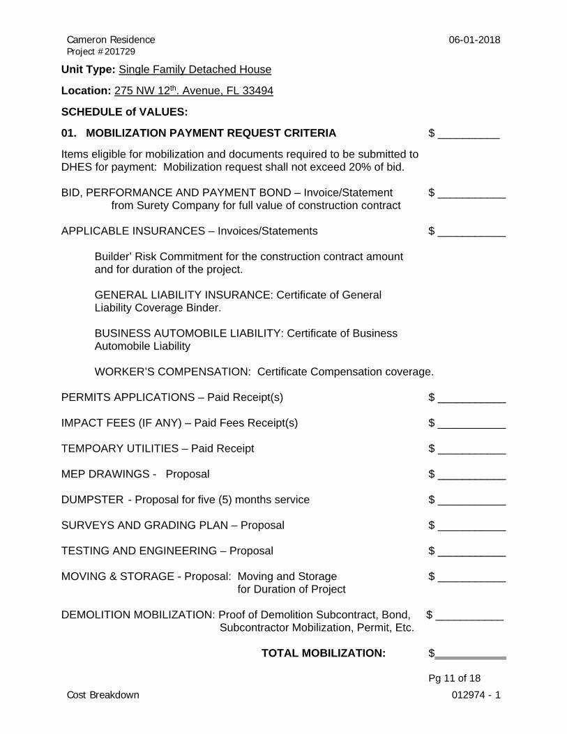
Cost Breakdown 012974 - 1
Unit Type: Single Family Detached House
Location: 275 NW 12th. Avenue, FL 33494
SCHEDULE of VALUES:
01. MOBILIZATION PAYMENT REQUEST CRITERIA $ __________
Items eligible for mobilization and documents required to be submitted to DHES for payment: Mobilization request shall not exceed 20% of bid. BID, PERFORMANCE AND PAYMENT BOND – Invoice/Statement $ ___________
from Surety Company for full value of construction contract
APPLICABLE INSURANCES – Invoices/Statements $ ___________ Builder’ Risk Commitment for the construction contract amount and for duration of the project. GENERAL LIABILITY INSURANCE: Certificate of General Liability Coverage Binder. BUSINESS AUTOMOBILE LIABILITY: Certificate of Business Automobile Liability WORKER’S COMPENSATION: Certificate Compensation coverage. PERMITS APPLICATIONS – Paid Receipt(s) $ ___________ IMPACT FEES (IF ANY) – Paid Fees Receipt(s) $ ___________ TEMPOARY UTILITIES – Paid Receipt $ ___________ MEP DRAWINGS - Proposal $ ___________ DUMPSTER - Proposal for five (5) months service $ ___________ SURVEYS AND GRADING PLAN – Proposal $ ___________ TESTING AND ENGINEERING – Proposal $ ___________ MOVING & STORAGE - Proposal: Moving and Storage $ ___________ for Duration of Project DEMOLITION MOBILIZATION: Proof of Demolition Subcontract, Bond, $ ___________ Subcontractor Mobilization, Permit, Etc. TOTAL MOBILIZATION: $ Pg 11 of 18

Cameron Residence Project #201729
06-01-2018
Cost Breakdown 012974 - 1
MOBILIZATION REQUEST CRITERIA: Not to Exceed 20% of Contract
NOTE #1: Contractor shall draw down portions mobilization items above after copies of permit applications are issued by the building department of jurisdiction and applicable documents required are received by PBCo. Dept of Economic Sustainability.
NOTE #2: Contractor shall request mobilization payment for long lead materials/components for “costs” excluding labor, profit & overhead, including - but not limited to the following:
LONG LEAD COMPONENTS 06100 ROOF TRUSSES - Proposal with order receipt and architect/engineer’s design approval.
081315 IMPACT RESISTANT RATED DOORS - Proposal with design, and Impact
Rating Notice of Acceptance.
85203 IMPACT RESISTANT RATED DOORS - Proposal with design, color and Impact Rating Notice of Acceptance
12300 CABINETRY AND COUNTER TOPS Proposal displaying color, finish and design.
Pg 12 of 18
Cameron Residence Project #201729
06-01-2018
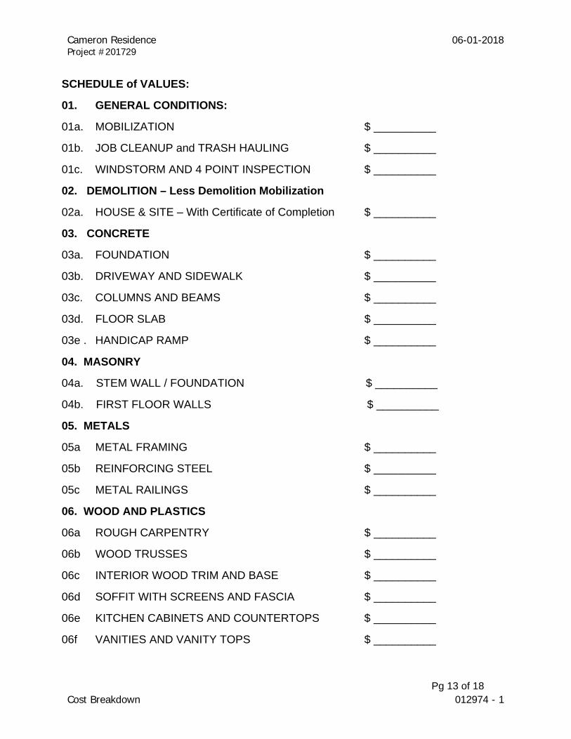
Cost Breakdown 012974 - 1
SCHEDULE of VALUES:
01. GENERAL CONDITIONS:
01a. MOBILIZATION $ __________
01b. JOB CLEANUP and TRASH HAULING $ __________
01c. WINDSTORM AND 4 POINT INSPECTION $ __________
02. DEMOLITION – Less Demolition Mobilization
02a. HOUSE & SITE – With Certificate of Completion $ __________
03. CONCRETE
03a. FOUNDATION $ __________
03b. DRIVEWAY AND SIDEWALK $ __________
03c. COLUMNS AND BEAMS $ __________
03d. FLOOR SLAB $ __________
03e . HANDICAP RAMP $ __________
04. MASONRY
04a. STEM WALL / FOUNDATION $ __________
04b. FIRST FLOOR WALLS $ __________
05. METALS
05a METAL FRAMING $ __________
05b REINFORCING STEEL $ __________
05c METAL RAILINGS $ __________
06. WOOD AND PLASTICS
06a ROUGH CARPENTRY $ __________
06b WOOD TRUSSES $ __________
06c INTERIOR WOOD TRIM AND BASE $ __________
06d SOFFIT WITH SCREENS AND FASCIA $ __________
06e KITCHEN CABINETS AND COUNTERTOPS $ __________
06f VANITIES AND VANITY TOPS $ __________
Pg 13 of 18
Cameron Residence Project #201729
06-01-2018
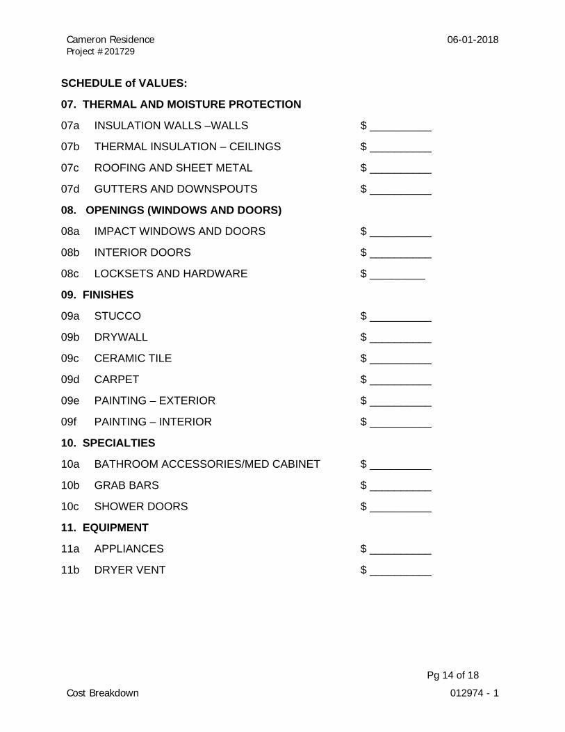
Cost Breakdown 012974 - 1
SCHEDULE of VALUES:
07. THERMAL AND MOISTURE PROTECTION
07a INSULATION WALLS –WALLS $ __________
07b THERMAL INSULATION – CEILINGS $ __________
07c ROOFING AND SHEET METAL $ __________
07d GUTTERS AND DOWNSPOUTS $ __________
08. OPENINGS (WINDOWS AND DOORS)
08a IMPACT WINDOWS AND DOORS $ __________
08b INTERIOR DOORS $ __________
08c LOCKSETS AND HARDWARE $ _________
09. FINISHES
09a STUCCO $ __________
09b DRYWALL $ __________
09c CERAMIC TILE $ __________
09d CARPET $ __________
09e PAINTING – EXTERIOR $ __________
09f PAINTING – INTERIOR $ __________
10. SPECIALTIES
10a BATHROOM ACCESSORIES/MED CABINET $ __________
10b GRAB BARS $ __________
10c SHOWER DOORS $ __________
11. EQUIPMENT
11a APPLIANCES $ __________
11b DRYER VENT $ __________
Pg 14 of 18

Cameron Residence Project #201729
06-01-2018
Cost Breakdown 012974 - 1
SCHEDULE of VALUES:
22. PLUMBING
22a SANITARY SEWER AND WATER CONNECTION $ __________
22b HOSE BIBBS $ __________
22c WATER HEATER $ __________
22d PLUMBING FIXTURES $ __________
23. HVAC – SPLIT SYSTEM
23a EQUIPMENT, DUCTWORK AND REGISTERS $ __________
23b RANGE HOOD EXHAUST FAN $ __________
26. ELECTRICAL
26a 150AMP PANELBOARD, CIRCUITRY $ __________
26b ELECTRICAL DEVICES $ __________
26c CEILING FANS $ __________
26d BATHROOM EXHAUST FANS $ __________
26e LIGHT FIXTURES $ __________
26f SMOKE DETECTORS $ __________
31. SITE IMPROVEMENTS
31a SITE GRADING $ __________
31b DE-MUCKING FILL AND COMPACTION $ __________
32. EXTERIOR IMPROVEMENTS
32a FLORATAM GRASS SOD $ __________
32b LANDSCAPING – TREES $ __________
TOTAL BID PROPOSAL $ _______________
Pg 15 of 18
Cameron Residence Project #201729
06-01-2018
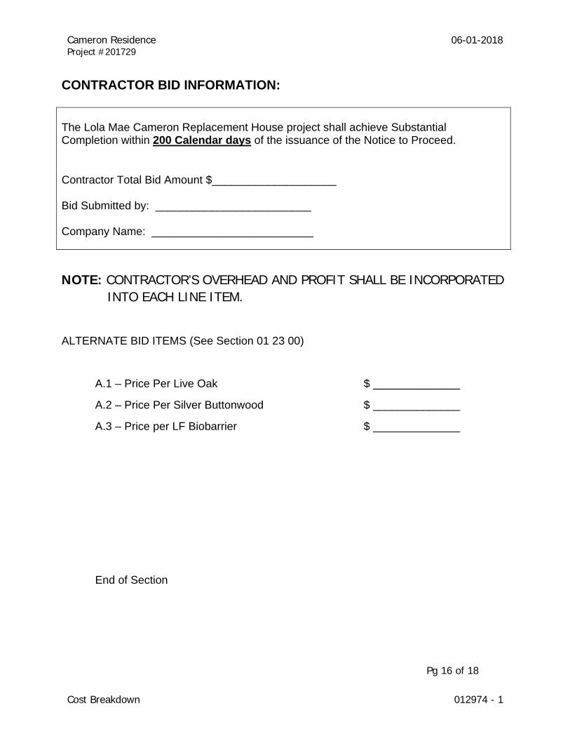
Cost Breakdown 012974 - 1
CONTRACTOR BID INFORMATION: The Lola Mae Cameron Replacement House project shall achieve Substantial Completion within 200 Calendar days of the issuance of the Notice to Proceed. Contractor Total Bid Amount $____________________ Bid Submitted by: _________________________ Company Name: __________________________
NOTE: CONTRACTOR’S OVERHEAD AND PROFIT SHALL BE INCORPORATED INTO EACH LINE ITEM.
ALTERNATE BID ITEMS (See Section 01 23 00)
A.1 – Price Per Live Oak $ ______________
A.2 – Price Per Silver Buttonwood $ ______________
A.3 – Price per LF Biobarrier $ ______________
End of Section
Pg 16 of 18
Cameron Residence Project #201729
06-01-2018
Cost Breakdown 012974 - 1
01 29 74 – COST BREAKDOWN: PAY APPLICATION FORMAT
A. GENERAL INFORMATION – There shall be six (6) pay applications
1. The apparent winning bidder shall provide the owner with a line item cost breakdown in AIA G702 and G703 or comparable pay request forms for pay requests within 5 calendar days of a request by DHES. PAY APPLICATION SUBMITTALS SHALL BE SCHEDULED AS FOLLOWING: Pay App #1 – Mobilization Allowances: After the construction contract and upon submitting documentation identified herein, the contractor shall request payment
of Mobilization not to exceed 20% of the construction bid. Pay App #2 – Demolition: Contractor shall submit a payment request within 5 calendar days of Final Acceptance of the Building Department of jurisdiction and any portion of construction progress. Pay Applications: Subsequent progress pay applications shall begin within thirty (30) days after the Construction Primary Building Permit is issued and shall be submitted monthly.
END OF SECTION Pg 17 of 18
Cameron Residence Project #201729
06-01-2018
Payment Procedures 012975 - 1
01 29 75 – PAYMENT PROCEDURES
A. GENERAL INFORMATION
1. Each application for payment shall be consistent with previous applications and payments as approved by the department. 2. Progress Payments: SEE 01 29 74 – COST BREAKDOWN: PAY APPLICATION FORMAT 3. Use AIA G702 and G703 or comparable pay request forms for pay requests. 4. Notarize and execute the form by a person authorized to sign legal documents on behalf of the contractor. 5. Entries shall match the information provided in the Schedule of Values or the Cost Breakdown supplied to the Department. 6. Contractor shall submit partial release of lien in the amount of pay request. 7. Prior to commencing construction, contractor shall apply for Mobilization Allowances and long lead components/items including - by not limited to the following:
a. Cabinetry and Counter Tops b. Impact Rated Doors c. Impact Rated Windows d. Roof Trusses
END OF SECTION Pg 18 of 18
Cameron Residence Project #201729
06-01-2018
Structural Shop Drawings 013301 - 1
01 33 01 STRUCTURAL SHOP DRAWINGS 1. GENERAL CONSTRUCTION 1. Shop drawings shall be prepared by Registered Engineers in Florida for concrete mix design, concrete reinforced steel, concrete masonry units, pre-engineered wood and light gauge metal trusses, light gauge metal framing, masonry reinforcing, structural steel, joists and deck, precast concrete, tilt walls, etc. 2. Submit all shop drawings for review to the engineer of record prior to any fabrication. 3. Shop drawings shall include erection plans, connections, member type and size with locations. 2. RELATED SPECIFICATION SECTION 1. Includes all items listed above.
END OF SECTION

Cameron Residence Project #201729
06-01-2018
Permits Required 014103-1
01 41 05 – PERMITS REQUIRED
A. GENERAL INFORMATION
The contractor shall apply for, pay for, obtain and forward copies of the following indicated permits and provide copies to the Dept. of Housing & Economic Sustainability within ten (10) calendar days of issuance: Building & Zoning Demolition Plumbing Electric HVAC END OF SECTION

Cameron Residence Project #201729
06-01-2018
Certificate of Occupancy 014106 - 1
01 41 06 – CERTIFICATE OF OCCUPANCY
A. GENERAL INFORMATION
Prior to final payment, the contractor shall comply with and complete all items necessary to receive a Certificate of Occupancy for the individual dwelling unit. END OF SECTION

Cameron Residence Project #201729
06-01-2018
Construction Definitions 014201 - 1
01 42 01 – CONSTRUCTION DEFINITIONS
A. GENERAL INFORMATION
1. “Owner” means the Homeowner. 2. "Install" means to purchase, set up, test and warrant a new component. 3. " Replace" means to remove and dispose of original material, purchase new material, deliver, install, test and warrant. 4. "Repair" means to return a building component to like new condition through replacement, adjustment and recoating of parts. 5. "Reinstall" means to remove, clean, store and install a component.
6. “Moving & Storage” means moving from the house and storing Off-Site at an insured remote location for duration of the project. After the Certificate of Occupancy has been issued by the Building Department of Jurisdiction, the contractor shall within ten (10) calendar days return items
placed in storage to the new house and place them as directed by the homeowner.
7. Substantial Completion: Identifies a date certain of construction completed to a stage where a Certificate of Occupancy has been issued which would permit the homeowner to begin arranging to occupy the house. The contractor, at this juncture may be undertaking completion of punch list items having been prepared by the project architect.
NOTE: DHES may in the best interests of the County extend the Substantial Completion date due to Acts of God, war, civil commotion, fire, flood or other casualty, shortages of materials or equipment, government regulations, unusually severe weather, or other causes beyond the contractor’s reasonable control.
END OF SECTION
Cameron Residence Project #201729
06-01-2018
Manufacturers Specifications Prevail 014301 - 1
01 43 01 – MANUFACTURER SPECIFICATIONS PREVAIL
A. GENERAL INFORMATION
All materials shall be installed in full accordance with the manufacturer's specifications for working conditions, surface preparation, methods, protection and testing. END OF SECTION
Cameron Residence Project #201729
06-01-2018
Demolition 017320 -
01 73 20 DEMOLITION
SITE SPECIFIC SCOPE OF WORK WET DEMOLITION
LOLA MAE CAMERON 275 NW 12TH. Avenue
South Bay, Florida 33493
This Site Specific Scope of Work applies only to the address listed above. Any item not specifically addressed in the Site Specific Scope of Work should be brought to the immediate attention of the Asbestos Consultant. The Asbestos Consultant will oversee the project and has the right to halt work if deemed not in compliance with the Site Specific Scope of Work.
Background:
DHES intends to provide funding assistance to the eligible applicant(s) listed above to enable the
demolition of their existing dwelling, and construction of a new replacement home on site. DHES
role also includes ensuring that activities undertaken during the project in conformance with all
applicable regulations.
Palm Beach County has opted to treat the entire structure as asbestos contaminated and require disposal of it as asbestos waste. The County will provide a consultant to oversee the wet demolition to ensure regulatory compliance. Consultant may require contractor to provide manifests or other documentation for review to ensure handling and disposal of all material meets all applicable regulatory requirements.
Note: There is no water or electric power available at the job site. The contractor is responsible for providing sufficient amounts of water to the site to comply with the NESHAP requirements for adequately wetting the material during demolition.
Qualifications:
The demolition contractor will have an OSHA competent person onsite during execution of the scope of work. All workers who will be involved in the physical loading of the material will be trained in accordance to the OSHA Asbestos Construction Standard for Class IV activity.
The Demolition contractor may subcontract the actual material handling and competent person responsibilities to a Florida Licensed Asbestos Abatement contractor provide the supervisors and workers meet or exceed the same training requirement.
The demolition contractor will provide copies of all training certificates for workers and supervisors to the Asbestos Consultant prior to the start of work.
Cameron Residence Project #201729
06-01-2018
Demolition 017320 -
Scope of work:
The contractor will remove and properly dispose of all building material down to bare earth as asbestos containing waste using the following procedure:
The demolition contractor will file a timely Notice of Asbestos Renovation or Demolition (NESHAP) from the local office of the Florida Department of Environmental Protection and provide a copy to the County’s designated Asbestos Coordinator and the Asbestos Consultant.
The demolition contractor will provide open top roll-off containers to the job site and line the interior of the containers with two layers of re-enforced plastic liners, a 10mil polyethylene dumpster liner or other material approved in advanced of the project by the Asbestos Consultant.
The liners will be large enough to cover the waste material in its entirety after loading.
All material will be adequately wet and remain wet until sealed in the roll off container.
After a container is properly loaded the material will be sealed by folding over excess plastic liner and securing it with spray glue and/or tape to create a water tight seal.
The material will be transported to a Class I landfill. An asbestos Waste Shipment Record (WSR) will accompany each load. A final report from the asbestos consultant company and copies of all WSR’s signed by the landfill operator will be returned to the County’s Asbestos coordinator within 35 days completion.
The County will not pay any invoices that are not accompanied by signed WSR’s.
The demolition contractor is responsible for complying with all local, state, and federal asbestos regulations (NESHAP, OSHA).
END OF SECTION

Cameron Residence Project #201729
06-01-2018
Dumpster 017419 - 1
01 74 19.03 DUMPSTER
A. General Information:
1. Location will vary per site.
B. Project Conditions:
1. Conditions will vary with each project.
C. Product:
1. Provide one 30 yard dumpster onsite for the period of time necessary to utilize it to legally dispose of all project waste.
D. Installation: N/A END OF SECTION

Cameron Residence Project #201729
06-01-2018
As Built Site Survey 017801 - 1
01 78 01 – AS-BUILT SITE SURVEY
A. GENERAL INFORMATION
1. Provide an "as built" survey verifying corner placement of all buildings and utility runs prior to final payment request.
END OF SECTION
Cameron Residence Project #201729
06-01-2018
Steps 033053 - 1
03 30 53 STEPS A. General Information:
1. See Section 03 10 01 FOUNDATIONS 2. See Section 03 30 00 CAST-IN-PLACE CONCRETE 3. See Section 05 52 00 METAL RAILINGS 4. See Section 06 10 00 ROUGH CARPENTRY 5. Field verify site conditions for steps ramp and landing locations. step design, handrails,
guardrails, width and general layout to meet the Florida Building Code 6th Edition 2017 or current building code and the 2017 Florida Accessibility Code for Building Construction or current accessibility code. General Contractor to provide permit and construction documents by a structural engineer.
B. Project Conditions:
1. Verify existing conditions on site.
C. Product:
1. Concrete Foundation, concrete pilings and/or wood pilings. D. Installation:
1. Install foundation.
2. Form and pour steps in equal heights and widths per building code. Steps to be 7” maximum height and 11” depth for 4 or more risers and 13” depth for 3 or fewer risers. Broom finish all concrete
3. Install railing support and railing per building codes.
END OF SECTION
Cameron Residence Project #201729
06-01-2018
Interior Wood Trim 062002 - 1
06 20 02 INTERIOR WOOD TRIM
A. General Information:
1. See Section 09 31 00 CERAMIC TILE.
2. See Section 09 91 00 PAINTING.
B. Project Conditions:
1. Do not install hardwood until the building is sealed and wet work is complete.
2. Provide moisture resistant wood trim when used in wet areas (bathrooms).
C. Products:
1. All Wood Trim to be paint-grade, finger-jointed pine.
2. All new wood trim installations to be as follows:
a. Door Trim Profile “M-21C” by Blumer and Stanton or approved equal.
Dimensions 5/8” x 2-5/8”
b. Base Trim: Profile B-9P” by Blumer and Stanton or approved equal. Dimensions 5/8” x 3-1/2”
3. All replacement trim to match existing profile.
D. Installation:
1. Groove or kerf back of flat trim
2. Back prime all wood trim in wet areas.
3. All joints to be beveled and sanded for smooth transitions between pieces
4. Fill all nail holes and joints with sandable, paintable wood filler.
5. Paint per specification requirements.
END OF SECTION
Cameron Residence Project #201729
06-01-2018
Rod and Shelf Interior Closet 062023 - 1
06 20 23 ROD AND SHELF INTERIOR CLOSET
A. General Information:
1. Provide blocking as required.
B. Project Conditions:
1. Prepare area for shelf and rod.
C. Products:
1. Wood Rod and Sockets: 1-1/2” pine rod. Provide metal support where distance be- tween bracing exceeds 5’.
2. Shelf: 12” x ¾” paint grade eastern white pine. Paint prior to installation.
D. Pine blocking: 2x4 paint grade eastern white pine. Paint prior to installation.
E. Installation:
1. Screw shelf to blocking.
2. Fasten to studs with screws. Conceal screw heads.
END OF SECTION

Cameron Residence Project #201729
06-01-2018
Thermal Insulation 072100 -
07 21 00 THERMAL INSULATION
A. General Information:
1. This section includes the following:
a. Batt insulation for walls and ceilings/attics. b. Rigid insulation on building exterior. c. Sound control blanket insulation in walls.
B. Project Conditions:
1 . Conditions vary with each project. In general, all insulation is to meet requirements of the Florida Building Code 6TH Edition 2017 and the Florida Building Code 6th
Edition: Energy Conservation 2017 or current building codes.
2. Provide insulating materials that comply with requirements and with referenced standards and, for preformed units, in sizes to fit applications indicated, selected from manufacturer's standard thicknesses, widths, and lengths.
3. Do not use paper-backed batt insulation.
C. Product:
1. Batt Insulation: a. Unfaced Mineral-Fiber Blanket Insulation: ASTM C 665, Type I; with maximum
flame-spread of not more than 25 and a smoke-developed index of no more than 450; passing ASTM E 136 for combustion characteristics. c. Faced Mineral-Fiber Blanket Insulation: ASTM C 665, Type III, Class A;
Category 1, faced with foil-scrim-kraft, foil scrim, or foil-scrim-polyethylene vapor- retarder membrane on one face, with maximum flame-spread of not more than
25 and a smoke-developed index of no more than 450; passing ASTM E 136 for combustion characteristics.
c. Minimum requirements: Floor – Minimum R-13 Wall Insulation – Minimum R-7 Ceiling/Attic insulation – Minimum R-38
2. Rigid Insulation - Extruded-Polystyrene Board Insulation: 1½” thick sheets of closed cell
polystyrene foam R-7 minimum. ASTM C 578, Type IV with maximum flame-spread and smoke-developed indexes of 75 and 450, respectively.
3. Sound Control Blanket Insulation - Shall be Type I Fiberglass Batts 3½” thick 2.5 pcf,
friction fit, for interior stud walls, with maximum flame-spread of not more than 25 and a smoke-developed index of no more than 450. Type as recommended by manufacturer for maximum sound attenuation.

Cameron Residence Project #201729
06-01-2018
Thermal Insulation 072100 -
D. Installation:
1. General: Install insulation to comply with insulation manufacturer's written instructions applicable to products and application indicated. Extend insulation in thickness indicated to envelop entire area to be insulated. Cut and fit tightly around obstructions and fill voids with insulation. Remove projections that interfere with placement.
2. Installation of General Building Insulation: Apply insulation units to substrates by meth- od indicated, complying with manufacturer's written instructions. If no specific method is indicated, bond units to substrate with adhesive or use mechanical anchorage to pro- vide permanent placement and support of units.
a. Seal joints between closed-cell (non-breathing) insulation units by applying ad- hesive, mastic, or sealant to edges of each unit to form a tight seal as units are shoved into place. Fill voids in completed installation with adhesive, mastic, or sealant. b. Set vapor-retarder-faced units with vapor retarder to warm side of construction,
unless otherwise indicated. Do not obstruct ventilation spaces, except for fire- stopping. Tape joints and ruptures in vapor retarder, and seal each continuous area of insulation to surrounding construction to ensure airtight installation.
c. Install mineral-fiber blankets in cavities formed by framing members according to the following requirements: 1. Use blanket widths and lengths that fill the cavities formed by framing mem-
bers. If more than one length is required to fill cavity, provide lengths that will produce a snug fit between ends.
2. Place blankets in cavities formed by framing members to produce a friction fit between edges of insulation and adjoining framing members.
3. For metal-framed wall cavities where cavity heights exceed 96 inches, support unfaced blankets mechanically and support faced blankets by taping stapling flanges to flanges of metal studs.
4. Install board insulation on concrete substrates by adhesively attached, spindle-type
insulation anchors as follows: a. Fasten insulation anchors to concrete substrates with insulation anchor adhesive
according to anchor manufacturer's written instructions. b. Apply insulation standoffs to each spindle to create cavity width indicated be-
tween concrete substrate and insulation. c. After adhesive has dried, install board insulation by pressing insulation into
position over spindles and securing it tightly in place with insulation-retaining washers, taking care not to compress insulation below indicated thickness.
d. Where insulation will not be covered by other building materials, apply capped washers to tips of spindles.
5. Stuff glass-fiber, loose-fill insulation into miscellaneous voids and cavity spaces where
shown. Compact to approximately 40 percent of normal maximum volume. END OF SECTION
Cameron Residence Project #201729
06-01-2018
ASPHALT SHINGLES 07311 - 1
SECTION 07 31 01 - ASPHALT SHINGLES
PART 1 - GENERAL
1.1 SUMMARY
A. This Section includes dimensional asphalt shingles for steep roofs. 1.2 SUBMITTALS
A. Product Data: For each product indicated.
B. Samples: Two full-size units for each asphalt shingle indicated and for each color and texture required.
1.3 QUALITY ASSURANCE
A. Fire-Test-Exposure Classification: Identify each bundle of shingles or shakes with appropriate markings indicating fire-test-exposure classification of testing and inspecting agency acceptable to authorities having jurisdiction.
B. Wind-Resistance-Test Characteristics: Identify each bundle of asphalt shingles with appropriate
markings indicating wind-resistance-test characteristics determined by a qualified testing and inspecting agency.
1. Wind Load Requirements: Ultimate Wind Speed VULT = 170 (Normal Wind Speed VASD = 132, Exposure C – Risk Category II as per 6th Edition Florida Building Code 2017, Section 1609.
C. Mockups: Build mockups to demonstrate aesthetic effects and qualities of materials and execution.
1. Build mockups as shown on drawings. 2. Approved mockups may become part of the completed Work if undisturbed at time of
Substantial Completion. 1.4 WARRANTY
A. Special Warranty: Manufacturer's standard form in which manufacturer agrees to furnish replacement shingles or refund pro-rata portion of amount originally paid for shingles that fail due to original product defects within 20 years from date of Substantial Completion. Failures include, but are not limited to, leaks or deformation or deterioration of asphalt shingles beyond normal weathering.
ASPHALT SHINGLES 07311 - 2
Cameron Residence Project #201729
06-01-2018
PART 2 - PRODUCTS
2.1 ASPHALT SINGLES
A. Available Products: Subject to compliance with requirements, products that may be incorporated into the Work include, but are not limited to, the following:
B. Products: Subject to compliance with requirements, provide one of the following:
1. GAF Building Materials Corporation. (Timberline – Royal Sovereign) or approved equal. 2. Celotex Corporation (The). 3. Certain Teed Corporation.
C. Colors, Blends, and Patterns: As selected from manufacturer's full range.
D. Fungus Resistance: Provide asphalt shingles surface treated to remain free of fungus and algae
growth, which adversely affects appearance of roof, for at least five years.
E. Three-Dimensional, Fiberglass, Laminated Strip Shingles: ASTM D 3018, Type I, and ASTM D 3462, mineral surfaced, self-sealing, laminated, multi-ply overlay construction, fiberglass based. 1. Wind Resistance: Passes requirements in ASTM D 3161. 2. Fire-Test-Response Classification: Class A per ASTM E 108.
F. Hip and Ridge Shingles: Factory-precut matching asphalt shingles.
2.2 METAL TRIM AND FLASHING
A. Sheet Metal Materials: 1. Aluminum: ASTM B 209
B. Metal Drip Edge: Brake-formed sheet metal with at least 2-inch roof deck flange and 1-1/2-
inch fascia flange with 3/8-inch drip at lower edge. Furnish in lengths of 8 or 10 feet
1. Material: Aluminum
C. Metal Flashing: Job-cut to sizes and configurations required. 1. Material: Aluminum
D. Open-Valley Metal Flashing: Preformed, inverted-V profile at center of valley and extending at
least 9 inches in each direction from centerline of valley.
1. Material: Aluminum
E. Vent Pipe Flashing: Lead, ASTM B 749, Type L51121, at least 1/16 inch thick, unless otherwise indicated. Provide lead sleeve sized to slip over and turn down into pipe, soldered to skirt at slope of roof extending at least 4 inches from pipe onto roof.
ASPHALT SHINGLES 07311 - 3
Cameron Residence Project #201729
06-01-2018
2.3 ACCESSORIES
A. Felt Underlayment: ASTM D 226 or ASTM D 4869, Type II (No. 30), 36-inch- wide, asphalt-
saturated organic felt or GAF Shingle- Mate with a head lap as required per the Florida Building Code 6th Edition 2017.
B. Asphalt Plastic Cement: Non-asbestos fibrated asphalt cement, complying with ASTM D 4586. C. Nails: Aluminum or hot-dip galvanized steel, 0.120-inch diameter barbed shank, sharp-pointed,
conventional roofing nails with minimum 3/8-inch diameter head and of sufficient length to penetrate 3/4 inch into solid decking or at least 1/8 inch through plywood sheathing. 1. Where nails are in contact with flashing, prevent galvanic action by providing nails made
from the same metal as that of flashing.
PART 3 - EXECUTION
3.1 PREPARATION
A. Clean substrates of projections and substances detrimental to application. Cover knotholes or other minor voids in substrate with sheet metal flashing secured with noncorrosive roofing nails.
B. Coordinate installation with flashings and other adjoining work to ensure proper sequencing.
Do not install roofing materials until all vent stacks and other penetrations through roof sheathing have been installed and are securely fastened against movement.
3.2 INSTALLATION
A. General: Comply with manufacturer's written instructions and recommendations but not less than those recommended by ARMA's "Residential Asphalt Roofing Manual" or NRCA's "The NRCA Steep Roofing Manual."
1. Proceed with installing asphalt shingles only when existing and forecasted weather
conditions will permit work to be performed according to manufacturers' written recommendations and warranty requirements, and when substrate is completely dry.
2. Fasten asphalt shingles to roof sheathing with nails.
B. Felt Underlayment: Apply 1 layer of felt underlayment horizontally over entire surface to receive asphalt shingles, lapping succeeding courses minimum of 2 inches, end laps minimum of 4 inches, and hips and valleys minimum of 6 inches. Secure felt with sufficient number of fasteners to hold underlayment in place until asphalt shingle installation. 1. Apply additional layer of felt underlayment on roof decks with slope
C. Waterproof Underlayment: Apply waterproof underlayment at eaves. Cover deck from eaves
to at least 24 inches inside exterior wall line.
1. In addition to eaves, apply waterproof underlayment in place of felt underlayment at valleys.
D. Underlayment at Closed Valleys: Center 36-inch wide felt underlayment in valley and secure
with only enough fasteners to hold in place until asphalt shingles are installed. Lap roof underlayment over valley underlayment at least 6 inches.

ASPHALT SHINGLES 07311 - 4
Cameron Residence Project #201729
06-01-2018
E. Metal Open Valleys: Comply with ARMA and NRCA recommendations. Install second felt
underlayment shingle lapped at least 12 inches and sealed with plastic asphalt cement. Install metal valley shingle lapped at least 9 inches and sealed with plastic asphalt cement.
F. Woven and Closed-Cut Valleys: Comply with ARMA and NRCA recommendations.
G. Flashing: Install metal flashing and trim as indicated and according to details and
recommendations in NRCA's "The NRCA Steep Roofing Manual."
H. Install asphalt shingles, beginning at roof's lower edge, with starter strip of roll roofing or inverted asphalt shingles with tabs removed. Fasten asphalt shingles in desired weather exposure pattern; use number of fasteners per shingle as recommended by manufacturer. Use vertical and horizontal chalk lines to ensure straight coursing.
1. Cut and fit asphalt shingles at valleys, ridges, and edges to provide maximum weather
protection. Provide same weather exposure at ridges as specified for roof. Lap asphalt shingles at ridges to shed water away from direction of prevailing wind.
2. Use fasteners at ridges of sufficient length to penetrate sheathing as specified.
I. Ridge Vents: Install according to manufacturer's written instructions
END OF SECTION

Cameron Residence Project #201729
06-01-2018
Exterior Door 081315 - 1
08 13 15 EXTERIOR DOOR – SOUND ATTENUATION REQUIRED
A. General Information:
1. See Section 09 91 00 PAINTING
2 See Section 06 20 02 INTERIOR WOOD TRIM
B. Project Conditions:
1. All exterior doors to be impact doors and must have hurricane protection to meet Florida Building Code, 6TH Edition 2017 or current applicable code requirements for product approval. Contractor to provide structural engineers calculation for the applicable door load requirements for site specific conditions. All provided doors must meet the required psf.
2. Door to be minimum 36” width.
C. Products:
1. Door: Impact resistant steel door and frame assembly Steel All Panel Exterior Door by Jen-Weld or approved equal with Florida Product Approval.
2. Lever hardware with keyed deadbolt; must match impact approved door hardware.
3. Install peephole at 4’-10” AFF (not required if vision panel is provided in the door).
3. Provide weather stripping, door stop or chain and threshold
D. Installation:
1. Install doors per manufacturer’s recommendations.
2. Paint per approved color selection 3. Provide level 5’ x 5’ landing at door. 4. Acoustical treatment:
A. Contractor shall use a high-density expanding foam sealant around the entire perimeter of the door frame to seal the door assembly and minimize air/noise infiltration. This is a Mandatory Inspection item and DES rehab inspector shall be notified 24 hours in advance of such inspection.
B. Contractor shall use an acoustical sealant for exposed joints, non-sag, paintable, non-staining latex sealant complying with ASTM C-834.
END OF SECTION
Cameron Residence Project #201729
06-01-2018
Interior Prehung Door 081700 - 1
08 17 00 INTERIOR PREHUNG DOOR
A. General Information:
1. See Section 09 91 00 PAINTING
2. See Section 06 20 02 INTERIOR WOOD TRIM INTERIOR
3. See Section 08 70 01 LOCKSET - INTERIOR
B. Project Conditions:
1. Door to be minimum 32” clear opening (34” width door).
C. Products:
1. Door: premium grade, medium density overlay 1-3/8” hollow core wood door.
2. Shop prime faces and edges of doors with one coat of wood primer. See paint specification.
3. Flush flat door panel construction or to match existing door panels
4. Door to have blocking to eliminate through bolting hardware.
5. Hardware: All interior bedroom and bathroom doors to have privacy lever locksets. Provide 3 satin nickel finish hinges.
D. Installation:
1. Install doors per manufacturer’s recommendations.
2. Verify door swing required prior to ordering door assembly.
END OF SECTION

Cameron Residence Project #201729
06-01-2018
Single Hung Aluminum Windows 085203 - 1
08 52 03 SINGLE HUNG ALUMINUM WINDOWS – SOUND ATTENUATION REQUIRED
A. GENERAL INFORMATION
1. Impact windows to meet Florida Building Code, 6TH edition 2017 requirements for product approval. Contractor to provide structural engineers calculation for the applicable window load requirements for site specific conditions. All provided windows must meet the required psf. Reinforce framing and fill adjacent cells, sills and heads to meet requirements of structural engineer.
2. All bedrooms to have a door or operable window that meets egress window requirements. Verify with window supplier that each bedroom has a window that meets these requirements.
3. See Section 04 81 00 UNIT MASONRY ASSEMBLY
4. See Section 06 10 00 ROUGH CARPENTRY
5. See Section 07 21 00 THERMAL INSULATION
6. See Section 07 46 01 FIBER CEMENT SIDING
7. See Section 09 22 00 PORTLAND CEMENT PLASTER
8. See Section 09 29 00 GYPSUM BOARD
9. See Section 09 91 00 PAINTING
B. PROJECT CONDITIONS
1. Coordinate all window rough opening requirements prior to commencement of masonry work.
C. PRODUCTS
1. Impact Windows: PGT Winguard, SH700 with laminated insulating glass or approved equal. Single-hung, aluminum windows, with insect screens. Units to have U-Value minimum .65, SHGC min .25.
D. INSTALLATION
1. In Masonry Construction: Fill cells as required by structural engineer and product approval requirements
2. Install windows per manufacturer’s recommendations and to form a watertight installation with drip at head.
3. Acoustical treatment:
A. Contractor shall use a high-density expanding foam sealant around the entire perimeter of the window frame to seal the window assembly and minimize air/noise infiltration. This is a Mandatory Inspection item and DES rehab inspector shall be notified 24 hours in advance of such inspection.
B. Contractor shall use an acoustical sealant for exposed joints, non-sag, paintable, non-staining latex sealant complying with ASTM C-834.
END OF SECTION
Cameron Residence Project #201729
06-01-2018
Lockset - Interior 087001 - 1
08 70 01 LOCKSET - INTERIOR
A. General Information:
1. See Section 08 00 00 OPENINGS
B. Products:
1. General Use:
a. Bedroom and bath: Schlage Lever Lockset model F40 FLA or approved equal.
b. Closet and hall: Schlage Lever Lockset model F10 FLA or approved equal.
c. Non-operational (dummy) interior door: Schlage Lever Lockset model F170 FLA or approved equal d. Finish to be from standard color and finish selections. Architect to se- lect/approve during shop drawing review.
C. Installation:
1. Install as per manufacturer’s recommendations.
END OF SECTION
Cameron Residence Project #201729
06-01-2018
Portland Cement Plaster 092200 - 1
09 22 00 PORTLAND CEMENT PLASTER
A. General Information:
1. See Section o4 20 00 MASONRY
2. See Section 06 10 00 ROUGH CARPENTRY
3. See Section 06 40 01 STRUCTURAL WALL SHEATHING
4. See Section 09 91 00 PAINTING
B. Project Conditions: 1. Install mockups to verify selections made under sample Submittals and to demonstrate aesthetic effects and qualities of materials and execution.
2. Approved mockups may become part of the completed Work if undisturbed at time of Substantial Completion.
3. Comply with requirements of referenced plaster application standards and recommenda- tions of plaster manufacturer for environmental conditions before, during, and after plaster application.
C. Products:
1. Expanded-Metal Lath: ASTM C 847.
a. Material: Zinc-coated (galvanized) steel sheet, structural quality, with coating complying with ASTM A 653/A 653M, G60 coating designation. b. Diamond-Mesh Lath: Self-furring. Weight: 3.4 lb/sq. yd. c. Rib Lath: Flat, rib depth of not more than 1/8 inch. Weight: 3.4 lb/sq. yd. d. Backing: Where lath is indicated to have backing, and where backing is required for machine application of plaster; provide self-furring lath backed with asphalt felts on solid gypsum sheathing.
2. Plaster materials:
a. Base-Coat Cements: Portland cement, ASTM C 150, Type I b. Job-Mixed Finish-Coat Cement: Portland cement, ASTM C 150, Type I. Cement Color: Gray. c. Lime: Special non air-entraining hydrated lime for finishing purposes, ASTM C 206, Type S; or special non air-entraining hydrated lime for masonry purposes, ASTM C 207, Type S. d. Sand Aggregate for Base Coats: ASTM C 897. e. Aggregate for Finish Coats: ASTM C 897 system, and as indicated below. Manufactured or natural sand, white in color.
Portland Cement Plaster 092200 - 2
Cameron Residence Project #201729
06-01-2018
4. Miscellaneous Materials:
a. Fiber for Base Coat in Three-Coat Work: Alkaline-resistant glass or poly- propylene fibers, 1/2 inch long, free of contaminates, manufactured for use in Portland cement plaster. b. Water for Mixing and Finishing Plaster: Potable. c. Bonding Agent: A non-re-emulsifiable acrylic emulsion. Approved prod- ucts include Thoroseal/Acryl 60, manufactured by Harris Specialty Chemicals, Inc.: Xycrylic, manufactured by Xypec Chemical Corp.: and Sikalatex, manufac- tured by Sika Chemical Corp. d. Acid-Etching Solution: Muriatic acid (10 percent solution of commercial hydrochloric acid) mixed 1 part to not less than 6 nor more than 10 parts water. e. Asphalt-Saturated Felt: ASTM D 226, Type I (No. 15), nonperforated.
5. Plaster Mixes and Compositions:
a. Comply with ASTM C 926 for base – and finish-coat mixes as applicable to plaster bases, materials, and other requirements indicated, except that plastic cement and masonry cement not permitted. b. Base-Coat Mixes and Compositions: Proportion materials for respective base coats in parts by volume for cementitious materials and in parts by volume of aggregate per sum of cementitious materials to comply with the following re- quirements for each method of application and plaster base indicated. Adjust mix proportions below within limits specified to attain workability. c. Fiber Content: Add fiber to brown coat of three-coat mixes after ingredi- ents have mixed for at least 2 minutes. Comply with fiber manufacturer’s written instructions, but do not exceed 1 lb/cu. ft. of cementitious materials. Reduce aggregate quantities accordingly to maintain workability. d. Three-Coat Work over Metal Lath: Base-coat proportions as indicated below:
1. Scratch Coat: 1 part portland cement, 0 to 3/4 parts lime, 2-1/2 to 4 parts sand. 2. Brown Coat: 1 part portland cement, 0 to 3/4 parts lime, 3 to 5 parts sand.
e. Two-Coat Work over Concrete Unit Masonry: Base coat proportions as indi- cated below:
1 part portland cement, 3/4 to 1-1/2 parts lime, 3 to 4 parts sand. Water to be mixed with bonding admixture in proportion as recommended by admixture manufacturer.
f. Job-Mixed Finish Coats: Proportion materials for finish coats in parts by vol- ume for cementitious materials and parts by volume of aggregates per sum of cementitious materials to comply with the following requirements:
1. Proportions using sand aggregates as indicated below: 1 part portland cement, ¾ to 1-1/2 parts lime, 3 parts sand.
6. Lath and Furring Installation:
a. Install supplementary framing, blocking, and bracing at terminations in work and for support of fixtures, equipment services, heavy trim, grab bars, handrails, furnishings, and similar work to comply with details indicated or, if not
Portland Cement Plaster 092200 - 3
Cameron Residence Project #201729
06-01-2018
otherwise indicated, to comply with applicable written instructions of lath and furring manufacturer. b. Where lathing and metal support system abut building structure horizon- tally and where partition or wall abuts overhead structure, isolate from structural movement to prevent transfer of loading from building structure. Frame both sides of control joints independently and do not bridge joints with furring and lathing or accessories. c. Install additional framing, furring, runners, lath, and beads, as required to form openings and frames for other work as indicated. Coordinate support sys- tem for proper support of framed work that is not indicated to be supported in- dependently of metal furring and lathing system.
7. Non-Load-Bearing Framing Installation: a. Ceiling Suspension Systems:
1. Preparation and Coordination: Coordinate installation of ceiling suspen- sion system with installation of overhead structural systems to ensure inserts and other structural anchorage provisions have been installed to receive ceil- ing hangers in a manner that will develop their full strength and at spacings required to support ceiling. 2. Hanger Installation: Comply with ML/SFA 920, "Guide Specifications for Metal Lathing and Furring," and with referenced standards.
3. Do not attach hangers to metal deck tabs. b. Install ceiling suspension system components of sizes and spacings indi- cated, but not in smaller sizes or greater spacings than those required by refer- enced lathing and furring installation standards.
8. Lathing:
a. Install where plaster base coats are required. Provide appropriate type, configuration, and weight of metal lath selected from materials indicated that comply with referenced ML/SFA specifications and ASTM lathing installation standards. b. Suspended and Furred Ceilings: Use flat, diamond-mesh lath.
9. Preparations for Plastering:
a. Protect contiguous Work from damage and deterioration caused by plas- tering with temporary covering and other provisions necessary. b. Clean plaster bases and substrates for direct application of plaster, re- moving loose material and substances that may impair the Work. c. Etch concrete and concrete unit masonry surfaces indicated for direct plas- ter application. Scrub with acid-etching solution on previously wetted surface and rinse thoroughly with clean water. Repeat application, if necessary, to ob- tain adequate suction and mechanical bond of plaster (where dash coat, bonding agent, or additive is not used). d. Apply bonding agent on concrete and concrete unit masonry surfaces in- dicated for direct plaster application. e. Apply dash coat on concrete surfaces indicated for direct plaster applica- tion. Moist-cure dash coat for at least 24 hours after application and before plas- tering.
Portland Cement Plaster 092200 - 4
Cameron Residence Project #201729
06-01-2018
f. Install temporary grounds and screeds to ensure accurate rodding of plaster to true surfaces; coordinate with scratch-coat work. g. Immediately before plastering, dampen concrete and concrete unit ma- sonry substrates, except where a bonding agent has been applied, to produce optimum suction for plastering.
10. Plaster Application:
a. Mixing: Mechanically mix cementitious and aggregate materials for plas- ters to comply with applicable referenced application standard and with recom- mendations of plaster manufacturer. b. Do not use materials that are frozen, caked, lumpy, dirty, or contaminat- ed by foreign materials. c. Do not use excessive water in mixing and applying plaster materials. d. Flat Surface Tolerances: Do not deviate more than plus or minus 1/8 inch in 10 feet from a true plane in finished plaster surfaces, as measured by a 10-foot straightedge placed at any location on surface. e. Sequence plaster application with installation and protection of other work so that neither will be damaged by installation of other. f. Plaster flush with metal frames and other built-in metal items or accesso- ries that act as a plaster ground, unless otherwise indicated. Where interior plaster is not terminated at metal frame by casing beads, cut base coat free from metal frame before plaster sets and groove finish coat at junctures with metal. g. Make internal corners and angles square; finish external corners flush with corner beads on interior work, square and true with plaster faces on exterior work. h. Number of Coats:
1. Metal Lath: Three coats. 2. Concrete Unit Masonry: Two coats. 3. Concrete, Cast-in-Place or Precast: Two coats when surface condition complies with ASTM C 926 for plaster bonded to solid base.
i. Finish Coats: 1. Float Finish: Apply finish coat to a minimum thickness of 1/8 inches to completely cover base coat, uniformly floated to a true even plane with fine-textured finish matching sample. 2. Trowel-Textured Finish: Apply finish coat with hand-troweled-extured finish matching sample.
j. Terminations of Plaster: Install casing beads, unless otherwise indicated. k. Control Joints: Install at locations indicated or, if not indicated, at locations
complying with the following criteria and approved by Architect: 1. Where an expansion or contraction joint occurs in surface of construction directly behind plaster membrane. 2. Distance between Control Joints: Not to exceed 18 feet in either direction or a length-to-width ratio of 2-1/2 to 1. 3. Wall Areas: Not more than 144 sq. ft. 4. Horizontal Surfaces: Not more than 100 sq. ft. in area. 5. Where plaster panel sizes or dimensions change, extend joints full width or height of plaster membrane.
Portland Cement Plaster 092200 - 5
Cameron Residence Project #201729
06-01-2018
11. Cutting, Patching, and Cleaning:
a. Cut, patch, replace, repair, and point up plaster as necessary to accom- modate other work. Repair cracks and indented surfaces. Point-up finish plaster surfaces around items that are built into or penetrate plaster surfaces. Repair or replace work to eliminate blisters, buckles, check cracking, dry outs, efflo- rescence, excessive pinholes, and similar defects. Repair or replace work as necessary to comply with required visual effects. b. Remove temporary covering and other provisions made to minimize spat- tering of plaster on other work. Promptly remove plaster from doorframes, win- dows, and other surfaces not to be plastered. Repair surfaces stained, marred or otherwise damaged during plastering work.
END OF SECTION
Cameron Residence Project #201729
06-01-2018
Wall and Ceiling Drywall 0092905 - 1
09 29 05 WALL AND CEILING DRYWALL
A. General Information:
1. See Section 09 91 23 PAINTING. 2. See Section 09 29 00 GYPSUM BOARD FINISH.
B. Project Conditions:
1. Protect all product prior to and during installation.
C. Products: 1. Drywall shall be 5/8” thick at ceiling and ½” thick at walls with maximum lengths and widths available to minimize joints in each area and correspond with existing sup- port system.
2. In areas with fire rated assemblies, all new material will meet requirements of fire rated assemblies.
D. Installation:
1. Install gypsum panels across framing to minimize the number of abutting end joints. Stagger abutting end joints of adjacent panels not less than one framing member.
2. Install gypsum panels with face side out. Butt panels with not more than 1/16 inch of open space between panels. Do not force into place.
3. Do not place gypsum panel tapered edges against cut edges or ends.
4. Install gypsum panels to supports with steel drill screws at 12 inches on center.
5. Treat gypsum board joints, interior angles, edge trim, control joints, penetrations, fastener heads, surface defects, and elsewhere as required to prepare gypsum board surface for paint finish.
6. Prefill open joints and damaged surface areas. Patch drywall as required using 3 coat finishing process.
7. Apply joint tape over gypsum board joints, except those with trim having flanges not intended for tape.
8. Prepare for painting finish and paint surface as per section 09 91 23 PAINTING.
END OF SECTION
Cameron Residence Project #201729
06-01-2018
Porcelain Tile – PT3 093011 - 1
09 30 11 – PORCELAIN TILE – PT3
A. GENERAL INFORMATION
1. See section 01 10 02 OWNERS FINISH SELECTION.
B. PROJECT CONDITIONS
1. Substrate to be smooth and meet requirements of per TCNA (Tile Council of North America) handbook.
C. PRODUCTS
1. 12 x 12 Colorbody porcelain tile – Cliff Pointe – or approved equal. Tile to be slip resistant.
2. 12 x 6 Cove Base Trim
D. INSTALLATION
1. Install ceramic tile floor per TCNA (Tile Council of North America) handbook and manufacturer installation guidelines.
2. Installation to be centered in room each way. Trim tile as needed to fit in existing space.
3. Provide cove base to match floor or to match wall tile.
END OF SECTION

Cameron Residence Project #201729
06-01-2018
Ceramic Tile at Shower/Tub 093102 - 1
09 31 02 CERAMIC TILE AT SHOWER/TUB
A. GENERAL INFORMATION
1. See Section 06 10 00 ROUGH CARPENTRY 2. See Section 07 21 00 THERMAL INSULATION 3. See Section 09 29 00 GYPSUM BOARD ASSEMBLIES 4. See Section 09 91 00 PAINTING. 5. See Section 10 28 02 CERAMIC TILE ACCESSORIES 6. See Section 01 10 02 OWNERS FINISH SELECTION
B. PROJECT CONDITIONS
1. Pitch to drain.
C. PRODUCTS
1. All drywall in bathrooms to be cementious board.
2. Shower pan liner: 40 mil PVC Oatley or approved equal
3. Ceramic Tile: 4x4 ceramic tile – dal tile or approved equal – price group 1 or 2 with tile accessories at corners and bullnose at top. Extend shower/tub tile to 7’ aff mini- mum. Matte finish tile at floor to meet ADA slip resistance requirements.
4. Bathroom Accessories – Ceramic shelf, shower rod and ceramic soap dish
D. INSTALLATION
1. Slope shower floor substrate or slab using leveling compound
2. Install shower pan per manufacture’s recommendations.
3. Construct shower walls per the permitted plans.
4. Install ceramic tile and accessories. Install ceramic tile per TCNA (Tile Council of North America) handbook and manufacturer installation guidelines.
5. Finish cementious board and paint.
END OF SECTION
Cameron Residence Project #201729
06-01-2018
Porcelain Tile – PT1 and PT2 093112 - 1
09 31 12 – PORCELAIN TILE – PT1 AND PT2
A. GENERAL INFORMATION
1. See Section 062000 - INTERIOR WOOD TRIM
2. See Section 01 10 02 OWNERS FINISH SELECTION.
B. PROJECT CONDITIONS
1. Protect adjacent surfaces
2. Substrate to be smooth and meet requirements of the TCNA handbook.
C. PRODUCTS
1. 12 x 12 Colorbody porcelain tile – Cliff Pointe – or approved equal. Tile to be slip resistant.
2. Grout to match tile.
3. Porcelain or wood base – coordinate with finish schedule.
D. INSTALLATION
1. Install ceramic tile floor per TCNA (Tile Council of North America) handbook and manufacturer installation guidelines.
2. Installation based on full size tiles and to extend at least 12” past door jambs or to adjacent wall and 12” past open door. Use full tiles.
END OF SECTION
Cameron Residence Project #201729
06-01-2018
Vinyl Composition Tile 096520 - 1
09 65 20 – VINYL COMPOSITION TILE
A. GENERAL INFORMATION
1. No base at Utility Room. See finish schedule.
B. PROJECT CONDITIONS
1. Substrate to be smooth and meet requirements of sheet vinyl manufacturer.
C. PRODUCTS
1. Armstrong - Standard Excelon Imperial Texture 12x12 vinyl tile.
2. Adhesive must comply with Rule 1168 of the South Coast Air Quality Management District.
D. INSTALLATION
1. Install vinyl composition tile per manufacturer’s recommendations. END OF SECTION
Cameron Residence Project #201729
06-01-2018
Painting 099100 - 1
09 91 00 PAINTING
A. General Information:
1. See Section 09 29 00 GYPSUM BOARD ASSEMBLIES.
B. Project Conditions:
1. Surface Preparation: Clean and prepare surfaces to be painted according to manufac- turer's written instructions for each particular substrate condition and as specified. Provide barrier coats over incompatible primers or remove and re-prime. 2. Interior:
a. Lightly sand surface and patch wall surface prior to paint application. b. Prepare surfaces for painting with Krud Kutter or approved equal - non-toxic, biodegradable cleaning agent where required. c. Clear room and cover all surfaces prior to beginning work. d. Apply waterborne paint when temperature is between 50 degrees – 90 degrees.
3. Exterior: a. Pressure clean with water, fill all cracks and holes. b. Lightly sand surface and patch wall surface prior to paint application. c. Apply waterborne paint when temperature is between 50 degrees – 90 degrees.
4. Cementitious Materials: Remove efflorescence, chalk, dust, dirt, grease, oils, and re- lease agents. Roughen as required to remove glaze. If hardeners or sealers have been used to improve curing, use mechanical methods of surface preparation.
5. Wood: Clean surfaces of dirt, oil, and other foreign substances with scrapers, mineral spirits, and sandpaper, as required. Sand surfaces exposed to view smooth and dust off. Scrape and clean small, dry, seasoned knots, and apply a thin coat of white shellac or other recommended knot sealer before applying primer. After priming, fill holes and im- perfections in finish surfaces with putty or plastic wood filler. Sand smooth when dried.
6. Ferrous Metals: Clean ungalvanized ferrous-metal surfaces that have not been shop coated; remove oil, grease, dirt, loose mill scale, and other foreign substances. Use sol- vent or mechanical cleaning methods that comply with SSPC's recommendations. Blast steel surfaces clean as recommended by paint system manufacturer and according to SSPC-SP 6/NACE No. 3. Treat bare and sandblasted or pickled clean metal with a metal treatment wash coat be- fore priming. Touch up bare areas and shop-applied prime coats that have been dam- aged. Wire-brush, clean with solvents recommended by paint manufacturer, and touch up with same primer as the shop coat.
C. Products: All paint and primers must meet the most recent Green Seal G-11 Environmental standards.
1. Manufacturers' Names a. Benjamin Moore & Co. (Benjamin Moore). b. M. A. Bruder & Sons, Inc. (M. A. B. Paint). c. Sherwin-Williams Co. (Sherwin-Williams).
2. Preparatory Coats:
Cameron Residence Project #201729
06-01-2018
Painting 099100 - 2
a. Concrete Unit Masonry Block Filler: High-performance latex block filler of finish coat manufacturer and recommended in writing by manufacturer for use with finish coat and on substrate indicated. b. Exterior Primer: Exterior alkyd or latex-based primer of finish coat manufacturer and recommended in writing by manufacturer for use with finish coat and on sub- strate indicated.
1. Ferrous-Metal and Aluminum Substrates: Rust-inhibitive metal primer. 2. Zinc-Coated Metal Substrates: Galvanized metal primer. 3. Where manufacturer does not recommend a separate primer formulation on substrate indicated, use paint specified for finish coat.
c. Interior Primer: Interior latex-based or alkyd primer of finish coat manufacturer and recommended in writing by manufacturer for use with finish coat and on sub- strate indicated.
1. Ferrous-Metal Substrates: Quick drying, rust-inhibitive metal primer. 2. Zinc-Coated Metal Substrates: Galvanized metal primer. 3. Where manufacturer does not recommend a separate primer formula- tion on substrate indicated, use paint specified for finish coat.
3. Exterior Finish Coats:
a. Exterior Low-Luster Acrylic Paint:
1. Benjamin Moore; Moorcraft Super Spec Low Lustre Latex House Paint No. 185. 2. M. A. B. Paint; Fresh Kote Latex Eggshell 405 Line. Sherwin-Williams; A-100 Exterior Latex Satin House & Trim Paint A82 Series.
b. Exterior Full-Gloss Acrylic Enamel for Ferrous and Other Metals:
1. Benjamin Moore; Moore's IMC Acrylic Gloss Enamel M28. 2. M. A. B. Paint; Rust-O-Lastic Gloss Acrylic (DTM) Maintenance Finish 043 Line. 3. Sherwin-Williams; DTM Acrylic Coating Gloss (Waterborne) B66W100 Series.
c. Exterior Full-Gloss Alkyd Enamel:
1. Benjamin Moore; Moore's IMC Urethane Alkyd Enamel M22. 2. M. A. B. Paint; Rust-O-Lastic Finish Coating 074 Line. 3. Sherwin-Williams; Industrial Enamel B-54 Series.
4. Interior Finish Coats:
a. Interior Low-Luster Acrylic Enamel:
1. Benjamin Moore; Moorcraft Super Spec Latex Eggshell Enamel No. 274.
2. M. A. B. Paint; Fresh Kote Latex Satin Eggshell Enamel 405 Line. 3. Sherwin-Williams; ProMar 200 Interior Latex Egg-Shell Enamel
B20W200 Series.
Cameron Residence Project #201729
06-01-2018
Painting 099100 - 3
b. Interior Semigloss Acrylic Enamel:
1. Benjamin Moore; Moorcraft Super Spec Latex Semi-Gloss Enamel No. 276.
2. M. A. B. Paint; Fresh Kote Latex Semi-Gloss 410 Line. 3. Sherwin-Williams; ProMar 200 Interior Latex Semi-Gloss Enamel
B31W200 Series.
5 Interior Wood Stains and Varnishes: a. Open-Grain Wood Filler:
1. Benjamin Moore; Benwood Paste Wood Filler No. 238. 2. M. A. B. Paint; Paste Wood Filler. 3. Sherwin-Williams; none recommended.
b. Interior Wood Stain: Alkyd based.
1. Benjamin Moore; Benwood Penetrating Stain No. 234. 2. M. A. B. Paint; Wood Stain 062 Line. 3. Sherwin-Williams; Wood Classics Interior Oil Stain A-48 Series.
c. Clear Sanding Sealer: Fast-drying alkyd based.
1. Benjamin Moore; Moore's Interior Wood Finishes Quick-Dry Sanding Sealer No. 413. 2. M. A. B. Paint; Minit Dri Sanding Sealer 037-005 Line. 3. Sherwin-Williams; Wood Classics Fast Dry Sanding Sealer B26V43.
d. Interior Alkyd- or Polyurethane-Based Clear Satin Varnish:
1. Benjamin Moore; Benwood Interior Wood Finishes Polyurethane Fin- ishes Low Lustre No. 435. 2. M. A. B. Paint; Rich Lux Water Based Satin Polyurethane. 3. Sherwin-Williams; Wood Classics Fast Dry Oil Varnish, Satin A66- 300 Series.
D. Installation:
1. Surface Preparation: Clean and prepare surfaces to be painted according to manu- facturer's written instructions for each particular substrate condition and as specified. 2. Provide barrier coats over incompatible primers or remove and reprime. 3. Cementitious Materials: Remove efflorescence, chalk, dust, dirt, grease, oils, and release agents. Roughen as required to remove glaze. If hardeners or sealers have been used to improve curing, use mechanical methods of surface preparation. 4. Wood: Clean surfaces of dirt, oil, and other foreign substances with scrapers, miner- al spirits, and sandpaper, as required. Sand surfaces exposed to view smooth and dust off. 5. Ferrous Metals: Clean ungalvanized ferrous-metal surfaces that have not been shop coated; remove oil, grease, dirt, loose mill scale, and other foreign substances. Use sol- vent or mechanical cleaning methods that comply with SSPC's recommendations.
6. Galvanized Surfaces: Clean galvanized surfaces with nonpetroleum-based solvents so surface is free of oil and surface contaminants. Remove pretreatment from galva- nized sheet metal fabricated from coil stock by mechanical methods.
Cameron Residence Project #201729
06-01-2018
Painting 099100 - 4
7. Apply paint materials no thinner than manufacturer's recommended spreading rate. Provide total dry film thickness of the entire system as recommended by manufacturer.
8. Prime Coats: Before applying finish coats, apply a prime coat, as recommended by manufacturer, to material that is required to be painted or finished and that has not been prime coated by others. Recoat primed and sealed surfaces where evidence of suction spots or unsealed areas in first coat appears, to ensure a finish coat with no burn-through or other defects due to insufficient sealing.
9. Pigmented (Opaque) Finishes: Completely cover surfaces as necessary to provide a smooth, opaque surface of uniform finish, color, appearance, and coverage. Cloudiness, spotting, holidays, laps, brush marks, runs, sags, ropiness, or other surface imperfec- tions will not be acceptable.
10. Transparent (Clear) Finishes: Use multiple coats to produce a glass-smooth surface film of even luster. Provide a finish free of laps, runs, cloudiness, color irregularity, brush marks, orange peel, nail holes, or other surface imperfections.
11. Cleanup:
a. At the end of each workday, remove empty cans, rags, rubbish, and other dis- carded paint materials from Project site. b. Protect work of other trades, whether being painted or not, against damage from painting. Correct damage by cleaning, repairing or replacing, and repainting, as ap- proved by Architect. c. After work of other trades is complete, touch up and restore damaged or de- faced painted surfaces.
EXTERIOR PAINT SCHEDULE
1. Concrete, Stucco, and Masonry (Other Than Concrete Unit Masonry):
a. Acrylic Finish: Two finish coats over a primer. 1. Primer: Exterior concrete and masonry primer. 2. Finish Coats: Exterior low-luster acrylic.
2. Concrete Unit Masonry:
a. Acrylic Finish: Two finish coats over a block filler. 1. Block Filler: Concrete unit masonry block filler. 2. Finish Coats: Exterior low-luster acrylic paint.
3. Smooth Wood:
a. Acrylic Finish: Two finish coats over a primer. 1. Primer: Exterior wood primer for acrylic. 2. Finish Coats: Exterior semigloss acrylic.
4. Wood Trim:
a. Acrylic-Enamel Finish: Two finish coats over a primer. 1. Primer: Exterior wood primer for acrylic enamels.
2. Finish Coats: Exterior semigloss acrylic.
Cameron Residence Project #201729
06-01-2018
Painting 099100 - 5
5. Plywood:
a. Acrylic Finish: Two finish coats over a primer. 1. Primer: Exterior wood primer for acrylic. 2. Finish Coats: Exterior low-luster acrylic.
6. Ferrous Metal: a. Acrylic Finish: Two finish coats over a rust-inhibitive primer.
1. Primer: Exterior ferrous-metal primer (not required on shop-primed items. 2. Finish Coats: Exterior semigloss acrylic.
7. Zinc-Coated Metal:
a. Acrylic Finish: Two finish coats over a galvanized metal primer. 1. Primer: Exterior galvanized metal primer. 2. Finish Coats: Exterior full-gloss acrylic enamel for ferrous and other metals.
8. Aluminum:
a. Acrylic-Enamel Finish: Two finish coats over a primer. 1. Primer: Exterior aluminum primer under acrylic. 2. Finish Coats: Exterior full-gloss acrylic enamel for ferrous and other metals.
INTERIOR PAINT SCHEDULE
1. Concrete and Masonry (Other Than Concrete Unit Masonry):
a. Acrylic Finish: Two finish coats over a primer. 1. Primer: Interior concrete and masonry . 2. Finish Coats: Interior low-luster acrylic enamel .
2. Concrete Unit Masonry:
a. Acrylic Finish: Two finish coats over a block filler. 1. Block Filler: Concrete unit masonry block . 2. Finish Coats: Interior low-luster acrylic enamel.
3. Gypsum Board:
a. Acrylic Finish: Two finish coats over a primer. 1. Primer: Interior gypsum board primer . 2. Finish Coats: Interior low-luster acrylic enamel .
4. Plaster:
a. Acrylic Finish: Two finish coats over a primer. 1. Primer: Interior plaster . 2. Finish Coats: Interior low-luster acrylic enamel.
Cameron Residence Project #201729
06-01-2018
Painting 099100 - 6
5. Ferrous Metal:
a. Acrylic Finish: Two finish coats over a primer. 1. Primer: Interior ferrous-metal primer . 2. Finish Coats: Interior semigloss acrylic enamel.
INTERIOR STAIN AND NATURAL-FINISH WOODWORK SCHEDULE
1. Stain-Varnish Finish: Two finish coats of varnish over a sealer coat and interior wood stain. Wipe wood filler before applying stain. Applied at spreading rate recommended by manufacturer. a. Filler Coat: Open-grain wood filler. b. Stain Coat: Interior wood stain. c. Sealer Coat: Clear sanding sealer. d. Finish Coats: Interior alkyd- clear satin varnish.
2. Natural-Varnish Finish: Two finish coats of varnish over a sealer coat and a filler
coat. Applied at spreading rate recommended by manufacturer. a. Filler Coat: Open-grain wood filler. b. Sealer Coat: Clear sanding sealer. c. Finish Coats: Interior alkyd- clear satin varnish.
END OF SECTION
Cameron Residence Project #201729
06-01-2018
Knock Down Finish 099172 - 1
09 91 72 KNOCK DOWN FINISH
A. General Information:
1. See Section 09 29 00 GYPSUM BOARD ASSEBLIES
2. See Section 09 91 00 PAINTING.
B. Project Conditions:
1. When installing gypsum board substrate, provide in maximum lengths and widths available that will minimize joints.
C. Products:
1. Gypsum substrate: regular 5/8” gypsum board.
2. One-component gypsum veneer plaster for application directly over gypsum board with use of separate base-coat material – United State Gypsum Co, Diamond Interior Finish Plaster or approved equal.
3. Obtain plaster products, including gypsum base, joint reinforcing tape, embedding material and plasters from a single manufacturer. Use materials that are recommended by the manufacturer.
D. Installation:
1. Reinforce interior angles and flat joints with joint tape and embedding material to comply with plaster manufacturer’s recommendations.
2. Mechanically mix gypsum veneer plaster materials.
3. Provide knock down textured finish.
4. In existing conditions, paint existing ceiling to match new white ceiling color.
END OF SECTION
Cameron Residence Project #201729
06-01-2018
Bathroom Accessories 102800 - 1
10 28 00 - BATHROOM ACCESSORIES
A. GENERAL INFORMATION
1. Each bathroom to have the following Bathroom Accessories:
(1) robe hook
(2) 24” long towel bars
(1) soap dish at sink
(1) mirror 24 x 36 minimum
(1) toilet paper holder
With a shower or bath
(1) soap dish with washcloth hold at tub or shower
(1) bath or shower shelf
B. PROJECT CONDITIONS
1. Provide blocking for all accessories
C. PRODUCTS
1. Standard Bathroom Accessories: provide listed manufacturer or approved equal
robe hook – Kohler Forte Double Sculpted Robe Hook – Mounting Height: 52” aff
24” long towel bars – Kohler Coralais 24” towel bar in Polished Chrome - Mount- ing Height: 48” aff
soap dish at sink – Kohler Devonshire Soap Dish in Polished Chrome - Mounting Height: 42” aff
mirror – frameless, full length of vanity - Mounting Height: above sink
toilet paper holder – Kohler Coralais wall mount double post toilet paper holder - Mounting Height: 19” aff
With a shower or bath
(1) soap dish with washcloth hold at tub or shower – Dal Tile BA725 - Mounting Height: 16” aff
(1) bath or shower shelf – Dal Tile BA725 - Mounting Height: 48” aff
2. Ceramic Bathroom Accessories: Based on Dal Tile:
soap dish by sink – BA725
soap dish with washcloth holder – BA728
corner shelves – BA725
towel bar brackets - BA730

Cameron Residence Project #201729
06-01-2018
Bathroom Accessories 102800 - 2
D. INSTALLATION
1. Install accessories based on manufactures recommendations level and plumb.
2. Patch any damaged adjacent surfaces. END OF SECTION
Cameron Residence Project #201729
06-01-2018
Mailboxes 112900 - 1
11 29 00 MAILBOXES
A. General Information:
1.See structural drawings for Cast-In Place Concrete B. Project Conditions:
1. Locate per drawings.
C. Product:
1. Provide a standard size mailbox, where applicable wall-hung at the entrance or the mailbox placed on a post at the street in accordance with any HOA requirements if applicable. 2. Mailboxes shall comply with US Postal Service requirements.
3. Post and Mail Box: “Lowes, Whitehall 10.125” x 53” metal white ground mailbox with post.
D. Installation:
1. Install mailboxes securely as per manufacturer's recommendations.
END OF SECTION
Cameron Residence Project #201729
06-01-2018
11 31 00 UNDERCOUNTER DISHWASHER - ENERGY STAR
A. General Information:
Undercounter Dishwasher – Energy Star 113100 - 1
1. See drawings for casework details.
B. Project Conditions:
1. Coordinate dishwasher size and location with cabinet manufacturer.
C. Products:
1. General Use: General Electric Co built-in dishwasher, model no GLDT690JWW – col- or white, or approved equal sized to replace 24” unit with hot air, and heat off drying cycles, sliding dish racks and removable silverware basket, UL rated.
D, Installation:
1. Securely anchor to supporting cabinetry or countertop with concealed fasteners. Verify that clearances are adequate for proper functioning and rough openings are com- pletely concealed.
2. Verify 30”x48” working area compliant with Fair Housing Requirements in front of or with a side approach to the dishwasher.
END OF SECTION
Cameron Residence Project #201729
06-01-2018
Refrigerator – Energy Star 113101 - 1
11 31 01 REFRIGERATOR - ENERGY STAR
A. General Information:
1. Plumbing contractor to coordinate for water distribution, drainage, vent piping and plumbing fixtures.
2. Electrical contractor to coordinate all electrical services and connections to residential appliances.
B. Project Conditions:
1. Coordinate refrigerator size and location with cabinet manufacturer.
C. Product:
1. General Use: GE Refrigerator, model no GTE21GSHSS – frost free, 20.0 Cu. Ft., En- ergy Star rated with top mounted freezer, spill resistant shelves, fresh door bins, fresh food bins with adjustable humidity drawers and an ice maker, UL listed or approved equal.
D. Installation:
1. Place in final location after finishes have been completed in each area. Verify that clearances are adequate to properly operate equipment.
2. Connect appliance to plumbing connections. Refer to product’s owner manual for proper installation.
END OF SECTION
Cameron Residence Project #201729
06-01-2018
Disposal 113105 - 1
11 31 05 DISPOSAL A. General Information:
1. Plumbing contractor to coordinate all water distribution, drainage, vent piping and plumbing fixtures.
2. Electrical contractor to coordinate all electrical services and connections to residential appliances.
B. Project Conditions:
1. Install to minimize impact on under cabinet storage.
C. Product:
1. General Use: General Electric 1 Horsepower Continuous Feed Disposer, model no GFC1020V or approved equal.
D. Installation:
1. Connect appliance to plumbing and electrical connections. Refer to product’s owner manual for proper installation.
END OF SECTION
Cameron Residence Project #201729
06-01-2018
Electric Range 113107 - 1
11 31 07 ELECTRIC RANGE A. General Information:
1. Electrical contractor to coordinate all electrical services and connections to
residential appliances.
B. Project Conditions:
1. Coordinate range size and location with cabinet manufacturer.
C. Product:
1. General Use: General Electric 30” Free Standing Electric Range, model no JBP35DM or approved similar.
2. Owner shall select color from manufacturer’s full range of colors.
D. Installation:
1. Place in final location after finishes have been completed in each area. Verify that clearances are adequate to properly operate equipment.
2. Make all necessary connections to make range operable in accordance with the Residential Florida Building Code 2017 or current applicable building code.
END OF SECTION
Cameron Residence Project #201729
06-01-2018
Range Hood Ductless 113111 - 1
11 31 11 RANGE HOOD/MICROWAVE OVEN COMBINATION vented through the roof A. General Information:
1. Electrical contractor to coordinate all electrical services and connections to residential appliances.
B. Project Conditions:
1. Coordinate hood size and location with cabinet manufacturer.
C. Product:
1. General Use: General Electric 30" Over-the-Range Microwave/Exhaust Fan with 1.6 cu. ft. Capacity.
2. Owner shall select color from manufacturer’s full range of colors.
D. Installation:
1. Securely anchor to supporting cabinetry or countertops with concealed fasteners. Verify that clearances are adequate for proper functioning and rough openings are completely concealed.
2. Make all necessary connections to make range hood operable in accordance with the Residential Florida Building Code 2017 or current applicable building code.
END OF SECTION

Cameron Residence Project #201729
06-01-2018
Washing Machine Stainless Steel 113112 - 1
11 31 12 WASHING MACHINE STAINLESS STEEL A. General Information:
1. Plumbing contractor to coordinate all water distribution, drainage, vent piping and plumbing fixtures.
2. Electrical contractor to coordinate all electrical services and connections to residential appliances.
C. Product:
1. General Use: General Electric Energy Star 4.5 DOE Cu. Ft. Capacity Frontload Wash- er with Stainless Steel Basket, model no GFW430SSMWW or approved similar.
2. Owner shall select color from manufacturer’s full range of colors.
D. Installation:
1. Place in final location after finishes have been completed in each area. Verify that clearances are adequate to properly operate equipment.
2. Connect appliance to plumbing and electrical connections. Refer to product’s owner manual for proper installation.
END OF SECTION
Cameron Residence Project #201729
06-01-2018
Drying Machine 113113 - 1
11 31 13 ELECTRIC LAUNDRY DRYING MACHINE A. General Information:
1. Electrical contractor to coordinate all electrical services and connections to residential appliances.
B. Product:
1. General Use: General Electric GTD42EASJ 7.2 Cu. Ft., 4 heat selections, Aluminized alloy drum, Wrinkle Care extended tumble, and End-of-cycle signal or approved similar.
2. Owner shall select color from manufacturer’s full range of colors.
C. Installation:
1. Place in final location after finishes have been completed in each area. Verify that clearances are adequate to properly operate equipment.
2. Connect appliance electrical connections. Refer to product’s owner manual for proper installation.
END OF SECTION