Camera Cage Construction Manual - ccom.unh.edu · UNIVERSITY OF NEW HAMPSHIRE – CENTER OF COASTAL...
40
UNIVERSITY OF NEW HAMPSHIRE – CENTER OF COASTAL AND OCEAN MAPPING Camera Cage Construction Manual Center of Coastal and Ocean Mapping Designed and Constructed by: Paul Lavoie Manual Written and Compiled by: Tim Brown and Matthew Birkebak Reviewed by: Shachak Pe’eri and Emily Terry Camera cage manual (CCOM/JHC)
Transcript of Camera Cage Construction Manual - ccom.unh.edu · UNIVERSITY OF NEW HAMPSHIRE – CENTER OF COASTAL...

UNIVERSITY OF NEW HAMPSHIRE – CENTER OF COASTAL AND OCEAN MAPPING
Camera Cage Construction Manual
Center of Coastal and Ocean Mapping
Designed and Constructed by: Paul Lavoie Manual Written and Compiled by: Tim Brown and Matthew Birkebak
Reviewed by: Shachak Pe’eri and Emily Terry
Camera cage manual (CCOM/JHC)

1
Preface
The Center for Coastal and Ocean Mapping uses a camera cage underwater video camera system with real-time feedback to ground-truth survey measurements. The underwater imaging system designed to perform in situ measurements that help calibrate and validate optical remote-sensing and swath-sonar surveys for mapping and monitoring coastal ecosystems and ocean planning. The system enables researchers to collect underwater imagery using relatively inexpensive instruments and materials that can be hand-deployed from a small vessel. This document is the first manual out of two that describes the design of the cage of the camera. The second manual describes the camera systems and procedures to capture imagery.

2
Contents
Bill of Materials ....................................................................................................................................... 3
Locations of Camera Cage Parts ............................................................................................................. 8
Tools Required ...................................................................................................................................... 12
Construction ......................................................................................................................................... 12
Bottom of Camera Cage ................................................................................................................... 12
Gather Materials........................................................................................................................... 12
Machine Parts to Specifications ................................................................................................... 12
Assemble Bottom Components .................................................................................................... 16
Top of Camera Cage ......................................................................................................................... 19
Gather Materials........................................................................................................................... 19
Machine Parts to Specifications ................................................................................................... 21
Assemble Top Components .......................................................................................................... 23
Combine middle and top .................................................................................................................. 26
Gather Components ..................................................................................................................... 26
Assembling Top and Bottom ........................................................................................................ 27
Cage Carrying Assembly ................................................................................................................... 28
Gather Materials........................................................................................................................... 28
Assembly ....................................................................................................................................... 29
Camera (Electrical Components) ............................................................. Error! Bookmark not defined.
Electronics Bill of Material ................................................................... Error! Bookmark not defined.
Assemble Electrical Components ........................................................ Error! Bookmark not defined.
Appendix ............................................................................................................................................... 32

3
Bill of Materials
Camera Cage Bottom Components
# Part Name Picture Reference to Buy
Price Each
Purchase Quantity
Physical Quantity
1
Type 304 Smooth-Bore Seamless SS
Tubing 1/2" OD, .43" ID, .035" Wall, 6'
Length
Figure 1 - McMaster Carr
McMaster Carr Reference number:
89895K744
$31.65
1 (need 4x~12” rods)
4 rods of length 20”
2
SS Swagelok Tube Fitting, Union
Elbow, 1/2 in. Tube OD
Figure 2 - Swagelok
Swagelok Part Number: SS-810-9
$32.30 4 4
3 Multipurpose 304
Stainless Steel Bar 1/4" X 1/2", 3' Long
Figure 3 - McMaster Carr
McMaster Carr Reference number: 8992K504
$14.03 1 (need
4x 9” bars)
4 bars of 1/4” x 1/2"
X 9”
4 Multipurpose 304
Stainless Steel Bar 1/8" X 1", 2' Long
Figure 4 - McMaster Carr
McMaster Carr Reference number: 8992K133
$7.77 2 (need 4x12” bars)
4 bars of 1/8" X 1" X
11.625”
5
18-8 SS Round Head Phillips Machine
Screw 6-32 Thread, 5/16" Length, Packs
of 100
Figure 5 - McMaster Carr
McMaster Carr Reference number:
91773A145
$3.69 1
(Need 12)
12
6
18-8 SS Round Head Phillips Machine
Screw 8-32 Thread, 5/8" Length, Packs of
100
Figure 6 - McMaster Carr
McMaster Carr Reference number:
91773A196
$5.66 1 (need
8) 8

4
Camera Cage Middle Components
7
SS Swagelok Tube Fitting, Male
Connector, 3/8 in. Tube OD x 1/8 in.
Male NPT
Figure 7 - Swagelok
Swagelok Part Number: SS-600-1-2
$8.80 4 4
8
Type 304 Smooth-Bore Seamless SS
Tubing 3/8" OD, .277" ID, .049" Wall, 6'
Length
Figure 8 - McMaster Carr
McMaster Carr Reference number:
89895K738
$31.65 2 4 rods of
length 11.4”
9
SS Swagelok Tube Fitting, Male
Connector, 3/8 in. Tube OD x 1/4 in.
Male NPT
Figure 9 - Swagelok
Swagelok Part Number: SS-600-1-4
$9.90 4 4
Camera Cage Top Components
10a
White Delrin ® Acetal Resin Sheet, 3/4"
Thick, 12" x 12" ( If using this sheet the model will be slightly
smaller than the 14”x14” first model
therefore all dimensions presented
would need to be resized)
Figure 10 - McMaster Carr
McMaster Carr Reference number: 8573K21
$67.67 1 1 sheet 14”X
14”
10b
White Delrin ® Acetal Resin Sheet, 3/4" Thick, 24" x 24"
Figure 10 – McMaster Carr
McMaster Carr Reference number: 8573K81
$217.50 1 Machine to 1
sheet 14”x14”
11
Type 304 Stainless STL Threaded Pipe Fitting 1/4 Pipe Size, Hex Head Plug, 150
PSI Figure 11 - McMaster Carr
McMaster Carr Reference number: 4464K252
$2.00 4 4

5
12
Corrosion-Resistant Eyebolt for Lifting
W/Shoulder, 316SS, 1/4"-20 Thrd Size, 1"
Lg Thrd
Figure 12 - McMaster Carr
McMaster Carr Reference number: 8891T72
$11.28 4 4
13
Type 18-8 Stainless Steel Hex Nut, 1/4"-20 Thread Size, 7/16" Wide, 7/32" High (Pack of 100)
Figure 13 - McMaster Carr
McMaster Carr Reference number:
91845A029
$4.64 1 6
14
Multipurpose Type 304 Stainless Steel 90 Degree Angle,
1/4" Thick, 3" x 4" Leg Lengths 6”
Figure 14 - McMaster Carr
McMaster Carr Reference number: 1260T56
$36.49 1 1, 2.5” X 3.5” X 3.5” (could
be larger)
15
18-8 Stainless Steel Hex Head Cap Screw
1/4"-20 Thread, 1" Long, Fully Threaded,
Packs of 50
Figure 15 - McMaster Carr
McMaster Carr Reference number:
92240A542
$6.93 1 2
16
18-8 Stainless Steel Hex Head Cap Screw
1/4"-20 Thread, 3-1/2" Long, Packs of
10 Figure 16 - McMaster Carr
McMaster Carr Reference number:
92198A556
$4.06 1 2
17 Go Pro Quick Release Mount
Figure 17 - Go Pro Quick Release Mount
http://shop.gopro.com/mounts/curved-plus-flat-adhesive-
mounts/AACFT-
001.html#/start=1
$19.99 1 1
18 Camera Mount
Included in Camera Package
- 1 1

6
19 Stainless steel
bracket (Handle)
Custom made - 1 1
Cage Carrying Components
20
Type 316 SS High-Strength Anchor
Shackle with Screw Pin, 7/16" Diameter, 2000# Work Load
Limit
Figure 18 - McMaster Carr
McMaster Carr Reference number: 3583T83
$19.21 5 5
21
Stainless Steel Load-Rated Wire Rope Lanyard Coated,
Loop/Loop, 1/8" Rope Diameter, 1' Length
Figure 19 - McMaster Carr
McMaster Carr
Reference number:
30745T436
$21.78 4 4
22
Stainless Steel Load-Rated Wire Rope Lanyard Coated,
Loop/Loop, 1/8" Rope Diameter, 3' Length
Figure 20 - McMaster Carr
McMaster Carr
Reference number:
30745T436
$29.72 1 1
23
Double Loop Cable-Support Grip
Corrosion Resistant, Midcable, 0.5"-0.61"
Cable Dia
Figure 21 - McMaster Carr
McMaster Carr
Reference Number: 70095K71
$54.51 1 1
Camera Electrical Components
# Part Name Picture Reference to Buy
Price Each
Purchase Quantity
Physical Quantity
24 Ocean Systems Delta
Vision Hi Definition (HD)
http://www.
sea-~$2100
1 or 0
Buy Either HD or STD

7
Figure 22- www.sea-viewdiving.com
viewdiving.com/diving_equipment/cameras/oceansystems/deltavisionhd.ht
m
25
Ocean Systems Delta Vision
Standard Definition (STD)
Figure 23 - www.sea-viewdiving.com
http://www.sea-
viewdiving.com/diving_equipment/cameras/oceansystems/deltavisioncolor.
htm
- 1 or 0 Buy Either HD or STD
26 GoPro Hero3+ Silver
Figure 24 - GoPro
http://shop.gopro.com/cameras/hero
3plus-silver/CHDH
N-302-master.html
$299.99 1 1
27 Elgato Game Capture
HD
Figure 25 - Elgato
https://www.elgato.com/en/gaming/gamecapture-
hd
$149.95 1 1

8
Locations of Camera Cage Parts
Figure 26 -Overall Camera Cage with locations of detailed views
A B
C
D

9
Figure 27 - Detail View A, The number in each balloon corresponds to the part number in the bill of materials
Figure 28 - Detail View B, The number in each balloon corresponds to the part number in the bill of materials
2 1
7
8
4 5
6 3 2
7
8
1

10
Figure 29 - Detail View C, The number in each balloon corresponds to the part number in the bill of materials
12
11
9
8
13 10 17
18
13
Figure 30 - Detail View D, The number in each balloon corresponds to the part number in the bill of materials
16
14
15
11
22
21
20
23 attached
at end
20
Figure 32 - Detail View showing cage carrying components. The number in each balloon corresponds to the part number in the bill of materials
19
Figure 31 - Top of Camera Cage with Metal Handle
15

12
Tools Required
1. Table or Band saw 2. A method of sanding Delrin 3. At least 2 wrench’s for Swagelok components (Adjustable is the best) 4. Drill that can penetrate stainless Steel 304 with a .5” diameter and much smaller hole (Can be a
drill press. 5. Funnel (to insert lead shot into 3/8” tubing) 6. 1/4” NPT tap and a 1/8” NPT tap 7. hacksaw
Construction
Bottom of Camera Cage
The bottom assembly is put together first.
Gather Materials
1. Gather materials from the bill of materials listed under bottom components or alternate components of same size and material from a different vendor.
# Part Name Reference to Buy Price Each Quantity
1 Type 304 Smooth-Bore Seamless SS Tubing 1/2" OD, .43" ID,
.035" Wall, 6' Length McMaster Carr Reference
number: 89895K744
$31.65
1 (need 4 rod of length 12”)
2 SS Swagelok Tube Fitting, Union Elbow, 1/2 in. Tube
OD
Swagelok Part Number:
SS-810-9 $32.30 4
3 Multipurpose 304 Stainless Steel Bar 1/4" X 1/2", 3' Long McMaster Carr Reference
number: 8992K504 $14.03
1 (need 4 bars of length 9”)
4 Multipurpose 304 Stainless Steel Bar 1/8" X 1", 2' Long McMaster Carr Reference
number: 8992K133 $7.77
2 (need 4 bars of length 11.625””)
5 18-8 SS Round Head Phillips Machine Screw 6-32 Thread,
5/16" Length, Packs of 100 McMaster Carr Reference
number: 91773A145 $3.69 1 (Need 12)
6 18-8 SS Round Head Phillips Machine Screw 8-32 Thread, 5/8"
Length, Packs of 100 McMaster: 91773A196 $5.66 1 (need 8)
Middle Camera Cage Components
7 SS Swagelok Tube Fitting, Male Connector, 3/8 in. Tube OD x
1/8 in. Male NPT Swagelok Part Number:
SS-600-1-2 $8.80 4
Machine Parts to Specifications
2. Once all Components are gathered they must be cut and custom machined to the specifications provided in the following steps (All dimensions in inches):
a. ½” ss tubing: i. Use machine to cut 6’ of ½” stainless steel tubing into 4 rods of length 11.4”.
NOTE: For rod to sit in fully to both union elbows the length would need to be 11.4475”.

13
ii. Set stainless steel tubing in a rig and drill two holes with a #29 drill bit (.1360”) in the ½” tubing spaced 5” apart, centered both length and width wise in all 4 rods.
iii. Use an 8-32 tap to create threads in all the holes on each ½” ss tubing. Keep tapping until the tap extends .125” past other side of tubing unless tap is not long enough. (May need carbide or stronger tap and die set for use with 304 stainless steel). NOTE: Tubing should be tapped from Bottom to Top.
Figure 33 - working drawing 1/2" ss tubing
b. 304 Bar ¼” X ½”X 9”: i. Use a machine to cut 3’ 304 stainless steel bar into 4 bars of length 9”.
ii. Secure piece and drill two holes with a #29 drill bit (.1360”) in the bar 2” from the left side and 7” from the left side.
iii. Use an 8-32 tap to create threads in the holes with a diameter of .1360”. They should be tapped to a depth of .125”. NOTE: Should be tapped Bottom to Top.
iv. Secure piece and drill three holes with a # 35 drill bit (.11”) in the bar 1” from left side, 4.5” from left side, and 8” from left side.
v. Use a 6-32 tap to create threads in the holes with a diameter of .11”. NOTE: These should be tapped starting on the opposite side as the 8-32 tap. Or should be tapped Top to Bottom
vi. Repeat steps b. 2-5 with all four 9” bars.
Figure 34 - working drawing 304 ss bar
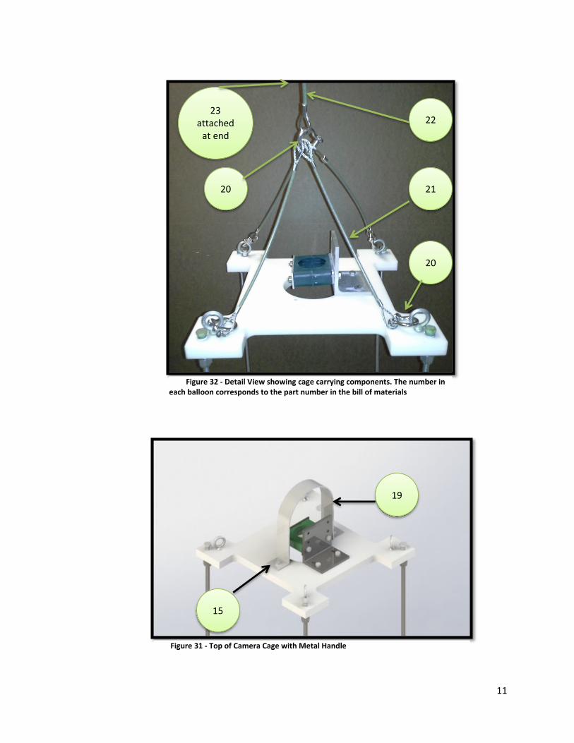
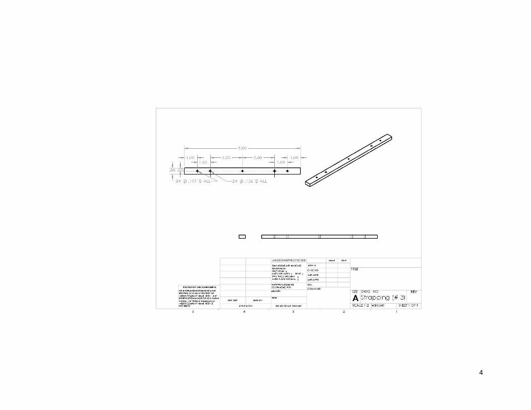
c. 304 Bar 1/8” X 1”X11.625”: i. Use a machine to cut 6’ 304 stainless steel bar into 4 bars of length 11.625”.
ii. Secure piece and drill three holes with a # 35 drill bit (.11”) in the bar 2.31” from left side, 7.81” from left side, and 9.315” from left side.
iii. Use a 6-32 tap to create threads in the holes with a diameter of .11”. NOTE: Tap Top to Bottom
iv. Sand corners with to a .15” fillet
14
v. Repeat steps 2-4 with all four 11.625” bars.
Figure 35 - working drawing 304 ss powder coated bar
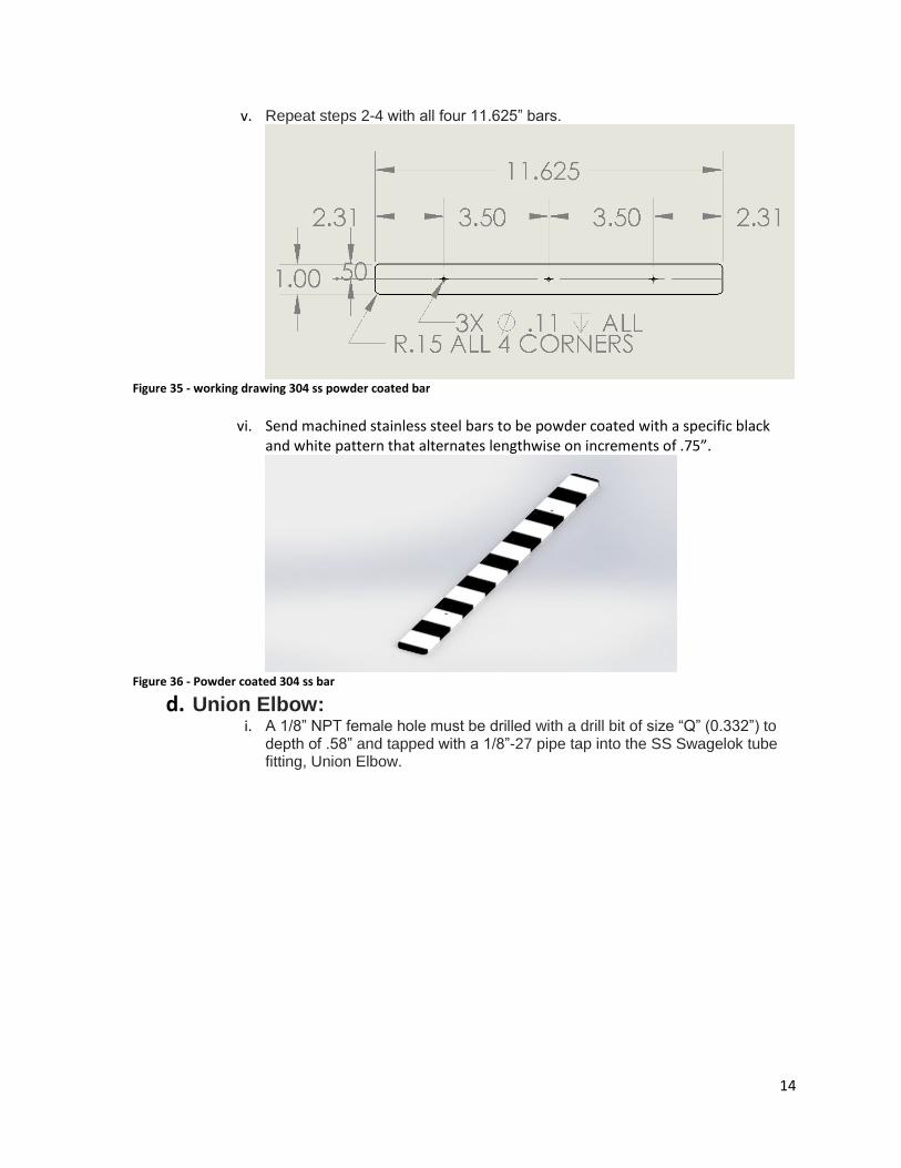
vi. Send machined stainless steel bars to be powder coated with a specific black
and white pattern that alternates lengthwise on increments of .75”.
Figure 36 - Powder coated 304 ss bar
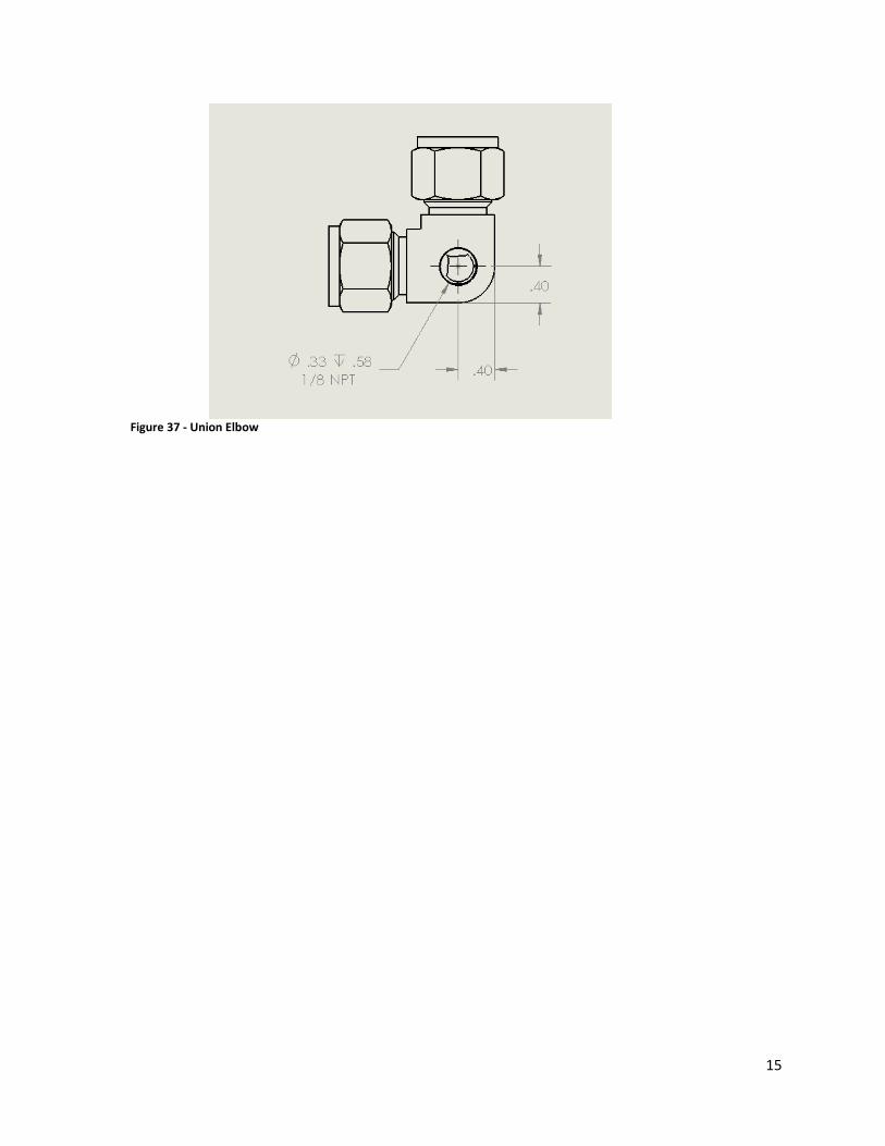
d. Union Elbow: i. A 1/8” NPT female hole must be drilled with a drill bit of size “Q” (0.332”) to
depth of .58” and tapped with a 1/8”-27 pipe tap into the SS Swagelok tube fitting, Union Elbow.
15
Figure 37 - Union Elbow

16
Assemble Bottom Components
3. Fully insert ½” tubing into a union elbow connector and hand tighten union elbow nut. Check that holes in ½” tubing are aligned vertically and are tapped from bottom to top and union elbow is aligned horizontally with tapped hole facing vertical.
Figure 38 - Bottom Assembly Union Elbow and 1/2" ss rod
4. Fully insert the open end of the ½” tubing into another union elbow facing the same direction as the first. Hand tighten the nut of the Union elbow onto the ½” tube.
Figure 39 - Bottom Assembly
5. Check that the exposed distance of the ½” tubing between elbows is about 9.65” and that the holes are centered. If these values have been checked than hand tighten union elbow nuts and then tighten 1 and a quarter turns with wrenches. (Directions for tightening Swagelok pieces can be found in Appendix)
6. Continue fully inserting ½” tubing into Union Elbows, checking distances, and tightening to make
a square. NOTE: hand tighten nut on the union elbows then tighten a turn and a quarter with a
9.65”
2.325”
2.325”

17
wrench. (See Swagelok guide in Appendix.)
Figure 40 - Bottom Assembly
7. Place 304 Bar ¼” X ½”X 9” on top of ½” tubing and screw in 8-32 machine screws from bottom of tubing to attach. Do this for all four pieces of ½” tubing.
Figure 41 - Halfway through attaching 304 bars to tubing

18
8. Screw in SS Swagelok Tube Fitting, Male Connector, 3/8 in. Tube OD x 1/8 in. Male NPT to each
Union Elbow. Tighten connector fully.
9.
10. Attach powder coated stainless steel bars by screwing in 6-32 machine screws from top.
Figure 43 - Bottom Assembly Solidworks Figure 42 - Bottom assembly of Swagelok 1/8" NPT connector on model
Figure 44 - Bottom Assembly Solidworks Figure 45 - Bottom Assembly model

19
Top of Camera Cage
Gather Materials
1. Gather materials from the bill of materials listed under Top components or alternate components of same size and material from a different vendor.
Camera Cage Top Components White Delrin ® Acetal
Resin Sheet, 3/4" Thick, 12" x 12" ( If using this sheet the model will be slightly
smaller than the 14”x14” first model
therefore all dimensions presented
would need to be resized – See
material below)
Figure 46 - McMaster Carr
McMaster Carr Reference number: 8573K21
$67.67 1 or 0 1 sheet 12”X
12”
White Delrin ® Acetal Resin Sheet, 3/4"
Thick, 24" x 24"(See above material)
Figure 10 – McMaster Carr
McMaster Carr Reference number: 8573K81
$217.50 1 or 0 Machine to 1
sheet 14”x14”
Type 304 Stainless STL Threaded Pipe Fitting 1/4 Pipe Size, Hex Head Plug, 150
PSI Figure 47 - McMaster Carr
McMaster Carr Reference number: 4464K252
$2.00 4 4
Corrosion-Resistant Eyebolt for Lifting
W/Shoulder, 316SS, 1/4"-20 Thrd Size, 1"
Lg Thrd
Figure 48 - McMaster Carr
McMaster Carr Reference number: 8891T72
$11.28 4 4
Type 18-8 Stainless Steel Hex Nut, 1/4"-20 Thread Size, 7/16" Wide, 7/32" High (Pack of 100)
Figure 49 - McMaster Carr
McMaster Carr Reference number:
91845A029
$4.64 1 6
Multipurpose Type 304 Stainless Steel 90 Degree Angle,
1/4" Thick, 3" x 4" Leg Lengths 6”
Figure 50 - McMaster Carr
McMaster Carr Reference number: 1260T56
$36.49 1 1, 2.5” X 3.5” X 3.5” (could
be larger)

20
18-8 Stainless Steel Hex Head Cap Screw
1/4"-20 Thread, 1" Long, Fully Threaded,
Packs of 50
Figure 51 - McMaster Carr
McMaster Carr Reference number:
92240A542
$6.93 1 2
18-8 Stainless Steel Hex Head Cap Screw
1/4"-20 Thread, 3-1/2" Long, Packs of
10 Figure 52 - McMaster Carr
McMaster Carr Reference number:
92198A556
$4.06 1 2
Go Pro Mount Quick Release Mount
Figure 53 - Go Pro Quick Release Mount
http://shop.gopro.com/mounts/curved-plus-flat-adhesive-
mounts/AACFT-
001.html#/start=1
$19.99 1 1
Camera Mount
Included in Camera Package
- 1 1
Stainless Steel Bracket (handle)
Custom made - 1 1

21
Machine Parts to Specifications
2. Once all Components are gathered they must be cut and custom machined to the specifications provided in the following steps (All dimensions in inches):
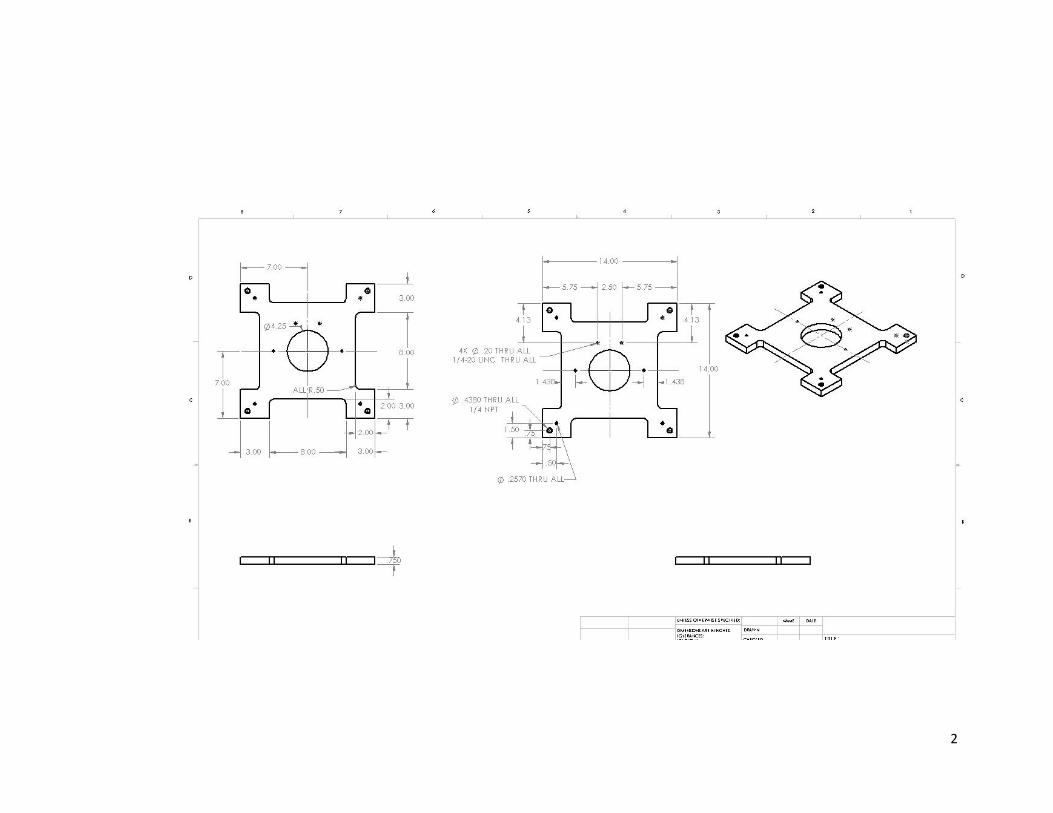
a. Delrin Plate: i. Secure Delrin plate to table and use drill press to drill a 4.25” hole in the center.
ii. Use a machine to cut 8”x2” blocks on each side of the plate.
Figure 54 - Working Drawing of Delrin plate
iii. Secure plate with top side facing up and drill the two small holes in near
center with a #7 bit and tap with a ¼”-20 from top to bottom.
Figure 55 - Working Drawing of Delrin plate

22
iv. Secure plate top side up and drill the holes on any corner. The larger hole is for a ¼”NPT and should be drilled and the smaller hole is a clearance hole for a 1/4” close fit eyebolt and should be drilled with an F drill bit (.2570”). The ¼” NPT should be tapped using a ¼” NPT tap from the top to a depth of .17” (For ¼” NPT plug) and from the bottom to a depth of .59” (For ¼” NPT Swagelok piece).
Figure 56 - One corner of Delrin plate
v. Repeat step 4 for all four corners of the delrin plate. vi. Add two holes in Delrin plate for the stainless steel bracket (Handle, part 19).
These holes will be dimensioned based on the metal bracket used. Make sure that the metal bracket is large enough to clear over the underwater camera itself.
b. 304 Stainless Steel 90 degree angle plate: i. Use a machine cut holes in 304 stainless steel plate according to the following
diagram.
Figure 57 - 90 degree plate working drawing
23
Assemble Top Components
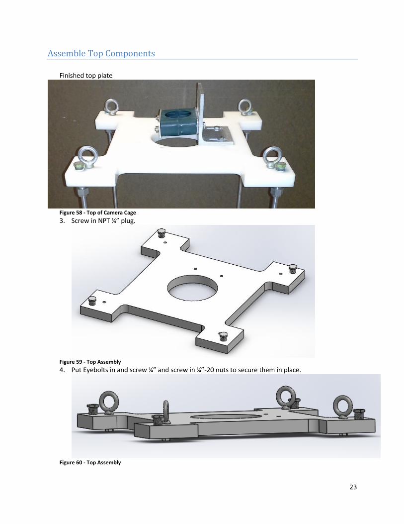
Finished top plate
Figure 58 - Top of Camera Cage
3. Screw in NPT ¼” plug.
Figure 59 - Top Assembly
4. Put Eyebolts in and screw ¼” and screw in ¼”-20 nuts to secure them in place.
Figure 60 - Top Assembly

24
5. Align 90 degree angle plate and screw ¼”-20 bolts to secure it.
Figure 61 - Top Assembly
6. Attach camera mount with ¼”-20 screws and nuts to 90 degree angle plate.
Figure 62 - Top Assembly

25
7. Screw in SS Swagelok Tube Fitting, Male Connector, 3/8 in. Tube OD x 1/4 in. Male NPT from
camera cage middle components to the underside of the delrin plate.
Figure 63 - Top Assembly 8. Attach Metal Handle (Part 19, stainless steel bracket) to the Delrin plate using two screws (part
15, ¼”-20).
Figure 64 - Top of Delrin plate with metal handle attached
26
Combine middle and top
Gather Components
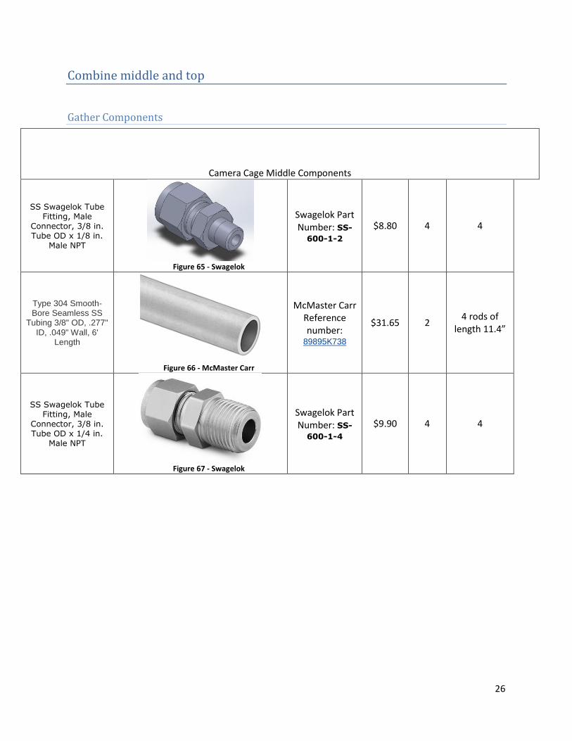
Camera Cage Middle Components
SS Swagelok Tube Fitting, Male
Connector, 3/8 in. Tube OD x 1/8 in.
Male NPT
Figure 65 - Swagelok
Swagelok Part Number: SS-600-1-2
$8.80 4 4
Type 304 Smooth-Bore Seamless SS
Tubing 3/8" OD, .277" ID, .049" Wall, 6'
Length
Figure 66 - McMaster Carr
McMaster Carr Reference number:
89895K738
$31.65 2 4 rods of
length 11.4”
SS Swagelok Tube Fitting, Male
Connector, 3/8 in. Tube OD x 1/4 in.
Male NPT
Figure 67 - Swagelok
Swagelok Part Number: SS-600-1-4
$9.90 4 4

27
Assembling Top and Bottom
1. Fully insert type 304 3/8” tubing into bottom sub assembly male connector 3/8” tube to 1/8” Male NPT and hand tighten connection. Do this for all 4 male connectors.
Figure 68 - Bottom Assembly
2. Fully insert top connections to tops of 3/8” stainless steel tubing.
Figure 70 - Cage Fully Assembled in Solidworks
3. Make sure all 8 3/8” male connectors are hand tightened and then tighten with a
wrench for 1 and a quarter turns.
Figure 69- Cage Fully Assembled

28
Cage Carrying Assembly
Gather Materials
Cage Carrying Components
19
Type 316 SS High-Strength Anchor
Shackle with Screw Pin, 7/16" Diameter, 2000# Work Load
Limit
Figure 71 - McMaster Carr
McMaster Carr Reference number: 3583T83
$19.21 5 5
20
Stainless Steel Load-Rated Wire Rope Lanyard Coated,
Loop/Loop, 1/8" Rope Diameter, 1' Length
Figure 72 - McMaster Carr
McMaster Carr
Reference number:
30745T436
$21.78 4 4
21
Stainless Steel Load-Rated Wire Rope Lanyard Coated,
Loop/Loop, 1/8" Rope Diameter, 3' Length
Figure 73 - McMaster Carr
McMaster Carr
Reference number:
30745T436
$29.72 1 1
22
Double Loop Cable-Support Grip
Corrosion Resistant, Midcable, 0.5"-0.61"
Cable Dia
Figure 74 - McMaster Carr
McMaster Carr
Reference Number: 70095K71
$54.51 1 1

29
Assembly
1. Attach a shackle and a metal lanyard to each eyebolt. And make sure the shackle is moused with a mousing wire or nylon ziptie. In this case there will be a lot of movement so it is beneficial to use a metal wire. (Mousing is tieing a wire around the shackle and through the eye of the threaded pin, so that the pin will not come unscrewed during motion.)
2. Attach all metal lanyards together with another shackle and also attach a 3” metal lanyard to
this connection as well.
Figure 77 - All metal lanyards and shackles are attached
Figure 76 -Example of a moused shackle (www.wikipedia.com
Figure 75 - Example of shackle and metal lanyard attached to eyebolt

30
3. Check that all shackles are “moused” (see step 1) 4. Attach the cable sock to the end of the central metal lanyard (longest metal lanyard).
Figure 78 -mid cable grip attached to central metal lanyard to reduce tension of electrical cables
a. In order to attach cable grip to the middle of the cable wire the cable is placed inside the cable grip where it will be attached.
TO Camera
TO Console
Wire used
to Weave
Glue/adhere wire
to cable grip & start
weave here
Figure 79 - mid-cable grip

31
b. The cable is aligned so that the cable closest to the shackle goes to the camera. The cable leaving the other end of the cable grip goes to the computer connection (console). It is required to adhere the cable to the end of the cable grip. This can be done with marine glue, marine tape, or both.
c. Once the cable is glued to the end of the cable grip then use the extra wire attached to weave starting at the spot glued through the entire grip like a shoe lace. At the end secure the ends of the wire weave.

32
Appendix
Figure 80 - From www.swagelok.com. Swagelok Manual


1
2

3
4

5