Power Cage
27
2867.6-091018 IMPORTANT: Read all instructions carefully before using this product. Retain this owner ’s manual for future reference. The specifications of this product may vary from this photo and, subject to change without notice. Power Cage
Transcript of Power Cage

2867.6-091018
IMPORTANT: Read all instructions carefully before using this product.
Retain this owner’s manual for future reference. The specifications of this
product may vary from this photo and, subject to change without notice.
Power Cage

PLEASE DO NOT RETURN THIS PRODUCT TO THE STORE.
STOP. Contact customer service if you have any questions
regarding assembly or proper operation of the machine.
Email us at: [email protected]
Or call us at: 1-844-641-7920
Hours:
8:00 am to 5:00 pm (PST)
Monday thru Friday

SERVICE-------------------------------------------------------------------- 2
LABEL PLACEMENT----------------------------------------------------- 3
PRODUCT SAFETY------------------------------------------------------ 4
ASSEMBLY PREPARATION-------------------------------------------- 5
PRODUCT DRAWING---------------------------------------------------- 6
OVERVIEW DRAWING-------------------------------------------------- 8
HARDWARE PACK-------------------------------------------------------- 10
PART LIST------------------------------------------------------------------- 11
STEP 1----------------------------------------------------------------------- 12
STEP 2----------------------------------------------------------------------- 14
STEP 3----------------------------------------------------------------------- 16
STEP 4----------------------------------------------------------------------- 18
STEP 5----------------------------------------------------------------------- 20
ADJUSTMENTS------------------------------------------------------------- 22
WARRANTY----------------------------------------------------------------- 24
PARTS REQUEST FORM---------------------------------------------- 25
TABLE OF CONTENTS
1

IMPORTANT: FOR NORTH AMERICA ONLY
For damaged or defective product, questions, replacement parts or any other service support, please
contact our customer service department by the below methods:
For The Best Service, please Email: [email protected] Response Time: 1-2 Business Days
Emailing us with the information above will be the best method to receive a response during peak business
hours
Website: www.paradigmhw.com
Toll-Free:
1-844-641-7920
(8:00 AM - 5:00 PM Pacific Standard Time, Monday thru Friday)
Response time may vary via calling
Please have the following information ready when requesting for service:
Your name
Phone number
Model number
Serial number
Part number
Proof of Purchase
For damaged or defective product please contact our customer service before returning to the store.
Paradigm Health & Wellness, Inc.
1189 Jellick Ave.
City of Industry, CA 91748, USA
SERVICE
2

LABEL PLACEMENT
3

WARNING: Before using this equipment you should consult with your personal physician to
see if the Power Cage is appropriate for you. Do not use this equipment without your
physician’s approval. Do not use this equipment if you have any of the following conditions
or ailments:
Extreme obesity
Glaucoma, retinal detachment or conjunctivitis
Pregnancy
Spinal injury, Cerebral Sclerosis, or acutely swollen joints
Middle ear infection
High blood pressure, Hypertension, Recent stroke or Transient ischemic attack
Heart or circulatory disorders for which you are being treated
Hiatus hernia or Ventral hernia
Bone weaknesses including Osteoporosis, Unhealed fractures, Modularly pins, or Surgically
implanted orthopedic supports
Use of anti-coagulants including Aspirin in high doses
The Maximum Weight Capacity for this product is 1500lbs/680kgs.
Read all instructions carefully before assembling and operating this product. Retain this
owner’s manual, do not remove any safety labels from the machine and keep the original
purchase receipt for future reference.
This Power Cage was designed and built for optimum safety. However, certain precautions apply
whenever you use the exercise equipment. Be sure to read the entire manual before assembling
and operating this equipment. Also, please note the following safety instructions:
1. Consult your physician or other health care professionals before using the piece of equipment.
2. Always wear proper exercise apparel when using the equipment. Use care when getting on or
off the unit.
3. If at any time you feel faint, light-headed, or dizziness while operating this equipment, stop
exercising immediately and contact your physician. You should also stop exercising if you
are experiencing pain or any kind of discomfort.
4. Keep children and pets away from the equipment at all times.
5. Only one person should use the equipment at a time.
6. Make sure your equipment is correctly assembled before you use it. Be sure all screws, nuts,
and bolts are tightened prior to use. Check screws, nuts, and bolts are tight on a weekly basis.
7. Do not operate this or any exercise equipment if it is damaged.
8. Wait 2 hours after eating before using the exercise equipment. If you get nauseous, stop
exercising as soon as you feel queasy.
9. This product should be placed on a flat surface when using. A mat or other covering material
on the ground is recommended. For indoor use only, do not use outdoors or near water.
10. Keep hands and feet away from any moving parts. Do not insert any object into any
openings on the equipment.
11. Keep loose clothes, jewelry, limbs and long hair away from moving parts.
12. Children under the age of 12 should not use this fitness equipment.
13. Children from 12 to 18 should have adult supervision.
14. WARNING: CANCER AND REPRODUCTIVE HARM--WWW.P65WARNINGS.CA.GOV.
4
PRODUCT SAFETY
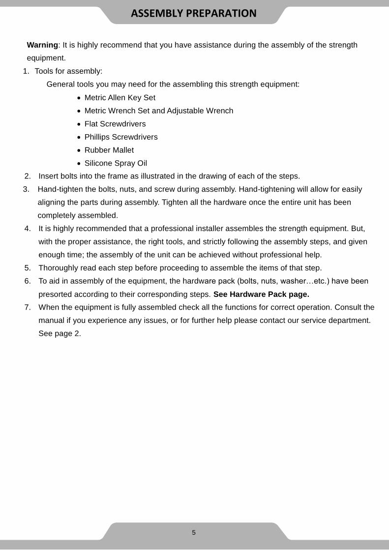
Warning: It is highly recommend that you have assistance during the assembly of the strength
equipment.
1. Tools for assembly:
General tools you may need for the assembling this strength equipment:
Metric Allen Key Set
Metric Wrench Set and Adjustable Wrench
Flat Screwdrivers
Phillips Screwdrivers
Rubber Mallet
Silicone Spray Oil
2. Insert bolts into the frame as illustrated in the drawing of each of the steps.
3. Hand-tighten the bolts, nuts, and screw during assembly. Hand-tightening will allow for easily
aligning the parts during assembly. Tighten all the hardware once the entire unit has been
completely assembled.
4. It is highly recommended that a professional installer assembles the strength equipment. But,
with the proper assistance, the right tools, and strictly following the assembly steps, and given
enough time; the assembly of the unit can be achieved without professional help.
5. Thoroughly read each step before proceeding to assemble the items of that step.
6. To aid in assembly of the equipment, the hardware pack (bolts, nuts, washer…etc.) have been
presorted according to their corresponding steps. See Hardware Pack page.
7. When the equipment is fully assembled check all the functions for correct operation. Consult the
manual if you experience any issues, or for further help please contact our service department.
See page 2.
ASSEMBLY PREPARATION
5

PRODUCT DRAWING
6

7
This page was intentionally left blank

OVERVIEW DRAWING
8
487
487
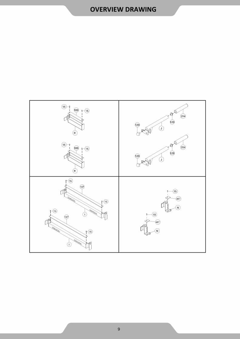
OVERVIEW DRAWING
9

HARDWARE PACK
10

Part# Description Qty. Part# Description Qty.
A Base Beam 2 15 SCREW M6x10L 10
B Vertical Post 4 16 Hex Bolt M12x1.75x105L 12
C Upper Beam 2 17 Hex Bolt M12x1.75x85L 4
D Front Crossbeam 1 52 Washer
D13xD24x2.5 66
E Wide Grip Bar 1 55 Spring Washer
D20xD12.2x3.2 8
F Close Grip Bar 2 76 Nylon Nut M12 28
G Rear Crossbeam 1 78 Cap Nut M12 4
H Bar Bell Catch 2 128 Flat End Cap D50xt2.0 2
I Safety Catch 2 129 Domed End Cap D50xt2.0 2
J Dip Bar 2 130 Flat End Cap D76xt2.0 8
K Stability Beam 1 187 Safety Catch Bumper
890x50xt5.0 2
L Mounting Plate 10 188 Safety Catch Bumper
285x50xt5.0 2
M Stability Plate 1 189 Foot Pad 100x80xt5.0 4
N J-Hook 2 204 Handgrip Φ49xΦ55x250 2
7 Hex Bolt M12x1.75x80L 16 487 Rubber Pad 62x45xt8.0 2
8 Hex Bolt M12x1.75x100L 2
PART LIST
11

1A. Attach Stability Plate (M) to the two Base Beams (A) by using:
2 - (8) Hex Head Bolt M12x1.75x100L
4 - (52) Washer D13xD24x2.5
2 - (76) Nylon Nut M12
Thoroughly tighten the hardware once complete.
STEP 1
12

8
STEP 1
13
Wrench 2PCS
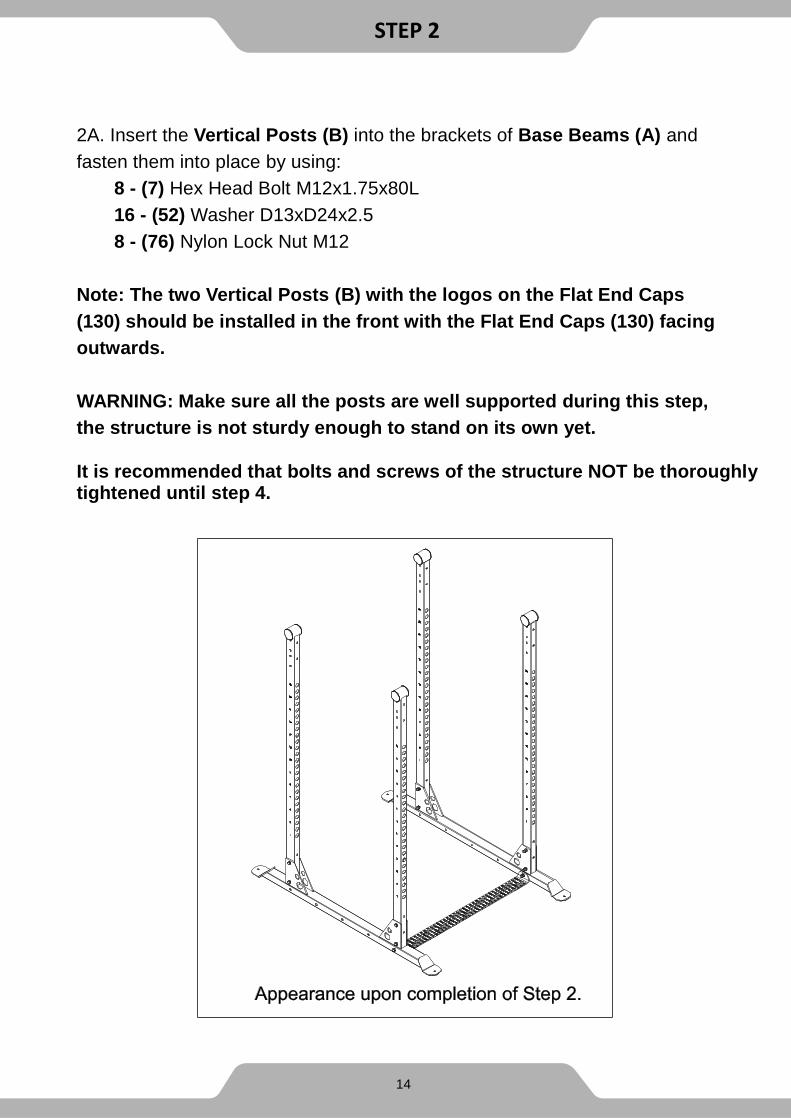
2A. Insert the Vertical Posts (B) into the brackets of Base Beams (A) and
fasten them into place by using:
8 - (7) Hex Head Bolt M12x1.75x80L
16 - (52) Washer D13xD24x2.5
8 - (76) Nylon Lock Nut M12
Note: The two Vertical Posts (B) with the logos on the Flat End Caps
(130) should be installed in the front with the Flat End Caps (130) facing
outwards.
WARNING: Make sure all the posts are well supported during this step,
the structure is not sturdy enough to stand on its own yet.
It is recommended that bolts and screws of the structure NOT be thoroughly tightened until step 4.
STEP 2
14

STEP 2
15
Wrench 2PCS

3A. Attach the Rear Crossbeam (G) and the two Mounting Plates (L) to the
two rear Vertical Posts (B) at the location of the matching by using:
4 - (7) Hex Head Bolt M12x1.75x80L
8 - (52) Washer D13xD24x2.5
4 - (76) Nylon Nut M12
Note: The Rear Crossbeam (G) should be installed with the logo facing
forward.
3B. Attach the Upper Beam (C) and two Mounting Plates (L) to the side
Vertical Posts (B) at the location of the matching by using:
4 - (16) Hex Head Bolt M12x1.75x105L
8 - (52) Washer D13xD24x2.5
4 - (76) Nylon Nut M12
3C. Attach the Upper Beams (B) and two Mounting Plates (L) to the side
Vertical Posts (B) at the location of the matching by using:
4 - (16) Hex Head Bolt M12x1.75x105L
8 - (52) Washer D13xD24x2.5
4 - (76) Nylon Nut M12
It is recommended that bolts and screws of the structure NOT be thoroughly tightened until step 4.
STEP 3
16

STEP 3
17
Wrench 2PCS

4A. Attach the Front Crossbeam (D) and the two Mounting Plates (L) to the
two front Vertical Posts (B) at the location of the matching by using:
4 - (7) Hex Head Bolt M12x1.75x80L
6 - (52) Washer D13xD24x2.5
2 - (76) Nylon Nut M12
Note: The Front Crossbeam (D) can be installed at a height of 83” inches, or 86” inches depending on which set of holes are used at the top of the Vertical Posts (B).
4B. Mount the Close Grip Bars (F) and Wide Grip Bar (E) to the Front
Crossbeam (D) by using:
4 - (17) Hex Head Bolt M12x1.75x85L
4 - (55) Spring Washer D20xD12x3.2
8 - (52) Washer D13xD24x2.5
4 - (78) Cap Nut M12
Thoroughly tighten the hardware once complete.
18
STEP 4

STEP 4
19
Wrench 2PCS

5A. Attach the Stability Beam (K) and the two Mounting Plates (L) to the
two rear Vertical Posts (B) by using:
4 - (16) Hex Head Bolt M12x1.75x105L
8 - (52) Washer D13xD24x2.5
4 - (76) Nylon Nut M12
Now that the cage is fully assembled, proceed with thoroughly tightening all the hardware.
STEP 5
20
The sticker should be facing Upwards when installing the Stability Beam (K)
to the two rear Vertical Posts (B). With the two sets of bolt holes closest to
the ground.

STEP 5
21
Wrench 2PCS

A. The two Bar Bell Catches (H) can be inserted into any of the holes along
the Vertical Posts (B). Place them on opposite sides of the cage and at a
comfortable height that will assist you during your workout.
B. The two Safety Catches (I) can be inserted into any of the holes along the
Vertical Posts (B). Place them at a height that will help keep you safe during
your workout.
C. The two Dip Bars (J) can be inserted on to either of the Safety Catches (I)
Parts. Install the two Dip Bars (J) at a comfortable distance from each other
to allow enough space for preforming dips.
D. The two J-Hooks (N) can be inserted into any of the holes along the
Vertical Posts (B). Place them at a comfortable position for the desired
workout.
The Vertical Posts (B) are numbered along their length to aid in placing
the two Safety Catches (I) at equal heights on the four Vertical Posts (B).
WARNING: We recommend placing the Safety Catches (I) in an
orientation that allows the Dip Bars (J) to be on the inside of the cage
while performing dips.
ADJUSTMENTS
22

N
N
ADJUSTMENT
23

MANUFACTURER’S LIMITED WARRANTY
Paradigm Health & Wellness guarantees to the original purchaser that this product is free from defects in material and workmanship when used for the purpose intended, under the conditions that it has been installed and operated in accordance with Paradigm’s Owner’s Manual. Paradigm’s obligation under this warranty applies to the following:
COMPONENT LENGTH OF WARRANTY
Structural Frame 10 Years For Home Use Only
Parts 3 Years For Home Use Only
Wearable Parts 2 Years For Home Use Only
Exclusions from Warranty Coverage:
Paradigm does not warrant against and is not responsible for, and no implied warranty shall be
deemed to cover, any product failure, product malfunction, or damages attributable to:
1. Improper installation and/or failure to abide by Paradigm’s installation guidelines;
2. Use of this product beyond normal home use, or in an application for which it was not designed.
3. All exchanged parts and Products replaced under this limited warranty will become the property
of Paradigm Health and Wellness.
4. Damage caused by vandalism, accidents, inadequate maintenance, or by animals.
5. Any act of Nature (such as fire, flooding, snow, ice, hurricane, earthquake, lightning or other
natural disaster), environmental condition (such as air pollution, mold, mildew, etc.), or staining
from foreign substances (such as dirt, grease, oil, etc.).
6. Normal weathering due to exposure to sunlight, weather and atmosphere which can cause
colored surfaces to, among other things, flake, rust, accumulate dirt or stains.
7. Improper operation, alteration, handling, storage, abuse or neglect of the product.
Paradigm, using its sole discretion, will either repair or replace free of charge any part(s)
proven to be defective under normal home use. Any repair or replacement shall provide no
new warranty coverage, but shall retain only the remaining portion of the original product’s
warranty. This warranty is offered only to the original purchaser and is not transferable.
Proof of original purchase is required.
Ordering Replacement Parts
Replacement parts can be ordered by emailing our customer service department:
Open Monday thru Friday 8:00 AM - 5:00 PM (PST).
When ordering replacement parts please have the following information ready:
1. Owner’s Manual
2. Model Number
3. Description of Parts
4. Part Number
5. Date of Purchase
24
WARRANTY

Paradigm Health & Wellness, Inc.
EMAIL THIS FORM WITH YOUR RECEIPT OF PURCHASE TO
NAME:______________________________________________________________________
ADDRESS:__________________________________________________________________
CITY:________________________ STATE:_____________ ZIP:________________________
TELEPHONE: (Day)_________________________________________________________
(Night)________________________________________________________
SERIAL#:____________________________________________________________________
MODEL#:____________________________________________________________________
PURCHASE DATE:____________________________________________________________
PLACE OF PURCHASE:________________________________________________________
“YOUR ORDER WILL BE PROCESSED WITHIN 3 BUSINESS DAYS”
*This form can also be faxed to #: 626-810-2166
PART # DESCRIPTION QTY
PARTS REQUEST FORM
25