Caltrans Geotechnical Manual Page 1 of 22 June 2013 Introduction
22
Caltrans Geotechnical Manual Page 1 of 22 June 2013 Introduction Rock cut slope design takes into account the structural characteristics and strength properties of the rock masses to develop designs that address constructability and long- term performance. Rock cut slope design is performed to evaluate existing and proposed rock cuts, and to determine the cut slope angle for the steepest continuous stable slope without intermediate slope benches. The design accounts for cut slope performance and safety while optimizing excavation quantities. Slope stabilization and rockfall protective measures may be required to minimize localized or small scale instabilities within the overall cut. Environmental requirements, right-of-way impacts, and other project goals may at times also warrant slope stabilization measures. The design also provides excavation characteristics (blasting, ripping) and earthwork factors for material disposal or reuse as fill material. Three publications frequently referenced in this section that are both recommended and readily available are “Rock Slopes” by Manfakh et. al. 1998 (40), “Rock Slope Engineering” by Wyllie and Mah 4 th Edition 2004 (51), and “Rock Slope Engineering” by Hoek and Bray 1980 (34). Although thorough engineering analysis should be performed, it is important to note that engineering analysis, in itself does not eliminate uncertainties in defining all of the controlling conditions presented within a given rock or soil mass. Sound engineering judgment and experience in cut slopes should be applied in the design. Experience, especially with similar rock and slopes, should carry considerable weight in determining the effectiveness of a cut slope design. Case histories in similar conditions should be consulted to provide additional guidance. Rock Cut Slope Design In addition to standard site reconnaissance and geotechnical investigation requirements, rock cut slope design relies heavily upon surface mapping, geomaterial identification, and discontinuity logging. Logging rock structure discontinuities (fracture/joint patterns) and their condition in boreholes and mapping them on surface outcrops is essential to rock cut slope design, as discontinuities strongly influence rock slope stability. Assessment of groundwater conditions in the rock discontinuities, as is true of any slope, is also critical to the assessment of stability (01, 28, 32, 49, and 40). “Rock Slopes” (40) presents a good overview of design in Chapter 1 on pages 1-1 to 1-3.
Transcript of Caltrans Geotechnical Manual Page 1 of 22 June 2013 Introduction

Caltrans Geotechnical Manual
Page 1 of 22 June 2013
Introduction
Rock cut slope design takes into account the structural characteristics and strength
properties of the rock masses to develop designs that address constructability and long-
term performance.
Rock cut slope design is performed to evaluate existing and proposed rock cuts, and to
determine the cut slope angle for the steepest continuous stable slope without
intermediate slope benches. The design accounts for cut slope performance and safety
while optimizing excavation quantities. Slope stabilization and rockfall protective
measures may be required to minimize localized or small scale instabilities within the
overall cut. Environmental requirements, right-of-way impacts, and other project goals
may at times also warrant slope stabilization measures. The design also provides
excavation characteristics (blasting, ripping) and earthwork factors for material disposal
or reuse as fill material. Three publications frequently referenced in this section that are
both recommended and readily available are “Rock Slopes” by Manfakh et. al. 1998 (40),
“Rock Slope Engineering” by Wyllie and Mah 4th
Edition 2004 (51), and “Rock Slope
Engineering” by Hoek and Bray 1980 (34).
Although thorough engineering analysis should be performed, it is important to note that
engineering analysis, in itself does not eliminate uncertainties in defining all of the
controlling conditions presented within a given rock or soil mass. Sound engineering
judgment and experience in cut slopes should be applied in the design. Experience,
especially with similar rock and slopes, should carry considerable weight in determining
the effectiveness of a cut slope design. Case histories in similar conditions should be
consulted to provide additional guidance.
Rock Cut Slope Design
In addition to standard site reconnaissance and geotechnical investigation requirements,
rock cut slope design relies heavily upon surface mapping, geomaterial identification, and
discontinuity logging. Logging rock structure discontinuities (fracture/joint patterns) and
their condition in boreholes and mapping them on surface outcrops is essential to rock cut
slope design, as discontinuities strongly influence rock slope stability. Assessment of
groundwater conditions in the rock discontinuities, as is true of any slope, is also critical
to the assessment of stability (01, 28, 32, 49, and 40). “Rock Slopes” (40) presents a good
overview of design in Chapter 1 on pages 1-1 to 1-3.

Caltrans Geotechnical Manual
Page 2 of 22 June 2013
Context Sensitive Considerations for Rock Slopes
Context sensitive designs in transportation are key to developing facilities that fit within
the engineered setting, preserving scenic, aesthetic, historic, and environmental resources
while maintaining motorist safety and mobility. Developing context sensitive solutions
for rock slope design and rockfall mitigation is a stepwise process that should involve all
stakeholders early in the scoping and design process. Excavation and mitigation design
should take into account the area’s scenic concerns, historical significance, and wildlife
corridors, as well as the safety, cost, and capacity of its roadways. Design specifications
should allow the project staff flexibility to modify the slope geometry and engineer
mitigation method(s) that fit regional characteristics, roadway theme, and geological
features. Context sensitive projects require frequent communication between the
contractor and the project owner to ensure the final product meets all stakeholders’
interests (01).
Site Investigation
Assessment of slope stability requires observation of the site in the field. This can only be
accomplished by hiking around, or in some cases accessing the site using ropes. The area
must be studied both locally and regionally. A proper investigation consists of a literature
search, review of historic and current geologic maps, aerial photo review and a thorough
field investigation which must include a surface and may include a subsurface
investigation(s).
Literature Search
Knowledge of the geology of the area is critical and can be obtained by examining
published geologic maps and reports along with available aerial photographs.
Maintenance records and interviews with personnel familiar with the site should be
obtained wherever and whenever possible. The maintenance history, including a
description of past problems and interim mitigation measures should be obtained. Where
there are existing cut slopes obtain the “As-Builts” from the district office and the file of
record, in the Geotechnical/District library, for any geotechnical investigations
performed.
Field Mapping
For widening projects with existing cuts, reviewing the performance of existing slopes
(both cuts and natural) in the area or region must be performed. For new alignments, field
observations of naturally formed cuts in drainages or along the ocean and cuts outside the
State R/W can provide valuable information where cuts are proposed in previously
undisturbed areas.

Caltrans Geotechnical Manual
Page 3 of 22 June 2013
The areas must always be mapped in detail on both the local and regional level. Geologic
maps on a wide variety of scales are available from the USGS, CGS, local county and
government entities and private organizations. The Caltrans Landslide Technical Team is
adopting a mapping method for identifying instabilities and should be used in the
mapping process (07, 08, 34, 39, 40, and 51). “Rock Slopes” (40) presents a good
overview of planning an investigation program in Chapter 2 and in Appendix 2.
In addition typical observations collected during the field investigation are:
• Slope length (both horizontal and vertical): physically measure with tape, range
finder, or pace.
• Slope Ratio: physically measure with Clinometer, Brunton or Clar Compass.
• Slope surface: smooth, planar, undulatory, and blocky; if undulatory or blocky,
note the difference in height from the ‘peaks’ to the ‘valleys’.
• Describe lithology of the soil and/or rock.
• Estimate or physically measure native slope ratios above and below cuts, as well
as on nearby slopes of similar geology. Note presence of boulders, including
average size, maximum size, shape, and rock type, as well as their location (top of
slope, on slope (embedded or loose), at base of slope).
• Local Stability - Note erosion features, rockfalls, slumps, rills, washes etc.
• Global Stability - Note presence of landslides and rockslides.
• Note moisture features, such as seeps, springs, wet areas, and their likely causes.
• Assess condition of existing slopes.
• Describe vegetation.
Where applicable rock structure data should be collected and recorded. In addition to
basic field observations a scan line analysis should be performed on open cut slopes or
natural slopes. This information can be used in estimating the Rock Mass Quality (Q)
and/ the Geological Strength Index (GSI). An organized table should be developed which
includes the following information of the nature of the rock discontinuities. “Rock
Slopes” (40) presents a thorough description of the following geological terms in Chapter
2, Section 2.3.
• Location
• Station
• Dip/Dip Direction
• Type of Discontinuity (bedding, jointing, fractures, faulting, etc.)
• Persistence
• Spacing
• Filling
• Asperities
• Roughness

Caltrans Geotechnical Manual
Page 4 of 22 June 2013
• Rock Quality Designation (RQD)
• Discontinuity Sets
• Discontinuity Roughness
• Discontinuity Alteration
• Discontinuity Presence of water
• Weakness Zones intersecting the excavation
Existing Roadway Conditions
• Number of lanes.
• Lane width.
• Paved shoulder width and unpaved shoulder width, and slope ratio of both.
• Catchment Area (width of roadway between the base of the slope and the edge of
traveled way available for rock and debris containment) and back slope ratio.
• Observations of pavement condition, presence and location of cracking,
settlement, patching. Make educated guess as to why pavement is in the condition
it is in.
Existing man-made structures
• Walls, foundations, building types, culverts, under-crossing, utilities etc.
• Note general conditions of each structure.
• Note if roadway work might impact the structure.
Provide notes on additional geologic investigations that may need to be performed to
adequately characterize the site, ie: additional boring locations, geophysical studies, etc.
• Field drawings
o Develop a scaled field drawing of the area of concern.
o Develop one or more typical cross sections of the area of concern.
o Develop cross section with initial mitigation approach if appropriate.
• Photographs of area of concern
o Photos of problem area (direct/overall).
o Photos of main features or any other important feature inside or outside of
the area.
Subsurface Investigations
Determining the nature of the subsurface material provides valuable information for cut
slope design. Two methods to obtain subsurface data which are readily available are
drilling subsurface borings both vertically and horizontally and performing geophysical
studies. Please also refer to the “Caltrans Soil and Rock Logging” manual (13) and
reference (23).
Caltrans Geotechnical Manual
Page 5 of 22 June 2013
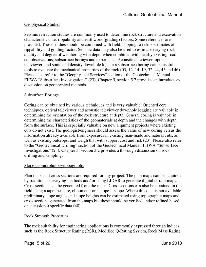
Geophysical Studies
Seismic refraction studies are commonly used to determine rock structure and excavation
characteristics, i.e. rippability and earthwork (grading) factors. Some references are
provided. These studies should be combined with field mapping to refine estimates of
rippability and grading factor. Seismic data may also be used to estimate varying rock
quality and degree of weathering with depth when combined with nearby existing road
cut observations, subsurface borings and experience. Acoustic televiewer, optical
televiewer, and sonic and density downhole logs in a subsurface boring can be useful
tools to evaluate the mechanical properties of the rock (03, 12, 14, 19, 32, 44, 45 and 46).
Please also refer to the “Geophysical Services” section of the Geotechnical Manual.
FHWA “Subsurface Investigations” (23), Chapter 5, section 5.7 provides an introductory
discussion on geophysical methods.
Subsurface Borings
Coring can be obtained by various techniques and is very valuable. Oriented core
techniques, optical televiewer and acoustic televiewer downhole logging are valuable in
determining the orientation of the rock structure at depth. General coring is valuable in
determining the characteristics of the geomaterials at depth and the changes with depth
from the surface. This is especially valuable on new alignment projects where existing
cuts do not exist. The geologist/engineer should assess the value of new coring versus the
information already available from exposures in existing man-made and natural cuts, as
well as existing outcrops, and weigh that with support cost and risk (23). Please also refer
to the “Geotechnical Drilling” section of the Geotechnical Manual. FHWA “Subsurface
Investigations” (23), Chapter 3, section 3.2 provides a thorough discussion on rock
drilling and sampling.
Slope geomorphology/topography
Plan maps and cross sections are required for any project. The plan maps can be acquired
by traditional surveying methods and/ or using LIDAR to generate digital terrain maps.
Cross sections can be generated from the maps. Cross sections can also be obtained in the
field using a tape measure, clinometer or a slope-a-scope. Where this data is not available
preliminary slope angles and slope heights can be estimated using topographic maps and
cross sections generated from the maps but these should be verified and/or refined based
on site (slope) specific data (40).
Rock Strength Properties
The rock suitability for engineering applications is commonly expressed through indices
such as the Rock Structure Rating (RSR), Modified Q-Rating System, Rock Mass Rating

Caltrans Geotechnical Manual
Page 6 of 22 June 2013
System (RMR), Unified Rock Classification System (URCS) and the Slope Rock Mass
Rating System (SMS). Strength parameters can also be estimated from empirical methods
(09, 35, and 49). Please also refer to the “Geotechnical Laboratory Testing” Section.
FHWA “Subsurface Investigations” (23), Chapter 8 provides an introduction to
laboratory testing for rocks.
Rock Identification/ Rock Classification, (13, 21, 24 and 30).
• Igneous
• Metamorphic
• Sedimentary
• Transitional Materials
Rock Durability
Rock characteristics that affect long-term stability of the slope such as the degree of
weathering, potential for weathering (physical, chemical), hardness, erodibility, and slake
durability should be considered in the design. Durable rock is considered rock-like in
character and relatively unweathered and hard. Nondurable rocks are rock-like in
character in place but will weather during the proposed life of the cut to soil like
materials. The depth and degree of weathering is dependent on the original material and
weathering environment. Indices that might be used that can add to the rock durability
quantification are the LA rattler test, and the slake durability test. Moh’s hardness scale is
also easily applied and evaluated (04, 13, 24, 29, 30, 35, and 40).
Rock Structure
The presence and characteristics of discontinuities, such as joints, foliations, shears,
fractures, and faults are important factors in the stability of rock slopes. The orientation,
frequency, persistence, and shear strength of rock discontinuities are measured in the
field from existing cuts, rock core and/or outcrops. Projections of the dip and dip
direction of the measured discontinuities and discontinuity shear strength are typically
presented and evaluated on stereonets to determine if failure is kinematically possible.
Hoek and Bray’s “Rock Slope Engineering” (34) presents a good overview of the
relationship between discontinuities and rock slope stability in Chapter 2.
If outcrops do not occur within the project area they should be sought on nearby slopes
that are composed of the same formation. If nearby outcrops are not available, the “type
section” of the formation is the next most useful resource in determining the rock
structure.
When rock properties and discontinuities need to be investigated beyond their ground
surface expressions or when no outcrops are available, coring exploration is used to

Caltrans Geotechnical Manual
Page 7 of 22 June 2013
obtain rock cores. Non-oriented cores provide information on the density, persistence,
roughness, and infilling of discontinuities. Oriented coring exploration or down hole
geophysics may be used to obtain information on the dip and dip direction of
discontinuities (10, 20, 30, 34 and 41).
Rock Shear Strength
The shear strength developed along potential rupture surfaces within a slope is an
important influence on the stability of rock slopes. The rock mass is the term used to
describe the material on the rupture surface. Rock mass strength (UCS) and shear
strength along discontinuities must be evaluated to determine potential for failures. If
field mapping indentifies adversely oriented rock structure it will be necessary to
determine the shear strength of the discontinuities (friction angle and cohesion). This
information can be obtained by laboratory testing or by reviewing published tables of
rock strength parameters. Testing is typically performed using a direct shear box
developed to accommodate rock core and similar sized rock samples. There are many
tables to empirically estimate rock strength parameters that are available in the
references. It is also important to determine the rock strength parameters of rock
durability and compressive strength. Durability is typically measured with a slake
durability test. This test is commonly used to establish weathering characteristics of the
rock mass. Compressive strength can be obtained from rock core by performing an
unconfined compressive strength test or a point load test on rock core or similarly sized
rock samples (07, 24, 34, 40, 51 and 52). “Rock Slopes” (40) presents a good overview of
rock strength properties throughout Chapter 3.
Hydrology
Groundwater and surface water conditions must be evaluated for the design and analysis
of rock cut slopes. Hydraulic pressure acting within the discontinuities can cause
significant destabilization by decreasing the shear strength due to uplift and/or increasing
the driving forces acting on the block. Typically, the groundwater level within a slope can
be estimated by observing seepages from and around the rock slope. When groundwater
conditions are unknown and groundwater is expected to influence the stability of the
slope, groundwater pressures can be measured using piezometers (34, 40 and 51). “Rock
Slopes” (40) presents a good overview of groundwater flow, permeability and pressure
throughout Chapter 4.

Caltrans Geotechnical Manual
Page 8 of 22 June 2013
Analysis
Slope Stability Analyses
The stability of hard rock slopes is typically controlled by discontinuities (joint and joint
sets) within the rock. Failures tend to occur as discrete blocks. Discontinuities form
intersecting planes of weakness. Without discontinuities, rock slopes, even some
composed of relatively weak rock could stand hundreds of feet tall without the potential
for failure. Kinematic analysis of the discontinuities is performed to determine the
potential modes of failure (wedge, planar, toppling, and circular). This is followed by a
static slope stability analyses to determine the factor of safety of potential failure modes.
The stability of highly weathered to decomposed rock slopes is often not controlled by
discontinuities, but rather by a Mohr-Coulomb failure mode (circular) more typical of
soil slopes. Limit equilibrium analysis utilizing the shear strength and cohesion of the
rock mass is performed to determine the most likely failure surfaces and the global
stability in terms of a factor of safety. Highly fractured rock slopes in which there is
likely no single or distinct discontinuity surface on which movement will occur should
also be analyzed in this fashion. These analyses require a value for φ (friction angle) and
c (cohesion), which can be determined with lab tests such as a direct shear test (shear
box) or by back analysis of similar slopes that have failed (25, 30, 33, 34, 37, 40 and 51).
“Rock Slopes” (40) is a recommended reference for its discussion of the mechanics of
rock slope stability (Chapter 1, Section 1.4) and plane (Chapter 5), wedge (Chapter 6),
circular (Chapter 7) and toppling (Chapter 7) instabilities.
Kinematic Stability Analyses
A kinematic (limit equilibrium analysis) analysis is the first step in evaluating rock slope
stability. Kinematics refers to the motion of bodies without reference to the forces that
cause them to move (30). This analysis establishes the possible failure modes of the
blocks that comprise the slope. The analysis determines if the orientations (dip and dip
direction) of the various discontinuities will interact with the cut slope orientation and
inclination to form discrete blocks with the potential to fail. Failure modes typically fall
within one of three categories: plane failure, wedge failure, or toppling failure. The
analysis involves a comparison of the orientations of the dominant discontinuity sets with
the orientation of the cut slope. Where discrete blocks are formed and where the failure
surfaces that bound these blocks dip out of the slope (daylight) at an angle steeper than
the shear strength along the discontinuity, failure is kinematically possible. A stereonet is
used to perform a discontinuity analysis where the discontinuities and slope data are
displayed. After the kinematic analyses have identified the most likely mode(s) of failure,
the next step is to perform a stability analysis using the shear strength of discontinuities
and groundwater conditions. The objective is to calculate the factor of safety of the slope
or individual block being analyzed. Limit equilibrium methods for evaluating slope

Caltrans Geotechnical Manual
Page 9 of 22 June 2013
stability analysis focus on the relative magnitude of the resisting and driving forces. Hoek
and Bray “Rock Slope Engineering” (34) presents a good overview of the stereonets, the
graphical presentation of the data and kinematic analysis in Chapter 3. More advanced
stereonet analyses are presented in Goodman (30) Appendix 5.
Discontinuity Analysis
Interpretation of the geological structure data requires the use of stereographic
projections onto stereonets that allow the 3- dimensional orientation of data to be
represented and analyzed 2-dimensionally. The most commonly used projections are the
equal area net and the polar net. An important limitation of stereographic projections is
that they consider only angular relationships between lines and planes, and do not
represent the position or size of the feature (30, 34, 41, and 40). Chapter 2 in “Rock Slope
Engineering” (51) presents a thorough review of a discontinuity and kinematic analysis.
Figure 2.18 on page 38 presents a good graphical presentation of the limits of possible
sliding for wedge, planar and toppling failures.
Numerical Analysis
Numerical models are computer programs that attempt to represent the mechanical
response of a rock mass subjected to a set of initial conditions (such as in-situ stresses
and water levels), boundary conditions, and induced conditions (such as slope
excavation) (51). A number of computer models exist; however, two models are
approved and commonly used by Caltrans: ROCKPACK and Slope-W. Both programs
have been successfully used in rock slope applications and are recommended (28, 33, 42
and 51).
Planar, wedge, and toppling failures are routinely modeled with ROCKPACK. Planar
failures are also often routinely modeled with SLOPEW. Circular failures commonly
occur in decomposed rock, closely fractured rock, or rock fills. The typical curved
surface of this type of failure is not controlled by discontinuities, but rather by the shear
strength, which is a function of friction angle (φ), cohesion (c), and effective stresses of
the rock mass. These slopes may be analyzed using circular failure surfaces similar to the
methods used to analyze soil slopes. Computer programs, such as SLOPEW are routinely
used for the analysis. Chapter 10 in “Rock Slope Engineering” (51) presents a thorough
review of numerical analysis.
Seismic Considerations
Earthquake shaking can result in failures of cut slopes. The common types of instabilities
prone to seismic-induced failure in rock cut slopes are rockfalls, rock slides and debris
avalanches. The standard procedure for evaluating the stability of a nonliquefiable slope

Caltrans Geotechnical Manual
Page 10 of 22 June 2013
is the pseudostatic analysis, where, while performing a limit equilibrium analysis, a
lateral force is applied to the center of gravity of a mass having a failure potential. The
selection of shear strength in slope stability analyses involving seismic loadings should
be based on short-term undrained shear strengths. The pseudostatic procedure does not
provide an estimate of potential seismic deformations. In many instances, the stability of
a slope during an earthquake may drop below a factor of safety of 1 for only a brief
period of time during the transient shaking. In this case, a pseudostatic analysis would
indicate an unacceptable factor of safety below 1, but the actual deformation of the slope
may be minimal and the overall performance acceptable. For this reason the effects of
seismic shaking are not regularly considered in rock cut slope design.
When critical facilities are impacted and an analysis including seismic shaking is required
one accepted method of estimating seismic deformations of non-liquefiable slopes is the
Newmark Sliding Block Analysis. This method uses the yield acceleration of a slide mass
and a seismic time history to estimate the permanent seismic deformation. This seismic
analysis of slopes, however, is not used on a routine basis (26, 27, 40 and 51). Chapter 6,
Section 6.5 in “Rock Slope Engineering” (51) presents a thorough review of the seismic
analysis of rock slopes.
Rebound/Relaxation
When a slope is first excavated or exposed, there is a period of initial response resulting
from the elastic rebound, relaxation and/or dilation of the rock mass due to changes in
stress induced by the excavation (51). Newly excavated slopes commonly experience
small local instabilities as the result of changes of the strain due to the removal of
overburden. This condition is not necessarily indicative of long term instability, but rather
local adjustment. Experience has shown this to occur within days or weeks or, in rare
instances, months after construction (22, 30, 37, 43 and 51). “Landslides Analysis and
Control” (42; p. 196-197), provides an overview of the loss of strength in the rock mass
over time and the impact of residual and induced stresses on stability. Another good
discussion can be found in “Rock Slope Engineering” (51) in Chapter 13, Section 13.2.
Convex and Concave Slopes
The radius of curvature can have an important effect on slope stability. In slopes that are
concave in plan the horizontal tangential stresses tend to be compressive. In slopes that
are convex in plan, the horizontal tangential stresses tend to be tensile. Rock is stronger
in compression than in tension (34, 37, 43 and 51). “Landslides Analysis and Control”
(42, p. 196), provides an overview of the effects of slope geometry on stability.

Caltrans Geotechnical Manual
Page 11 of 22 June 2013
Factor of Safety (FS)
Typical target design Factor of Safety (FS) values range from 1.3 to 1.5; however, based
on engineering judgment, values outside of this range may be appropriate, depending on
the circumstances.
The minimum FS to be used in stability analyses for a specific rock slope depends on
factors such as:
1. The degree of uncertainty in the stability analysis inputs; the most important being
the amount of intact rock, rock mass strength, discontinuity spacing, discontinuity
shear strength and groundwater conditions
2. The level of investigation and data collection
3. Costs of constructing the slope to be more stable
4. Costs, risks to the travelling public, risks to the roadway, and other consequences
should the slope fail
5. Whether the slope is temporary or permanent
Rock Slope/ Landscape Integration
A major component of context sensitive design is the final appearance of an engineered
slope: how the slope looks on its own as well as how it fits into the surrounding
landscape. To create the best and most natural-looking results, engineers and designers
typically use a combination of excavation techniques, and rock slope/landscape
integration, which uses physical and cosmetic alterations to modify the shape of a slope
and give it a more natural appearance by mimicking the surrounding topography. In some
cases, safety or cost concerns make it impossible to achieve a completely natural look.
However, in any case, the geo-professional and the contractor should strive to develop a
slope that is safe, looks natural, and satisfies the interests of all project stakeholders.
Factors to consider are slope warping, slope rounding, drainage, catchment ditches, slope
angle, slope sculpting, and rock staining (01).
Design
Rock slope design consists of determining (1) the orientation of the cut, (2) the
inclination of the cut, and (3) the need for mitigation measures if the resulting factor of
safety is deemed too low or the rockfall potential onto the facility is unacceptably high
and (4) the effects on the general physical character of the surrounding area of the
proposed slope construction (01, 30, 34, 40 and 51).

Caltrans Geotechnical Manual
Page 12 of 22 June 2013
Selecting Cut Slope Ratio(s)
Several factors affect how steep a rock slope should be cut, including the orientation and
strength of the discontinuities within the slope, the height of the cut slope, the strength of
the rock mass and discontinuities, the anticipated method of construction, and whether
additional measures will be used to enhance global/local slope stability and/or mitigate
potential rockfall. “Landslides Analysis and Control” (43) provides a guide for selecting
safety factors in the Existing Natural and Excavated Slopes section on page 197.
The strength and orientation of the discontinuities, relative to the azimuthal orientation
and slope ratio of the proposed cut slope, will have the greatest and most direct effect on
the Factor of Safety (FS). The height of the cut slope will also have an effect upon the
global stability, with the greater height producing more driving force towards failure. If
the FS does not meet the project requirements, a flatter slope ratio will be required, unless
additional measures to mitigate instabilities are planned. When the primary
discontinuities are oriented favorably for a steep cut, but the overall strength of the rock
is low due to significant weathering and/or decomposition, a Mohr-Coulomb circular
analysis will be required to determine the FS of the proposed slope inclination. Multiple
slope ratios on a single cut may sometimes be the best and most efficient solution when
the material shear strength increases with depth. For example, a cut slope determined by
Mohr-Coulomb limit equilibrium analysis to have a sufficient FS might consist of soil
overburden at a 1.2:1 slope ratio, overlying a zone of moderately weathered rock at
0.75:1, which, in turn, overlies a zone of unweathered rock at 0.5:1.
In some cases steeper cut slopes may be determined through limit equilibrium analysis
(kinematic and/or Mohr-Coloumb) to have a sufficient global FS but rockfall potential is
found to increase. The slope designer should then determine if the positive effects of
increased space at the toe of the cut slope (increased rockfall catchment and sight-
distance) gained by steepening are more than sufficient to mitigate the negative effects of
increased rockfall.
Some methods of slope construction damage the rock such that the finished cut slope has
an increased likelihood of long-term local instabilities (rockfall). Uncontrolled blasting,
for example, can cause fracturing and open existing fractures tens of feet into the slope. A
finished cut slope can be constructed by excavating the rock using heavy equipment
ripping or production blasting techniques. The use of either presplitting (preshear) or trim
(cushion) blasting, in conjunction with production blasting, produces a cut slope with
significantly less potential for local instabilities (rockfall).
Local experience with similar rock type should be investigated. In some cases, right-of
way limitations or other factors, such as economics, may require the design slope to be
Caltrans Geotechnical Manual
Page 13 of 22 June 2013
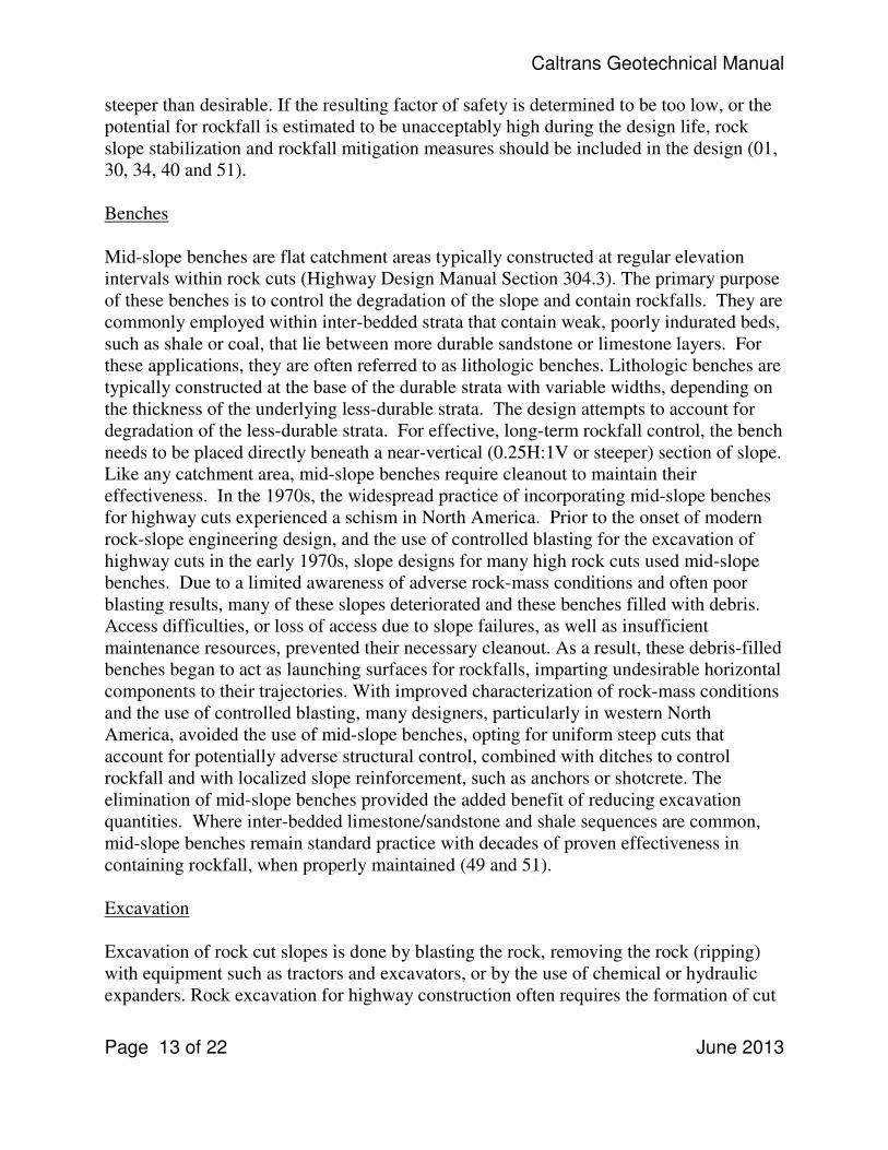
steeper than desirable. If the resulting factor of safety is determined to be too low, or the
potential for rockfall is estimated to be unacceptably high during the design life, rock
slope stabilization and rockfall mitigation measures should be included in the design (01,
30, 34, 40 and 51).
Benches
Mid-slope benches are flat catchment areas typically constructed at regular elevation
intervals within rock cuts (Highway Design Manual Section 304.3). The primary purpose
of these benches is to control the degradation of the slope and contain rockfalls. They are
commonly employed within inter-bedded strata that contain weak, poorly indurated beds,
such as shale or coal, that lie between more durable sandstone or limestone layers. For
these applications, they are often referred to as lithologic benches. Lithologic benches are
typically constructed at the base of the durable strata with variable widths, depending on
the thickness of the underlying less-durable strata. The design attempts to account for
degradation of the less-durable strata. For effective, long-term rockfall control, the bench
needs to be placed directly beneath a near-vertical (0.25H:1V or steeper) section of slope.
Like any catchment area, mid-slope benches require cleanout to maintain their
effectiveness. In the 1970s, the widespread practice of incorporating mid-slope benches
for highway cuts experienced a schism in North America. Prior to the onset of modern
rock-slope engineering design, and the use of controlled blasting for the excavation of
highway cuts in the early 1970s, slope designs for many high rock cuts used mid-slope
benches. Due to a limited awareness of adverse rock-mass conditions and often poor
blasting results, many of these slopes deteriorated and these benches filled with debris.
Access difficulties, or loss of access due to slope failures, as well as insufficient
maintenance resources, prevented their necessary cleanout. As a result, these debris-filled
benches began to act as launching surfaces for rockfalls, imparting undesirable horizontal
components to their trajectories. With improved characterization of rock-mass conditions
and the use of controlled blasting, many designers, particularly in western North
America, avoided the use of mid-slope benches, opting for uniform steep cuts that
account for potentially adverse structural control, combined with ditches to control
rockfall and with localized slope reinforcement, such as anchors or shotcrete. The
elimination of mid-slope benches provided the added benefit of reducing excavation
quantities. Where inter-bedded limestone/sandstone and shale sequences are common,
mid-slope benches remain standard practice with decades of proven effectiveness in
containing rockfall, when properly maintained (49 and 51).
Excavation
Excavation of rock cut slopes is done by blasting the rock, removing the rock (ripping)
with equipment such as tractors and excavators, or by the use of chemical or hydraulic
expanders. Rock excavation for highway construction often requires the formation of cut

Caltrans Geotechnical Manual
Page 14 of 22 June 2013
slope faces that will be stable for many years, and that will also be as steep as possible to
minimize excavation volume and land use. While these two requirements are somewhat
in conflict, the stability of cuts will be enhanced, and the steepest safe slope ratio
increased by using the proper excavation method that does the least possible damage to
the rock behind the final face (01).
Ripping
The physical characteristics that affect rippability are:
1. Frequent planes of weakness
2. Weathering
3. Moisture
4. High degree of stratification
5. Brittleness
6. Low strengths
7. Low seismic refraction velocity
Ripping refers to the removal of rock using tractors, excavators and scrapers. Not all
materials or formations can be ripped. The factors used to determine rippability are
collected during the field investigation. Three important studies need to be done in order
to determine rippability: 1) rock mechanics analysis, 2) geologic site inspection, and 3)
seismic refraction evaluation. Determine the conditions to be considered in determining
whether ripping is appropriate. First and foremost, the geomaterial must be rippable.
Secondly, will blasting damage the slope face or cause damage to the surrounding
structures or environment? Finally, which is more cost effective, blasting or ripping (01,
31 and 45)?
Blasting
The physical characteristics of a rock mass that favor blasting over other methods of
excavation are:
1. Massive
2. Crystalline rock
3. Non-brittle, energy absorbing rock fabrics
4. High strengths
5. High seismic refraction velocity
The preferred method of blasting for rock cut slopes employs lightly loaded, aligned, and
closely spaced blast holes that form the final cut slope face in a manner that minimizes
the effects of the intense detonation gas pressures caused by production blasting. This
technique, which is referred to as presplitting or trim blasting, is performed either before
the main production blasting is detonated (presplit blasting) or after the production

Caltrans Geotechnical Manual
Page 15 of 22 June 2013
blasting (trim blasting). In presplit blasting, the row of control blast holes is detonated to
form a break in the slope along the final cut slope, which serves to vent production gas
pressure and keep it from penetrating and damaging the rock that will form the final cut
face. In cushion blasting, the row of control blast holes is detonated last, in order to trim
off the rock outside the cut slope. The cushion blasting technique is most commonly used
in weaker rock conditions or wherever the thickness of rock to be excavated is less than
15 feet. Controlled blasting is routinely used for rock cuts that are 0.75H: 1V or steeper.
Maintaining blast hole alignments on flat slopes is a limiting factor when considering the
use of controlled blasting (01, 15, 36, 40 and 51).
Rock Slope Stabilization
Mitigation measures to enhance stability include rock reinforcement, drainage, rock
removal, and protection against rockfalls (01, 25, 34, 40 and 51). “Rock Slopes” (40)
serves as a good single reference for stabilization and blasting; however, all of the listed
references provide information on the various stabilization measures.
Reinforcement - Structural reinforcement can be provided by rock bolts, dowels, and
cable lashing. Tensioned rock bolts are used to increase the normal stress along the
discontinuity where sliding is possible, thus increasing the shear strength of the
discontinuity. They may also be used to anchor potentially unstable rock blocks in place.
Dowels are untensioned rock bolts or shear pins used to resist lateral movement of rock
blocks by their shear capacity. Cable lashing uses tensioned cable(s) to increase the
normal force against the face of an isolated block to increase sliding resistance. Other
designs to consider are shear keys and ground anchor walls (01, 02, 46, 49, 40, 51 and
52).
Buttresses - When an overhanging rock is large and it is impractical to remove or
reinforce it, buttresses can be used to support the overhanging rock and increase its
stability. Buttresses serve two functions: (1) protect or retain underlying erodible
material, and (2) support the overhang.
Rock Removal - One method to mitigate an unstable rock slope is to remove the
potentially unstable rock by resloping and unloading the rock mass by rock scaling, trim
blasting, or other excavation techniques. In the construction of new rock cuts, rock
scaling is generally required and treated as incidental to the payment for the type of
excavation performed. Rock trimming can be done with light explosive charges,
hydraulic splitters, chemical expanders or pneumatic hammers (01 and 49).
Drainage - Dewatering to reduce groundwater pressures acting within the rock slope
improves slope stability. Reduced groundwater pressure within a discontinuity increases
the shear strength, while lowering the groundwater height within tension cracks reduces

Caltrans Geotechnical Manual
Page 16 of 22 June 2013
the driving force on a rock block. Proper drainage of rock slopes can be achieved by
installing drain holes (weep holes, horizontal drains) or vertical relief wells. Various
measures, such as construction of surface drains and ditches, minimize water infiltration,
thereby preventing the buildup of groundwater pressures (05, 15, 19, 38 and 48).
Erosion Protection – Hard rock is typically resistant to erosion and/or erodes over long
periods of time i.e., 100’s or more years. Soils, decomposed rocks, highly fractured rocks,
and certain types of rocks that are susceptible to erosion or degradation can erode on the
order of days, weeks and months. When hard rock that is resistant to erosion is underlain
by an erodible or degradable layer the loss of support of the overlying rock may develop
over time through differential erosion, which may create an unstable condition. Stopping
this process can be accomplished by applying shotcrete to the surface of the less resistant
zones or by applying an anchored mesh to the slope face. Weep holes are installed to
prevent the buildup of groundwater pressures behind the shotcrete where the anchored
mesh is free draining. Where applicable (soils and some transitional geomaterials)
sustainable erosion control measures can be implemented (01 and 17).
Protection Measures– Draped mesh systems apply limited normal force against the rock
face, and primarily serves to control the descent of falling rocks into the roadside
catchment area. Barrier systems stop rocks during the rocks’ descent. Barrier types can
range from rigid concrete, timber, gabion walls to flexible fencing (01, 11, 49, 40 and
51).
Standards for Rock Cut Slope Investigation Reports
Rock cut slope preliminary and final recommendations are to be reported in the DPGR
and the GDR respectively. Geotechnical reports must discuss the purpose for the work,
field methods used, and techniques used for data processing and interpretation. Names
and descriptions of any software applications used for data reduction and interpretation
must be presented. Maps and cross-sections must be provided. Features in the geological
models that may affect a project must be noted and discussed in the report. Geological
interpretations and models must be adequately documented.
Reports specifically pertaining to the rock cut slope design should include the stereo net
graphical diagram with the cut slope great circle, the proposed cut slope great circle and
the friction angle circle all shown. The report should also include a table indicating the
excavation characteristics of the rock, i.e, rippable, moderately rippable, difficult ripping
to light blasting, or blasting required. This table should also include earthwork factors as
they relate to the seismic velocity layers and excavation characteristics.

Caltrans Geotechnical Manual
Page 17 of 22 June 2013
Station Velocity
Layer
Thickness Excavation
Characteristics
Earthwork Factors
0+00 to 10+00 V1 10 feet Rippable 0.9
0+00 to 10+00 V2 10 to 30 feet Blasting Req. 1.1
In-house reports should use the standard Caltrans memorandum format. In-house reports
may not include all supporting data used for geological interpretations, since such reports
are typically incorporated as appendices to other Caltrans geotechnical reports. However,
supporting data are archived and can be provided to the geo-professional upon request.
References
The documents below are available in digital format either through the World Wide Web,
Geotechnical Services, or hard copies may be found in the Geotechnical Branch D
library. These documents can also be obtained by contacting the Transportation Library
& History Center, California Dept. of Transportation, 1120 N Street, Rm 1430 (MS 45),
Sacramento, CA 95814, Phone: (916) 654-460, e-mail: [email protected].
1. Andrew, R.D., Bartingale, R., Hume, H., 2011, Context Sensitive Rock Slope
Design Solutions, Publication No. FHWA-CFL/TD-11-002, Federal Highway
Administration, Lakewood, Colorado,
http://www.cflhd.gov/programs/techDevelopment/geotech/css/01-
context_sensitive_rock_slope_design_solutions.pdf
2. Army Corp of Engineers, 1980, Rock Reinforcement, Department of the Army
Corp of Engineers, Office of the Chief, Engineer Manual, EM 1110-1—2907,
http://publications.usace.army.mil/publications/eng-manuals/EM_1110-1-
2907_sec/EM_1110-1-2907.pdf.
3. Association of Engineering Geologists. 1991, Seismic Refraction Data
Interpretation for Engineering and Environmental Investigations, Short Course
No. 7.
4. Association of Engineering Geologists, 1997, Characterization of Weak and
Weathered Rock Masses, Special Publication No. 9.
5. Badger, T., Whitman, T., et al., 2012, Subsurface Drainage for Landslide and
Slope Stabilization, National Pooled Fund Study Project 1078, Washington
Department of Transportation, Olympia, Washington.

Caltrans Geotechnical Manual
Page 18 of 22 June 2013
6. Barton, N., Lienr, L. J., Estimation of Support Requirements for Underground
Excavations, 1977, Design Methods in Rock Mechanics, Proceedings from the
16th
Symposium on Rock Mechanics, ASCE,
http://www.onepetro.org/mslib/servlet/onepetropreview?id=ARMA-75-161.
7. Barton, N.R., Choubey, V., 1978, The Shear Strength of Rock Joints in Theory
and Practice: Rock Mechanics, v.10, no. 1-2, pp 1-54.
8. Bureau of Reclamation, 2001, Engineering Geology Field Manual, Volume I and
II, Second Edition, US Department of the Interior, Washington, D.C.,
http://www.usbr.gov/pmts/geology/geoman.html.
9. Bieniawski, Z.T., 1989, Engineering Rock Mass Classification, Wiley, New York.
10. Billings, M.P., 1972, Structural Geology, 3rd
edition, Prentice Hall.
11. Brawner, C., 1994, Rockfall Hazard Mitigation Methods, Federal Highway
Administration, Publication No. FHWA SA-93-085.
12. California Department of Transportation, 1978, Calculating Earthwork Factors
using Seismic Velocities, FHWA-CA-TL-78-23, Sacramento, California,
http://www.dot.ca.gov/newtech/researchreports/1978-1980/78-23.pdf.
13. California Department of Transportation, 2010, Caltrans Soil and Rock Logging
Manual,
http://www.dot.ca.gov/hq/esc/geotech/sr_logging_manual/page/logging_manual_2
010.pdf.
14. California Department of Transportation, 1977, Correlation of the Seismic
Velocity of Rock to the Ripping Ability of the HD-41 Tractor, Final report,
FHWA-CA-TL-2153-77-10, April 1977, Sacramento, California,
http://www.dot.ca.gov/newtech/researchreports/1976-1977/77-10.pdf.
15. California Department of Transportation, 2003, Caltrans Maintenance Blasting
Manual, Division of Maintenance.
16. California Department of Transportation, 1980, The Effectiveness of Horizontal
Drains, Final Report, Report No. FHWA/CA/TL-80/16, Office of Transportation
Laboratory, Sacramento, California.
17. California Department of Transportation, 2010, Key Concepts of Sustainable
Erosion Control, Technical Guide, CTSW-RT-09-055.1.0.12, Caltrans.

Caltrans Geotechnical Manual
Page 19 of 22 June 2013
18. California Department of Transportation, 1973, Design Variables for Cut Slopes,
Final Report CA-DOT-TL-2882-1-73-27, Office of the Transportation Laboratory,
Sacramento, California.
19. Cook, D.I., Santi, P.M., Higgins, J.D., Horizontal Landslide Drain Design: State of
the Art and Suggested Improvements, 2008, Environmental & Engineering
Geoscience, Vol. XIV, No. 4, November 2008, pp. 241–250,
http://inside.mines.edu/~psanti/paper_pdfs/Cook%20Horizontal%20Drain%20Stat
e%20of%20the%20Art.pdf .
20. Davis, G.W., 1996, Structural Geology of Rocks and Regions, John Wiley &
Sons.
21. Deer, D.U., Miller, R.P., 1966, Engineering Classification and Index Properties for
Intact Rock, University of Illinois, Technical Report No. AFWL-TR-65-116, US
Department of Commerce, National Technical Information Service, Springfield
Va,
http://oai.dtic.mil/oai/oai?verb=getRecord&metadataPrefix=html&identifier=AD0
646610.
22. Emery, C.L., 1966, The Strain in Rocks in Relation to Highway Design, Highway
Research Record, No. 135, Rock Mechanics, Highway Research Board, Division
of Engineering National Academy of Sciences, p 1-9,
http://trid.trb.org/view.aspx?id=120973.
23. FHWA, 1997, Subsurface Investigations, Publication HI-97-021, National
Highway Institute, Federal Highway Administration,
http://isddc.dot.gov/OLPFiles/FHWA/007919.pdf.
24. FHWA, 2002, Evaluation of Soil and Rock Properties FHWA-IF-02-034,
Geotechnical Engineering Circular No. 5, AFWL-TR-65-115,
http://isddc.dot.gov/OLPFiles/FHWA/010549.pdf.
25. FHWA, 1979, Rock Slope Engineering, Part C, Approach and Techniques in
Geologic Structural Analysis, Federal Highway Administration, FHWA –T8-79-
208.
26. FHWA, 1997, Design Guidance: Geotechnical Earthquake Engineering for
Highways, Report No. FHWA-SA-97-077, Federal Highway Administration,
http://isddc.dot.gov/OLPFiles/FHWA/011367.pdf

Caltrans Geotechnical Manual
Page 20 of 22 June 2013
27. FHWA, 1981, Roadway Damage During the San Fernando, California Earthquake
of Feb. 9, 1971, Final report FHWA/CA/TL/80/17, Office of the Transportation
Laboratory, Sacramento, California.
28. GEO-SLOPE International, Ltd., SLOPE-W, 1400, 633 6th Avenue SW Calgary,
Alberta, Canada T2P 2Y5, http://www.geo-slope.com.
29. Geotechnical Engineering Office, 1997, Mineralogy and Fabric Characterization
and Classification of Weathered Granitic Rocks in Hong Kong, GEO Report No,
41, Civil Engineering Department, Hong Kong,
http://www.cedd.gov.hk/eng/publications/geo_reports/doc/er41.pdf.
30. Goodman, R.E., Introduction to Rock Mechanics, 1980, University of California
Berkeley, Berkeley, California.
31. Handbook of Ripping, 12th
Edition, Caterpiller, Inc., Peoria, Illinois, 2000.
32. Highway Research Record. 1966, Rock Mechanics, National Academy of
Sciences, Number 135, 1966,
http://openlibrary.org/works/OL6291280W/Stability_of_rock_slopes.
33. Highway Research Record, 1963, Stability of Rock Slope, No. 17, National
Academy of Sciences, Publication 1114,
http://openlibrary.org/books/OL5931769M/Stability_of_rock_slopes.
34. Hoek, E., Bray, J.W., Rock Slope Engineering Revised 3rd Edition (ISBN 0-419-
16010-8), 1980, Institute of Mining and Metallurgy, E&FN Spon Press.
35. Hoek, E., Rock Mass Properties for Underground Mines, 2001, Underground
Mining Methods: Engineering Fundamentals and International Case Studies,
Colorado: Society for Mining, Metallurgy, and Exploration (SME),
http://www.rocscience.com/hoek/references/H2001d.pdf.
36. Konya, 2000, FHWA, “Rock Blasting and Overbreak Control,” NHI Course No.
13211, FHWA-HI-92-00, http://isddc.dot.gov/OLPFiles/FHWA/012844.pdf.
37. Long, A.E., Merrill, R.H., Wisecarver, D.W., 1966, Stability of High Road Bank
Slopes in Rock-Some Design Concepts and Tools, Highway Research Record, No.
135, Rock Mechanics, Highway Research Board, Division of Engineering
National Academy of Sciences, p 10-26, http://trid.trb.org/view.aspx?id=120974.

Caltrans Geotechnical Manual
Page 21 of 22 June 2013
38. Long, A.E., Michael, T.L., 1991, Exploration, Design, and Construction of
Horizontal Drain Systems, Transportation Research Record No. 1291. Washington
DC.
39. Marinos, P., and Hoek, E., GSI: A Geologically Friendly Tool for Rock Mass
Strength Estimation, 2000, GeoEng 2000, International Conference on
Geotechnical and Geological Engineering, Volume 1, Melbourne, Australia,
http://lib.hpu.edu.cn/comp_meeting/ICGGE%B9%FA%BC%CA%B5%D8%D6%
CA%B9%A4%B3%CC%BB%E1%D2%E9%C2%DB%CE%C4%CA%FD%BE
%DD%BF%E2/PAPERS/INVITED/MARINOS.PDF.
40. Munfakh, G., Wyllie, D., Mah, C.W., 1998, Rock Slopes, Report No. FHWA-HI-
99-007, NHI Course No. 13235 - Section 5, National Highway Institute, Federal
Highway Administration, Washington, D.C.
41. Ragan, D. M., 1985, Structural Geology, An Introduction to Geometrical
Techniques, 3rd
edition, John Wiley & Sons.
42. RockWare, Inc., RockPack III, 2221 East Street #1, Golden, Colorado, 8040,
http://www.rockware.com.
43. Schuster, R.L., Krizek, R.J., Editors, 1978, Landslides Analysis and Control,
pages 196-197, TRB Special Report 176, Transportation Research Board, National
Research Council, National Academy Press, Washington, D.C.
44. State of California, 1973, Shallow Seismic Techniques, Highway Research
Record, Final Report, Department of Public Works, Division of Highways,
Materials and Research Department, Research report CA-HY-MRR-2951-1-73-18,
http://www.dot.ca.gov/newtech/researchreports/1973/73-18.pdf.
45. State of California, 1972, Correlation of Seismic Velocities with Earthwork
Factors, Final Report, Department of Public Works, Division of Highways,
Materials and Research Department, Research report CA-HY-MRR-2103-4-72-37,
http://www.dot.ca.gov/newtech/researchreports/1972/72-37.pdf.
46. State of California, 1975, Rebound of a Deep Shale Cut, Final Report, ,
Department of Public Works, Division of Highways, Materials and Research
Department, Research Report CA-Dot—TL-2722-1-75-11,
http://www.dot.ca.gov/newtech/researchreports/1974-1975/75-11.pdf.

Caltrans Geotechnical Manual
Page 22 of 22 June 2013
47. State of California, 1977, Evaluation of Steep Cut Slopes in Poorly Consolidated
Sediments, Department of Public Works, Division of Highways, Materials and
Research Department, Final Report, CA-TL-2132-77-31,
http://www.dot.ca.gov/newtech/researchreports/1976-1977/77-31.pdf.
48. State of California, 1955, Horizontal Drains on California Highways, Materials
and research Department, California Division of Highways, Sacramento,
California.
49. Turner A.K., Schuster, R.L., 2012, Rockfall Characterization and Control, Chapter
1, Transportation Research Board, National Academy of Sciences, Washington,
D.C., www.TRB.org/Rockfall.
50. Turner A.K., Schuster, R.L., 1996, TRB Special Report 247 Landslides,
Investigation and Mitigation, Transportation Research Board, National Academy
of Sciences, Washington, D.C.
51. Wyllie, D.C., Mah, C.W., 2004, Rock Slope Engineering, Civil and Mining,
(ISBN0-415-28000-1), Fourth Edition, SPON Press, Madison, New York.
52. Wyllie, D., 1992, Foundations on Rock, E&FN Spon Publishers.