Geotechnical Instrumentation News June 2003 - BiTech
19
Geotechnical Instrumentation News John Dunnicliff Introduction This is the thirty-fifth episode of GIN. Two articles this time, and some discus- sions. Measurement of Pore Water Pressures (as Opposed to Pore Gas Pressures) Four discussions of Arthur Penman’s article, published recently in Geotechnical News (December 2002, pp 43-49) are published immediately after this ‘column’, together with the author’s reply. My discussion includes two quota- tions from Jim Sherard’s definitive 1981 paper, “Piezometers in Earth Dam Impervious Sections”. The paper may not be readily available to some readers of GIN – if anyone wants to read the other 12 of the 14 “Summary of Main Points”, please let me know, and I’ll e-mail them to you. Two of the discussions (Martin Beth’s and mine) refer to an ongoing project in Europe – a cut slope in Boul- der clay. Negative pore water pressures are being measured, using flushable vi- brating wire piezometers with high air entry filters, to address concerns about the stability of the slope. I’ve arranged with the engineers who are responsible for those measurements to send me a case history for GIN when there are enough data. The following is a summary of GIN articles and discussions on the subject of measurement of pore water pressure as opposed to gas pressure: • Penman (2002). Measurement of Pore Water Pressures in Embank- ment Dams. December, pp 43-49. • Ridley (2003). Recent Develop- ments in the Measurement of Pore Water Pressure and Suction. March, pp 47-50. • Thomann, Goldberg and Napolitano (2002). Are Those Pore Pressure Readings Correct? March, pp 50-53. • Sellers (2003). Discussion of Pen- man (2002). June (this issue). • Dunnicliff (2003). Discussion of Penman (2002). June. • Mikkelsen (2003). Discussion of Penman (2002). June. • Beth (2003). Discussion of Penman (2002). June. • Penman (2003). Author’s Reply to the above four discussions. June. • Long and Menkiti. Future article de- scribing measured pore water suctions in a cut slope in Boulder clay. Time Domain Reflectometry In the previous episode of GIN I said that it was time we had a comprehen- sive update on time domain reflectometry (TDR). The geotechnical practitioners who I be- lieve know most about this in North America are, in alphabetical order, Chuck Dowding, Bill Kane and Kevin O’Connor. Here are two articles by the trio, together with Matthieu Dussud. The first describes the concept of TDR and includes a case history of deforma- tion of a landfill slope. The second gives a crisp summary of lessons learned, relating both to sensor cable installation and to the instrumentation itself. The March 2003 Instrumentation Course at Cocoa Beach, Florida The course was attended by 58 regis- trants, and I believe that we all learned enough to justify our being there. Provi- sional plans for the next course are for West Coast of Florida, in the Tampa/St. Petersburg/Clearwater area, in March 2005. If you’d like to be on the mailing GEOTECHNICAL INSTRUMENTATION NEWS Geotechnical News, June 2003 Variable Year 1997 1999 2002 2003 Month November November March March Publicity Old style - primarily paper ads and mailing of brochures New style - paper ads, bro- chures plus web sites and e-mails Ralph Peck was present No No Yes Yes Number of registrants 34 29 59 58
Transcript of Geotechnical Instrumentation News June 2003 - BiTech

Geotechnical Instrumentation News
John Dunnicliff
IntroductionThis is the thirty-fifth episode of GIN.Two articles this time, and some discus-sions.
Measurement of Pore WaterPressures (as Opposed to PoreGas Pressures)Four discussions of Arthur Penman’sar t ic le , publ ished recent ly inGeotechnical News (December 2002,pp 43-49) are published immediatelyafter this ‘column’, together with theauthor’s reply.
My discussion includes two quota-tions from Jim Sherard’s definitive1981 paper, “Piezometers in Earth DamImpervious Sections”. The paper maynot be readily available to some readersof GIN – if anyone wants to read theother 12 of the 14 “Summary of MainPoints”, please let me know, and I’lle-mail them to you.
Two of the discussions (MartinBeth’s and mine) refer to an ongoingproject in Europe – a cut slope in Boul-der clay. Negative pore water pressuresare being measured, using flushable vi-brating wire piezometers with high airentry filters, to address concerns aboutthe stability of the slope. I’ve arrangedwith the engineers who are responsiblefor those measurements to send me acase history for GIN when there areenough data.
The following is a summary of GINarticles and discussions on the subjectof measurement of pore water pressureas opposed to gas pressure:• Penman (2002). Measurement of
Pore Water Pressures in Embank-ment Dams. December, pp 43-49.
• Ridley (2003). Recent Develop-ments in the Measurement of PoreWater Pressure and Suction. March,pp 47-50.
• Thomann, Goldberg and Napolitano(2002). Are Those Pore PressureReadings Correct? March, pp 50-53.
• Sellers (2003). Discussion of Pen-man (2002). June (this issue).
• Dunnicliff (2003). Discussion ofPenman (2002). June.
• Mikkelsen (2003). Discussion ofPenman (2002). June.
• Beth (2003). Discussion of Penman(2002). June.
• Penman (2003). Author’s Reply tothe above four discussions. June.
• Long and Menkiti. Future article de-scribing measured pore watersuctions in a cut slope in Boulderclay.
Time Domain ReflectometryIn the previous episode of GIN I said
that it was time we had a comprehen-s ive update on t ime domainref lec tomet ry (TDR) . Thegeotechnical practitioners who I be-lieve know most about this in NorthAmerica are, in alphabetical order,Chuck Dowding, Bill Kane and KevinO’Connor. Here are two articles by thetrio, together with Matthieu Dussud.The first describes the concept of TDRand includes a case history of deforma-tion of a landfill slope. The secondgives a crisp summary of lessonslearned, relating both to sensor cableinstallation and to the instrumentationitself.
The March 2003Instrumentation Course atCocoa Beach, FloridaThe course was attended by 58 regis-trants, and I believe that we all learnedenough to justify our being there. Provi-sional plans for the next course are forWest Coast of Florida, in the Tampa/St.Petersburg/Clearwater area, in March2005. If you’d like to be on the mailing
GEOTECHNICAL INSTRUMENTATION NEWS
Geotechnical News, June 2003
Variable Year
1997 1999 2002 2003
Month November November March March
Publicity Old style - primarily paper adsand mailing of brochures
New style - paper ads, bro-chures plus web sites and
e-mails
Ralph Peckwas present
No No Yes Yes
Number ofregistrants
34 29 59 58

list for this, please let me know.You know how difficult it is to inter-
pret instrumentation data (to determinethe relationship between cause and ef-fect) when there are too many variables!Please study the data in the table onpage 41.
Any interpretations? Do you think it
was the month?
ClosurePlease send contributions to this col-umn, or an article for GIN, to me as ane-mail attachment in MSWord, [email protected], or byfax or mail:
Little Leat, Whisselwell, Bovey Tracey,Devon TQ13 9LA, England.Tel. and Fax +44-1626-832919.
Past the lips and over the gums, look outstomach, here she comes (USA).Thanks to Charles Daugherty for this.
Discussions of“Measurement of Pore Water Pressuresin Embankment Dams”
Arthur D. M. Penman
Geotechnical News, Vol. 20 No. 4,December 2002, pp 43-49
Barrie Sellers
First I would like to thank Arthur Pen-man for his very interesting and infor-mative article. I certainly learned a lotfrom it. There are a couple of pointswith which I would like to take issue.These mainly revolve around the ex-pressed need for high air entry (HAE)filters on diaphragm type piezometers.
I am not convinced, for instance, thatthe results shown in Figure 7 (the figurethat shows that pore pressure readingswith a coarse filter were higher thanthose with a fine HAE filter, atChelmarsh Dam) could not have beendue to a measured suction merely in thepores of the HAE filter. We certainlyknow that a saturated HAE filter will,on exposure to air, create a vacuum in-side a piezometer.
Also I remain unconvinced that,from a stability viewpoint, the measure-ment of suction pressures is at all im-portant. To my way of thinking, the onlything that suction pressure achieves isan increase in the shear strength of thesoil, due to a pulling together of the soilgrains. Granted that this is desirable, butstill, the main cause of instability is thehydraulic head of the ground water ex-erted by the totality of the water in theinterconnected pores. This pressure,along with seepage pressure, acting in-
ternally in the soil mass at the edges of afill or embankment, is the destabilizingpressure, and is the one that needs to bemeasured. And the measurement can bemade quite adequately using apiezometer equipped with a standardlow air entry filter.
If the objection is raised that this willperhaps measure the pore air (or gas)pressure then I contend that the pore air
pressure can be only slightly higherthan the pore water pressure and willlead to a calculation erring on the side ofsafety.
I am certain that a conventional dia-phragm-type piezometer will never beable to measure suctions in excess of 1bar on account of the cavitation that willtake place in the space between filterand diaphragm. This same water-filledspace also, perhaps, makes nonsense ofthe expressed need to have the filter inintimate contact with the surrounding
soil. Whether or not there is a wa-ter-filled space on the outside of thepiezometer, there is always going to be awater-filled space on the inside throughwhich any capillary suction must betransmit ted to the piezometerdiaphragm.
I think it highly probable that anHAE filter in a partially saturated soilwill, at some point, itself become par-
tially saturated and the resultant airblockage will prevent the accuratetransmission of ground water pressuresto the piezometer diaphragm – anotherexample of the Jamin, (felicitousname), effect mentioned by Penman.
To sum up: I am concerned that anyunusual or academic requirement forHAE filter stones may become en-trenched in standard practice with littleor no tangible benefit to compensate forthe greater difficulty in saturating thefilter stones and in installation proce-dures, and for the opportunity for spuri-
GEOTECHNICAL INSTRUMENTATION NEWS
Geotechnical News, June 2003
I am concerned that any unusual oracademic requirement for high air entry filter stonesmay become entrenched in practice with no benefit...

NEW - RST AD 4 colour NEW electronic file sent to Friesensfor June issue
GEOTECHNICAL INSTRUMENTATION NEWS
Geotechnical News, June 2003

ous readings to occur due to meniscieffects in the HAE filter stone itself.
Barrie Sellers, President, Geokon Inc.,48 Spencer Street, Lebanon, NH 03766,
Tel. (603) 448-1562, Fax (603)448-3216, email: [email protected]
John Dunnicliff
The pore water/pore gas issue, and theassociated use of high air entry (HAE)filters is one that confuses many of us.The article by Arthur Penman helps toclarify the issue, and I thank him verymuch for this. But I admit to some re-maining confusion.
For some applications, the need forHAE filters (together with the associ-ated requirements about saturation andintimate soil/filter contact that Penmanpoints out in his final paragraph) isclear. I think it is useful to paraphrasepart of what I wrote in my March 2003GIN ‘column’, to illustrate why this isclear, before discussing the special caseof embankment dams:• The article by Andrew Ridley
[Geotechnical News, March 2003,pp 47-50] helps us to understand thebasic issues relating to negative porewater pressure (soil suction) and de-scribes recent developments of mon-itoring instrumentation, including a‘flushable’ piezometer, with a HAEfilter. The flushable piezometer is de-signed to minimize the presence ofair in the piezometer cavity and toprovide a means of removing it if andwhen it enters the cavity.
• The article by Thomas Thomann etal [Geotechnical News, March 2003,pp 50-53] describes measurementsin an organic clay layer below alarge embankment in Staten Island,New York. Piezometric data werecollected and used to estimate con-solidation stresses and undrainedshear strength, and were then used instability analyses. The article clearlydemonstrates the need to use HAEfilters when gas is present in thepores.
• A third article will be published laterin GIN, giving an ongoing case his-tory of a project in Europe – a cutslope in Boulder clay. Negative porewater pressures are being measured,using flushable vibrating wire
piezometers with HAE filters, to ad-dress concerns about the stability ofthe slope.Now to the special case of embank-
ment dams. While interacting with Ar-thur Penman and Barrie Sellers duringpreparation of Penman’s December2002 article and these discussions, the
latter reminded me of Jim Sherard’s de-finitive 1981 paper in which he con-cludes (changes to bold text are mine):• “In impervious embankments with
clayey fines, which have appreciableinitial capillary suction, the air pres-sure is always greater than the waterpressure. The difference is generallynot great when the water pressure isabove atmospheric pressure. Thereare very few situations where thedifference between measured airpressure and true water pressurecould have a significant influenceon the evaluation of the behavior ofa dam.”
and• “When vibrating wire or pneumatic
piezometers are used for routine in-strumentation in the impervious sec-tions of embankment dams, it isconsidered reasonable currentpractice to use coarse porous tips(low air entry value).”Further, Sherard has also written:
• “The compacted fill in an embank-ment dam may remain unsaturatedfor a prolonged period after the res-ervoir is filled, and in fact the fill maynever become permanently satu-rated by reservoir water”.
This last quotation is from page 145 inthe red book – Jim Sherard and ArthurPenman were my much-needed helperswhen writing the chapter on instrumen-tation of embankment dams.
In summary to Sherard’s views, herecommends use of low air entry (LAE)rather than HAE filters on vibratingwire piezometers installed in the coresof embankment dams, even though heaccepts long-term unsaturation of thecore material.
These views are different from thoseexpressed by Penman in his last para-graph: “Modern diaphragmpiezometers for installation in the coresof embankment dams should besupplied with high air entry filters...”.Therein lies my confusion, particularlyas I have always greatly respected theviews of both Sherard and Penman.
So I will close with two questions toArthur Penman (some editorial prerog-ative here, because discussions are sup-posed to be discussions, and notquestions!):
If we want to monitor ‘pore pressure’in the core of an embankment dam, us-ing vibrating wire piezometers, (a) forthe purpose of monitoring consolida-tion and stability during constructionand/or (b) for monitoring long-termpore pressures as a health check, shouldwe use LAE or HAE filters? And, ofcourse, why?
ReferenceSherard, J.L., (1981), “Piezometers in
Earth Dam Impervious Sections”, inProc. ASCE Symp. on Recent De-velopments in Geotechnical Engi-neering for Hydro Projects, F.H.Kulhawy (Ed.), ASCE, New York,pp 125-165.
John Dunnicliff,email: [email protected]
GEOTECHNICAL INSTRUMENTATION NEWS
Geotechnical News, June 2003
If we want to measure‘pore pressure’ .… should we
use LAE or HAE filters?And, of course,
why?

P. Erik Mikkelsen
The paper by Dr. Penman beautifullydescribes the physics of pore air andwater pressure in unsaturated soil andthe need for saturated high air entry fil-ters. The detailed requirements for hy-draulic piezometer hardware and fieldprocedures using Bishop tips anddeaired water with the Nold DeAeratorare extremely well explained. It is quiteclear from his discussion that the hy-draulic piezometer system needs spe-cial care and attention to detail in all as-pects of installation, operation andmaintenance for it to work properly.
Unfortunately the experience withhydraulic piezometers in North Amer-ica has been much less than satisfactory.Lack of attention to the details de-scribed by Dr. Penman has probablybeen the main problem. In fact it hasbeen so dismal that no US manufacturerof geotechnical field instrumentationmakes the equipment. Instead the trendhas been toward the use of pneumaticand vibrating wire pressure (VWP) sen-sors. High air entry filters are some-times specified, but there are seriouspractical problems with their use. Theysimply dry out over a few months(through a diffusion process) withoutany facility for re-saturation. Thereforeit is reasonable to use standard (low airentry) filters that do not require specialsaturation in the field. Under such cir-cumstances no pore water suction willbe sensed and only the air (gas) pressurewill be registered. However, accordingto Figure 7 in Penman’s paper it is rea-sonable to expect that pore air and waterpressures merge at a positive pressurelevel of 0.5 to 1 atmospheres when airdissolves into water. That is significantbecause, after all, it is usually high porewater pressures that are of concern, notlow suction in the pore water.
Fortunately there is another simpleborehole installations method that canbe used to improve measurements incompacted embankments. The recenttrend towards the installation of VWPsensors in fully-grouted boreholeswould also be applicable to measuringpore water pressure in the lower pres-
sure and suction range. Reportedly, suc-tion to – 52kPa below ambientatmospheric pressure has recently(Geotec Co. Ltd./ Interfels, 2002) beenmeasured by fully grouted VWPs inboreholes above the water table underembankment fills. Not only would thismethod simplify the installation pro-cess in embankments, it nearly meets allof the requirements listed by Dr. Pen-man. The VWP cavity could still not bere-saturated, but the sensor could beprotected from drying out bysurrounding it with a greatly increasedvolume of grout.
The cement-bentonite grout to beused was the subject of the article pre-ceding Dr. Penman’s in the same issue
of GIN (Mikkelsen, 2002). This type ofcement-bentonite grout has propertiessimilar to a saturated high air entry fil-ter. It uses no sand pocket and is in inti-mate contact with the soil. The grout isfully saturated. A large volume of groutwould give up its saturation very slowly,much slower than a filter the size of aBishop tip. The volume of grout sur-rounding a VWP installed in the core ofthe dam should be large enough to keepthe sensor cavity saturated from thetime of installation to the first filling ofthe reservoir.
For example, an embankment VWPwith a standard filter should bepreinstalled inside a cylinder of ce-ment-bentonite grout (10-cm diameterby 25-cm high), kept saturated andcured for a minimum of 7 days. Calibra-tion checks should also be carried out in
a lab environment before the field in-stallation to ensure that the VWP re-sponds correctly inside the groutcylinder. The response of the VWP inthe grout could, for example, be testedin a 2 to 3 meter tall 15-cm diameterpipe against a known head of water(Tofani, 2000). The installation in theembankment core should be made at thecenter of an excavated cubical pit. A pit,60 cm cubed, would hold about 200 li-ters (50 gal.) of grout and is a volumethree orders of magnitude greater than aBishop tip volume (about 0.2 liters). Toimprove the saturation situation further,the pit could be filled with water prior toinstallation and the installation andgrouting done “in the wet”. In anyevent, the exposed sides of the pit mustbe kept moist. Another variation on theinstallation particularly in silty andsandy soil would be to line the bottomand sides of the pit with polyethylenesheeting so only the top of the “groutcube” would be in direct contact withthe embankment soil. This would effec-tively retard the tendency for drainingand drying of the grout. The groutshould be allowed to cure for a coupleof days before production compactionresumes above the pit.
In conclusion, the purposes of thisdiscussion are (1) to show appreciationfor the tremendous contribution Dr.Penman has made to our profession onthis subject over the last 50 years and (2)to get people moving ahead withgrouted installations, something Dr.Penman did not mention. However, Ihave l i t t le hope that hydraul icpiezometers will have a renaissance inthe US based on his article. But hisknowledge along with the work of otherresearchers on this subject in the UKhelps us chart a revised course towardsbetter understanding and improvedmeasurements of low pore waterpressures in North America.
ReferencesGeotec Co. Ltd./ Interfels (2002). Per-
sonal communication.Mikkelsen, P.E., (2002). Cement-Ben-
GEOTECHNICAL INSTRUMENTATION NEWS
Geotechnical News, June 2003
...the purpose of thisdiscussion is...
to get people movingahead with grouted
installations...

tonite Grout Backfill for BoreholeInstruments. Geotechnical News,Vol. 20, No. 4, December, pp 38-42.
Tofani, G.D., (2000). Grout-in-PlaceInstallation of Slope Inclinometers
and Piezometers, in Seminar onGeotechnical Field Instrumentationat University of Washington, Am.Society of Civil Engineers, SeattleSection, Geotechnical Group.
P. Erik Mikkelsen, Consulting Engineer,Geometron, 16483 SE 57th Place,Bellevue, WA 98006,Tel: (425) 746-9577,email: [email protected]
Martin Beth
I have read Dr. Penman’s December ar-ticle about pore pressure measurement.I read it with great interest. It managesthe incredible thing of making the sur-face tension story clearly understand-able to most, and summarises very wellthe state-of-the-art in pore pressuremeasurements. Congratulations!
I have some comments about instal-lation of piezometers, in the hope that
they can be useful for the discussion.Our company is convinced by the
theory of the fully-grouted method, andwe advocate it on sites where the condi-tions are difficult for the conventionalmethod (for example, multiple installa-tions in one borehole, installations un-
der large water pressure and water flow,etc). For simple sites, we stick to theconventional method, mainly because itis a difficult task to convince the otherparties about the fully-grouted method.
I will mention a modest “half” casehistory from Europe. Half because I amnot able to give you the full picture, aswe prepared a design for a job but un-fortunately lost it at the last minute.
An excavation is to be held in placemainly by the suction pressures in thelocal clay, during the constructionphase. The specifications required in-stallation of vibrating wire piezometersinside Plaster of Paris filters, with twotubes to allow “re-saturation” from thesurface. That was to deal with the possi-bility of the piezometer filter and Plas-ter of Paris becoming unsaturated. Wewere worried about two things:• Installation of Plaster of Paris at the
bottom of a borehole - a difficultthing to do.
• The risk of measuring hydrostaticpressure in the re-saturation tubesfor a long time after flushing.
So we proposed a fully grouted-in
method, and had Geokon devise aflushable piezometer for us, with sole-noid valves near the tip, so that therewould not be the problem of hydrostatichead. We also based our design on thefact that the high air entry filter wouldbe replaced by the grout surroundingthe sensor.
A “cost saving” element during thenegotiation with the main contractorwas to put more than one piezometerper borehole, which is possible with thefully-grouted method. Because of theextremely low permeability of the clay(from memory, 1x10⁻¹⁰ to 1x10-11
m/sec.), we were planning to design aspecial grout.
Anyway, my part of the story stopshere as the main contractor, who wasour prospective client, finally gave thecontract to another company.
Martin Beth, Operations Manager,Soldata Group, 294 avenue GeorgesClemenceau, 92000 Nanterre, France,Tel. +33-1-41-44-85-10,Fax +33-1-41-44-85-11,email: [email protected]
Author’s Reply
ResponseI am pleased to see the interest in my ar-ticle and thank Barrie Sellers, JohnDunnicliff, Erik Mikkelsen and MartinBeth for their contribution to the discus-sion. I am delighted that I have beenable to shed light on the behaviour ofsurface tension and the part it plays inpreventing gases from entering satu-rated fine pored filters. I thank thediscussers for their kind remarks aboutmy contribution to our profession dur-ing the past 50 years.
PropertiesThere are a number of things aboutwhich we should be clear when consid-ering the measurement of pore pres-sures in partly saturated soils. We havediscussed the surface tension of waterand mentioned that it can have a value of75mN/m, which provides strong resis-tance against the penetration of a gasinto the small diameter holes on the sur-face of a saturated fine pored filter, thatform the entrances into the pore spaceof the filter. When that surface ispressed into intimate contact with a wet
soil, water in the soil can contact the wa-ter in the filter, making a continuumwith no intermediate surface, so that thepressures of the two waters can reachequilibrium.
Another property of water is its hightensile strength. This has been well de-scribed by Andrew Ridley (2003) in hisrecent article published in the Marchepisode of GIN, who has shown that ithas a theoretical value of about 50 MPa(7200 lb/in2) and that more than 100years ago a value of about 700 kPa (100lb/in2 ) was measured on carefully
GEOTECHNICAL INSTRUMENTATION NEWS
Geotechnical News, June 2003
Our company is convincedby the theory of the
fully-grouted method,and we advocate it...

de-aired water. All natural water con-tains air, as those who keep ornamentalfish in a goldfish bowl know very well.Their behaviour soon tells you whenthey have insufficient oxygen. You canextract air from water by reducing pres-sure, and when your suction approachesa vacuum, the water appears to boil. Be-cause of this it is commonly believedthat water cannot be subjected tosuctions greater than one atmosphere.But, as Andrew Ridley has pointed out,to form a cavity within water requiresbreaking the bond between adjacentmolecules, which as we have seen fromsurface tension, is a strong bond, thatprovides the tensile strength of the wa-ter. It is most difficult to enclose waterin a cavity such as that formed betweenthe diaphragm and the saturated finepored filter of a piezometer, without in-cluding some gas adhering to the sur-face or hidden in a corner or crevice.The laboratory piezometer developed atImperial College (Ridley and Burland1993, and Ridley, 2003) was designedto have a water cavity of only 3 mm3 andit was made to an exceptionally highstandard by the laboratory workshopsso that the surfaces of the stainless steelbody of the instrument were verysmooth, free from re-entrant cornersand crevices. It was fitted with a finepored filter able to withstand a blowthrough pressure of 1500 kPa (220lb/in2), and was found, perhaps a littlesurprisingly, to be able to measuresuctions of –1200 kPa (-170 lb/in2).
PrinciplesAnother thing about which we shouldbe clear is the principle of effectivestress. It was first stated by Terzaghi in1923, again in his Erbaumechanik in1925 and in English in 1936 (Terzaghi,1936). It has been given in most text-books on Soil Mechanics, and relates tosaturated soil. Civil engineers havetended to use it rather blindly for allsoils although it is well known thatmany soils above the water table are notfully saturated. Engineering fills placedand compacted by machinery as in em-bankment dams are invariably partlysaturated. If not very well compacted,they may suffer collapse settlements onwetting, leading to the comments made
by Jennings and Burland (1962) thatthey do not follow the principle of effec-tive stress. The term “effective” is usedbecause this stress is effective in con-trolling both strength and consolida-tion. It is the total stress minus the porepressure. Total stress may be estimatedfrom the weight of soil above the givenpoint. But without knowledge of thepore pressure, the vital effective stressremains unknown. For partly saturatedsoils Bishop (1959) proposed his chitheory, using values of both pore gasand pore water pressures.
Intake FiltersStandpipe piezometers were the firsttype to be used in embankment dams.They require a considerable volume ofwater to flow through their intake filters
to record changes of pressure and it be-came usual when they were installed inboreholes to surround their filters withsand, converting their filters to quitelarge cylinders of sand. The two tubehydraulic piezometers required a verymuch smaller volume of water for theiroperation, so their intake filters could besmall. Vibrating wire piezometers re-quire negligible volumes of water. Theeffect of the volume of water needed tooperate a piezometer and the size of itsintake filter on its response time hasbeen considered by Penman (1960).
Sherard (1981) regards vibratingwire piezometers as “no-flow” instru-ments, i.e. the volume of water neededto operate them is infinitely small sothat intake filters of low permeabilityand relatively small size are suitable.They may be bedded into the soil duringinstallation by coating with a slurry ofthe soil at about its liquid limit. This en-sures intimate contact with the soil to
give an air free installation that will im-mediately measure the exist ingsuctions. The use of sand pockets forstandpipe piezometers became so in-grained that specifications have beendrawn up showing how the sand shouldbe placed and how a seal should beformed above the pocket in a borehole,using bentonite pellets plus bentonitegrout. Such pockets were then providedfor all types of piezometer, includingthe diaphragm types that clearly do notneed large intake filters. Sherard getsquite excited about it and says veryclearly that these sand pockets shouldnever be used for vibrating wirepiezometers.
Fine Pored (High Air Entry)Intake FiltersThe need for fine pored filters wasbrought home to us during the con-struction of the 41 m high Usk em-bankment dam in Wales during1950-54. I installed twin tube hydrau-lic piezometers in the boulder clay fillin July 1951 at a position that would beat mid height of the first years fill. Thedam was being built during three sum-mer seasons: placing the boulder clayduring the winter months was not fea-sible. These early measurements ofpore pressure in a British dam arousedconsiderable interest, most particu-larly when the measured values ex-ceeded the overburden pressure. Usingtoday’s terms, rμ exceeded 150%.Head of the Geotechnical Section atBRS was Dr Cooling, who had workedwith suction plates during studies ofbuilding stone, and suggested that thecoarse pored filters that we were using,would permit the pressure of the gas(air) in the part saturated fill to affectthe readings. An account of the Uskconditions was given by Penman(1979). We began looking for suitablefine pored materials for making the fil-ters, but were concerned that flat discsof the type we were using would notmake good contact with the fill duringinstallation. Eventually Bishop, at Im-perial Collage persuaded a ceramicmanufacturer to make tapered cylindri-cal filters from material with smallenough pores to provide a “blowthrough” pressure of 200 kN/m2 (30
GEOTECHNICAL INSTRUMENTATION NEWS
Geotechnical News, June 2003
Engineering fills placedand compacted by
machineryas in embankment dams
are invariably partlysaturated.
lb/in2 ) but at the same time have a per-meability of 3 x 10⁻⁶ cm/sec. The re-sulting unit is shown by Fig.1 of the pa-per and was first used in Selset damduring 1958/9. News of this develop-ment quickly spread throughout thegeotechnical field and soon many othercountries were using fine pored filtersfor their piezometers.
The experience of measuring porepressures in Norwegian embankmentdams has been described by DiBiagioand Kjærnsli (1985) and DiBiagio andMyrvoll (1985). For the 93m Hyttejuvetdam seven types of piezometer wereused in order to assess the most suitable.This enabled comparisons to be made ofthe pressures measured by both coarseand fine pored filters. The conicalshaped vibrating wire piezometershown by Fig.9, with fine pored filtershaped to make good contact with thefill was developed for this dam and be-came the standard instrument for futuredams for the next 8 years. But the resultsof the comparative study of filters withdifferent thickness and finenessshowed, somewhat surprisingly, that inthis moraine fill no significant differ-ences were observed in the measure-ments. Despite this result, a newvibrating wire piezometer, shown byFig. 10, was designed with a special fine
pored filter so that it would remain satu-rated. It was installed in the fill in a holeformed by a mandrel of the same shapeas the nose of the piezometer, so that thefilter made intimate contact with the fill.It was first installed in the Svartevanndam in 1973 and 120 had been installedby 1985. Its accuracy is claimed to bebetter than 1%.
In general discussion with Britishdam engineers it was found that they allassumed that fine-pored intake filterswould be used with vibrat ingpiezometers. In his book, Craig (1997)
says, “A high air entry ceramic tip is es-sential for the measurement of pore wa-ter pressure in partially saturated soil,e.g. compacted fills.” “Coarse poroustips can only be used if it is known that
the soil is fully saturated.”My friends in Brazil tell me that the
necessity to use fine pored intake filtersin piezometers has been recognizedsince the early 1960s. They say thattheir experience in the measurement ofpore pressures in embankment damswas sent to Dr Sherard who incorpo-rated i t in his excel lent paper‘Piezometers in Earth Dam ImperviousSections’ (1981). John Dunnicliff hasextracted selected quotations from thispaper, which of course is very naughty,because any bits of a paper must be con-sidered in the context of the whole pa-per. So I, in my turn, will extract somepieces from the same paper. To quotefrom Sherard: “There are two principalreasons for using high air entry tips withdiaphragm piezometers: (1) to allowmeasurement of the pressure in the wa-ter phase of the soil voids (instead of airpressure) and (2) to allow measurementof sub-atmospheric (capillary) waterpressure in clayey embankments duringconstruction”, and a second quote:“Since the cost and effort of providing afine ceramic tip (high air entry value)and saturating the piezometer is notgreat, the question arises: ‘Why notequip all diaphragm type piezometersused in impervious dam sections withhigh air entry tips?’
Points Raised by DiscussersTo answer the particular points raisedby the discussers, may I first turn toBarrie Sellers. He asks if the resultsshown by Fig 7 could not have beendue to evaporation from the outer sur-face of the fine pored intake filter.Since it was buried in moist fill whilethe height of fill above it increased to14 m over a period of several months, Ithink that evaporation from the filterwould not have been possible. Instabil-ity in an embankment dam is not usu-ally due to pressure from the groundwater, but construction pore pressurescan be of concern. With regard to mea-sur ing negat ive pore pressures(suctions), water has a considerabletensile strength and under suitable con-ditions can transmit large suctions. Thepaper by Ridley (2003) throws muchmore light on this aspect and should bereferred to.
GEOTECHNICAL INSTRUMENTATION NEWS
Geotechnical News, June 2003
My friends in Braziltell me that the necessityto use fine pored intakefilters in piezometers hasbeen recognized since the
early 1960s.
Figure 9. Vibrating wire piezometer developed for use at Hyttejuvet Dam

Turning to the contribution made byJohn Dunnicliff himself, he refers to theoutstanding paper by the late JimSherard, whom we both greatly admire.We have taken extracts from the paper,as discussed above, but have to admitthat it is a most authoritative treatmentof the use of piezometers in the less per-vious sections of dams. In his Acknowl-edgements Sherard says the greatestdebt is owed to Dunnicliff who gave somuch of his time and knowledge to as-sist the writer’s effort that he should bemore appropriately listed as an author
rather than a main contributor. Sherardhas drawn his Fig 5 (reproduced here asFig 11 of this Reply) from Brazilianmeasurements made in their TresMarias dam using three types ofpiezometer, all using coarse pored fil-ters. The average placement water con-tent was only about 2% above P.L. sothat the initial suctions would be ex-pected to be quite high. If we extendSherard’s dashed line, we see that thissuction might have been –15 m head ofwater. This could have been measuredby a vibrating wire piezometer fittedwith a high air entry filter. It is impor-tant to know the response of the fill toincrease of total pressure at an earlystage so that if the pore water pressure isnot increasing fast enough, correctionscan be made to the fill before too muchof it has been placed. If you do not wishto check on such behaviour and arecareless about the true origin of the porepressure to overburden relation and arenot worried about air entering the filterduring initial installation, then a coarsepored filter may satisfy your limitedneeds, but since so little effort is re-quired to use the correct high air entry
filters, there is really no need not to doso. Unless, of course, the manufactureris unable or reluctant to supply his vi-brating wire piezometers with HAE in-take filters. Many manufacturers offeralternative types of intake filter and itshould be possible to find suitable vi-brating wire piezometers for your par-ticular installation. Clearly bothdiscussers are concerned about whatthey see as great difficulties caused byusing HAE intake filters.
The SolutionBoth John Dunnicliff and Barrie Sellersare particularly concerned about theneed to use fine-pored [HAE] filterswith vibrating piezometers and arelooking hard for a reason to use coarsefilters [LAE]. John Dunnicliff asks, “Ifwe want to measure ‘pore pressure’ …should we use LAE or HAE filters? And,of course, why?
A solution lies in the following:Peter Vaughan (1969), faced with
the problem of using severalpiezometers in one borehole, studiedthe solution of filling the borehole, in-cluding the intake filters of small borestandpipe piezometers, with a ce-ment-bentonite grout of permeabilitycomparable with that of the surround-ing soil. True to style, he produced the-
ory to predict expected behaviour andshowed from the measured responsetimes in the field that his theory gavesatisfactory values. He showed that thistechnique worked even for the smallbore standpipes that required some flowthrough the intake filters. How muchbetter when this system is used for plac-ing vibrating wire piezometers, withtheir negligible flow requirement. In ad-dition, a grout of low permeability be-haves as a fine pored intake filter andwill withstand a fairly high blowthrough pressure. Both Erik Mikkelsenand Martin Beth are advocates of vi-brating wire piezometers being in-stalled in fully-grouted holes. This hasthe double advantage of bedding the in-take filter correctly in the soil to ensurecontinuity of the pore waters of filter
GEOTECHNICAL INSTRUMENTATION NEWS
Geotechnical News, June 2003
Both Erik Mikkelsen andMartin Beth are advocates
of vibrating wirepiezometers being
installed in fully groutedholes.
A solution lies in thefollowing: …
The grout would form theHAE filter for the piezometer
and all would be well.
Figure 10. Geonor vibrating wire piezometer, Model S-411

and soil, as well as making the filter aHAE filter. This is excellent news andshows that vibrating wire piezometerscould be installed in the fill of an em-bankment dam during construction byforming a hole deeper than the length ofthe instrument and filling it with a suit-able cement-bentonite grout. The in-strument, with its intake filter fullysaturated and carried in a container ofair free water, could be quickly insertedinto the grout and pushed down to thebottom of the shallow hole, its connect-ing cable laid in trench, with others, tothe read-out station. The grout wouldform the HAE filter for the piezometerand all would be well.
As mentioned above, it is importantto know the response of the fill to in-crease of total pressure at an early stageso that if the pore water pressure is notincreasing fast enough, corrections canbe made to the fill before too much of ithas been placed. With placed and com-pacted fill, the initial pore water pres-sures are below atmospheric pressureand it is incorrect to assume that initialpressures will be atmospheric.
I am very pleased to hear that JohnDunnicliff, Erik Mikkelsen and AllenMarr are planning to make experimen-tal tests designed to study the properties
of grouts to be used to surroundpiezometers.
Martin Beth has given us a very clearstatement that his company is con-vinced by the theory of thefully-grouted method and has given us avery interesting example where soilsuction is to be relied on to maintain thestability of a deep excavation in clay.Because of a fear that even within thegrouted borehole, the intake filter mightbecome unsaturated, a special designwas made for a vibrat ing wirepiezometer with solenoid valves con-nected to flushing tubes that would con-nect the filter to the surface. It isinteresting to note that Andrew Ridley(2003) also describes the developmentof a flushable electric piezometer withhydraulically operated valves, becauseit was felt essential to have a method ofremoving air from the piezometer to ob-tain successful long term in situ mea-surements of suction. I have difficultyin believing that such arrangementswould be necessary for a vibrating wirepiezometer, installed as I have sug-gested above, to measure pore waterpressures in an embankment dam fill.
It is not clear to me how suction mea-surements can be improved by flushingwater through the piezometer, when
water can be expected to flow into thesoil, destroying the suction that willtake time to re-develop once flushing isstopped and what happens about leak-age through the valves? I will be inter-ested to see the forthcoming paper,Ridley et al (2003) to be published in theGéotechnique Symposium in Print to bediscussed on 6th May 2003 in London.
ReferencesAreas GM (1963). Piezometros en Tres
Marias. 2nd Pan American Confer-ence on Soil Mechanics and Founda-tion Engineering, Brazil, vol 2, pp413-440.
Bishop AW (1959). The principle of ef-fective stress. Teknisk Ukeblad,Norway, vol 39, pp 859-863.
Bishop AW, Kennard MF and PenmanADM (1960). Pore pressure obser-vations at Selset dam. Pore Pressureand Suction in Soils, Butterworth,London, pp 91-102.
Craig RF (1997) Soil Mechanics, 6thedition. 485pps. Pub Spon Press.ISBN 0-419-22450-5.
DiBiagio E and Kjærnsli B (1985). In-strumentation of Norwegian em-bankment dams. Trans 14thCongress of International Commis-sion for Large Dams, Lausanne, vol1, pp 1071-1101.
DiBiagio E and Myrvoll F (1985). In-strumentation techniques and equip-ment used to monitor theperformance of Norwegian embank-ment dams. Trans 14th Congress ofInternational Commission for LargeDams, Lausanne, vol 1, pp1169-1197.
Jennings JE and Burland JB (1962).Limitations to the use of effectivestress in partly saturated soils.Géotechnique, vol 12, no 2, pp125-144.
Mikkelsen PE (2002). Cement-benton-ite grout backfill for borehole instru-ments. Geotechnical News,vol 20,no 4, pp 38-42.
Penman ADM (1960). A study of theresponse time of various types ofpiezometer. Pore Pressure and Suc-tion in Soils, Butterworths, London,pp 53-58.
Penman ADM (1979). Constructionpore pressures in two earth dams.
GEOTECHNICAL INSTRUMENTATION NEWS
Geotechnical News, June 2003
Figure 11. Pore pressures measured in the Tres Marias Dam, Brazil. (Modification ofSherard’s Figure 5)

Clay fills. Proc Conf Institution ofCivi l Engineers , London, pp177-187.
Ridley AM (2003). Recent develop-ments in the measurement of porewater pressure and suct ion.Geotechnical News, vol 21, no 1, pp47-50.
Ridley AM and Burland JB (1993). Anew instrument for the measurementof soi l moisture suct ion.Géotechnique, vol 43, no 2, pp321-324.
Ridley AM, Dineen K, Burland JB and
Vaughan PR (2003). Soil MatrixSuction – Some examples of its mea-surement and applicat ion ingeotechnical engineering. To bepublished in Géotechnique.
Sherard JL (1981). Piezometers in earthdam impervious sections. RecentDevelopments in Geotechnical En-gineering for Hydro Projects. EdFred Kulhawy, Published by ASCE,New York, pp 125-165.
Terzaghi K (1936). The shearing resis-tance of saturated soil and the anglebetween the planes of shear. Proc.
1st Int. Conf. Soil Mechanics andFoundation Engineering, Harvard,vol 1, pp 54-56.
Vaughan PR (1969). A note on sealingpiezometers in boreholes .Géotechnique, vol 19, no 3, pp405-413.
Arthur D. M. Penman, Chartered Engi-neer, Sladeleye, Chamberlaines,Harpenden, Herts AL5 3PW, England,Tel and fax: +44-1582-715479, email:[email protected]
Monitoring Deformation in Rock and Soilwith TDR Sensor CablesPart 1. Concept and Case History
Charles H. DowdingMatthieu L. DussudWilliam F. KaneKevin M. O’Connor
Historical BackgroundTime Domain Reflectometry (TDR) isa remote sensing electrical measure-ment technique that has been used formany years to determine the spatial lo-cation and nature of various cablefaults. In the 1950s TDR technologywas adapted to locate and identifyfaults in power and communication ca-bles. As a result, TDR cable testers areconsidered standard equipment inthese industries. In the 1970s TDRtechnology began to be applied togeomaterials and has been adapted foruse by soil scientists, agricultural engi-neers, geotechnical engineers and en-vironmental scientists. This articleconcentrates on the geotechnical appli-cation of monitoring subsurface defor-mation in soil. If there is sufficient in-terest, future articles in GIN couldfocus on use of TDR for monitoringmoisture content and pore water pres-sure.
TDR Concept and CableInstallationIn concept, TDR is similar to radaralong a cable. As shown in Figure 1b, a
voltage pulse, produced by a TDRpulser, travels along a two-conductorcoaxial metallic cable until it is partiallyreflected by deformation of the cable.The distance to the deformation can becalculated knowing the propagation ve-locity of the signal in the cable and thetime of travel of the voltage pulse fromthe disruption to the cable tester. Asshown in Figure 1a, a cable is groutedinto a borehole, then rock or soil move-ment shears the grout and deforms thecable, which changes the geometry(thus impedance) between the innerand outer conductors. This change inimpedance produces the reflected volt-age pulses shown in Figure 1c. Thetravel time of the reflected pulse deter-mines the location of the shearingzone. The amplitude of the voltage re-flection is proportional to the amountof cable deformation that is correlatedwith the rock or soil movement.
Initially, TDR was geotechnicallyapplied to monitor rock mass deforma-tion, which occurs predominantlyalong joint interfaces (Dowding et al.,1988). The large stiffness of rock andthe high degree of strain localization
along rock joints allow installationwith stiff cable and standard drillingand grouting procedures. As a result,the technique has been adopted world-wide by the mining industry.
At the opposite end of the spectrumof geomaterials, the low stiffness of softsoil and the relatively small strain local-ization in the early stages of failure insoft soils, complicate the application ofTDR technology. For TDR to be effec-tive in soil, a shear band must occur toproduce the localized strain necessaryto locally deform the cable. Deforma-tion occurring along a shear band in soilmust be transferred to the cable throughthe grout. Thus, the compositesoil-grout-cable must faithfully transferthe relative soil displacement to the ca-ble. Ideally the grout should be no morethan 5 to 10 times stronger than the sur-rounding soil (Blackburn, 2002). Agrout that is too strong may not fail withthe soil and thus smears or widens theshear band, whereas a grout that is tooweak will not kink or distort the cable.
A coaxial cable consists of a solidcore (inner conductor) and a cylindricalshield (outer conductor), separated by a
GEOTECHNICAL INSTRUMENTATION NEWS
Geotechnical News, June 2003

dielectric such as foam polyethylene.As shown in Figure 2, two main types ofcoaxial cables are recommended forTDR application. Bare solid aluminumor copper outer conductor cable are themost common types; however, morecompliant copper braid outer conductorcables are also being developed for usein soft soils (Cole, 1999). At this time,the stiffer cables are commerciallyavailable while the compliant cable is
under development and fabricatedmanually in short lengths.
Grout for TDR cable installation istypically a lean cement mix with thebentonite and water content adjusted toachieve various compressive strengths.Ideally it's viscosity should be lowenough to be pumped with a drill rigwater pump, but it is common to use agrout pump. The viscosity can be re-duced (fluidity increased) by introduc-
ing additives such as Intrusion Aid,which also acts as an expansion agent toreduce shrinkage. Refer to Mikkelsen(2002) for an excellent discussion ofgrout mixing procedures and strength,as well as field crew errors in usinggrout mixes with higher water contentand bleeding.
For best results, the cable should beinstalled in its own dedicated boreholeand the grout must be strong enough toshear the cable, but weak enough to befailed by the surrounding soil, (Pierce,1998). For installation in rock, this re-tain strength stiffness consideration isnot important because of the relativelyhigh strength and stiffness of rock. Inorder to maximize cable/grout compos-ite sensitivity in soil, it has been hypoth-esized that the shear capacity of thegrout should be less than the bearing ca-pacity of the soil just outside the local-ized shear plane. This may be as high as5 to 10 times the shear strength of thesoil. However, some results of installa-tions in soft natural soils and fills indi-cate the need to carefully calibrate thestiffness of the grout with the soil. Moreresearch is needed in this regard.
Deformation ModesCrimping and localized shearing of a co-axial cable will produce a distinct TDRreflection spike such as the one in Figure1c. If the cable is severed by shear, thereis a large positive reflection immediatelyfollowing the negative spike.
If the cable is simply cut off with asaw or severed in tension, there will notbe a negative spike preceding the largepositive reflection. Consequently, incases where TDR has been used to mon-itor strata movement in mines it hasbeen possible to determine if the strataseparate in extension or shear at jointsor rock mass discontinuities. It has alsobeen possible to quantify the tensile de-formation by monitoring changes indistance between crimps made in thecable prior to installation in drill holes(O’Connor and Dowding, 1999).
Correlation Between TDRReflection Magnitude andInclinometer Displacements inSoilTDR technology provides a method of
GEOTECHNICAL INSTRUMENTATION NEWS
Geotechnical News, June 2003
Figure 1. Shearing mechanism and induced reflection on a grouted TDR sensorcable
Figure 2. Two most common types of coaxial TDR sensor cables.

deformation measurement that can beemployed as a complement to, andcomparison with, inclinometer mea-surements. The two technologies havedifferent advantages and disadvantages.For brevity, the present discussion con-centrates on the issue of localized shear-ing.
Inclinometers and TDR sensor ca-bles respond differently when subjectedto localized shearing. TDR sensor ca-bles are most sensitive to highly local-ized shear, and have been foundespecially useful in rock where defor-mation occurs along thin joints. On theother hand, inclinometers are more sen-sitive to general shear or gradualchanges in inclination. Localized shear-ing of inclinometer casing causes it tokink so it cannot be profiled with an in-clinometer probe. Thus in situations in-volving both general shear andlocalized shear, the two technologies re-spond differently. These differenceshave been documented for four cases in“Comparison of TDR andInclinometers for Slope Monitoring”(Dowding and O’Connor, 2000).
There are two alternative methods ofevaluating inclinometer response: 1) to-tal displacement or deformation profileof the casing, and 2) incremental dis-placement or slope of the deformationprofile. Dowding and O’Connor (2000)compared inclinometer incrementaldisplacement (IID) with TDR reflectionmagnitude. IID is also the inclination ofthe inclinometer probe, and therefore ameasure of the local shear strain.
The difference in response of thesetwo approaches results from the spanover which relative displacement ismeasured. IID is the change in angulardisplacement every 60 cm (2 ft) whichis the wheel-base of the standard incli-nometer probe. Thus a IID of 1 mm over60 cm (0.04 in. over 24 in.) is a slope orshear strain of 0.0017. However, thisshear strain is averaged over a distanceof 60 cm (24 in), which is a fairly largegage length when measuring localizedshear within a discrete plane or shearband.
Conversely, the sensitivity of TDRsensor cables decreases as the shearzone increases from a thin band to alarge mass undergoing general shear.O’Connor et al. (1995) reported that re-flections decline by a factor of 2 whenthe thickness of a shear zone in the labo-ratory was increased from 1 mm to 40mm, and declined by a factor of 20when the shear zone thickness was in-creased to 80 mm. Thus these datacould be interpreted to imply that theTDR sensor responded optimally to lo-calized shear zones with thickness of1/100 to 1/10 times the gage length ofan inclinometer.
Example Comparison: LandfillSlope DeformationA case history involving slope move-ment that occurred in an industrial land-fill provides a useful comparison be-tween inclinometer and TDR responsein soil. The slide mass was some severalhundred meters long and tens of metershigh. As shown by the soil profile in
Figure 3, the landfill rests on a very thinlayer of silt and sand which is underlainby 9 to 12 m of soft, glacial lake clay,and a lower stiffer clay.
In accordance with standardgeotechnical practice, inclinometersand piezometers were installed to de-fine the extent of the slide mass and as-sess the effective stress within thefailure “plane.” As a field trial of TDRtechnology to detect and quantify shearwithin soft clays, an aluminum outerconductor coaxial cable was installed ina separate borehole 35 m from aninclinometer.
The lower bulge in the IID profile atthe right of Figure 3 indicates 3 mm ofincremental subsurface deformationwithin a shear zone at a depth of approx-imately 30 m within the soft to mediumstiff clay layer. This depth correspondsto the zone of maximum total displace-ment adjacent to the IID. As shown bythe 07/10/98 TDR record, there is a 5mrho reflection spike just below the dis-tance-calibration crimp at a depth of 22m. This is the interface between the fillmaterial and the underlying soft claylayer. A year later, TDR reflectionspikes appeared at depths of 28 m and31 m. These reflections correspondwith the portion of the IID profile be-tween depths 27 m and 37 m. The largeIID at 8 m depth may correspond with asliding block boundary that did not in-tersect the TDR cable as theinclinometer and TDR cable areseparated by 35 meters.
These field measurements indicatethat abrupt changes in shear strains at
GEOTECHNICAL INSTRUMENTATION NEWS
Geotechnical News, June 2003
Figure 3. Comparison of TDR sensor cable and Inclinometer Response in Soft to Medium Stiff Glacial Lake Clay

the boundaries of thick shear bands insoft to medium clay with large relativedisplacements will produce TDR sen-sor cable response. TDR sensor cableresponse and subsequent computermodeling (Blackburn, 2002) indicatethat shearing is sufficiently large at thisboundary to cause a TDR reflectionspike at each boundary of the localizedshear. The responses at 28 m and 31 min Figure 3 may define the thickness ofthe failure zone at the bottom of the slid-ing mass. This observation is not incon-sistent with that of O’Connor et al.(1995) whose laboratory data were ob-tained with no confinement of the groutbetween the laboratory shear rings. Inthe field the grout is confined by the soilin the shear zone, which would changethe deformation regime considerably.
SummaryBoth inclinometers and TDR sensor ca-
bles will indicate the location and mag-nitude of subsurface shear strain. TDRsensor cables are especially sensitive toshear in rock, or in soil at locations ofhighly localized shear strains. On theother hand, inclinometers are especiallysensitive to gradual, general shear andrespond to early stages of plastic defor-mation in soils undergoing generalshear. TDR sensor cables may also re-spond at abrupt changes in shear strainat the boundaries of thick localizedshear zones.
The case presented here illustratesthat TDR sensor cable can be used to lo-cate and quantify localized shearing insoft soil, at least when the deformationsare large. Other cases (Dowding andO’Connor, 2000) demonstrate thatTDR sensor cables have detected defor-mation at locations where inclinom-eters did not detect deformation and
vice versa. These differences do not im-ply that either method is more correct,but the two methods respond optimallyto different degrees of shear localiza-tion. The real challenge is to explainthese different responses moreprecisely.
TDR sensor cables provide anotherinstrument to supplement and/or verifysubsurface deformation measured byinclinometers. One approach that hasbeen adopted, combines the technolo-gies by installing TDR cables and incli-nometers in separate holes and remotelyinterrogating TDR cables using an auto-mated data acquisition system con-nected to a phone or radio modem.When the TDR cable indicates thatmovement has occurred, an independ-ent measurement is then made by profil-ing the inclinometer casing.
Monitoring Deformation in Rock and Soilwith TDR Sensor CablesPart 2. Lessons Learned Using Time DomainReflectometry
Charles H DowdingMatthieu L. DussudWilliam F. KaneKevin M. O’Connor
IntroductionListed below are the top TDR sensor ca-ble installation and communication les-sons learned from installations byNorthwestern University, KANEGeotech Inc., and GeoTDR Inc. Instal-lations involved a wide range of situa-tions that called for TDR monitoring ofthe deformation of:• Bridge piers and abutments• Landfills & embankments• Rock/soil masses (sinkhole and min-
ing-induced deformation)• Excavations in soft soils
Top 11 “TDR Sensor CableInstallation” Lessons
1. Monitoring Over Large Surface
AreasLong (> 300m) TDR sensor cables canbe installed horizontally beneath/beside
highways, above mines, near land-slides, etc. to monitor more surface areawith fewer cables. Installation has been
GEOTECHNICAL INSTRUMENTATION NEWS
Geotechnical News, June 2003
Figure 1. Installation of horizontal TDR sensor cable in a grouted trench over astabilized sinkhole

accomplished both by trenching as wellas horizontal boring. Figure 1 shows theinstallation of a horizontal 36 m (120 ft)long TDR sensor cable in a shallowgrouted trench parallel to a road sub-jected to sinkhole subsidence. Detailedinformation about this project can befound at:http://www.iti.northwestern.edu/tdr/operational/florida.
2. Monitoring at Great Depth
As shown in Figure 2, deep (> 500m)vertical TDR sensor cables are being in-stalled to monitor mine-induced defor-mation at great depths (O’Connor andWade, 1994).
3. Solid Aluminum Outer ConductorCoaxial Cable
The current preferred cable for installa-tion in rock and stiff to medium stiff soilis the 75 Ohm, 22 mm diameter, barealuminum outer conductor, foam poly-ethylene dielectric cable (CommScopeParameter III 875 or equivalent). In or-der to investigate the sensitivity of amore flexible cable in soft soil a compli-ant cable was made by Cole (1999) bystripping the solid aluminum outer con-ductor from a cable. The exposed poly-ethylene foam was fitted with a flexiblecopper braided outer conductor. Studiesare continuing to assess the relativestrength and stiffness of similar, moreflexible cables.
4. Cables Installed in DedicatedBoreholes
TDR sensor cables must be installed intheir own hole especially in soil. Strap-ping flexible cables to inclinometercasing degrades TDR sensitivity formonitoring soil deformation. Local-ized shearing response is reduced by thestiffening provided by the grouted incli-nometer casing. Figure 3 comparesthree installation geometries. Theleftmost two geometries are too oftenchosen to save the cost of two holes (onefor the inclinometer and another for theTDR sensor cable) and are not recom-mended.
While not recommended, some re-sults may be obtained in rock by strap-ping TDR sensor cables outside ainclinometer casing. Figure 4 compares
GEOTECHNICAL INSTRUMENTATION NEWS
Geotechnical News, June 2003
Figure 2. Cross section of the installation of a deep TDR sensor to monitor mine-in-duced deformation above a long wall coal mine
Figure 3. Comparison of geometrics of a TDR sensor cable in its own hole (recom-mended) and TDR sensor cable strapped around an inclinometer casing (not recom-mended).
Figure 4. Comparison between response of inclinometer and strapped TDR sensorcable
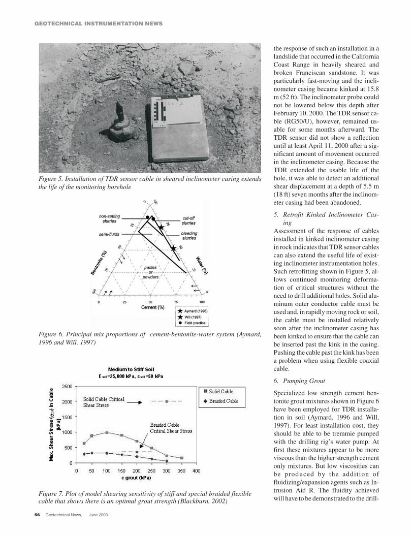
the response of such an installation in alandslide that occurred in the CaliforniaCoast Range in heavily sheared andbroken Franciscan sandstone. It wasparticularly fast-moving and the incli-nometer casing became kinked at 15.8m (52 ft). The inclinometer probe couldnot be lowered below this depth afterFebruary 10, 2000. The TDR sensor ca-ble (RG50/U), however, remained us-able for some months afterward. TheTDR sensor did not show a reflectionuntil at least April 11, 2000 after a sig-nificant amount of movement occurredin the inclinometer casing. Because theTDR extended the usable life of thehole, it was able to detect an additionalshear displacement at a depth of 5.5 m(18 ft) seven months after the inclinom-eter casing had been abandoned.
5. Retrofit Kinked Inclinometer Cas-ing
Assessment of the response of cablesinstalled in kinked inclinometer casingin rock indicates that TDR sensor cablescan also extend the useful life of exist-ing inclinometer instrumentation holes.Such retrofitting shown in Figure 5, al-lows continued monitoring deforma-tion of critical structures without theneed to drill additional holes. Solid alu-minum outer conductor cable must beused and, in rapidly moving rock or soil,the cable must be installed relativelysoon after the inclinometer casing hasbeen kinked to ensure that the cable canbe inserted past the kink in the casing.Pushing the cable past the kink has beena problem when using flexible coaxialcable.
6. Pumping Grout
Specialized low strength cement ben-tonite grout mixtures shown in Figure 6have been employed for TDR installa-tion in soil (Aymard, 1996 and Will,1997). For least installation cost, theyshould be able to be tremmie pumpedwith the drilling rig’s water pump. Atfirst these mixtures appear to be moreviscous than the higher strength cementonly mixtures. But low viscosities canbe produced by the addition offluidizing/expansion agents such as In-trusion Aid R. The fluidity achievedwill have to be demonstrated to the drill-
GEOTECHNICAL INSTRUMENTATION NEWS
Geotechnical News, June 2003
Figure 5. Installation of TDR sensor cable in sheared inclinometer casing extendsthe life of the monitoring borehole
Figure 6. Principal mix proportions of cement-bentonite-water system (Aymard,1996 and Will, 1997)
Figure 7. Plot of model shearing sensitivity of stiff and special braided flexiblecable that shows there is an optimal grout strength (Blackburn, 2002)

ing crew, who may not wish to pump itfor fear of blocking their pump. A sepa-rate grout pump can also be used for ca-ble installation. Refer to Mikkelsen(2002) for an excellent discussion ofgrout mixing procedures and strength,as well as field crews errors in usinggrout mixes with high water content andbleeding.
7. Installation Using Hollow StemAugers
Installation with hollow stem augersmay lead to degradation of responsethrough two mechanisms. First, groutslumps into the large void left as the au-ger is extracted. Unless a sufficient headof grout is maintained in the auger as itis extracted, voids will exist between thecable and hole walls. Extra grout at ahigher head should be available to fillthe large annulus created as the auger isextracted. Secondly, extraction of theauger will disturb the soil around theTDR sensor cable (Dussud, 2002).
8. Soil-Grout-Cable Interaction
Use of TDR sensor cables in soft soil re-
quires special cement-bentonite groutmixes with prehydrated bentonite andfluidizing agent which should be care-
GEOTECHNICAL INSTRUMENTATION NEWS
Geotechnical News, June 2003
Figure 8. View of the sealed end tip of a flexible TDR sensorcable also fitted with a plastic cone to catch the PVC grouttube for insertion
Figure 9. Insertion of TDR sensor cable in CPT rods after at-taching special disposable tip
Figure 10. View of an integrated DAS comprising (from the left) a TDR 100pulser, a 12V battery, a CR10X datalogger and communication equipment (phonemodem and cellular phone)

fully designed to match the soil proper-ties. The grout must be stiff enough tokink the cable, but not so stiff (strong)that it resists localized soil shearing.Special low loss, flexible cables will al-low use of low strength grouts in softsoils. Model results in Figure 7 showthat shearing sensitivity of stiff and spe-cial flexible grouted coaxial cable is op-timal at a ratio of grout to soil strengthof 1 to 5 (Blackburn, 2002). Shearstresses in the more compliant braidedcable are closer to the critical value,which is the model shear stress associ-ated with the first appearance of a TDRvoltage reflection. More research willbe needed to determine optimal groutmixtures.
9. Sealing and Insertion of Cables
Appropriate techniques for cable inser-tion are dependent upon cable stiffness.Flexible cables have been inserted byattaching to the cable tip a plastic coneas shown in Figure 8 in order to catchthe stiff flush coupled PVC grout pipeas it is pushed in the hole. Alternativelythe bottom of stiff solid aluminum co-axial cables can be fitted with a me-ter-long section of PVC or steel pipe(acting as a stiffener/strengthener) andthen pushed down the hole. Before in-sertion, the bottom end of the TDR co-axial cable must be sealed to prevent in-trusion of water between the inner andouter conductor.
10. Installation using CPT Rig
As shown in Figure 9, 12.5 mm diame-ter FLC12-50J cables have been in-
ser ted in soft soi l with conepenetrometer equipment (CPT). Afterdetermination of stratigraphy the CPTrods are reinserted and the cable placedinside. A special tip is machined for thecable and left in place as the rods arewithdrawn. The hole is grouted whileextracting the rods. Such technique wasused in a landslide in Orange County,California to install a 25 meter deep ca-ble. There are many situations in softsoils, such as investigation of levee sta-bility, where the CPT method workswell.
11. Crimping and Connectors Details
Miscellaneous details include: 1) mak-ing distance-calibration crimps whilelowering the cable to avoid accidentalkinking at the crimp during installationand 2) ensuring top-of-hole connectorsare moisture-proofed and placed in alocked protective cover (Dussud,2002).
TOP 8 “TDR Instrumentation”Lessons
1. Integration of Data AcquisitionComponents
PC based data acquisition systems(DAS) with off-the-shelf componentsshould be avoided because of integra-tion and reliability problems. Reliable,rugged systems should be employedsuch as those offered by Campbell Sci-entific Inc. combining a TDR 100pulser and a CR10X datalogger. Theseinstruments, shown in Figure 10, alsohave relatively low power consumption,
which is an advantage for remote sitemonitoring.
2. Alarm Call Capability
Automated surveillance of remote sitesfrom a central polling computer (pas-sive monitoring) as well as callbackalarm notification from remote sites(active monitoring) has been success-ful ly implemented with TDR(O’Connor et al, 2002). Figure 11shows a typical DAS equipped with analarm autodialer.
3. Web-based data Display
Autonomous posting of TDR wave-forms over the internet on a daily basishas been successfully implemented formonitoring of deformation of multiplecables at multiple locations. Examplescan be seen at http://www.iti.northwest-ern.edu/tdr (Kosnik and Kotowski,2002).
4. Telemetry
Hard-wired phone and power lines arepreferable at sites that involve real timemonitoring and callback alarms. How-ever, several truly remote operations arebeing operated using cell phone, radiocommunication and solar power(Dussud, 2002).
5. Low-loss Lead Cable
Long lead cables should be of the lowloss, 75 Ohm F11 variety. The often em-ployed, standard, 50 Ohm, RGU con-necting cables should be kept as short aspossible (<50 m) to minimize attenua-tion and noise. Such problems have
GEOTECHNICAL INSTRUMENTATION NEWS
Geotechnical News, June 2003
Figure 11. Remote TDR monitoring system with alarmautodialer
Figure 12. Protective enclosure for connection between asensor and a connecting cable

arisen with RG58 and RG59 lead ca-bles.
6. Multisensor Monitoring Systems
Integrated multiparameter monitoringsystems have been implemented withtiltmeters and TDR sensor cables at re-mote datalogger-controlled installa-tions. These have involved monitoringof bridge pier deformation from scourand from mining induced subsidencealong highways.
7. Connector Accessibility
Connections between different cables(i.e. transmission and transducer ca-bles) are a weak link and should bemade as robust and water proof as pos-sible. N-type connectors are recom-mended, but F-type have also beenused. They should also be accessible formaintenance as shown in Figure 12.
8. Digital Data Format
If cables are interrogated manually witha Tektronix 1502 cable tester, it shouldbe equipped with a SP232 module to ac-quire digital records for display, analy-sis and quantification of TDR reflec-tions.
AcknowledgementsDirect financial support for develop-ment of TDR technology has been pro-vided by the U.S. Department of Trans-portat ion funded InfrastructureTechnology Institute of NorthwesternUniversity from 1993 to the present andthe Civil Mechanical Systems Divisionof the National Science Foundation be-tween 1995 and 2001. The authors arealso indebted to the many other individ-uals and organizations that also havesupported this development but are toonumerous to mention by name.
ReferencesAymard, N. (1996) “Low Strength
Grouts for Embedding TDR Cablesin Soil,” M.S Thesis, Department ofCivil and Environmental Engineer-ing, Northwestern University,Evanston, IL USA, December.
Blackburn, J.T. (2002) Finite ElementAnalysis of TDR Sensor Ca-ble-Grout-Soil Mass Interaction
During Localized Shearing, M.SThesis, Department of Civil and En-vironmental Engineering, North-western University, Evanston, IL,USA, April.
Cole, R. G. (1999) “Compliant TDRsensor cable Grout Composites toMeasure Localized Soil Deforma-tion” M.S. Thesis, Department ofCivil and Environmental Engineer-ing, Northwestern University,Evanston, IL, USA, December.
Dowding, C.H. , Su, M.B. andO’Connor, K.M. (1988) “Principlesof Time Domain Reflectometry Ap-plied to Measurement of Rock MassDeformation,” Int. Journal of RockMechanics and Mineral Science,Vol. 25, No.5, pp. 287-297.
Dowding, C.H. and O’Connor, K.M.(2000) “Comparison of TDR andSlope Inclinometers for Slope Moni-toring,” ASCE Geotechnical SpecialTechnical Publication, No. 106 pp80-90.
Dussud, M. L. (2002) “Case Historiesand Field Techniques for TDR Mon-itoring of Soil Deformation,” M.SThesis, Department of Civil and en-vironmental Engineering, North-western University, Evanston, IL,USA, Dec.
Kosnik D. and Kotowski M. (2002) “In-frastructure Remote MonitoringSoftware,” Infrastructure Technol-ogy Institute, Internal Report,Northwestern University, Evanston,IL.
Mikkelsen, P.E. (2002) “Cement-Ben-tonite Grout Backfill for BoreholeInstruments,” Geotechnical News,December pp. 38-42.
O’Connor, K.M. and C.H. Dowding(1999) GeoMeasurements by Puls-ing TDR Cables and Probes. CRCPress, Boca Raton, 420p.
O’Connor, K.M., Peterson, D.E. andLord E.R. (1995) “Development of aHighwall Monitoring System UsingTime Domain Reflectometry,” Pro-ceedings, 35th U.S. Symposium onRock Mechanics, Reno, Nevada,June, pp.79-84.
O’Connor, K.M., R. Ruegsegger, andK. Beach (2002) “Real Time Moni-
toring of Subsidence Along Inter-state I-77, Summit County, Ohio”ITGAUM 4th Biennial AbandonedUnderground Mine Workshop, Dav-enport, Iowa,http://www.fhwa.dot.gov///mine/oconnor.htm
O’Connor, K.M. and Wade, L.V.(1994), “Applications of Time Do-main Reflectometry in the MiningIndustry,” Proceedings of the Sym-posium and Workshop on TDR inEnvironmental, Infrastructure andMining Applications, NorthwesternUniversity, Evanston, IL, USA, Sep-tember, pp. 494-506.
Pierce, C. E. (1998) “A Compliant Co-axial Cable-Grout Composite forTime Domain Reflectometry Mea-surements of Localized Soil Defor-mation,” Ph.D. Thesis, Departmentof Civil and Environmental Engi-neering, Northwestern University,Evanston, IL, USA, December.
Will, D. (1997), “Cement BentoniteGrouts Compatible with CompliantTDR Cables,” M.S Thesis, Depart-ment of Civil and Environmental En-gineering, Northwestern University,Evanston, IL, USA, December.
Charles H. Dowding and Matthieu L.Dussud, Professor and Graduate Stu-dent: Department of Civil & Environ-mental Engineering, NorthwesternUniversity, Evanston, IL 60208,Tel: 847-491-4338,Fax: 847-491-4338,email: [email protected];[email protected]
William F. Kane, President, KaneGeotech, Inc., PO Box 7526, Stockton,CA 95267-0526, Tel: 209-472-1822,Fax: 209-472-0802,email [email protected]
Kevin M. O'Connor, President ,GeoTDR, Inc. 720 Greencrest Drive,Westerville, OH 43081-4902,Tel: 614-895-1400,Fax: 614-895-1171,email: [email protected]
GEOTECHNICAL INSTRUMENTATION NEWS
Geotechnical News, June 2003