CAD model simplification using a removing details and ...€¦ · CAD model simplification using a...
10
Journal of Mechanical Science and Technology 26 (11) (2012) 3539~3548 www.springerlink.com/content/1738-494x DOI 10.1007/s12206-012-0869-6 CAD model simplification using a removing details and merging faces technique for a FEM simulation † Hamdi Mounir, Aifaoui Nizar * and Benamara Abdelmajid LGM, ENIM, University of Monastir, Av Ibn Eljazzar 5019 Monastir, Tunisia (Manuscript Received December 1, 2011; Revised May 13, 2012; Accepted June 15, 2012) ---------------------------------------------------------------------------------------------------------------------------------------------------------------------------------------------------------------------------------------------------------------------------------------------- Abstract The simulation process is currently used in the design and dimensioning of mechanical parts. With the progress of computer materials, the finite elements method (FEM) becomes the most used approach in the simulation of mechanical behaviour. The simulation process needs multiple Design-FEM loops. In order to accelerate those analysis loops, an adaptation of computer aided design (CAD) model is necessary. The adaptation step consists in the simplification of the CAD model geometry by eliminating details (holes, chamfers, fillet, etc.) and faces. In this paper, a novel technique of simplification of the CAD geometry is developed. This technique is a hybrid method based on a combination of the elimination details and merging faces. The merging of faces is based on the energetic method. With this approach, the computing time is reduced by the elimination of geometric details which do not boundary conditions. An implementation of the proposed algorithm on the Open Cascade platform is also presented. The results of the developed method are compared with a previous publication. The reduction of the computing time and the amelioration of the result precision highlight the efficiency of the presented method. Keywords: CAD model; Analysis model; Simplification model; Simulation; Hybrid method ---------------------------------------------------------------------------------------------------------------------------------------------------------------------------------------------------------------------------------------------------------------------------------------------- 1. Introduction For a long time, design and mechanical analysis were con- sidered two independent activities. Our research tasks aim at the improvement of the CAD models preparation's phase even before starting the mesh stage. The preparation of a CAD model consists in idealizing or cleaning the geometry by eliminating details (holes, chamfer, fillet, etc), considered superfluous for the simulation [1]. Then, these details are zones where the mesh will be automatically refined, which will generate a very important computing time without bring- ing more precision to the results of simulation. The simplified models are used in many simulation do- mains: for dynamic analysis of satellite [2]; modeling flow conditions in the tunnel [3]; vibration of penetration beam- plate coupled structures [4]; aircraft icing simulation [5]; structural optimization of an automobile transmission [6] and for analyze the difference of 3-D CAD model by feature ex- traction [7], etc. The generation of an analysis model using the CAD geome- try is based on some analysis assumptions. These assumptions are related to the material behavior, solicitations and the ge- ometry definition of the part. In the bibliography [8-10], sev- eral research tasks were interested in the CAD geometry adap- tation problems to analysis models dedicated to the mechani- cal analysis by the finite elements method. Thakur et al. [11] studied existing model simplification techniques that are useful from the physics based simulation and classified them broadly into four main categories based upon the type of simplification operators used in the respec- tive techniques, i.e. surface entity, volumetric entity, explicit feature and dimensional reduction. Dabke et al. [12] uses an identification method of entities (features) to carry out the adaptation and the simplification of geometrical models by suppression, in CSG models. This technique is based on expert system implementing heuristic rules resulting from the analyst experience. Belaziz et al. [13] proposes an adaptation method of geome- try based on the features’ recognition approach. In this ap- proach, the recognition is carried out by a morphological analysis of the CAD geometry, that’s why this method is more flexible than the Dabke’s method. The adapted and idealized geometry is generated by the removal of some form features considered as being non characteristic for the considered me- chanical analysis. Sheffer et al. [14] develops a suppression procedure of de- tails and "cleaning" of the CAD geometry using the principles * Corresponding author. Tel.: +216 98 901 839, Fax.: +216 73 500 514 E-mail address: [email protected] † Recommended by Associate Editor Ki-Hoon Shin © KSME & Springer 2012
Transcript of CAD model simplification using a removing details and ...€¦ · CAD model simplification using a...

Journal of Mechanical Science and Technology 26 (11) (2012) 3539~3548
www.springerlink.com/content/1738-494x
DOI 10.1007/s12206-012-0869-6
CAD model simplification using a removing details and merging faces technique
for a FEM simulation†
Hamdi Mounir, Aifaoui Nizar* and Benamara Abdelmajid
LGM, ENIM, University of Monastir, Av Ibn Eljazzar 5019 Monastir, Tunisia
(Manuscript Received December 1, 2011; Revised May 13, 2012; Accepted June 15, 2012)
----------------------------------------------------------------------------------------------------------------------------------------------------------------------------------------------------------------------------------------------------------------------------------------------
Abstract
The simulation process is currently used in the design and dimensioning of mechanical parts. With the progress of computer materials,
the finite elements method (FEM) becomes the most used approach in the simulation of mechanical behaviour. The simulation process
needs multiple Design-FEM loops. In order to accelerate those analysis loops, an adaptation of computer aided design (CAD) model is
necessary. The adaptation step consists in the simplification of the CAD model geometry by eliminating details (holes, chamfers, fillet,
etc.) and faces. In this paper, a novel technique of simplification of the CAD geometry is developed. This technique is a hybrid method
based on a combination of the elimination details and merging faces. The merging of faces is based on the energetic method. With this
approach, the computing time is reduced by the elimination of geometric details which do not boundary conditions. An implementation
of the proposed algorithm on the Open Cascade platform is also presented. The results of the developed method are compared with a
previous publication. The reduction of the computing time and the amelioration of the result precision highlight the efficiency of the
presented method.
Keywords: CAD model; Analysis model; Simplification model; Simulation; Hybrid method
----------------------------------------------------------------------------------------------------------------------------------------------------------------------------------------------------------------------------------------------------------------------------------------------
1. Introduction
For a long time, design and mechanical analysis were con-
sidered two independent activities. Our research tasks aim at
the improvement of the CAD models preparation's phase even
before starting the mesh stage. The preparation of a CAD
model consists in idealizing or cleaning the geometry by
eliminating details (holes, chamfer, fillet, etc), considered
superfluous for the simulation [1]. Then, these details are
zones where the mesh will be automatically refined, which
will generate a very important computing time without bring-
ing more precision to the results of simulation.
The simplified models are used in many simulation do-
mains: for dynamic analysis of satellite [2]; modeling flow
conditions in the tunnel [3]; vibration of penetration beam-
plate coupled structures [4]; aircraft icing simulation [5];
structural optimization of an automobile transmission [6] and
for analyze the difference of 3-D CAD model by feature ex-
traction [7], etc.
The generation of an analysis model using the CAD geome-
try is based on some analysis assumptions. These assumptions
are related to the material behavior, solicitations and the ge-
ometry definition of the part. In the bibliography [8-10], sev-
eral research tasks were interested in the CAD geometry adap-
tation problems to analysis models dedicated to the mechani-
cal analysis by the finite elements method.
Thakur et al. [11] studied existing model simplification
techniques that are useful from the physics based simulation
and classified them broadly into four main categories based
upon the type of simplification operators used in the respec-
tive techniques, i.e. surface entity, volumetric entity, explicit
feature and dimensional reduction.
Dabke et al. [12] uses an identification method of entities
(features) to carry out the adaptation and the simplification of
geometrical models by suppression, in CSG models. This
technique is based on expert system implementing heuristic
rules resulting from the analyst experience.
Belaziz et al. [13] proposes an adaptation method of geome-
try based on the features’ recognition approach. In this ap-
proach, the recognition is carried out by a morphological
analysis of the CAD geometry, that’s why this method is more
flexible than the Dabke’s method. The adapted and idealized
geometry is generated by the removal of some form features
considered as being non characteristic for the considered me-
chanical analysis.
Sheffer et al. [14] develops a suppression procedure of de-
tails and "cleaning" of the CAD geometry using the principles
*Corresponding author. Tel.: +216 98 901 839, Fax.: +216 73 500 514
E-mail address: [email protected] † Recommended by Associate Editor Ki-Hoon Shin
© KSME & Springer 2012
3540 H. Mounir et al. / Journal of Mechanical Science and Technology 26 (11) (2012) 3539~3548
of virtual topology. This topology is based on regrouping the
faces constituting the B-Rep model in areas admitting the
same characteristics of curve and dimension.
Armstrong et al. [15] and Donaghy [16] use the Medial
Axis Transform (MAT) to carry out the adaptation and the
simplification of B-Rep geometry. The MAT method builds
the skeleton of a geometrical representation in order to obtain
the median axis. A circle with a variable diameter sweeps the
interior of the structure remaining constantly in contact, in at
least 2 points with the structure. The skeleton is obtained by
building the places of the center of the circle. For a 3D geome-
try, the circle is replaced by a sphere and the places of its cen-
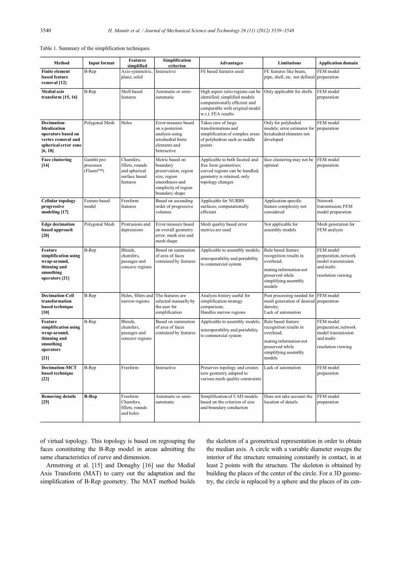
Table 1. Summary of the simplification techniques.
Method Input formatFeatures
simplified
Simplification
criterionAdvantages Limitations Application domain
Finite element
based feature
removal [12]
B-Rep Axis-symmetric,
plane, solid
Interactive FE based features used FE features like beam,
pipe, shell, etc. not defined
FEM model
preparation
Medial axis
transform [15, 16]
B-Rep Shell based
features
Automatic or semi-
automatic
High aspect ratio regions can be
identified; simplified models
computationally efficient and
comparable with original model
w.r.t. FEA results
Only applicable for shells FEM model
preparation
Decimation-
Idealization
operators based on
vertex removal and
spherical error zone
[6, 18]
Polygonal Mesh Holes Error measure based
on a posteriori
analysis using
tetrahedral finite
elements and
Interactive
Takes care of large
transformations and
simplification of complex areas
of polyhedron such as saddle
points
Only for polyhedral
models; error estimator for
hexahedral elements not
developed
FEM model
preparation
Face clustering
[14]
Gambit pre-
processor
(Fluent™)
Chamfers,
fillets, rounds
and spherical
surface based
features
Metric based on
boundary
preservation, region
size, region
smoothness and
simplicity of region
boundary shape
Applicable to both faceted and
free form geometries;
curved regions can be handled;
geometry is retained, only
topology changes
face clustering may not be
optimal
FEM model
preparation
Cellular topology
progressive
modeling [17]
Feature based
model
Freeform
features
Based on ascending
order of progressive
volumes
Applicable for NURBS
surfaces; computationally
efficient
Application specific
feature complexity not
considered
Network
transmission; FEM
model preparation
Edge decimation
based approach
[20]
Polygonal Mesh Protrusions and
depressions
Error measure based
on overall geometry
error, mesh size and
mesh shape
Mesh quality based error
metrics are used
Not applicable for
assembly models
Mesh generation for
FEM analysis
Feature
simplification using
wrap-around,
thinning and
smoothing
operators [21]
B-Rep Blends,
chamfers,
passages and
concave regions
Based on summation
of area of faces
contained by features
Applicable to assembly models;
interoperability and portability
to commercial system
Rule based feature
recognition results in
overhead;
mating information not
preserved while
simplifying assembly
models
FEM model
preparation, network
model transmission
and multi-
resolution viewing
Decimation-Cell
transformation
based technique
[10]
B-Rep Holes, fillets and
narrow regions
The features are
selected manually by
the user for
simplification
Analysis history useful for
simplification strategy
comparison;
Handles narrow regions
Post processing needed for
mesh generation of desired
density;
Lack of automation
FEM model
preparation
Feature
simplification using
wrap-around,
thinning and
smoothing
operators
[21]
B-Rep Blends,
chamfers,
passages and
concave regions
Based on summation
of area of faces
contained by features
Applicable to assembly models;
interoperability and portability
to commercial system
Rule based feature
recognition results in
overhead;
mating information not
preserved while
simplifying assembly
models
FEM model
preparation, network
model transmission
and multi-
resolution viewing
Decimation-MCT
based technique
[22]
B-Rep Freeform Interactive Preserves topology and creates
new geometry adapted to
various mesh quality constraints
Lack of automation FEM model
preparation
Removing details
[25]
B-Rep Freeform
Chamfers,
fillets, rounds
and holes
Automatic or semi-
automatic
Simplification of CAD models
based on the criterion of size
and boundary conduction
Does not take account the
location of details
FEM model
preparation
H. Mounir et al. / Journal of Mechanical Science and Technology 26 (11) (2012) 3539~3548 3541
ter represent a surface. This skeleton is then used to carry out
an analysis of the geometry in order to characterize the set of
details which composes the 3D geometry. Then, the geometri-
cal representation is adapted or idealized by the means of the
Euler operators.
Lee et al. [17] present a method to generate progressive
solid models (PSM) from feature-based models using a cellu-
lar topology-based approach. Here, cellular topology is used to
generate the PSM, and then the surface entity based operators
are developed to simplify the model. The main concept in this
paper is to start with a feature based model as input and gener-
ate a sequence of solid models representing the underlying
object with various levels of details. The intended purpose of
the PSM is to stream models over a network efficiently.
Fine et al. [18] introduced simplification operators for the
Finite Element Analysis. The operators are based on the ver-
tex removal and spherical error zone concept.
Mobley et al. [19] reported an object-oriented approach to
develop surface-based disfeaturing operators to suppress small
features for the FEA model preparation.
Date et al. [20] reported vertex and an edge collapse-based
technique for the mesh model simplification and refinement.
They defined three metrics based on the overall geometry
error, face size and face shape. The metrics are evaluated
for the edges to determine their priority index for simplifica-
tion.
Kim et al. [21] reported a system for a multi-resolution fea-
ture simplification using three operators, namely wrap-around,
smooth out and thinning. The method is applied to the finite
element model preparation and network transmission multi-
resolution modeling. The features are first recognized using
rule-based techniques and then various operators are applied
to suppress them. In the case of the wraparound operator, the
model is considered to be wrapped by a thin plastic cover. The
parts of the model hidden by the cover are considered for sim-
plification or removal.
Foucault et al. [22] reported a topology simplification tech-
nique for the finite element mesh generation. The authors have
developed a Mesh Constraint Topology (MCT) based on the
model simplification scheme to address the sharp corner
matching requirements. MCT entities are defined as compos-
ite topological entities created to suit the mesh generation
requirements stated before. The MC face is a poly-surface,
defined as the union of Riemannian surfaces constituting the
reference model. The MC edge is a poly-curve, defined as a
union of Riemannian curves constituting the reference model.
Woo et al. [23] presented a method that is mainly focused
on the mechanical parts that will be created by machining.
That is, the most simplified result of a solid model will be the
solid model of stock material. Independently of user-specified
design features, this method simplifies the solid model by
removing the detailed geometry by using these subtractive
features. If a solid model is not appropriate to be represented
in terms of machining features, unnatural simplification may
happen for the solid model.
Hamdi et al. [24], CAD/CAE interoperability, an automatic
generation of Analysis Model based on the simplification of
CAD geometry is implemented using the Open Cascade plat-
form. In this work, the simply size criteria is integrated, and in
Ref. [25], a simplification algorithm of CAD models for a
simulation by the finite element method is presented. The
algorithm proposed consists in reading the B-rep model of the
CAD geometry in order to identify, and then remove the de-
tails considered to be superfluous for the mechanical analysis,
using two criteria of size and boundary condition. In this work,
the creation tree of CAD model (CSG) is not taken into ac-
count not only because it is not unique but also it is easily lost
by a simple CAD model transfer between the different work-
ing tools. Table 1 summarizes and compares the simplification
techniques.
Based on the bibliography previously presented, the contri-
bution of this works is positioned in the: “model simplification
technique for surface entity based operators” [11].
The objective of this paper is to propose an original method
which can guide the designer in the phase of the CAD model's
preparation for a simulation by the finite elements method
(FEM). According to the suggested approach, the elimination
of the details is based on a representation by Iso-zones ena-
bling the designer to visualize the details which are candidates
for elimination or fusion if they are positioned in the stress
concentration zone.
This paper can be divided in to three sections. The first one
has presented a state of the art on the principal techniques used
to eliminate details from the CAD geometry. In the second
section, the proposed method of simplification is proposed. In
order to highlight the efficiency in the reduction of the design
time and the cost of the product, an example of a mechanical
part has been studied using the proposed approach, and pre-
sented in the third section.
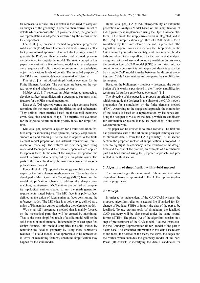
2. Algorithm of simplification with hybrid method
The proposed algorithm composed of three principal inter-
dependent phases is represented in Fig. 1. Each phase implies
overlapping stages.
2.1 Principle
In order to be independent of the CAD/CAM systems, the
proposed algorithm relies on a neutral file (Standard for Ex-
change of Product: STEP) to import the data of the part to be
idealized. To use various tools of simulation, the idealized
CAD geometry will be also stored under the same neutral
format (STEP). The phase (A) of the algorithm consists in a
step of pre-treatment of the CAD model. It allows restructur-
ing the Boundary Representation (B-rep) model of the part to
a data base. The structured information in this data base relates
to the faces, the normal of the faces, the wires, the edges and
the vertex which includes the geometry model of the part.
Phase (B) consists in identifying the details candidates for
3542 H. Mounir et al. / Journal of Mechanical Science and Technology 26 (11) (2012) 3539~3548
simplification. That implies the implementation of algorithms
of identification based on criteria (forms, sizes, function, posi-
tion…). The result of this phase is a representation of Iso-
zones targets for simplification. These Iso-zones are entities
(edges, faces) coloured according to the specificity of each
face. This original vision enables the designer to visualize the
least influential zones (high order of criticality) on the compu-
tation results, giving him the possibility either to inter-actively
eliminate the entities which have a high order of criticality, or
to apply the automatic algorithms of simplification. The stage
(7) consists in the creation of Boundary Conditions (BC) de-
limited box. And the phase (C) allows the reconstruction of
the simplified model. Stage (9) consists in removing the iden-
tified details, if they are outside the BC delimited box, then in
rebuilding the geometric model after suppression. Stage (10)
consists in the fusion of the identified details with the adjacent
faces if they are inside the Box (the details represent the con-
centrator’s stress). The result of stage (12) is an idealized
CAD model whose elementary topology is validated in stage
(13). At the exit of the algorithm, the designer has at his dis-
posal an idealized model saved in the STEP format for a simu-
lation by finite elements.
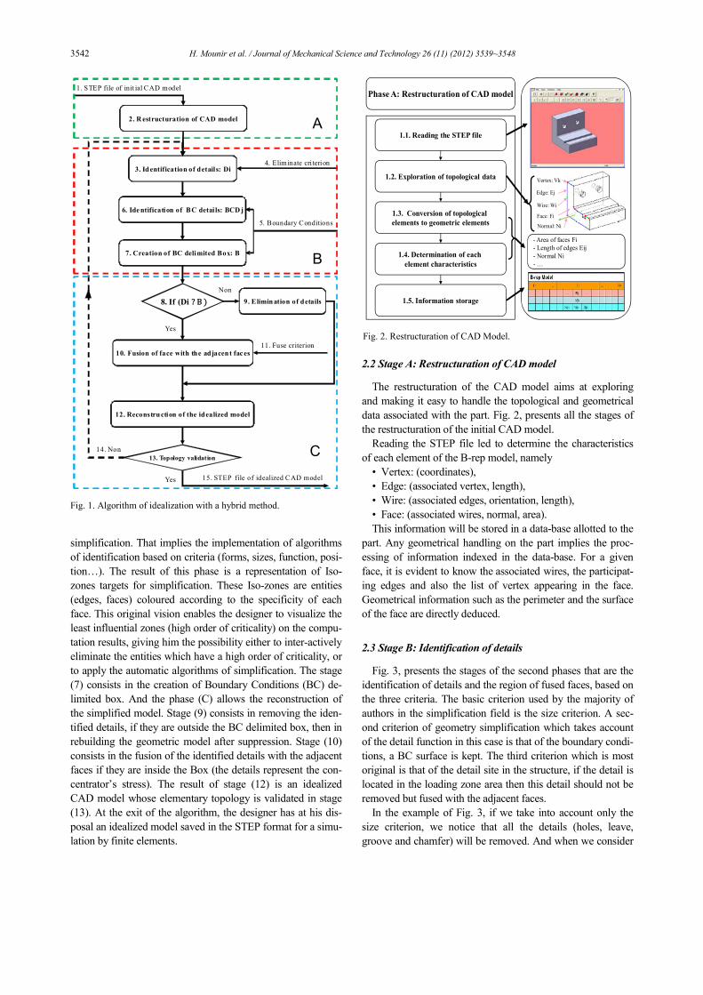
2.2 Stage A: Restructuration of CAD model
The restructuration of the CAD model aims at exploring
and making it easy to handle the topological and geometrical
data associated with the part. Fig. 2, presents all the stages of
the restructuration of the initial CAD model.
Reading the STEP file led to determine the characteristics
of each element of the B-rep model, namely
• Vertex: (coordinates),
• Edge: (associated vertex, length),
• Wire: (associated edges, orientation, length),
• Face: (associated wires, normal, area).
This information will be stored in a data-base allotted to the
part. Any geometrical handling on the part implies the proc-
essing of information indexed in the data-base. For a given
face, it is evident to know the associated wires, the participat-
ing edges and also the list of vertex appearing in the face.
Geometrical information such as the perimeter and the surface
of the face are directly deduced.
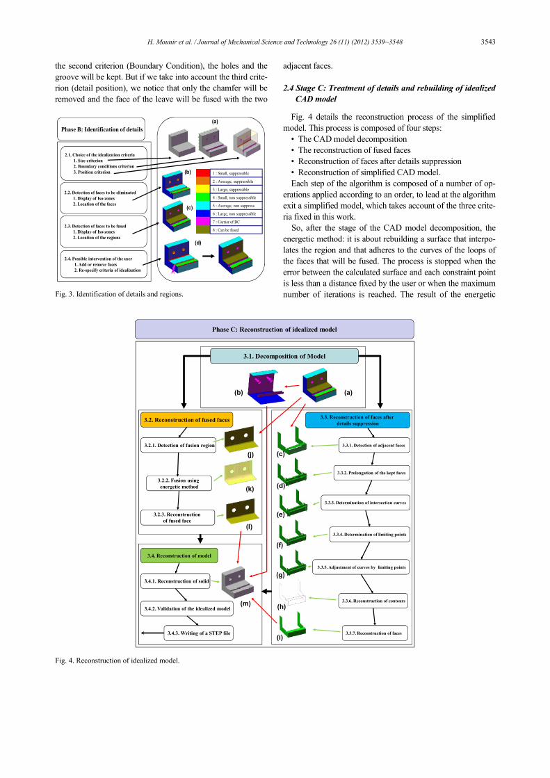
2.3 Stage B: Identification of details
Fig. 3, presents the stages of the second phases that are the
identification of details and the region of fused faces, based on
the three criteria. The basic criterion used by the majority of
authors in the simplification field is the size criterion. A sec-
ond criterion of geometry simplification which takes account
of the detail function in this case is that of the boundary condi-
tions, a BC surface is kept. The third criterion which is most
original is that of the detail site in the structure, if the detail is
located in the loading zone area then this detail should not be
removed but fused with the adjacent faces.
In the example of Fig. 3, if we take into account only the
size criterion, we notice that all the details (holes, leave,
groove and chamfer) will be removed. And when we consider
2. Restructuration of CAD model
3. Identification of details: Di
12. Reconstruction of the idealized model
15. STEP file of idealized CAD model
1. STEP file of init ial CAD model
13. Topology validation
4. Eliminate cri terion
11. Fuse criterion
9. Elimination of details
5. Boundary Conditions
7. Creation of BC delimited Box: B
8. If (Di ? B )
10. Fusion of face with the adjacent fac es
Non
14. Non
Yes
Yes
6. Identification of BC detai ls: BCD j
A
B
C
Fig. 1. Algorithm of idealization with a hybrid method.
Phase A: Restructuration of CAD model
1.1. Reading the STEP file
1.2. Exploration of topological data
1.3. Conversion of topological
elements to geometric elements
1.4. Determination of each
element characteristics
1.5. Information storage
Face: Fi
Vertex: Vk
Wire: Wi
Edge: Ej
- Area of faces Fi
- Length of edges Eij
- Normal Ni
- …
Normal: Ni
Fig. 2. Restructuration of CAD Model.
H. Mounir et al. / Journal of Mechanical Science and Technology 26 (11) (2012) 3539~3548 3543
the second criterion (Boundary Condition), the holes and the
groove will be kept. But if we take into account the third crite-
rion (detail position), we notice that only the chamfer will be
removed and the face of the leave will be fused with the two
adjacent faces.
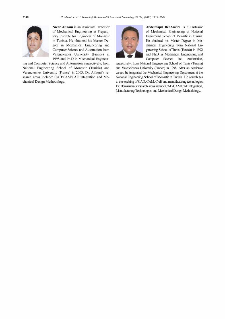
2.4 Stage C: Treatment of details and rebuilding of idealized
CAD model
Fig. 4 details the reconstruction process of the simplified
model. This process is composed of four steps:
• The CAD model decomposition
• The reconstruction of fused faces
• Reconstruction of faces after details suppression
• Reconstruction of simplified CAD model.
Each step of the algorithm is composed of a number of op-
erations applied according to an order, to lead at the algorithm
exit a simplified model, which takes account of the three crite-
ria fixed in this work.
So, after the stage of the CAD model decomposition, the
energetic method: it is about rebuilding a surface that interpo-
lates the region and that adheres to the curves of the loops of
the faces that will be fused. The process is stopped when the
error between the calculated surface and each constraint point
is less than a distance fixed by the user or when the maximum
number of iterations is reached. The result of the energetic
Phase B: Identification of details
2.1. Choice of the idealization criteria
1. Size criterion
2. Boundary conditions criterion
3. Position criterion
2.2. Detection of faces to be eliminated
1. Display of Iso-zones
2. Location of the faces
2.4. Possible intervention of the user
1. Add or remove faces
2. Re-specify criteria of idealization
(a)
(b)
(c)
1 : Small, suppressible
2 : Average, suppressible
3 : Large, suppressible
4 : Small, non suppressible
5 : Average, non suppress
6 : Large, non suppressible
7 : Carrier of BC
8 : Can be fused2.3. Detection of faces to be fused
1. Display of Iso-zones
2. Location of the regions
(d)
Fig. 3. Identification of details and regions.
(d)
Phase C: Reconstruction of idealized model
3.3.1. Detection of adjacent faces
3.3.2. Prolongation of the kept faces
3.3.3. Determination of intersection curves
3.3.4. Determination of limiting points
3.3.5. Adjustment of curves by limiting points
3.3.6. Reconstruction of contours
3.3.7. Reconstruction of faces
3.4.1. Reconstruction of solid
3.4.2. Validation of the idealized model
3.4.3. Writing of a STEP file
(e)
(f)
(g)
3.3. Reconstruction of faces after
details suppression3.2. Reconstruction of fused faces
3.2.1. Detection of fusion region
3.2.2. Fusion using
energetic method
3.2.3. Reconstruction
of fused face
(c)
(k)
(j)
(l)
3.1. Decomposition of Model
(b) (a)
3.4. Reconstruction of model
(h)(m)
(i)
Fig. 4. Reconstruction of idealized model.

3544 H. Mounir et al. / Journal of Mechanical Science and Technology 26 (11) (2012) 3539~3548
method is a NURBS surface.
As for the procedure of CAD model’s rebuilding after the
elimination of faces, it consists, firstly, in detecting the adja-
cent faces to the removed entities. The detection of adjacent
faces is based on the database part processed in the first stage.
Secondly, it consists in prolonging these faces in all directions.
That will lead to detecting intersections curves due to the pro-
longation of faces. The vertex ‘limit’ will be determined from
curves, then the edges will be delimited by the vertex. The
CAD model is regenerated by rebuilding faces associated to
new wires. A new database of the idealized part is thus com-
pleted. The designer has the B-rep model of the part before
and after simplification. A file ‘STEP’ is finally generated in
order to use the idealized CAD model by an analysis tool.
The proposed algorithm of simplification is adjudicated
universal because it is based only on the B-rep model of the
CAD geometry. This algorithm is completely independent of
the CAD geometry creation tree, because of the non-
uniqueness of this tree. In addition, the CAD model, once
exported, loses any information in its manner of creation.
3. Data-processing implementation and validation on
example
3.1 Data-processing implementation
The data-processing implementation of the simplification
algorithm was carried out on a development's platform: 'Open
Cascade'. Open Cascade is an environment dedicated to the
development of 3D applications of CAD-CAM multi-
platforms. This platform is available and free on Internet. It is
based on a bookstore of C++ classes and tools developed and
available in open source.
3.2 Example of validation
In this section, one example of validation will allow validat-
ing the principal functionalities of the simplification algorithm.
Fig. 5 presents a stair climber machine. The part “support”
was selected because they have a broad variety of mechanical
parts in terms of its forms, the boundary conditions, and also
the details which they contain. The validation example is pre-
sented in Ref. [25]. The CAD model simplified using the hy-
brid method will be compared to those published in Ref. [25]
in which the method of detail removal is developed. The com-
parison is carried out on the following points:
• Number of topological entities
• Computation time
• Precision of results.
Fig. 6 presents the illustration of the principal stages to pass
from a CAD model of the “support” (Fig. 6(a)), to a model of
analysis whose geometry is idealized (Fig. 6(k)) using an hy-
brid method or to the second model (Fig. 6(l)) using only the
size criterion [25]. A very important stage (Fig. 6(c)) repre-
sents the casing by Iso-zones. These iso-zones give to the
designer a very clear idea of the details candidates to the
elimination by sharp colors, according to the level of critical-
ity, details function and position (Fig. 6(d)), the Boundary
Conditions (BC) are defined (loading and fixing) (Fig. 6(e)),
this information allows to identify the BC faces (Fig. 6(f)) and
to create the BC box (Fig. 6(g)), the (Fig. 6(h)) present the
region of faces that can be fused, in (Fig. 6(i)) is presented the
model after the stage of details elimination, (Fig. 6(j)) presents
the simplified model using all the criteria (hybrid method).
Finally, the simplified model was saved at a neutral format
(Fig. 6(k)).
Fig. 7 represents two Open Cascade windows in which are
Fig. 5. Example of validation: “support of stair climber machine”.
(f)
(l)(g) (h)
(j)(i) (k)
B
(d)(a)
Face: Fi
Wire: Wi
Vertex: Vk
1:Small, suppressible
2:Average, suppressible
3:Large, suppressible
4:Small, non suppressible
5:Average, non suppressible
6:Large, non suppressible
7:Carrier of BC
8:Can be fused
(b) (c)
(e)
Fig. 6. Stages of CAD Model simplification using a hybrid method.

H. Mounir et al. / Journal of Mechanical Science and Technology 26 (11) (2012) 3539~3548 3545
represented the idealized CAD models of the models 2, and 3.
These models will be saved in 'STEP' format to be simulated
by the finite element method.
Table 2 represents the number of the B-rep entities of the
model, before and after simplification. It has been shown that
the number of entities after simplification is lower than that
before simplification. That generates a reduction of the mesh
and computation times of the idealized model.
The graph presented in Fig. 8, shows that the hybrid method
provides a gain in terms of topological entities compared to
the method published in Ref. [25] and a gain from the initial
model.
Fig. 9 represents the computation results by the FEM simu-
lation of the initial model, model 2 after simplification using
only the size criterion (the most used criterion in the state of
the art) and model 3 after simplification using the hybrid
method. Figs. 9(a-1) - 9(b-1) represent respectively the states
of stress and the displacements of the part before the applica-
tion of the simplification algorithm. Figs. 9(a-2) - 9(b-2) re-
spectively show the states of parts stress and displacements
after simplification using only a size criterion. And Figs. 9(a-
3) - 9(b-3) represent respectively the states of stress and the
displacements of a simplified model after simplification using
the hybrid method. For model 2, we notice that the saving
time of computation is 62.5%. The error relating to the values
of displacements is 2.18%, while that of the equivalent stress
is 1.36%. And for model 3, it is noted that the saving of com-
putation time is 50% and the error relating to the values of
displacements is only 0.54%, while that of the equivalent
stress is only 0.40%.
The graphs presented in Fig. 10, show that the hybrid
method provides a gain in precision of the results more
important than the method published in Ref. [25].
For a preliminary dimensioning analysis, the error of the
first method is considered to be acceptable. If the designer
aims to have a much more precise analysis in order to check
the chosen dimensions, he can apply stricter criteria of sim-
plification to dimensions of the details to be removed or to
the site of the details compared to the loading using the hy-
brid method. This won’t allow the removal of the forms
which are concentrators of the constraint. In all cases, the
taking into account of the simplification link in the "design-
analysis" chain brings an important saving of the computing
time without any significant loss on the quality of the results.
We must notice that this procedure of simplification requires
a negligible execution time compared to the total simulation
time.
Table 2. The B-rep entities before and after idealization.
Models Number
of faces
Number
of wires
Number
of edges
Number
of vertexes
Model 1 209 223 590 385
Model 2 143 156 407 268
Model 3 135 148 391 260
% of Model 2 1
1
100in n
n
−= i 31.58% 30.05% 31.017% 30.39%
% of Model 3 1
1
100in n
n
−= i 34.51% 33.63% 33.73% 32.47%
(a) Model 2: using size criterion (presented in Ref. [25])
(b) Model 3: using hybrid method
Fig. 7. Result of the idealization algorithm implemented by Open
Cascade.
Fig. 8. Comparison between the B-rep entities of idealized model using
size criterion and idealized model using hybrid method.

3546 H. Mounir et al. / Journal of Mechanical Science and Technology 26 (11) (2012) 3539~3548
4. Conclusion
This study has presented a hybrid method of simplification
of the CAD model. The proposed approach consists in reading
the B-rep model of the CAD geometry in order to identify the
details. Then, the identified details were removed or fused if
they are localized in the concentrator’s stress zones.
A comparison of the size’s criterion method [25] and the
hybrid method with the CAD model before simplification was
conducted. The results of this comparison illustrate the major
advantage of the hybrid method compared to the method
based only on the size criterion since it gives a model better
adapted to the need for the FEM simulation.
For a preliminary dimensioning analysis, the error of the
method published in Ref. [25] is considered to be acceptable.
If the designer aims to reach more analysis precision (in order
to check the chosen dimensions), stricter simplification criteria
of to dimensions are needed which is available in the hybrid
method.
The simulation results presented in a treated example high-
light the efficiency of the proposed method.
The proposed method presents the following advantages:
• In the simplification process, the input and output files are
in a STEP format, which is a neutral format (used by the total-
ity of CAD and Analysis tools and systems).
• The simplification process is based on a hybrid method,
to ensure the quality of simulation the result.
• The simplification process is interactive. After treatment,
the CAD part is presented by an iso-zone model, so the de-
signer can intervene in the choice of details to be deleted using
some criteria.
• The simplification process is based on a CAD model, the
reconstruction process is performed without approximation.
• A hierarchic link is saved between the initial model and
the adapted model, to allow a perfect CAD/Analysis integra-
tion.
To improve even more the simplification method, it can
also take into account the orientation of the details compared
to the loadings, this criterion will be a subject of future
work.
Acknowledgment
These research works were developed in the Mechanical
Engineering Laboratory at the National Engineering School of
Monastir, University of Monastir, Tunisia.
a-1
b-1
a-2
b-2
a-3
b-3
Model 1 : Initial model
Model 2 : Simplified model (preliminary dimensioning analysis)
Model 3 : Simplified model (checking analysis)
t : simulation time
S : stress Max
d : displacement Max
% t : time percentage
% S : stress percentage
% d : displacement percentage
Model 1 Model 2 Model 3
t (s) 32 12 16
C (Mpa) 5.438 5.364 5.416
d (µm) 0. 1469 0. 1501 0.1461
% t 62,5 % 50 %
% S 1,36 % 0.40 %
% d 2,18 % 0.54 %
1
1
100it t
t
−= •
1
1
100is s
s
−= •
1
1
100id d
d
−= •
Fig. 9. Computation results.
Fig. 10. Comparison between the computation results of idealized model using size criterion and idealized model using hybrid method.

H. Mounir et al. / Journal of Mechanical Science and Technology 26 (11) (2012) 3539~3548 3547
References
[1] H. Zhu and C.H. Menq, B-rep model simplification by
automatic fillet/round suppressing for efficient automatic
feature recognition, Computer Aided Design, 34 (2) (2002)
109-123.
[2] S. Shahriari, S. Azadi and M. Moghaddam, An accurate and
simple model for flexible satellites for three-dimensional
studies, Journal of Mechanical Science and Technology, 24
(6) (2010) 1391-1327.
[3] M. Carnogurska, M. Prihoda and D. Popcakova, Modelling
the flow conditions in the tunnel and its reduced model,
Journal of Mechanical Science and Technology, 24 (12)
(2010) 2479-2486.
[4] J. H. Song, S. Y. Hong, Y. Kang and H. G. Kil, Vibrational
energy flow analysis of penetration beam-plate coupled
structures, Journal of Mechanical Science and Technology,
25 (3) (2011) 567-576.
[5] S. K. Jung, S. Shin, R. S. Myong and T. H. Cho, An efficient
CFD-based method for aircraft icing simulation using a re-
duced order model, Journal of Mechanical Science and
Technology, 25 (3) (2011) 703-711.
[6] J. S. Choi, H. A. Lee, J. Y. Lee, G. J. Park, J. Park, C.H. Lim
and K. J. Park, Structural optimization of an automobile
transmission case to minimize radiation noise using the
model reduction technique, Journal of Mechanical Science
and Technology, 25 (5) (2011) 1247-1255.
[7] Z. Linghao, G. Dongming and G. Hang, A method to ana-
lyze the difference of 3-D CAD model files based on feature
extraction, Journal of Mechanical Science and Technology,
25 (4) (2011) 971-976.
[8] W. Sun, Q. Ma and S. Chen, A Framework for automated
finite element analysis with an ontology-based approach,
Journal of Mechanical Science and Technology, 23 (2009)
3209-3220.
[9] O. Hamri, J. C. Leon and F. Giannini, A new approach of
interoperability between CAD and simulation models,
TMCE, 25 (2005) 245-255.
[10] S. H. A. Lee, CAD – CAE integration approach using fea-
ture-based multi resolution and multi-abstraction modelling
techniques, Computer-Aided Design, 37 (2005) 941-955.
[11] A. Thakur, A. G. Banerjee and S. K. Gupta, A survey of
CAD model simplification techniques for physics-based
simulation applications. Computer Aided Design, 41 (2009)
65-80.
[12] P. Dabke, V. Prabhakar and S. Sheppard, Using features to
support Finite Element idealization, International conference
ASME, Minneapolis, 1 (1994) 183-193.
[13] M. Belaziz, A. Bouras and J. M. Brun, Morphological
analysis for product design. Computer Aided Design, 32 (5)
(2000) 377-388.
[14] A. Sheffer, T. D. Blacker and M. Clustering, Automated detail
suppression using virtual topoly. ASME, 26 (1997) 57-64.
[15] C. G. Armstrong, R. J. Donaghy and S. J. Bridgett, Deriva-
tion of appropriate Idealisations in Finite Element Modelling.
The Third International Conference on Computational
Structures technology, Budapest, 3 (1996) 255-268.
[16] R. Donaghy, W. McCune, S. Bridgett, C. Armstrong, D.
Robinson and R. M. McKeag, Dimensional reduction of
analysis models, Proceeding of 5th International Meshing
Roundtable, Pittsburgh, PA (1996).
[17] J. Y. Lee, J. H. Kim and H. S. A. Kim, Cellular topology-
based approach to generating progressive solid models from
feature-centric models, Computer Aided Design, 36 (3)
(2004) 217-229.
[18] L. Fine, L. Remondini and J. C. Leon, Automated genera-
tion of FEA models through idealization operators. Interna-
tional Journal for Numerical Methods in Engineering, 49 (1)
(2000) 83-108.
[19] A.V. Mobley, M. P. Carroll and S. A. Canann, An object
oriented approach to geometry defeaturing for finite element
meshing, Proceedings of International Meshing Roundtable.
Dearborn, MI (1998).
[20] H. Date, S. Kanai, T. Kisinami, I. Nishigaki and T. Dohi,
High-quality and property controlled finite element mesh
generation from triangular meshes using the multiresolution
technique, Journal of Computing and Information Science in
Engineering, 5 (4) (2005) 266-276.
[21] S. Kim, K. Lee, T. Hong, M. Kim, M. Jung and Y. Song,
An integrated approach to realize multi-resolution of B-Rep
model, Proceedings of the ACM Symposium on Solid and
Physical Modeling, Cambridge, MA, (2005) 198-205.
[22] G. Foucault, J. C. Cuillière, V. François and J. C. Léon,
Adaptation of CAD model topology for finite element analy-
sis, Computer Aided Design, 40 (2) (2008) 176-196.
[23] Y. Woo, Automatic simplification of solid models for engi-
neering analysis independent of modeling sequences, Journal
of Mechanical Science and Technology, 23 (2009) 1939-1948.
[24] M. Hamdi, N. Aifaoui, B. Louhichi and A. Benamara,
CAD/CAE interoperability, an automatic generation of
Analysis Model based on idealization of CAD geometry,
CFM2009, Marseille, France (2009).
[25] M. Hamdi, N. Aifaoui, B. Louhichi and A. BenAmara,
Idealization of CAD model for a simulation by a finite ele-
ment method, European Journal of Computational Mechan-
ics, 19 (4) (2010) 419-439.
Mounir Hamdi is a teacher of Me-
chanical Design at the Higher Institute
of Technological Studies of Sousse,
Tunisia. Hi is currently a Ph.D student
in the National Engineering School of
Monastir, University of Monastir. In
2000 he received his Mechanical engi-
neering degree from National Engineer-
ing School of Monastir. In 2004 he received his Mechanical
master degree from National Engineering School of Tunis.
His main research interests include knowledge-based Com-
puter Aided Design, interoperability and the application of
geometric and solid model Simplification in CAD/CAE.
3548 H. Mounir et al. / Journal of Mechanical Science and Technology 26 (11) (2012) 3539~3548
Nizar Aifaoui is an Associate Professor
of Mechanical Engineering at Prepara-
tory Institute for Engineers of Monastir
in Tunisia. He obtained his Master De-
gree in Mechanical Engineering and
Computer Science and Automation from
Valenciennes University (France) in
1998 and Ph.D in Mechanical Engineer-
ing and Computer Science and Automation, respectively, from
National Engineering School of Monastir (Tunisia) and
Valenciennes University (France) in 2003. Dr. Aifaoui’s re-
search areas include: CAD/CAM/CAE integration and Me-
chanical Design Methodology.
Abdelmajid BenAmara is a Professor
of Mechanical Engineering at National
Engineering School of Monastir in Tunisia.
He obtained his Master Degree in Me-
chanical Engineering from National En-
gineering School of Tunis (Tunisia) in 1992
and Ph.D in Mechanical Engineering and
Computer Science and Automation,
respectively, from National Engineering School of Tunis (Tunisia)
and Valenciennes University (France) in 1998. After an academic
career, he integrated the Mechanical Engineering Department at the
National Engineering School of Monastir in Tunisia. He contributes
to the teaching of CAD, CAM, CAE and manufacturing technologies.
Dr. BenAmara’s research areas include CAD/CAM/CAE integration,
Manufacturing Technologies and Mechanical Design Methodology.