A Study on the Effect of Simplification Techniques of CAD ...
8
IJSRMME16111 | Received : 11 July 2017 | Accepted : 20 July- 2017 | July-August-2017 [(1)1: 01-09 ] International Journal of Scientific Research in Mechanical and Materials Engineering © 2017 IJSRMME | Volume 1 | Issue 1 | ISSN : 2457-0435 1 A Study on the Effect of Simplification Techniques of CAD Models used for Finite Element Simulations Subash Karan. R 1 , Ravichandran. R 2 1 PG Student, Department of Mechanical Engineering, Arunai Engineering College, Thiruvannamalai, Tamilnadu, India 2 Professor and Head of Department, Department of Mechanical Engineering, Arunai Engineering College, Thiruvannamalai, Tamilnadu, India ABSTRACT Now days, simulation plays a major role on product development section in industries. In recent the simulation is currently used in design, dimensioning and analysing of the mechanical parts. We focusing on the dynamics of the microscopic world and on realizing simulations that capture maximum complicity using minimum computation time and cost. FEM becomes the most useful approach in simulation of mechanical behaviour. For that it requires initial CAD model. It is not easy to analyse complex models. So, it is necessary to simplify the models before simulation. In this paper presents an automatic CAD model suppression approaches. First part of this paper deals with a Rule based approach to simplify the features for that the rules are generated with help of e xpert’s knowledge and suppression has obtained in Knowledge ware a special tool available in CATIA V5. Second part presents a Hybrid method approach to simplify CAD model. The implementation of algorithm on Open Cascade Platform is also presented. Finally estimate the effect of using this approach on CAD model. It shows that computational time is reduced with minimal changing the exactitude of results. Keywords: Simulation; CAD Model; FEM; Rule Based Approach; Hybrid Approach; Suppression I. INTRODUCTION Computer simulations play a vital role in design, research, development, prototyping and validation of mechanical products. It indeed to reduce the risk and inefficient in product testing. For example: UNO III vehicle design, in that when we began the UNO III redesign, for rider safety it was clear that manually tuning controllers and testing on the actual vehicle would be inefficient and risky. Instead they used computer simulation to model and simulate the UNO III mechanical systems. Figure 1: Simulation of UNO III vehicle redesign During real-world test, things move so fast it is impossible to understand everything that is happening. In simulations however, we can freeze time and inspect every aspect of the model to get a clear picture of how mechanics are behaving. We focus on the dynamics of the microscopic world and on realizing simulations that capture maximum complicity using minimum computation time and cost [1]. Figure 2: Virtual model and simulation of military vehicle Engineering models today are mainly developed with a 3D computer Aided Design Software [2].
Transcript of A Study on the Effect of Simplification Techniques of CAD ...

IJSRMME16111 | Received : 11 July 2017 | Accepted : 20 July- 2017 | July-August-2017 [(1)1: 01-09 ]
International Journal of Scientific Research in Mechanical and Materials Engineering
© 2017 IJSRMME | Volume 1 | Issue 1 | ISSN : 2457-0435
1
A Study on the Effect of Simplification Techniques of CAD Models used for Finite Element Simulations
Subash Karan. R1, Ravichandran. R
2
1PG
Student, Department of Mechanical Engineering, Arunai Engineering College, Thiruvannamalai, Tamilnadu, India
2Professor and Head of Department, Department of Mechanical Engineering, Arunai Engineering College, Thiruvannamalai,
Tamilnadu, India
ABSTRACT
Now days, simulation plays a major role on product development section in industries. In recent the simulation is
currently used in design, dimensioning and analysing of the mechanical parts. We focusing on the dynamics of the
microscopic world and on realizing simulations that capture maximum complicity using minimum computation time
and cost. FEM becomes the most useful approach in simulation of mechanical behaviour. For that it requires initial
CAD model. It is not easy to analyse complex models. So, it is necessary to simplify the models before simulation.
In this paper presents an automatic CAD model suppression approaches. First part of this paper deals with a Rule
based approach to simplify the features for that the rules are generated with help of expert’s knowledge and
suppression has obtained in Knowledge ware a special tool available in CATIA V5. Second part presents a Hybrid
method approach to simplify CAD model. The implementation of algorithm on Open Cascade Platform is also
presented. Finally estimate the effect of using this approach on CAD model. It shows that computational time is
reduced with minimal changing the exactitude of results.
Keywords: Simulation; CAD Model; FEM; Rule Based Approach; Hybrid Approach; Suppression
I. INTRODUCTION
Computer simulations play a vital role in design,
research, development, prototyping and validation of
mechanical products. It indeed to reduce the risk and
inefficient in product testing. For example: UNO III
vehicle design, in that when we began the UNO III
redesign, for rider safety it was clear that manually
tuning controllers and testing on the actual vehicle
would be inefficient and risky. Instead they used
computer simulation to model and simulate the UNO III
mechanical systems.
Figure 1: Simulation of UNO III vehicle redesign
During real-world test, things move so fast it is
impossible to understand everything that is happening.
In simulations however, we can freeze time and inspect
every aspect of the model to get a clear picture of how
mechanics are behaving. We focus on the dynamics of
the microscopic world and on realizing simulations that
capture maximum complicity using minimum
computation time and cost [1].
Figure 2: Virtual model and simulation of military
vehicle
Engineering models today are mainly developed with a
3D computer Aided Design Software [2].
Volume 1 | Issue 1 | 2017 | www.ijsrmme.com
3
If we run a Finite Element Analysis (FEA) on a part
with hundreds of small feature as often leads to
computational time will be very large and poor quality
mesh and hence may lead to affect analysis result. Then,
it automatically increased the cost of labour [3].
In order to get accurate result in a timely manner, one
must utilize simplified models. The simplified models
are used in many simulation domains: dynamic analysis
of bogie for forestry machines [4]; modeling and
simulations of dicycle [5]; Thermo mechanical
simulation of aerospace structures [6]; virtual modeling
and simulation of military vehicles [7]; Optimization of
vehicle structure [8], etc.
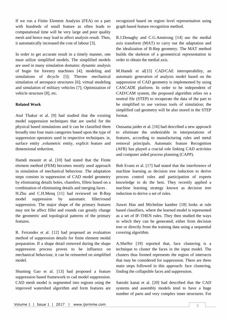
Related Work
Atul Thakur et al. [9] had studied that the existing
model suppression techniques that are useful for the
physical based simulations and it can be classified them
broadly into four main categories based upon the type of
suppression operators used in respective techniques. ie,
surface entity ,volumetric entity, explicit feature and
dimensional reduction.
Hamdi mounir et al. [10] had stated that the Finite
element method (FEM) becomes mostly used approach
in simulation of mechanical behaviour. The adaptation
steps consists in suppression of CAD model geometry
by eliminating details holes, chamfers, fillets based on a
combination of eliminating details and merging faces .
H.Zhu and C.H.Menq [11] had reviewed on B-Rep
model suppression by automatic fillet/round
suppression. The major shape of the primary features
may not be affect fillet and rounds can greatly change
the geometric and topological patterns of the primary
features.
R. Ferrandes et al. [12] had proposed an evaluation
method of suppression details for finite element modal
preparation. If a shape detail removed during the shape
suppression process proves to be influence on
mechanical behaviour, it can be reinserted on simplified
model.
Shuming Gao et al. [13] had proposed a feature
suppression based framework to cad model suppression.
CAD mesh model is segmented into regions using the
improved watershed algorithm and form features are
recognized based on region level representation using
graph based feature recognition method.
R.J.Donaghy and C.G.Amstrong [14] use the medial
axis transform (MAT) to carry out the adaptation and
the idealization of B-Rep geometry. The MAT method
builds the skeleton of a geometrical representation in
order to obtain the medial axis.
M.Hamdi et al[15] CAD/CAE interoperability, an
automatic generation of analysis model based on the
suppression of CAD geometry is implemented by using
CASCADE platform. In order to be independent of
CAD/CAM system, the proposed algorithm relies on a
neutral file (STEP) to recuperate the data of the part to
be simplified to use various tools of simulation; the
simplified cad geometry will be also stored in the STEP
format.
Oussama jaider et al. [16] had described a new approach
to eliminate the undesirable in interpretations of
features, according to manufacturing rules and metal
removal principals. Automatic feature Recognition
(AFR) has played a crucial role linking CAD activities
and computer aided process planning (CAPP).
Bob Evans et al. [17] had stated that the interference of
machine learning as decision tree induction to derive
process control rules and participation of experts
knowledge to do the best. They recently applied a
machine learning strategy known as decision tree
induction to derive a set of rules.
Jiawei Han and Micheline kamber [18] looks at rule
based classifiers, where the learned model is represented
as a set of IF-THEN rules. They then studied the ways
in which they can be generated; either from decision
tree or directly from the training data using a sequential
covering algorithm.
A.Sheffer [19] reported that, face clustering is a
technique to cluster the faces in the input model. The
clusters thus formed represents the region of intersects
that may be considered for suppression. There are three
main steps followed in this approach: face clustering,
finding the collapsible faces and suppression.
Satoshi kanai et al. [20] had described that the CAD
systems and assembly models tend to have a huge
number of parts and very complex inner structures. For
Volume 1 | Issue 1 | 2017 | www.ijsrmme.com
4
achieving the light weight and strengthened parts, the
inner structures of housing such as rib or bosses have
very complex geometries. In order to simplify this
complex geometry: Remove invisible technique is used.
In this paper utilizes two different approaches to
simplify the cad model. The first approach is knowledge
based. In this approach the knowledge is gain from
experts demo’s and encoded that data as suppression
rule. It is also called as a rule based approaches. The
rules shows that whether the feature /part that should be
considered for suppression or not.
The second approach is using hybrid method of
suppression. In this approach consists of following
phases. The phase A consists of step of pre-treatment of
CAD model. The phase B consists in identifying details
for details for suppression. The phase C consists of
allows suppression and reconstruction of simplified
model. For this approaches the open cascade platform is
utilized.
II. METHODS AND MATERIAL
In this session has been divided into two main phases.
First phase consists of knowledge based approach and
second phase leads to suppression by hybrid approach.
The overview of this approaches are discussed below.
1. Overview of Knowledge Based Approach
The proposed approach is to design an automated tool to
identifying the features capable for suppression. The
overall approach for generating a CAD suppression
using rule based approach as shown below.
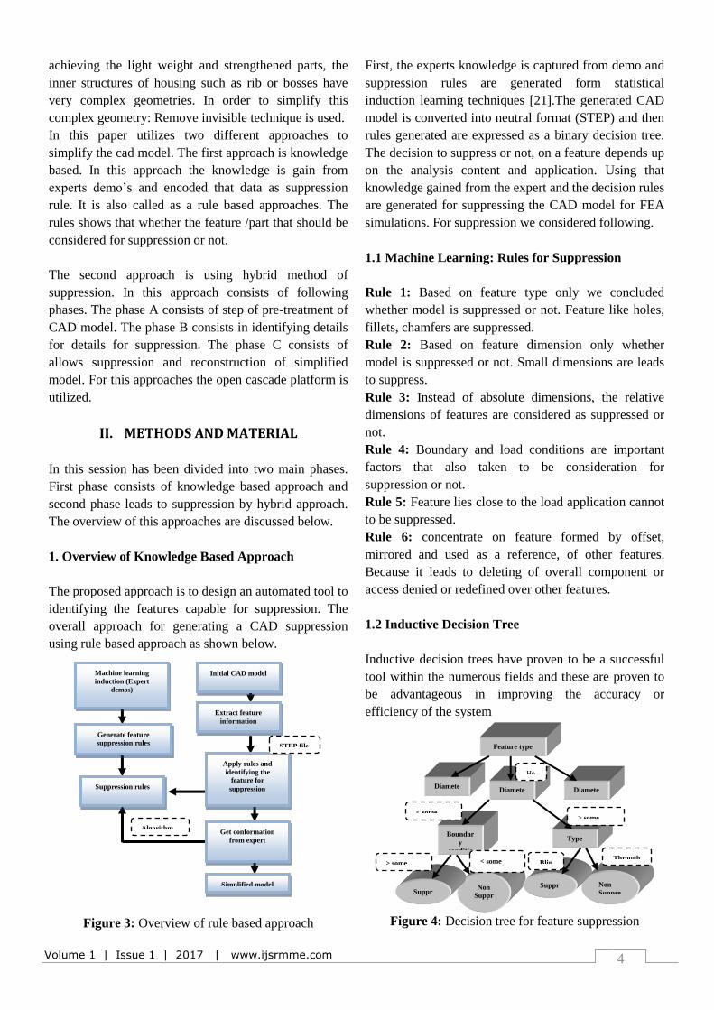
Figure 3: Overview of rule based approach
First, the experts knowledge is captured from demo and
suppression rules are generated form statistical
induction learning techniques [21].The generated CAD
model is converted into neutral format (STEP) and then
rules generated are expressed as a binary decision tree.
The decision to suppress or not, on a feature depends up
on the analysis content and application. Using that
knowledge gained from the expert and the decision rules
are generated for suppressing the CAD model for FEA
simulations. For suppression we considered following.
1.1 Machine Learning: Rules for Suppression
Rule 1: Based on feature type only we concluded
whether model is suppressed or not. Feature like holes,
fillets, chamfers are suppressed.
Rule 2: Based on feature dimension only whether
model is suppressed or not. Small dimensions are leads
to suppress.
Rule 3: Instead of absolute dimensions, the relative
dimensions of features are considered as suppressed or
not.
Rule 4: Boundary and load conditions are important
factors that also taken to be consideration for
suppression or not.
Rule 5: Feature lies close to the load application cannot
to be suppressed.
Rule 6: concentrate on feature formed by offset,
mirrored and used as a reference, of other features.
Because it leads to deleting of overall component or
access denied or redefined over other features.
1.2 Inductive Decision Tree
Inductive decision trees have proven to be a successful
tool within the numerous fields and these are proven to
be advantageous in improving the accuracy or
efficiency of the system
Figure 4: Decision tree for feature suppression
Initial CAD model
Extract feature
information
Apply rules and
identifying the
feature for
suppression
Get conformation
from expert
Simplified model
Machine learning
induction (Expert
demos)
Generate feature
suppression rules
Suppression rules
STEP file
Algorithm
Non
Suppr
ess
Suppr
ess
Non
Suppre
ss
Suppr
ess
Feature type
Diamete
r
Diamete
r
Diamete
r
Boundar
y
conditio
Type
Ho
> some < some
BlinThrough
> some < some
value
Volume 1 | Issue 1 | 2017 | www.ijsrmme.com
5
The above is an example of a representative decision
tree for suppressing a hole feature considering attributes
diameter, minimum distance to the boundary condition
feature, and the geometric type. The left node is the
node that should be executed if the condition is true.
The right node is the node that should be executed if the
condition is false.
Example algorithm for the above flow chart for
suppression of holes using decision tree induction as
shown below.
1.3 Algorithm for feature suppression
Algorithm: Rule 1
if feature type ==hole
get diameter value (min)
then (DIAMETER (D) <5)
if boundary condition. Distance (d) <5
then
The feature leads to be suppressed
Else The feature could not be suppressed
End if
End if
Algorithm: Rule 2
if feature type = = hole
get diameter value (min)
then (DIAMETER (D) <5)
if Hole type = = blind
then The feature is to be suppressed
else
if Hole type = =through
then The feature could not be suppressed.
End if
End if
End if
1.4 Implementation and validation on example
Implementation of Approach
The data processing implementation of suppression
approach was carried out on CATIA V5 software. In
that the API development’s platform:
“Knowledgeware”. Knowledgeware a special tool
developed for 3D applications of CAD-CAM
multiplatform. This platform is installed by using API
toolkit installer and it is based on visual basic language.
Example of Validation
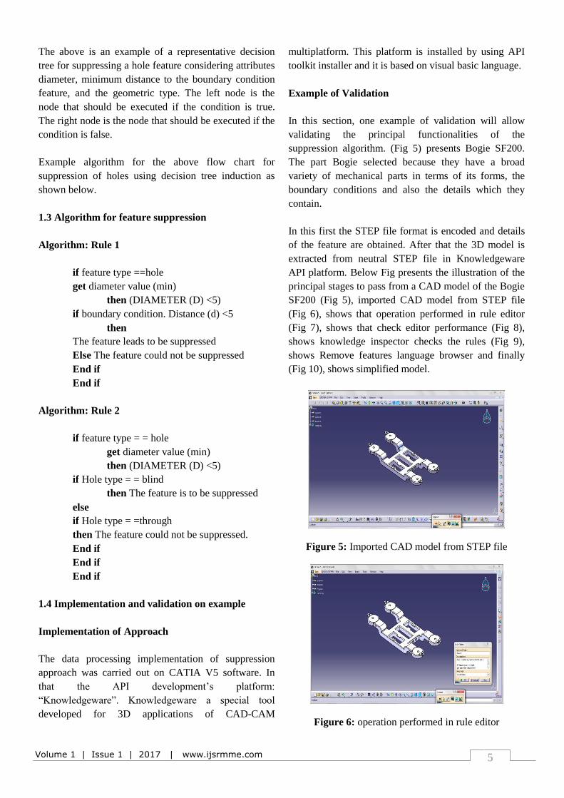
In this section, one example of validation will allow
validating the principal functionalities of the
suppression algorithm. (Fig 5) presents Bogie SF200.
The part Bogie selected because they have a broad
variety of mechanical parts in terms of its forms, the
boundary conditions and also the details which they
contain.
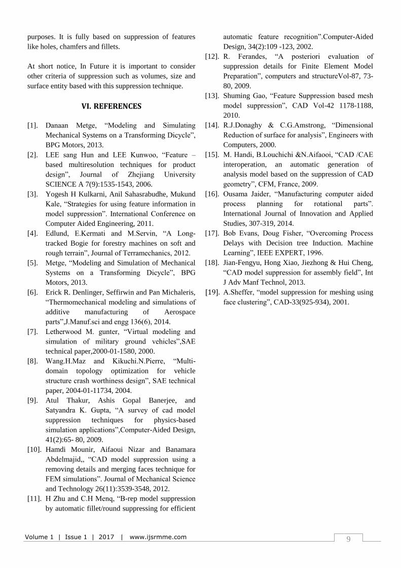
In this first the STEP file format is encoded and details
of the feature are obtained. After that the 3D model is
extracted from neutral STEP file in Knowledgeware
API platform. Below Fig presents the illustration of the
principal stages to pass from a CAD model of the Bogie
SF200 (Fig 5), imported CAD model from STEP file
(Fig 6), shows that operation performed in rule editor
(Fig 7), shows that check editor performance (Fig 8),
shows knowledge inspector checks the rules (Fig 9),
shows Remove features language browser and finally
(Fig 10), shows simplified model.
Figure 5: Imported CAD model from STEP file
Figure 6: operation performed in rule editor

Volume 1 | Issue 1 | 2017 | www.ijsrmme.com
6
Figure 7: Check Editor Performance
Figure 8: Knowledge Inspector Checks the Rules
Figure 9: Remove Features
Figure 10: Simplified Model
2 Overview of Hybrid Approach
In order to be independent of the CAD-CAM systems,
the proposed algorithm relies on a neutral file (STEP) to
recuperate the data of the part to be simplified. To use
various tools of simulation, the simplified CAD
geometry will be also stored under the same neutral
format (STEP). The overview diagram for hybrid
approach is shown below. It consists of three main
stages in simplifying of CAD model. This original
vision enables designer to visualize the least influential
zones (high order of criticality) on the computation
results, giving him the possibility either to inter-actively
eliminate the entities which have high order of
criticality, or to appeal to automatic algorithms of
elimination.
Figure 11: Overview of hybrid approach
2.1 Stage1: Initial CAD model
The stage (1) of the algorithm consists of a phase of
identification of details. The structured information
relates to the faces, wires, the edges and the vertex
which includes the geometry model of the part.
Figure 12:Initial CAD model
Stage 1
Stage 2
Stage 3
Initial Cad Model
Identification of
details
Identification of
Izo-zones
Remove and
Reconstruction of
model
Simplified CAD
Model
STEP file

Volume 1 | Issue 1 | 2017 | www.ijsrmme.com
7
2.2 Stage2: Identification of details
The stage (2) consists in identifying the Iso-zone for
elimination. That implies the implementation of
algorithms of identification based on feature
recognition. The result of this phase is a representation
of Iso-zones targets for elimination. These Iso-zones are
entities (edges, faces, chamfers, fillets, and rounds)
colored according to a gradient of criticality.
Figure 13: Identification of details(edges, faces,
Izo-zones)
2.3 Stage3: Remove and Reconstruction of model
The stage (3) consists in removing the identified details,
then in rebuilding the geometrical model after
suppression. The result of this phase is a simplified
CAD model whose elementary topology is valid. At the
exit of the algorithm, the designer has at his disposal a
simplified model recorded in format STEP for a
simulation by finite elements.
Figure 14 : Remove and Reconstruction of model
2.4 Implementation and validation on example
Implementation of approach
The data processing implementation of suppression
approach was carried out on open CASCADE platform.
Open CASCADE a special tool developed for 3D
applications of CAD-CAM multiplatform. This platform
available freely in open source on internet ant it is based
on C++ language encoding.
Example of Validation
In this section, one example of validation will allow
validating the principal functionalities of the
suppression algorithm. Fig presents Bogie SF200. The
part Bogie selected because they have a broad variety of
mechanical parts in terms of its forms, the boundary
conditions and also the details which they contain.
Figure 15 : Initial CAD model (STEP FORMAT)
Figure 16 : Identification of Izo-zones
Figure 17 : Simplified model

Volume 1 | Issue 1 | 2017 | www.ijsrmme.com
8
III. RESULTS AND DISCUSSION
The below figures shows that the analysed models using
ANSYS 14.0.Fig (18) shows analysis of original model
it has an equivalent Von-mises stress of 1.8745e5 Max
and analysis time taken as 38 s. Fig (19) shows analysis
of simplified model using knowledge based approach it
has an equivalent Von-mises stress of 1.4891e5 Max
and analysis time taken as 16 s. Fig (20) shows analysis
of simplified model using knowledge based approach it
has an equivalent Von-mises stress of 1.4236e5 Max
and analysis time taken as 12 s.
Figure 18 :Analysis of original model
Figure 19 :Analysis of simplified model (Knowledge
based approach)
Figure 20 :Analysis of simplified model (Hybrid
approach)
The below Chart 1 shows that the comparison of CAD
model suppression techniques based on Equivalent Von-
mises stress and chart 2 shows comparison of
computation time reduction.
0.00E+00
5.00E+04
1.00E+05
1.50E+05
2.00E+05
Max stress
original model
simplifiedknowledgebased
simplifiedHybridapproach
Chart 1: Equivalent Von-mises Stress comparison
Chart 2: Comparison of Computational Time
IV. CONCLUSION
This paper presents an estimating the effect of
suppression algorithm on CAD models for a simulation
by finite element method. The algorithm proposed
consists on reading the B- rep model of the CAD
geometry in order to identify, then to remove the details
considered superfluous for mechanical analysis.
The example of validation show that a suitable
elimination of the details in a CAD model allows saving
a very important time (up to 69%) in the procedure of
simulation while keeping a high quality of the
computation results. These observations were found by
doing simulations by finite elements before and after
suppression. This work helps to the industrialists who
are interested more and more in preparing CAD models
for simulation purposes. Thus, the comparison shows
hybrid approach gives acceptable results with minimum
error.
V. SCOPE AND FUTURE WORK
This work helps to the industrialists who are interested
more and more in preparing CAD models for simulation
0 20 40co
mp
uta
tio
n T
ime
Hybrid Approach
Knowledge basedApproach
Original model
Volume 1 | Issue 1 | 2017 | www.ijsrmme.com
9
purposes. It is fully based on suppression of features
like holes, chamfers and fillets.
At short notice, In Future it is important to consider
other criteria of suppression such as volumes, size and
surface entity based with this suppression technique.
VI. REFERENCES
[1]. Danaan Metge, “Modeling and Simulating
Mechanical Systems on a Transforming Dicycle”,
BPG Motors, 2013.
[2]. LEE sang Hun and LEE Kunwoo, “Feature –
based multiresolution techniques for product
design”, Journal of Zhejiang University
SCIENCE A 7(9):1535-1543, 2006.
[3]. Yogesh H Kulkarni, Anil Sahasrabudhe, Mukund
Kale, “Strategies for using feature information in
model suppression”. International Conference on
Computer Aided Engineering, 2011.
[4]. Edlund, E.Kermati and M.Servin, “A Long-
tracked Bogie for forestry machines on soft and
rough terrain”, Journal of Terramechanics, 2012.
[5]. Metge, “Modeling and Simulation of Mechanical
Systems on a Transforming Dicycle”, BPG
Motors, 2013.
[6]. Erick R. Denlinger, Seffirwin and Pan Michaleris,
“Thermomechanical modeling and simulations of
additive manufacturing of Aerospace
parts”,J.Manuf.sci and engg 136(6), 2014.
[7]. Letherwood M. gunter, “Virtual modeling and
simulation of military ground vehicles”,SAE
technical paper,2000-01-1580, 2000.
[8]. Wang.H.Maz and Kikuchi.N.Pierre, “Multi-
domain topology optimization for vehicle
structure crash worthiness design”, SAE technical
paper, 2004-01-11734, 2004.
[9]. Atul Thakur, Ashis Gopal Banerjee, and
Satyandra K. Gupta, “A survey of cad model
suppression techniques for physics-based
simulation applications”,Computer-Aided Design,
41(2):65- 80, 2009.
[10]. Hamdi Mounir, Aifaoui Nizar and Banamara
Abdelmajid,, “CAD model suppression using a
removing details and merging faces technique for
FEM simulations”. Journal of Mechanical Science
and Technology 26(11):3539-3548, 2012.
[11]. H Zhu and C.H Menq, “B-rep model suppression
by automatic fillet/round suppressing for efficient
automatic feature recognition”.Computer-Aided
Design, 34(2):109 -123, 2002.
[12]. R. Ferandes, “A posteriori evaluation of
suppression details for Finite Element Model
Preparation”, computers and structureVol-87, 73-
80, 2009.
[13]. Shuming Gao, “Feature Suppression based mesh
model suppression”, CAD Vol-42 1178-1188,
2010.
[14]. R.J.Donaghy & C.G.Amstrong, “Dimensional
Reduction of surface for analysis”, Engineers with
Computers, 2000.
[15]. M. Handi, B.Louchichi &N.Aifaooi, “CAD /CAE
interoperation, an automatic generation of
analysis model based on the suppression of CAD
geometry”, CFM, France, 2009.
[16]. Ousama Jaider, “Manufacturing computer aided
process planning for rotational parts”.
International Journal of Innovation and Applied
Studies, 307-319, 2014.
[17]. Bob Evans, Doug Fisher, “Overcoming Process
Delays with Decision tree Induction. Machine
Learning”, IEEE EXPERT, 1996.
[18]. Jian-Fengyu, Hong Xiao, Jiezhong & Hui Cheng,
“CAD model suppression for assembly field”, Int
J Adv Manf Technol, 2013.
[19]. A.Sheffer, “model suppression for meshing using
face clustering”, CAD-33(925-934), 2001.