Failure Mode and Effects Analysis System FMEA Design FMEA Process FMEA.
Cabin Ace-2™ User’s Manual Version 1.0.3
Telefonix Inflight Entertainment and Connectivity Systems
THIS DOCUMENT IS THE SOLE PROPERTY OF TELEFONIX, INCORPORATED AND SHALL NOT BE REPRODUCED, COPIED OR ISSUED AS THE BASIS OF MAINTENANCE OR SALE OF APPARATUS W IHTOUT PERMISSION OF TELEFONIX, INCORPORATED.
Copyright © Copyright 2017 Telefonix, Inc. Telefonix PDT trademarks include , Cabin Ace-2™, Cabin Ace™, Cabin Pinnacle™, Cabin Vista™, Edge ™, All rights reserved. All other trademarks are the property of their respective owners.
Open Source Code This product includes code licensed under GNU General Public License, and/or certain other open source licenses.
FCC COMPLIANCE STATEMENT CAUTION: Changes or modifications not expressly approved could void your authority to use this equipment This device complies with Part 15 of the FCC Rules. Operation to the following two conditions: (1) This device may not cause harmful interference, and (2) this device must accept any interference received, including interference that may cause undesired operation
INDUSTRY CANADA STATEMENT This device complies with Industry Canada licence-exempt RSS standard(s). Operation is subject to the following two conditions: (1) this device may not cause interference, and (2) this device must accept any interference, including interference that may cause undesired operation of the device.
Le présent appareil est conforme aux CNR d'Industrie Canada applicables aux appareils radio exempts de licence. L'exploitation est autorisée aux deux conditions suivantes : (1) l'appareil ne doit pas produire de brouillage, et (2) l'utilisateur de l'appareil doit accepter tout brouillage radioélectrique subi, même si le brouillage est susceptible d'en compromettre le fonctionnement.
2 of 48 Revision Date | July 10, 2017 || Document Number | UM-E71-308-01 || Rev C
Revision Date | July 10, 2017 || Document Number | UM-E71-308-01 || Rev C 3 of 48
TABLE OF CONTENTS
1 User Information.................................................................................................................................... 5
1.1 Support Documentation ................................................................................................................ 5 1.2 Industry Standards ........................................................................................................................ 6 1.3 Warranty........................................................................................................................................ 6 1.4 Exclusion of Liability Notice........................................................................................................... 6
2 Important Safety Instructions ................................................................................................................ 7 3 Introduction............................................................................................................................................ 8
3.1 Product Description ....................................................................................................................... 8 3.2 Hardware Architecture .................................................................................................................. 8 3.3 Key Hardware Components .......................................................................................................... 9 3.4 Orderable Part Numbers ............................................................................................................. 10
4 Starting Up .......................................................................................................................................... 12
4.1 Power Up..................................................................................................................................... 12 4.2 Startup process ........................................................................................................................... 12 4.3 IP Strapping Table ...................................................................................................................... 16 4.4 Connecting using the Console Port ............................................................................................ 16 4.5 Connecting using Web-based GUI ............................................................................................. 18 4.6 Virtual Controller Architecture ..................................................................................................... 20 4.7 WLAN Setup................................................................................................................................ 23
5 Physical I/O ......................................................................................................................................... 28
5.1 Connections and Cabling ............................................................................................................ 28 5.2 Maintenance Connectors ............................................................................................................ 30 5.3 Status Indicators ......................................................................................................................... 30
6 Performance Data ............................................................................................................................... 32
6.1 Radio Characteristics .................................................................................................................. 32 6.2 RF Performance Table ................................................................................................................ 33 6.3 Country Codes ............................................................................................................................ 34 6.4 RF testing .................................................................................................................................... 36
7 Technical Data .................................................................................................................................... 39
7.1 Electrical and Environmental Specifications ............................................................................... 39 7.2 Mechanical Design and Dimensions ........................................................................................... 42 7.3 Grounding and Bonding .............................................................................................................. 46 7.4 Workmanship .............................................................................................................................. 46 7.5 Safety .......................................................................................................................................... 46 7.6 Protective Devices ...................................................................................................................... 46
8 Reliability and Maintainability .............................................................................................................. 47
8.1 Reliability ..................................................................................................................................... 47 8.2 Maintainability.............................................................................................................................. 47 8.3 Mean Time to Repair (MTTR) ..................................................................................................... 47 8.4 Failure Detection and Fault Isolation .......................................................................................... 47 8.5 Production Testing ...................................................................................................................... 47
9 Support and Service............................................................................................................................ 48
9.1 Technical Support ....................................................................................................................... 48 9.2 Returning Defective Equipment .................................................................................................. 48
Revision Date | July 10, 2017 || Document Number | UM-E71-308-01 || Rev C 4 of 48
Table of Tables
Table 1: Telefonix PDT Support Documentation .......................................................................................... 5 Table 2: Aruba Support Documentation........................................................................................................ 5 Table 3: Industry Standards .......................................................................................................................... 6 Table 4: Cabin ACe-2 Orderable Part Numbers ......................................................................................... 10 Table 5: IP Strapping Table ........................................................................................................................ 16 Table 6: CWAP External Connector Interfaces........................................................................................... 28 Table 7: AP LED Operation......................................................................................................................... 30 Table 8: Radio Characteristics .................................................................................................................... 32 Table 9: 2.4GHz Maximum Conducted Output Power................................................................................ 33 Table 10: 5GHz Maximum Conducted Output Power................................................................................. 33 Table 11: Country Codes ............................................................................................................................ 34 Table 12: Qualification Test Matrix - Environment ...................................................................................... 39 Table 13: Qualification Test Matrix - EMI .................................................................................................... 40
Table of Figures
Figure 1: CWAP Wave 2 System Block Diagram ....................................................................................... 10 Figure 2: Cabin ACe-2 Equipment .............................................................................................................. 11 Figure 3: Example Console Output of the SIB Boot Process ..................................................................... 13 Figure 4: Example Console Output of the AP Boot Process ...................................................................... 14 Figure 5: Aruba Instant GUI Login Prompt.................................................................................................. 18 Figure 6: The Six Sections of the Aruba Instant Main GUI Page................................................................ 19 Figure 7: The System Username and Password can be changed on the Admin tab of the System Dialog Box. ............................................................................................................................................................. 20 Figure 8: The Virtual Controller Name and Static IP Address can be set in the System Dialog Box. ........ 21 Figure 9: The Edit Access Point Dialog Box. .............................................................................................. 22 Figure 10: The Four Stages to Creating an SSID ....................................................................................... 23 Figure 11: The WLAN Settings Tab of the New WLAN Dialog Box ............................................................ 24 Figure 12: The VLAN Tab of the New WLAN Dialog Box ........................................................................... 25 Figure 13: Configuring an External RADIUS Server from the Security Tab of the New WLAN Dialog Box26 Figure 14: Configuring Firewall Rules from the Access Tab of the New WLAN Dialog Box ...................... 27 Figure 15: J1 (Pins) Connector Layout and Pin Definitions ........................................................................ 28 Figure 16: J2 (Socket) Connector Layout and Pin Definitions .................................................................... 29 Figure 17: J3 (Socket) Connector Layout and Pin Definitions .................................................................... 29 Figure 18: Azimuth test setup (top view)..................................................................................................... 36 Figure 19: 2.45GHz Wi-Fi Average Azimuth (antennas 1, 2, 3, 4) ............................................................ 37 Figure 20: 5GHz WiFi Average Azimuth (antennas A, B, C, D)................................................................. 38 Figure 21: CWAP Top View ........................................................................................................................ 42 Figure 22:CWAP I/O Front View ................................................................................................................. 43 Figure 23: CWAP Side View - Right ........................................................................................................... 43 Figure 24: CWAP Side View - Left .............................................................................................................. 43 Figure 25: CWAP Rear View....................................................................................................................... 44 Figure 26: CWAP Bottom View ................................................................................................................... 44
Revision Date | July 10, 2017 || Document Number | UM-E71-308-01 || Rev C 5 of 48
1 User Information
This User’s Manual describes the features supported by Telefonix PDT Cabin Wireless Access Point (CWAP), Wave 2, branded as Cabin Ace-2TM and provides detailed instructions for setting up and configuring the Cabin ACe-2 wireless access point.
This guide is intended for administrators who configure and use Cabin ACe-2.
1.1 Support Documentation
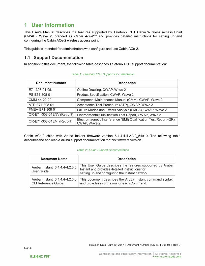
In addition to this document, the following table describes Telefonix PDT support documentation:
Table 1: Telefonix PDT Support Documentation
Document Number Description
E71-308-01-OL Outline Drawing, CWAP, Wave 2 PS-E71-308-01 Product Specification, CWAP, Wave 2 CMM-44-20-29 Component Maintenance Manual (CMM), CWAP, Wave 2 ATP-E71-308-01 Acceptance Test Procedure (ATP), CWAP, Wave 2 FMEA-E71-308-01 Failure Modes and Effects Analysis (FMEA), CWAP, Wave 2 QR-E71-308-01ENV (Retrofit) Environmental Qualification Test Report, CWAP, Wave 2
QR-E71-308-01EMI (Retrofit) Electromagnetic Interference (EMI) Qualification Test Report (QR), CWAP, Wave 2
Cabin ACe-2 ships with Aruba Instant firmware version 6.4.4.4-4.2.3.2_54910. The following table describes the applicable Aruba support documentation for this firmware version.
Table 2: Aruba Support Documentation
Document Name Description
Aruba Instant 6.4.4.4-4.2.3.0 User Guide
This User Guide describes the features supported by Aruba Instant and provides detailed instructions for setting up and configuring the Instant network.
Aruba Instant 6.4.4.4-4.2.3.0 CLI Reference Guide
This document describes the Aruba Instant command syntax and provides information for each Command.
Revision Date | July 10, 2017 || Document Number | UM-E71-308-01 || Rev C 6 of 48
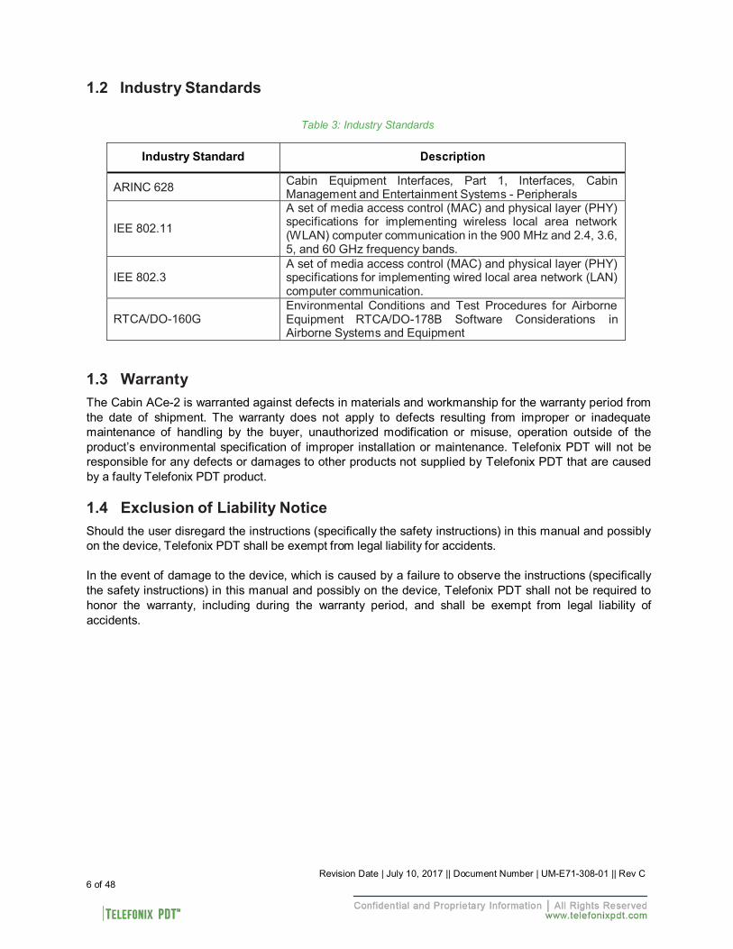
1.2 Industry Standards
Table 3: Industry Standards
Industry Standard
Description
ARINC 628 Cabin Equipment Interfaces, Part 1, Interfaces, Cabin Management and Entertainment Systems - Peripherals
IEE 802.11
A set of media access control (MAC) and physical layer (PHY) specifications for implementing wireless local area network (WLAN) computer communication in the 900 MHz and 2.4, 3.6, 5, and 60 GHz frequency bands.
IEE 802.3
A set of media access control (MAC) and physical layer (PHY) specifications for implementing wired local area network (LAN) computer communication.
RTCA/DO-160G
Environmental Conditions and Test Procedures for Airborne Equipment RTCA/DO-178B Software Considerations in Airborne Systems and Equipment
1.3 Warranty
The Cabin ACe-2 is warranted against defects in materials and workmanship for the warranty period from the date of shipment. The warranty does not apply to defects resulting from improper or inadequate maintenance of handling by the buyer, unauthorized modification or misuse, operation outside of the product’s environmental specification of improper installation or maintenance. Telefonix PDT will not be responsible for any defects or damages to other products not supplied by Telefonix PDT that are caused by a faulty Telefonix PDT product.
1.4 Exclusion of Liability Notice
Should the user disregard the instructions (specifically the safety instructions) in this manual and possibly on the device, Telefonix PDT shall be exempt from legal liability for accidents.
In the event of damage to the device, which is caused by a failure to observe the instructions (specifically the safety instructions) in this manual and possibly on the device, Telefonix PDT shall not be required to honor the warranty, including during the warranty period, and shall be exempt from legal liability of accidents.
Revision Date | July 10, 2017 || Document Number | UM-E71-308-01 || Rev C 7 of 48
2 Important Safety Instructions
The following general instructions should always be followed in order to assure the proper operation of Cabin ACe-2, the safety of operators and the preservation of warranty coverage.
1. Avoid removing any identification plates, serial numbers or warning labels unless specifically authorized by the manufacturer.
2. Please observe all specified dimensions required for mounting included in the Outline Drawing,
Telefonix PDT Document E71-308-01-OL.
3. When installing the Cabin ACe-2, there must be at least 1.00” free space to the left, right, top and rear of the unit to prevent the system overheating.
4. Leave at least 3.00” of free space to the front of the unit in order to have access to the connector
interfaces to properly connect the peripherals.
5. Attach the Cabin ACe-2 firmly to a clean flat and solid mounting surface. Use proper fastening materials suitable for the mounting surface. Ensure that the mounting surface type and the mounting solution safely support the load of the Cabin ACe-2 and the attached components.
6. Follow the local/national regulations for grounding. A ground bonding measurement between the
Cabin ACe-2 and the mounting surface should be conducted to ensure proper safety and EMI characteristics are maintained.
7. The voltage feeds must not be overloaded. Adjust the cabling and external overcharge protection
to correspond with the electrical data indicated on the type label. For detailed interconnection of power and signal wiring, refer to the Section 4 (Starting Up) and Section 5 (Physical I/O).
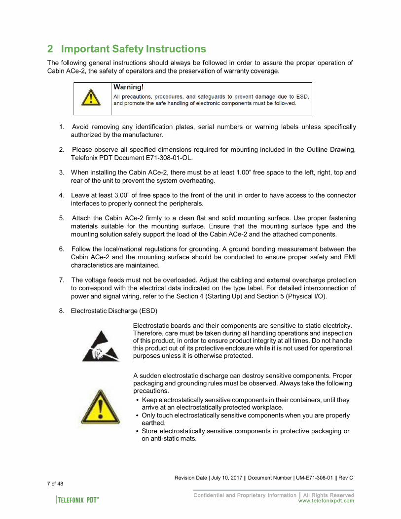
8. Electrostatic Discharge (ESD)
Electrostatic boards and their components are sensitive to static electricity. Therefore, care must be taken during all handling operations and inspection of this product, in order to ensure product integrity at all times. Do not handle this product out of its protective enclosure while it is not used for operational purposes unless it is otherwise protected.
A sudden electrostatic discharge can destroy sensitive components. Proper packaging and grounding rules must be observed. Always take the following precautions. • Keep electrostatically sensitive components in their containers, until they
arrive at an electrostatically protected workplace. • Only touch electrostatically sensitive components when you are properly
earthed. • Store electrostatically sensitive components in protective packaging or
on anti-static mats.
3 Introduction 3.1 Product Description
The Telefonix, Inc. Cabin Wireless Access Point (CWAP) is a network distribution system designed specifically for commercial aircraft applications. The CWAP supports IEEE 802.11ac, Wave 2 functionality, and is backwards compatible with 802.11a/b/g/n. The CWAP leverages the use of a COTS wireless access point to facilitate wireless communications to wireless client radios in the aircraft cabin, as well as other devices on the network. The CWAP provides a bridge between IEEE 802.3 wired Ethernet LANs and IEEE 802.11a/b/g/n/ac compliant wireless networks.
The unit is provided with aircraft level discrete inputs and outputs to facilitate event notification to and from other aircraft systems, including remote management of the ON/OFF function. The unit is equipped with an aircraft grade AC power supply capable of operating from 115VAC, 360 Hz – 800 Hz power with a 200 millisecond hold-up capability for power interruptions. The CWAP does not require active cooling system. The unit communicates to a host server by physical connection over a Gigabit Ethernet wired interface either in a “Daisy chain” or “Star” network topology environment.
This Product Specification pertains to a CWAP with integrated antennas supporting both 2.4GHz and 5GHz bands.
This unit is identified as Telefonix PDTP/N: E71-308-01 and is branded as Cabin Ace-2TM. 3.2 Hardware Architecture
The CWAP leverages a state-of-the-art, commercial enterprise-class Wireless Access Point (AP). The AP selected for this application is manufactured by Aruba Networks, a Hewlett Packard Enterprise company, The Aruba model IAP-325 has been ruggedized and repackaged to meet the operational requirements of commercial aircraft environment. The CWAP meets the electrical and mechanical requirements of ARINC 628.
The Cabin ACe-2 feature set includes:
• IEEE 802.11ac, Wave 2 based architecture.
• Dual radios for 2.4GHz and 5.8GHz (all U-NII channelization) simultaneous operation.
• 4x4 SU-MIMO, 4 spatial stream operation.
• 3x3 MU-MIMO, 3 spatial stream operation.
• Integrated antennas with adaptive beam forming for enhanced throughput capabilities
• Support for up to 255x associated clients devices per radio and 16x BSSID per radio
• Fully autonomous without requiring a separate wireless controller
• Support for World Wide (-WW) operation via the CLI which can automatically configure the CWAP in accordance with location information (provided by the aircraft) to pre-set regulatory domains (country codes) stored within the CWAP
• Discrete Inputs to control remote ON/OFF and RF Enable
• Discrete output for PSU and AP status
• IP Address strapping bits
• Support for input power pass thru to downstream CWAPs
• Aircraft grade AC power supply unit with 200 milliseconds of hold-up capacity
8 of 48 Revision Date | July 10, 2017 || Document Number | UM-E71-308-01 || Rev C
Revision Date | July 10, 2017 || Document Number | UM-E71-308-01 || Rev C 9 of 48
• Support for pass thru Ethernet to downstream CWAPs
• Redundant power supply (on SIB) to support Ethernet by-pass in the event of a CWAP power supply failure
• Lightweight and compact electro-mechanical packaging
• Connectors:
o EN4165 style connectors for all I/O (per ARINC 628) o Micro USB for serial console connection
3.3 Key Hardware Components
The CWAP key hardware components include:
• Commercial Aruba AP “engine” with integrated antennas
• Signal Interface Board (SIB)
• Main AC/DC Power Supply Unit (PSU 1)
• SIB AC/DC Power Supply Unit (PSU 2)
• External connectors Interface for Power, Ethernet, Discrete I/O (per ARINC 628)
• Mechanical Housing per ARINC 628
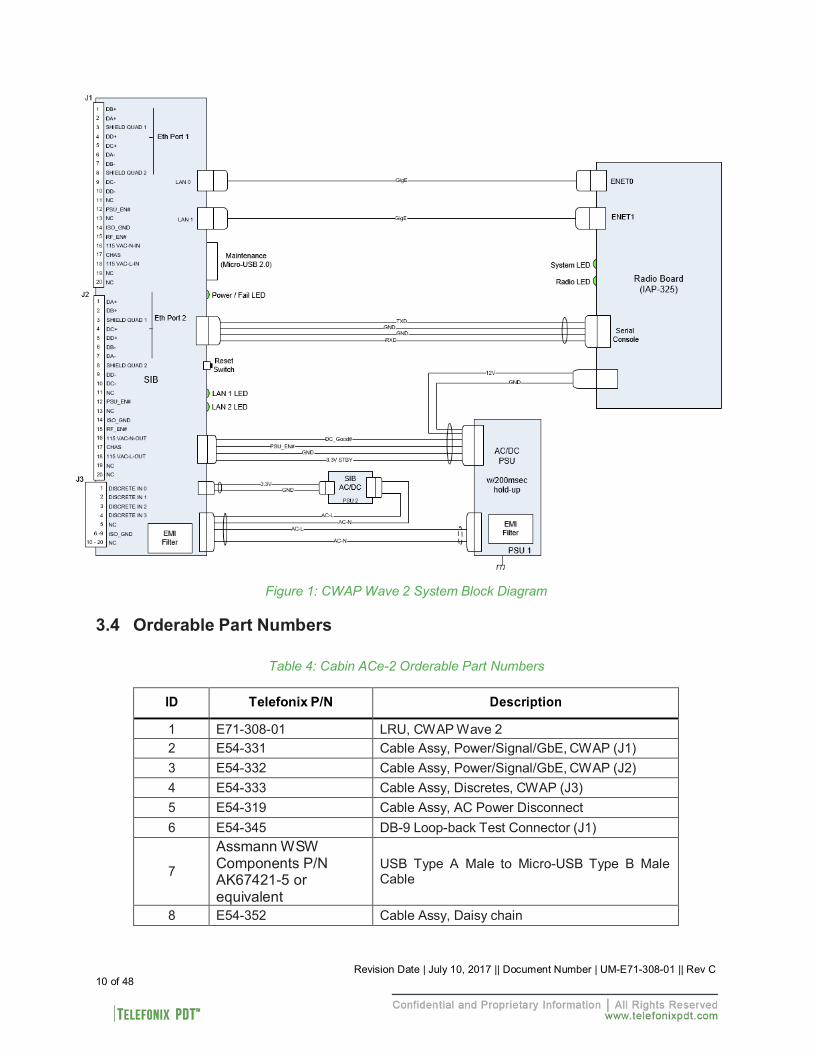
Figure 1 shows the CWAP System Block Diagram.
(Intentionally Left Blank)
Revision Date | July 10, 2017 || Document Number | UM-E71-308-01 || Rev C 10 of 48
Figure 1: CWAP Wave 2 System Block Diagram 3.4 Orderable Part Numbers
Table 4: Cabin ACe-2 Orderable Part Numbers
ID Telefonix P/N Description
1 E71-308-01 LRU, CWAP Wave 2 2 E54-331 Cable Assy, Power/Signal/GbE, CWAP (J1) 3 E54-332 Cable Assy, Power/Signal/GbE, CWAP (J2) 4 E54-333 Cable Assy, Discretes, CWAP (J3) 5 E54-319 Cable Assy, AC Power Disconnect 6 E54-345 DB-9 Loop-back Test Connector (J1)
7
Assmann WSW Components P/N AK67421-5 or equivalent
USB Type A Male to Micro-USB Type B Male Cable
8 E54-352 Cable Assy, Daisy chain
Revision Date | July 10, 2017 || Document Number | UM-E71-308-01 || Rev C 11 of 48
2 3
1
4 5
6 7 8
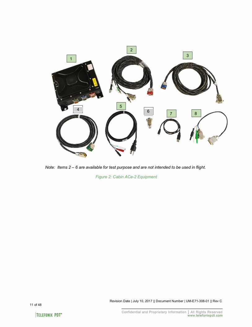
Note: Items 2 – 6 are available for test purpose and are not intended to be used in flight.
Figure 2: Cabin ACe-2 Equipment
4 Starting Up 4.1 Power Up
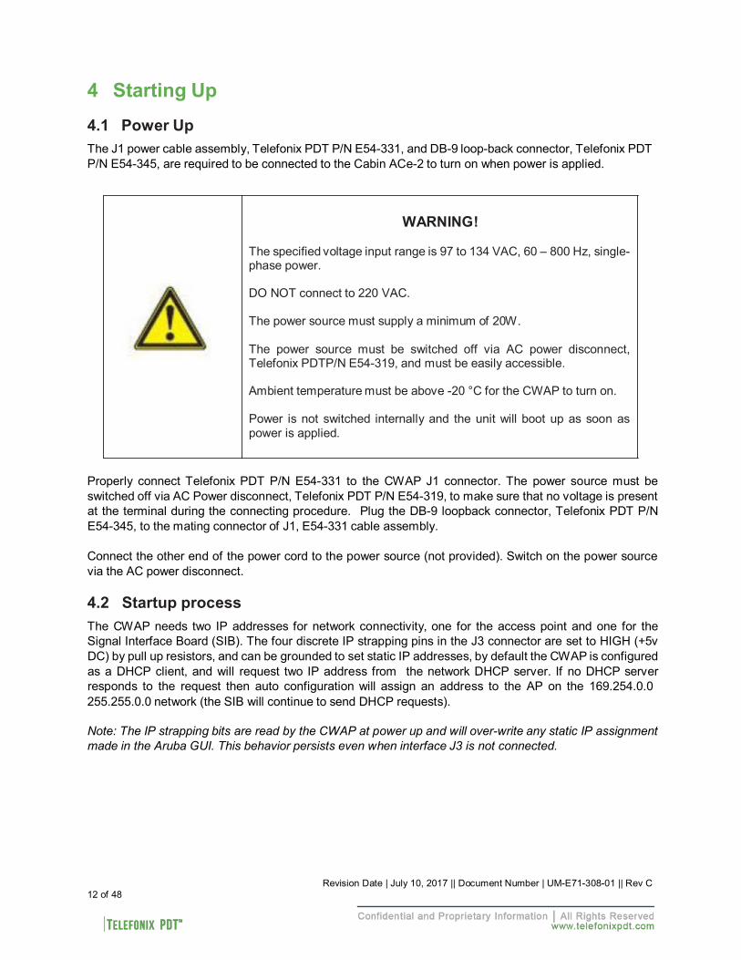
The J1 power cable assembly, Telefonix PDT P/N E54-331, and DB-9 loop-back connector, Telefonix PDT P/N E54-345, are required to be connected to the Cabin ACe-2 to turn on when power is applied.
WARNING!
The specified voltage input range is 97 to 134 VAC, 60 – 800 Hz, single- phase power.
DO NOT connect to 220 VAC.
The power source must supply a minimum of 20W.
The power source must be switched off via AC power disconnect, Telefonix PDTP/N E54-319, and must be easily accessible.
Ambient temperature must be above -20 °C for the CWAP to turn on.
Power is not switched internally and the unit will boot up as soon as power is applied.
Properly connect Telefonix PDT P/N E54-331 to the CWAP J1 connector. The power source must be switched off via AC Power disconnect, Telefonix PDT P/N E54-319, to make sure that no voltage is present at the terminal during the connecting procedure. Plug the DB-9 loopback connector, Telefonix PDT P/N E54-345, to the mating connector of J1, E54-331 cable assembly.
Connect the other end of the power cord to the power source (not provided). Switch on the power source via the AC power disconnect.
4.2 Startup process
The CWAP needs two IP addresses for network connectivity, one for the access point and one for the Signal Interface Board (SIB). The four discrete IP strapping pins in the J3 connector are set to HIGH (+5v DC) by pull up resistors, and can be grounded to set static IP addresses, by default the CWAP is configured as a DHCP client, and will request two IP address from the network DHCP server. If no DHCP server responds to the request then auto configuration will assign an address to the AP on the 169.254.0.0 255.255.0.0 network (the SIB will continue to send DHCP requests).
Note: The IP strapping bits are read by the CWAP at power up and will over-write any static IP assignment made in the Aruba GUI. This behavior persists even when interface J3 is not connected.
12 of 48 Revision Date | July 10, 2017 || Document Number | UM-E71-308-01 || Rev C
4.2.1 Boot Up
4.2.1.1 SIB Boot Up
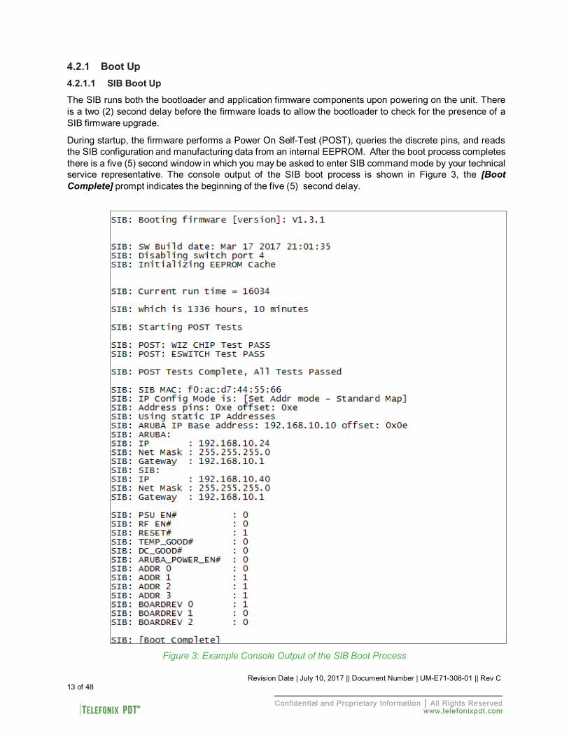
The SIB runs both the bootloader and application firmware components upon powering on the unit. There is a two (2) second delay before the firmware loads to allow the bootloader to check for the presence of a SIB firmware upgrade.
During startup, the firmware performs a Power On Self-Test (POST), queries the discrete pins, and reads the SIB configuration and manufacturing data from an internal EEPROM. After the boot process completes there is a five (5) second window in which you may be asked to enter SIB command mode by your technical service representative. The console output of the SIB boot process is shown in Figure 3, the [Boot Complete] prompt indicates the beginning of the five (5) second delay.
Figure 3: Example Console Output of the SIB Boot Process
13 of 48 Revision Date | July 10, 2017 || Document Number | UM-E71-308-01 || Rev C
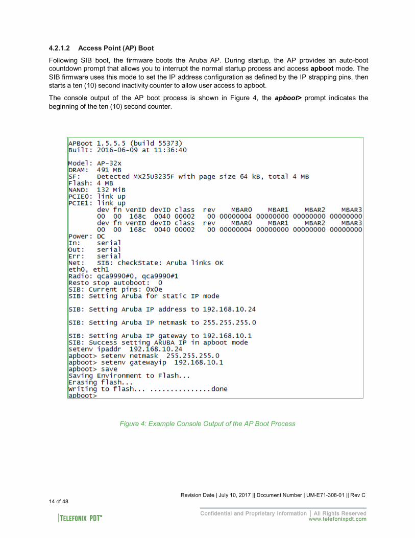
4.2.1.2 Access Point (AP) Boot
Following SIB boot, the firmware boots the Aruba AP. During startup, the AP provides an auto-boot countdown prompt that allows you to interrupt the normal startup process and access apboot mode. The SIB firmware uses this mode to set the IP address configuration as defined by the IP strapping pins, then starts a ten (10) second inactivity counter to allow user access to apboot.
The console output of the AP boot process is shown in Figure 4, the apboot> prompt indicates the beginning of the ten (10) second counter.
Figure 4: Example Console Output of the AP Boot Process
14 of 48 Revision Date | July 10, 2017 || Document Number | UM-E71-308-01 || Rev C
Revision Date | July 10, 2017 || Document Number | UM-E71-308-01 || Rev C 15 of 48
While in apboot mode you have access to the following commands:
? - alias for 'help' boot - boot the OS image clear - clear the OS image or other information date - get/set/reset date & time dhcp - invoke DHCP client to obtain IP/boot params factory_reset - reset to factory defaults help - print online help mfginfo - show manufacturing info ping - send ICMP ECHO_REQUEST to network host printenv - print environment variables purgeenv - restore default environment variables reset - Perform RESET of the CPU saveenv - save environment variables to persistent storage setenv - set environment variables tftpboot - boot image via network using TFTP protocol upgrade - upgrade the APBoot or OS image version - display version
The setenv command can be used to set the environment variables listed below. Enter commands one per line, replacing the equal sign with a space. To clear an environment variable, enter the variable name followed by <CR>.
bootdelay=2 baudrate=9600 autoload=n boardname=Talisker servername=aruba-master bootcmd=boot ap autostart=yes bootfile=mips32.ari ethaddr=d8:c7:c8:XX:XX:XX os_partition=0 ethact=eth0 gatewayip=192.168.1.1 netmask=255.255.255.0 dnsip=8.8.8.8 name=IAP105 domainname=arubanetworks.com ipaddr=192.168.1.101 stdin=serial stdout=serial stderr=serial
Revision Date | July 10, 2017 || Document Number | UM-E71-308-01 || Rev C 16 of 48
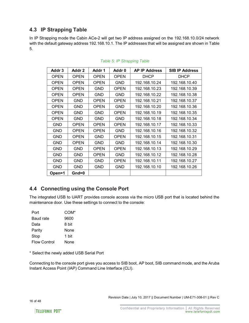
4.3 IP Strapping Table
In IP Strapping mode the Cabin ACe-2 will get two IP address assigned on the 192.168.10.0/24 network with the default gateway address 192.168.10.1. The IP addresses that will be assigned are shown in Table 5.
Table 5: IP Strapping Table
Addr 3 Addr 2 Addr 1 Addr 0 AP IP Address SIB IP Address OPEN OPEN OPEN OPEN DHCP DHCP OPEN OPEN OPEN GND 192.168.10.24 192.168.10.40 OPEN OPEN GND OPEN 192.168.10.23 192.168.10.39 OPEN OPEN GND GND 192.168.10.22 192.168.10.38 OPEN GND OPEN OPEN 192.168.10.21 192.168.10.37 OPEN GND OPEN GND 192.168.10.20 192.168.10.36 OPEN GND GND OPEN 192.168.10.19 192.168.10.35 OPEN GND GND GND 192.168.10.18 192.168.10.34 GND OPEN OPEN OPEN 192.168.10.17 192.168.10.33 GND OPEN OPEN GND 192.168.10.16 192.168.10.32 GND OPEN GND OPEN 192.168.10.15 192.168.10.31 GND OPEN GND GND 192.168.10.14 192.168.10.30 GND GND OPEN OPEN 192.168.10.13 192.168.10.29 GND GND OPEN GND 192.168.10.12 192.168.10.28 GND GND GND OPEN 192.168.10.11 192.168.10.27 GND GND GND GND 192.168.10.10 192.168.10.26
Open=1 Gnd=0
4.4 Connecting using the Console Port
The integrated USB to UART provides console access via the micro USB port that is located behind the maintenance door. Use these settings to connect to the console:
Port COM* Baud rate 9600 Data 8 bit Parity None Stop 1 bit Flow Control None
* Select the newly added USB Serial Port
Connecting to the console port gives you access to SIB boot, AP boot, SIB command mode, and the Aruba Instant Access Point (IAP) Command Line Interface (CLI).
Revision Date | July 10, 2017 || Document Number | UM-E71-308-01 || Rev C 17 of 48
The IAP CLI becomes available after completion of the startup process, and requires administrator credentials to start a session. The default credentials are:
User: admin Password: admin
After login, the privileged command mode is enabled which provides access to show, clear, ping, traceroute, and commit commands. The configuration commands are available in the configuration (config) mode. To move from privileged mode to the configuration mode, enter the following command at the command prompt:
(Cabin Ace) # configure terminal
The configure terminal command allows you to enter the basic configuration mode and the command prompt is displayed as follows:
(Cabin Ace) (config) #
Some commands in configuration mode allow you to enter into a sub-mode to configure the commands specific to that mode. When you are in a configuration sub-mode, the command prompt changes to indicate the current sub-mode.
You can exit a sub-command mode and return to the basic configuration mode or the privileged Exec (enable) mode at any time by executing the exit or end command.
You can use the question mark (?) to view the commands available for your current mode.
Refer to the Aruba Instant 6.4.4.4-4.2.3.0 CLI Reference Guide, for additional information on the IAP CLI.
4.5 Connecting using Web-based GUI
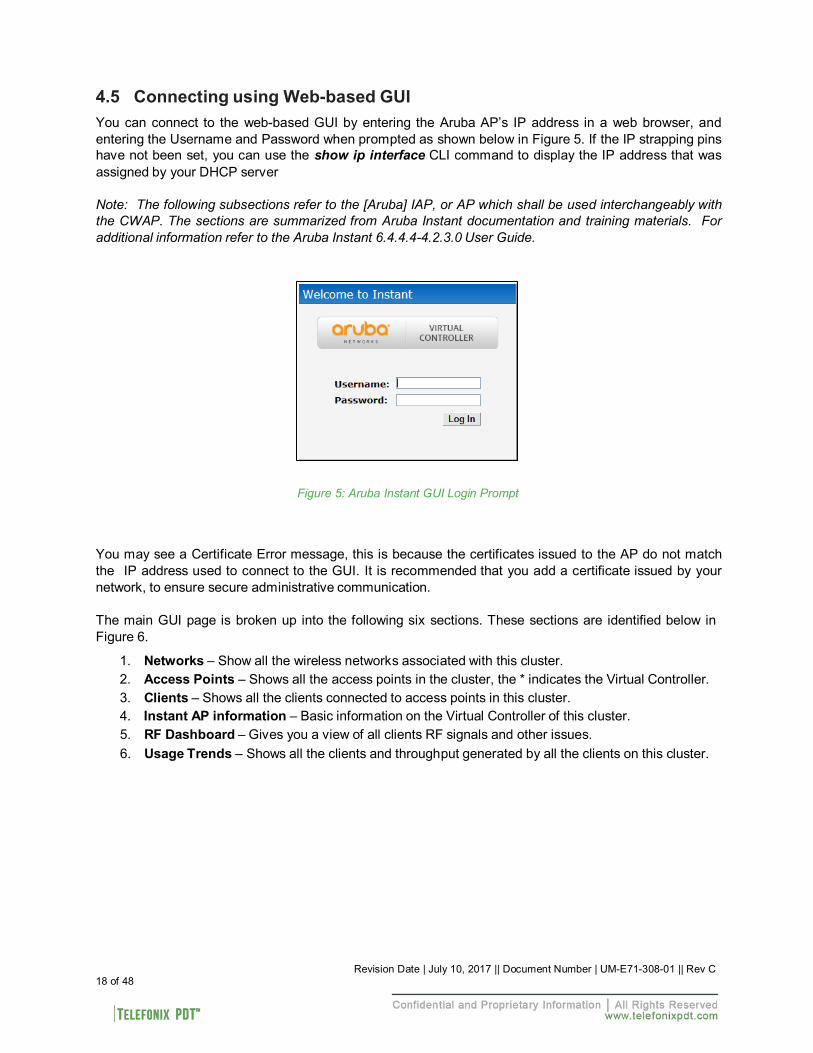
You can connect to the web-based GUI by entering the Aruba AP’s IP address in a web browser, and entering the Username and Password when prompted as shown below in Figure 5. If the IP strapping pins have not been set, you can use the show ip interface CLI command to display the IP address that was assigned by your DHCP server
Note: The following subsections refer to the [Aruba] IAP, or AP which shall be used interchangeably with the CWAP. The sections are summarized from Aruba Instant documentation and training materials. For additional information refer to the Aruba Instant 6.4.4.4-4.2.3.0 User Guide.
Figure 5: Aruba Instant GUI Login Prompt
You may see a Certificate Error message, this is because the certificates issued to the AP do not match the IP address used to connect to the GUI. It is recommended that you add a certificate issued by your network, to ensure secure administrative communication.
The main GUI page is broken up into the following six sections. These sections are identified below in Figure 6.
1. Networks – Show all the wireless networks associated with this cluster. 2. Access Points – Shows all the access points in the cluster, the * indicates the Virtual Controller. 3. Clients – Shows all the clients connected to access points in this cluster. 4. Instant AP information – Basic information on the Virtual Controller of this cluster. 5. RF Dashboard – Gives you a view of all clients RF signals and other issues. 6. Usage Trends – Shows all the clients and throughput generated by all the clients on this cluster.
18 of 48 Revision Date | July 10, 2017 || Document Number | UM-E71-308-01 || Rev C
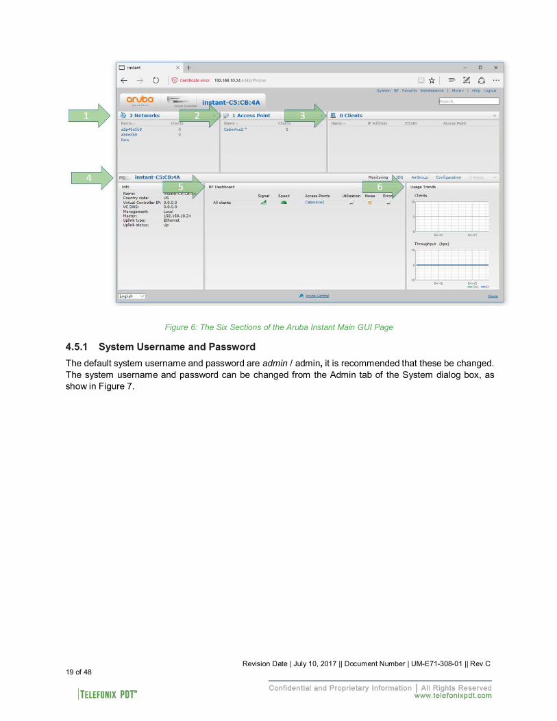
Figure 6: The Six Sections of the Aruba Instant Main GUI Page 4.5.1 System Username and Password
The default system username and password are admin / admin, it is recommended that these be changed. The system username and password can be changed from the Admin tab of the System dialog box, as show in Figure 7.
19 of 48 Revision Date | July 10, 2017 || Document Number | UM-E71-308-01 || Rev C
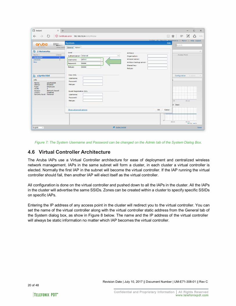
Figure 7: The System Username and Password can be changed on the Admin tab of the System Dialog Box. 4.6 Virtual Controller Architecture
The Aruba IAPs use a Virtual Controller architecture for ease of deployment and centralized wireless network management. IAPs in the same subnet will form a cluster, in each cluster a virtual controller is elected. Normally the first IAP in the subnet will become the virtual controller. If the IAP running the virtual controller should fail, then another IAP will elect itself as the virtual controller.
All configuration is done on the virtual controller and pushed down to all the IAPs in the cluster. All the IAPs in the cluster will advertise the same SSIDs. Zones can be created within a cluster to specify specific SSIDs on specific IAPs.
Entering the IP address of any access point in the cluster will redirect you to the virtual controller. You can set the name of the virtual controller along with the virtual controller static address from the General tab of the System dialog box, as show in Figure 8 below. The name and the IP address of the virtual controller will always be static information no matter which IAP becomes the virtual controller.
20 of 48 Revision Date | July 10, 2017 || Document Number | UM-E71-308-01 || Rev C
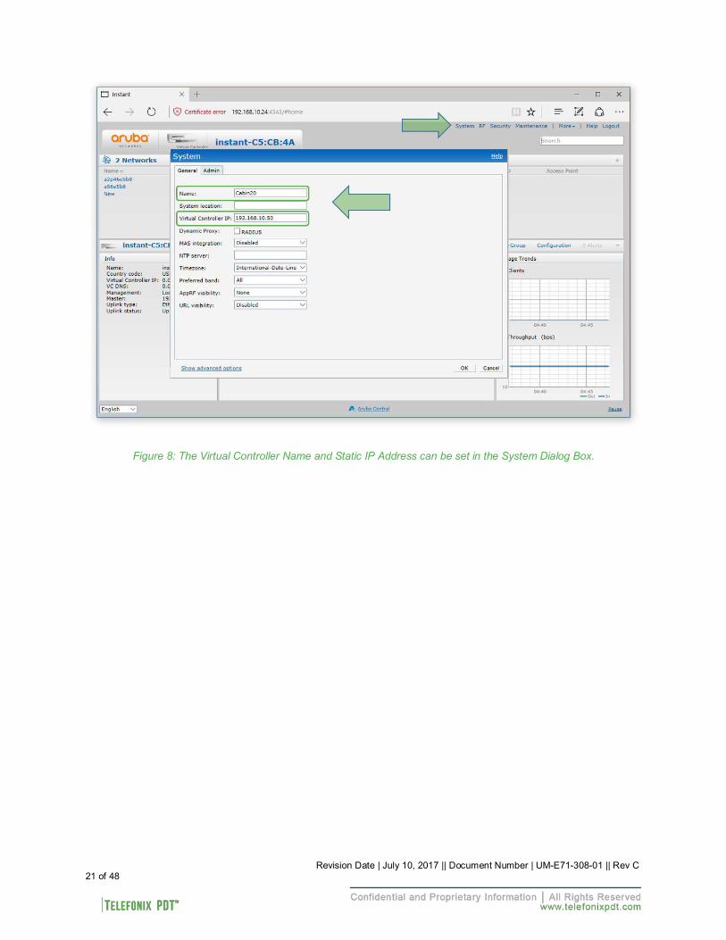
Figure 8: The Virtual Controller Name and Static IP Address can be set in the System Dialog Box.
21 of 48 Revision Date | July 10, 2017 || Document Number | UM-E71-308-01 || Rev C
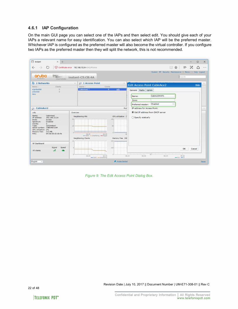
4.6.1 IAP Configuration
On the main GUI page you can select one of the IAPs and then select edit. You should give each of your IAPs a relevant name for easy identification. You can also select which IAP will be the preferred master. Whichever IAP is configured as the preferred master will also become the virtual controller. If you configure two IAPs as the preferred master then they will split the network, this is not recommended.
Figure 9: The Edit Access Point Dialog Box.
22 of 48 Revision Date | July 10, 2017 || Document Number | UM-E71-308-01 || Rev C
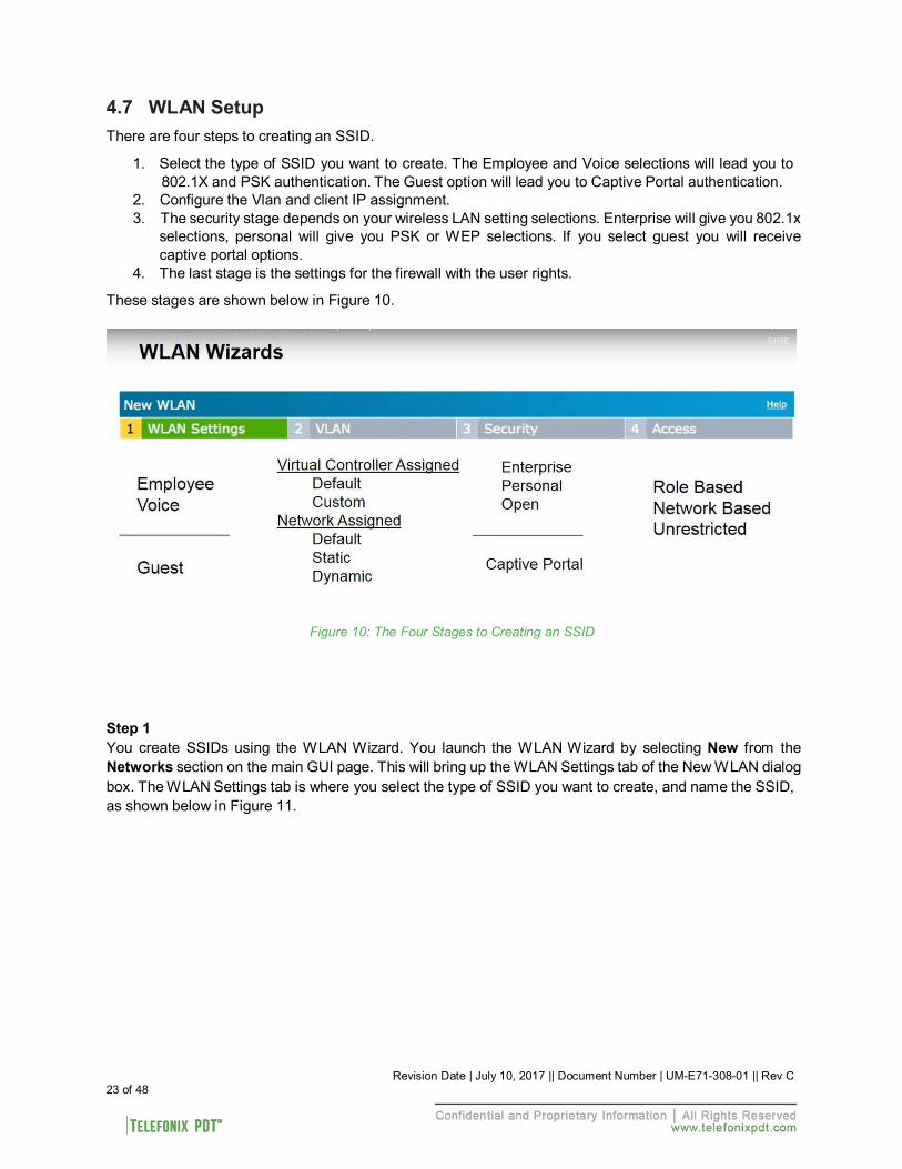
4.7 WLAN Setup
There are four steps to creating an SSID.
1. Select the type of SSID you want to create. The Employee and Voice selections will lead you to 802.1X and PSK authentication. The Guest option will lead you to Captive Portal authentication.
2. Configure the Vlan and client IP assignment. 3. The security stage depends on your wireless LAN setting selections. Enterprise will give you 802.1x
selections, personal will give you PSK or WEP selections. If you select guest you will receive captive portal options.
4. The last stage is the settings for the firewall with the user rights.
These stages are shown below in Figure 10.
Figure 10: The Four Stages to Creating an SSID
Step 1 You create SSIDs using the WLAN Wizard. You launch the WLAN Wizard by selecting New from the Networks section on the main GUI page. This will bring up the WLAN Settings tab of the New WLAN dialog box. The WLAN Settings tab is where you select the type of SSID you want to create, and name the SSID, as shown below in Figure 11.
23 of 48 Revision Date | July 10, 2017 || Document Number | UM-E71-308-01 || Rev C
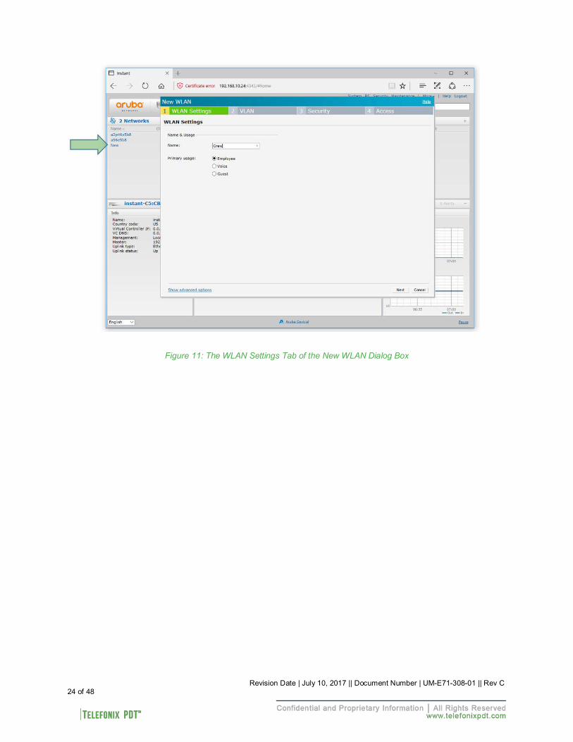
Figure 11: The WLAN Settings Tab of the New WLAN Dialog Box
24 of 48 Revision Date | July 10, 2017 || Document Number | UM-E71-308-01 || Rev C
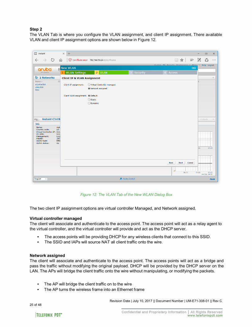
Step 2 The VLAN Tab is where you configure the VLAN assignment, and client IP assignment. There available VLAN and client IP assignment options are shown below in Figure 12.
Figure 12: The VLAN Tab of the New WLAN Dialog Box
The two client IP assignment options are virtual controller Managed, and Network assigned.
Virtual controller managed The client will associate and authenticate to the access point. The access point will act as a relay agent to the virtual controller, and the virtual controller will provide and act as the DHCP server.
• The access points will be providing DHCP for any wireless clients that connect to this SSID. • The SSID and IAPs will source NAT all client traffic onto the wire.
Network assigned The client will associate and authenticate to the access point. The access points will act as a bridge and pass the traffic without modifying the original payload. DHCP will be provided by the DHCP server on the LAN. The APs will bridge the client traffic onto the wire without manipulating, or modifying the packets.
• The AP will bridge the client traffic on to the wire • The AP turns the wireless frame into an Ethernet frame
25 of 48 Revision Date | July 10, 2017 || Document Number | UM-E71-308-01 || Rev C
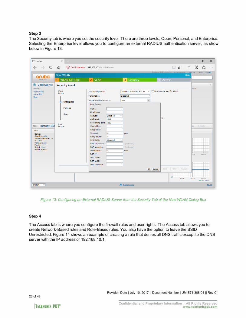
Step 3 The Security tab is where you set the security level. There are three levels, Open, Personal, and Enterprise. Selecting the Enterprise level allows you to configure an external RADIUS authentication server, as show below in Figure 13.
Figure 13: Configuring an External RADIUS Server from the Security Tab of the New WLAN Dialog Box
Step 4
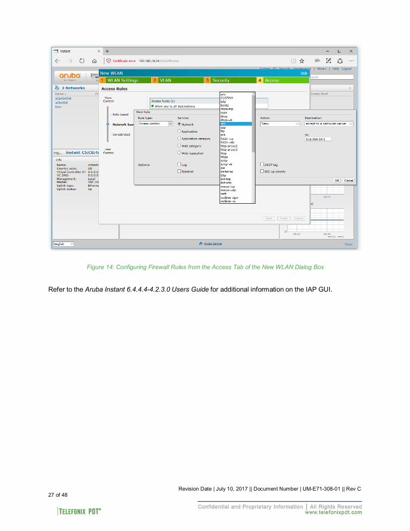
The Access tab is where you configure the firewall rules and user rights. The Access tab allows you to create Network-Based rules and Role-Based rules. You also have the option to leave the SSID Unrestricted. Figure 14 shows an example of creating a rule that denies all DNS traffic except to the DNS server with the IP address of 192.168.10.1.
26 of 48 Revision Date | July 10, 2017 || Document Number | UM-E71-308-01 || Rev C
Revision Date | July 10, 2017 || Document Number | UM-E71-308-01 || Rev C 27 of 48
Figure 14: Configuring Firewall Rules from the Access Tab of the New WLAN Dialog Box
Refer to the Aruba Instant 6.4.4.4-4.2.3.0 Users Guide for additional information on the IAP GUI.
Revision Date | July 10, 2017 || Document Number | UM-E71-308-01 || Rev C 28 of 48
5 Physical I/O
5.1 Connections and Cabling
Table 6 lists the CWAP’s external connector Interfaces (per ARINC 628).
Table 6: CWAP External Connector Interfaces
Ref Des. Shell Insert Mating Shell Mating Insert
J1 EN4165M01AA EN4165A20-22-1NA EN4165M61AA EN4165A20-22-1NB J2 EN4165M01AB EN4165A20-22-1NB EN4165M61AB EN4165A20-22-1NA J3 EN4165M01AC EN4165A20-22-1NA EN4165M61AC EN4165A20-22-1NB
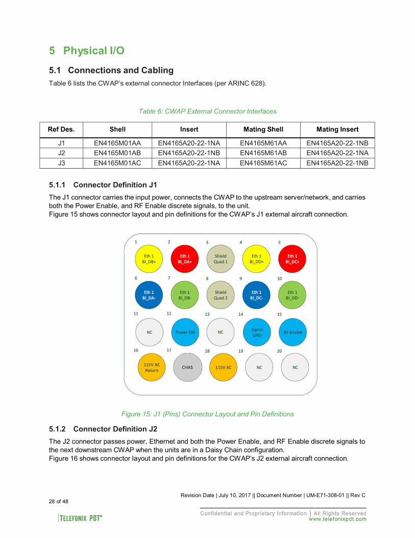
5.1.1 Connector Definition J1
The J1 connector carries the input power, connects the CWAP to the upstream server/network, and carries both the Power Enable, and RF Enable discrete signals, to the unit. Figure 15 shows connector layout and pin definitions for the CWAP’s J1 external aircraft connection.
Figure 15: J1 (Pins) Connector Layout and Pin Definitions
5.1.2 Connector Definition J2
The J2 connector passes power, Ethernet and both the Power Enable, and RF Enable discrete signals to the next downstream CWAP when the units are in a Daisy Chain configuration. Figure 16 shows connector layout and pin definitions for the CWAP’s J2 external aircraft connection.
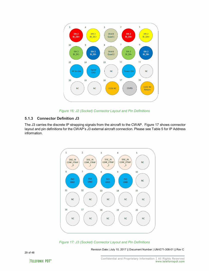
Revision Date | July 10, 2017 || Document Number | UM-E71-308-01 || Rev C 29 of 48
Figure 16: J2 (Socket) Connector Layout and Pin Definitions 5.1.3 Connector Definition J3
The J3 carries the discrete IP strapping signals from the aircraft to the CWAP. Figure 17 shows connector layout and pin definitions for the CWAP’s J3 external aircraft connection. Please see Table 5 for IP Address information.
Figure 17: J3 (Socket) Connector Layout and Pin Definitions
5.2 Maintenance Connectors
Two maintenance connectors are located on the front of the unit behind the maintenance door.
5.2.1 Connector Definition J10 USB 2.0 connector
The J10 connector is a female micro USB that provides a serial interface to both the SIB and the AP.
5.2.2 Programming Header
A four pin SIB programming header is located below the J10 connector. This programming header provides an interface for programming the SIB bootloader.
5.2.3 Reset button
The reset button is located behind the maintenance door. Holding the reset button for 5 seconds, until the power LED rapidly blinks, will factory reset the Aruba AP.
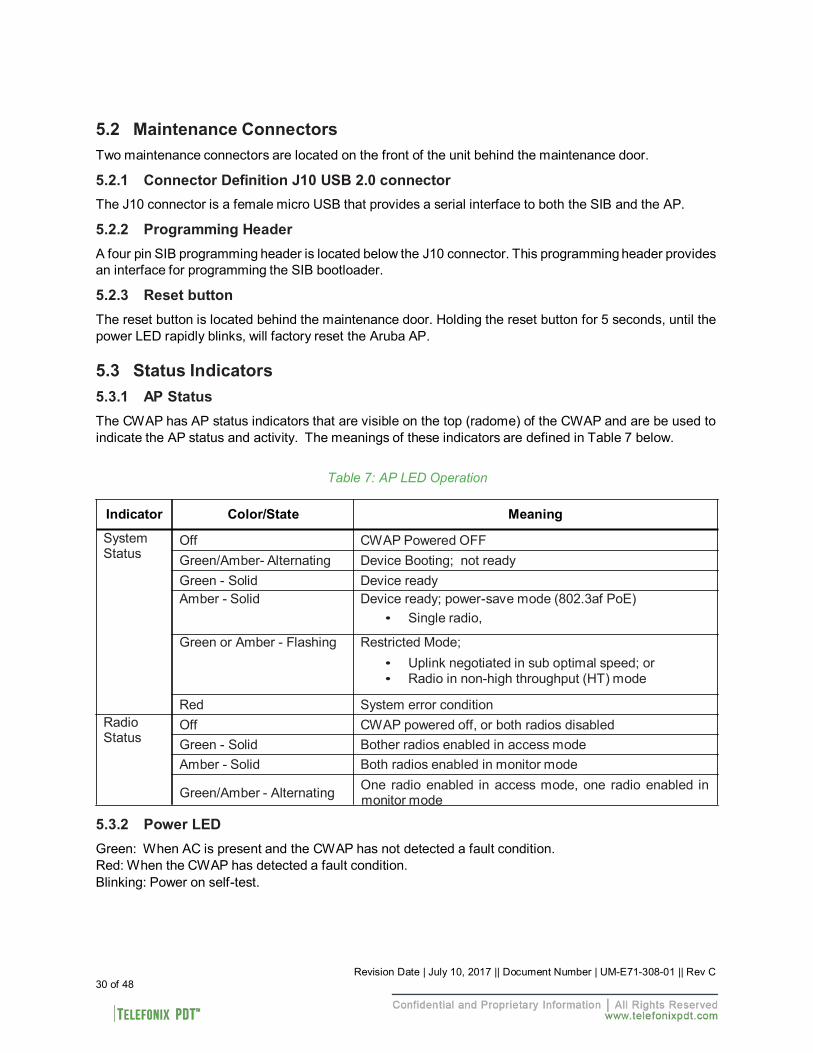
5.3 Status Indicators
5.3.1 AP Status
The CWAP has AP status indicators that are visible on the top (radome) of the CWAP and are be used to indicate the AP status and activity. The meanings of these indicators are defined in Table 7 below.
Table 7: AP LED Operation
Indicator Color/State Meaning
System Status
Radio Status
Off CWAP Powered OFF Green/Amber- Alternating Device Booting; not ready Green - Solid Device ready Amber - Solid Device ready; power-save mode (802.3af PoE)
• Single radio,
Green or Amber - Flashing Restricted Mode; • Uplink negotiated in sub optimal speed; or • Radio in non-high throughput (HT) mode
Red System error condition Off CWAP powered off, or both radios disabled Green - Solid Bother radios enabled in access mode Amber - Solid Both radios enabled in monitor mode
Green/Amber - Alternating One radio enabled in access mode, one radio enabled in monitor mode
5.3.2 Power LED
Green: When AC is present and the CWAP has not detected a fault condition. Red: When the CWAP has detected a fault condition. Blinking: Power on self-test.
30 of 48 Revision Date | July 10, 2017 || Document Number | UM-E71-308-01 || Rev C
Revision Date | July 10, 2017 || Document Number | UM-E71-308-01 || Rev C 31 of 48
5.3.3 Link LEDs
The CWAP includes two Link LEDs visible on the front panel. The LEDs indicate Ethernet activity on either LAN 1 (J1 connector) or LAN 2 (J2 connector).
(Intentionally Left Blank)
Revision Date | July 10, 2017 || Document Number | UM-E71-308-01 || Rev C 32 of 48
6 Performance Data
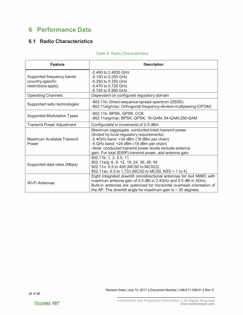
6.1 Radio Characteristics
Table 8: Radio Characteristics
Feature
Description
Supported frequency bands (country-specific restrictions apply)
-2.400 to 2.4835 GHz -5.150 to 5.250 GHz -5.250 to 5.350 GHz -5.470 to 5.725 GHz -5.725 to 5.850 GHz
Operating Channels Dependent on configured regulatory domain Supported radio technologies -802.11b: Direct-sequence spread-spectrum (DSSS)
-802.11a/g/n/ac: Orthogonal frequency-division multiplexing (OFDM) Supported Modulation Types -802.11b: BPSK, QPSK, CCK
-802.11a/g/n/ac: BPSK, QPSK, 16-QAM, 64-QAM,256-QAM Transmit Power Adjustment Configurable in increments of 0.5 dBm
Maximum Available Transmit Power
Maximum (aggregate, conducted total) transmit power (limited by local regulatory requirements): -2.4GHz band: +24 dBm (18 dBm per chain) -5 GHz band: +24 dBm (18 dBm per chain) -Note: conducted transmit power levels exclude antenna gain. For total (EIRP) transmit power, add antenna gain
Supported data rates (Mbps)
802.11b: 1, 2, 5.5, 11 802.11a/g: 6, 9, 12, 18, 24, 36, 48, 54 802.11n: 6.5 to 450 (MCS0 to MCS23) 802.11ac: 6.5 to 1,733 (MCS0 to MCS9, NSS = 1 to 4)
Wi-Fi Antennas
Eight integrated downtilt omnidirectional antennas for 4x4 MIMO with maximum antenna gain of 4.0 dBi in 2.4GHz and 5.5 dBi in 5GHz. Built-in antennas are optimized for horizontal overhead orientation of the AP. The downtilt angle for maximum gain is ~ 30 degrees.
Revision Date | July 10, 2017 || Document Number | UM-E71-308-01 || Rev C 33 of 48
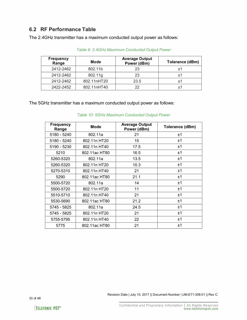
6.2 RF Performance Table
The 2.4GHz transmitter has a maximum conducted output power as follows:
Table 9: 2.4GHz Maximum Conducted Output Power
Frequency Range
Mode Average Output
Power (dBm)
Tolerance (dBm) 2412-2462 802.11b 23 ±1 2412-2462 802.11g 23 ±1 2412-2462 802.11nHT20 23.5 ±1 2422-2452 802.11nHT40 22 ±1
The 5GHz transmitter has a maximum conducted output power as follows:
Table 10: 5GHz Maximum Conducted Output Power
Frequency Range Mode Average Output
Power (dBm) Tolerance (dBm)
5180 - 5240 802.11a 21 ±1 5180 - 5240 802.11n HT20 15 ±1 5190 - 5230 802.11n HT40 17.5 ±1
5210 802.11ac HT80 16.5 ±1 5260-5320 802.11a 13.5 ±1 5260-5320 802.11n HT20 10.3 ±1 5270-5310 802.11n HT40 21 ±1
5290 802.11ac HT80 21.1 ±1 5500-5720 802.11a 14 ±1 5500-5720 802.11n HT20 11 ±1 5510-5710 802.11n HT40 21 ±1 5530-5690 802.11ac HT80 21.2 ±1 5745 - 5825 802.11a 24.5 ±1 5745 - 5825 802.11n HT20 21 ±1 5755-5795 802.11n HT40 22 ±1
5775 802.11ac HT80 21 ±1
Revision Date | July 10, 2017 || Document Number | UM-E71-308-01 || Rev C 34 of 48
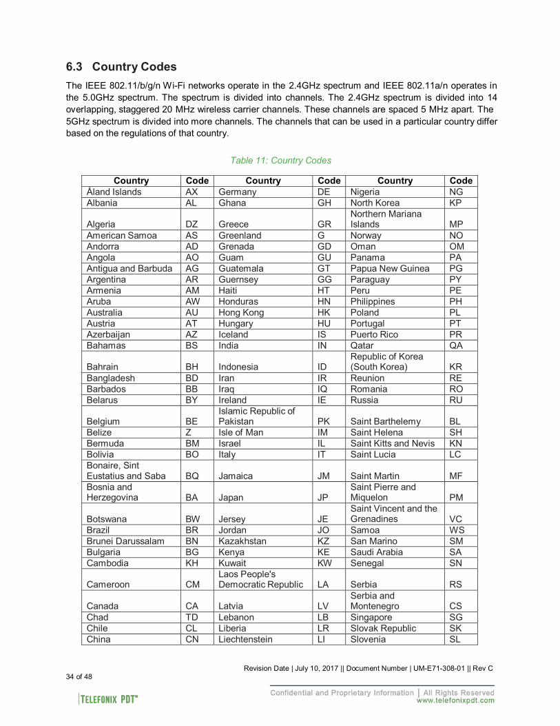
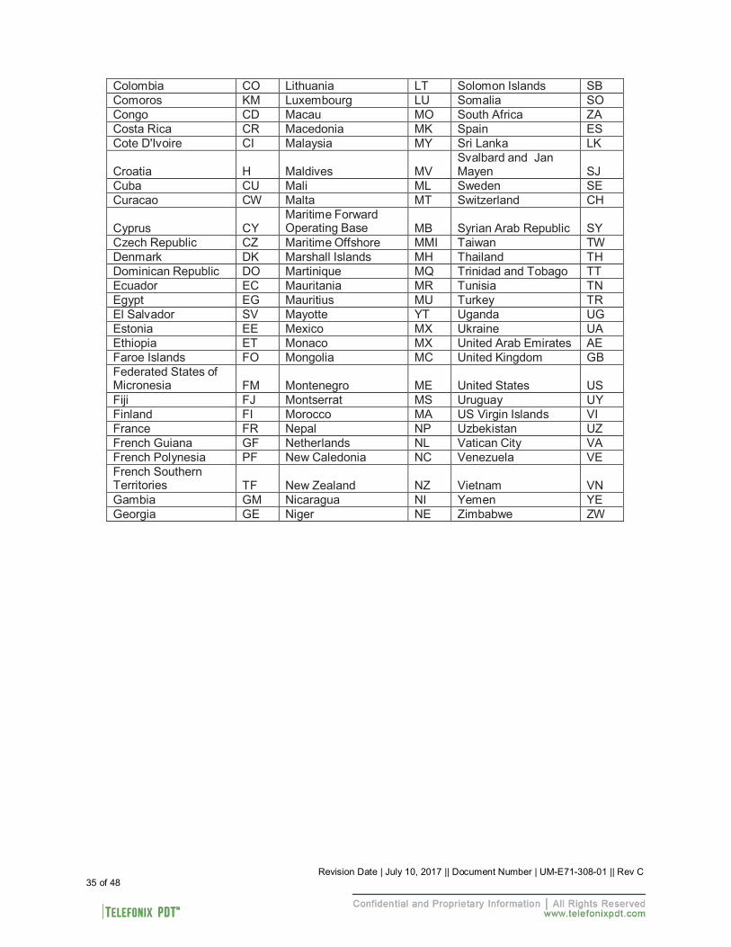
6.3 Country Codes
The IEEE 802.11/b/g/n Wi-Fi networks operate in the 2.4GHz spectrum and IEEE 802.11a/n operates in the 5.0GHz spectrum. The spectrum is divided into channels. The 2.4GHz spectrum is divided into 14 overlapping, staggered 20 MHz wireless carrier channels. These channels are spaced 5 MHz apart. The 5GHz spectrum is divided into more channels. The channels that can be used in a particular country differ based on the regulations of that country.
Table 11: Country Codes
Country Code Country Code Country Code Åland Islands AX Germany DE Nigeria NG Albania AL Ghana GH North Korea KP
Algeria
DZ
Greece
GR
Northern Mariana Islands
MP
American Samoa AS Greenland G Norway NO Andorra AD Grenada GD Oman OM Angola AO Guam GU Panama PA Antigua and Barbuda AG Guatemala GT Papua New Guinea PG Argentina AR Guernsey GG Paraguay PY Armenia AM Haiti HT Peru PE Aruba AW Honduras HN Philippines PH Australia AU Hong Kong HK Poland PL Austria AT Hungary HU Portugal PT Azerbaijan AZ Iceland IS Puerto Rico PR Bahamas BS India IN Qatar QA
Bahrain
BH
Indonesia
ID
Republic of Korea (South Korea)
KR
Bangladesh BD Iran IR Reunion RE Barbados BB Iraq IQ Romania RO Belarus BY Ireland IE Russia RU
Belgium
BE
Islamic Republic of Pakistan
PK
Saint Barthelemy
BL
Belize Z Isle of Man IM Saint Helena SH Bermuda BM Israel IL Saint Kitts and Nevis KN Bolivia BO Italy IT Saint Lucia LC Bonaire, Sint Eustatius and Saba
BQ
Jamaica
JM
Saint Martin
MF
Bosnia and Herzegovina
BA
Japan
JP
Saint Pierre and Miquelon
PM
Botswana
BW
Jersey
JE
Saint Vincent and the Grenadines
VC
Brazil BR Jordan JO Samoa WS Brunei Darussalam BN Kazakhstan KZ San Marino SM Bulgaria BG Kenya KE Saudi Arabia SA Cambodia KH Kuwait KW Senegal SN
Cameroon
CM
Laos People's Democratic Republic
LA
Serbia
RS
Canada
CA
Latvia
LV
Serbia and Montenegro
CS
Chad TD Lebanon LB Singapore SG Chile CL Liberia LR Slovak Republic SK China CN Liechtenstein LI Slovenia SL
Revision Date | July 10, 2017 || Document Number | UM-E71-308-01 || Rev C 35 of 48
Colombia CO Lithuania LT Solomon Islands SB Comoros KM Luxembourg LU Somalia SO Congo CD Macau MO South Africa ZA Costa Rica CR Macedonia MK Spain ES Cote D'Ivoire CI Malaysia MY Sri Lanka LK
Croatia
H
Maldives
MV
Svalbard and Jan Mayen
SJ
Cuba CU Mali ML Sweden SE Curacao CW Malta MT Switzerland CH
Cyprus
CY
Maritime Forward Operating Base
MB
Syrian Arab Republic
SY
Czech Republic CZ Maritime Offshore MMI Taiwan TW Denmark DK Marshall Islands MH Thailand TH Dominican Republic DO Martinique MQ Trinidad and Tobago TT Ecuador EC Mauritania MR Tunisia TN Egypt EG Mauritius MU Turkey TR El Salvador SV Mayotte YT Uganda UG Estonia EE Mexico MX Ukraine UA Ethiopia ET Monaco MX United Arab Emirates AE Faroe Islands FO Mongolia MC United Kingdom GB Federated States of Micronesia
FM
Montenegro
ME
United States
US
Fiji FJ Montserrat MS Uruguay UY Finland FI Morocco MA US Virgin Islands VI France FR Nepal NP Uzbekistan UZ French Guiana GF Netherlands NL Vatican City VA French Polynesia PF New Caledonia NC Venezuela VE French Southern Territories
TF
New Zealand
NZ
Vietnam
VN
Gambia GM Nicaragua NI Yemen YE Georgia GE Niger NE Zimbabwe ZW
Revision Date | July 10, 2017 || Document Number | UM-E71-308-01 || Rev C 36 of 48
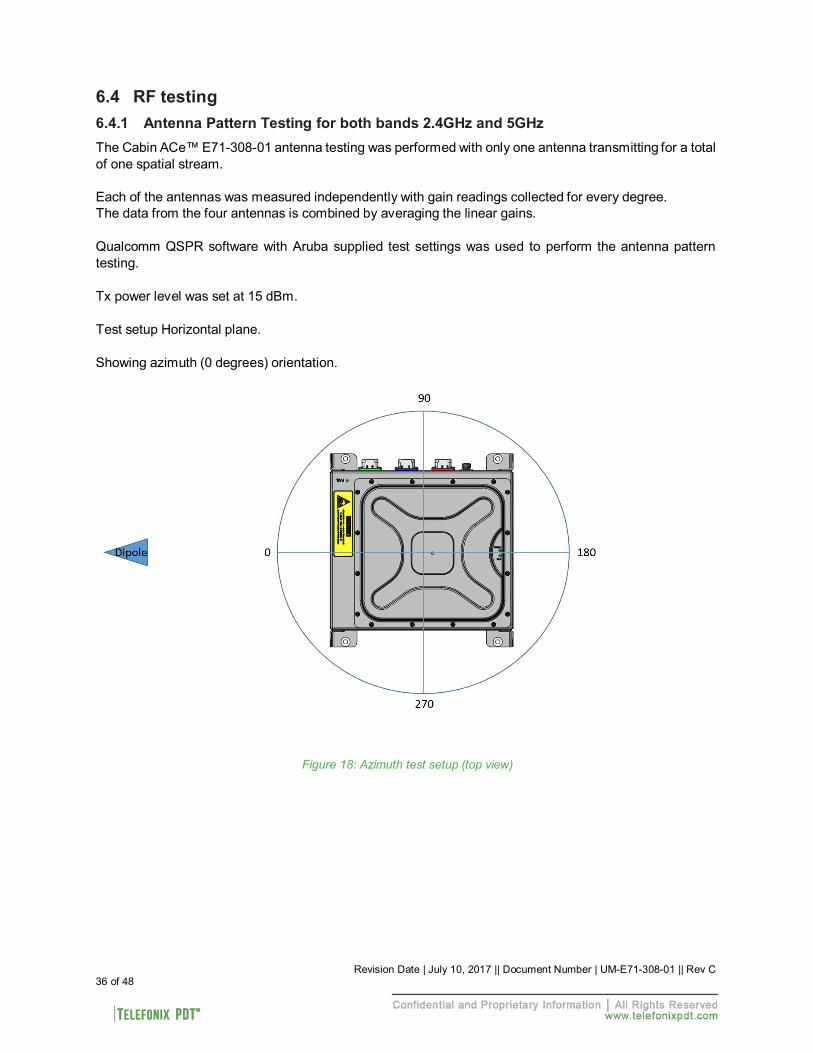
6.4 RF testing
6.4.1 Antenna Pattern Testing for both bands 2.4GHz and 5GHz
The Cabin ACe™ E71-308-01 antenna testing was performed with only one antenna transmitting for a total of one spatial stream.
Each of the antennas was measured independently with gain readings collected for every degree. The data from the four antennas is combined by averaging the linear gains.
Qualcomm QSPR software with Aruba supplied test settings was used to perform the antenna pattern testing.
Tx power level was set at 15 dBm.
Test setup Horizontal plane.
Showing azimuth (0 degrees) orientation.
Figure 18: Azimuth test setup (top view)
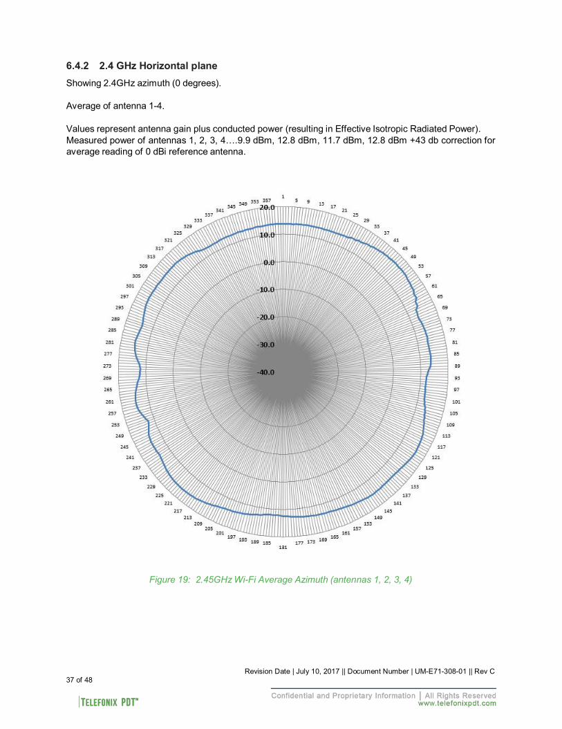
6.4.2 2.4 GHz Horizontal plane
Showing 2.4GHz azimuth (0 degrees).
Average of antenna 1-4.
Values represent antenna gain plus conducted power (resulting in Effective Isotropic Radiated Power). Measured power of antennas 1, 2, 3, 4….9.9 dBm, 12.8 dBm, 11.7 dBm, 12.8 dBm +43 db correction for average reading of 0 dBi reference antenna.
Figure 19: 2.45GHz Wi-Fi Average Azimuth (antennas 1, 2, 3, 4)
37 of 48 Revision Date | July 10, 2017 || Document Number | UM-E71-308-01 || Rev C
Revision Date | July 10, 2017 || Document Number | UM-E71-308-01 || Rev C 38 of 48
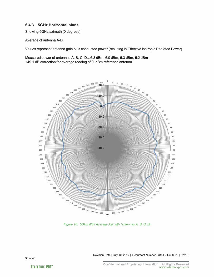
6.4.3 5GHz Horizontal plane
Showing 5GHz azimuth (0 degrees)
Average of antenna A-D.
Values represent antenna gain plus conducted power (resulting in Effective Isotropic Radiated Power).
Measured power of antennas A, B, C, D…6.8 dBm, 6.0 dBm, 5.3 dBm, 5.2 dBm +49.1 dB correction for average reading of 0 dBm reference antenna.
Figure 20: 5GHz WiFi Average Azimuth (antennas A, B, C, D)
Revision Date | July 10, 2017 || Document Number | UM-E71-308-01 || Rev C 39 of 48
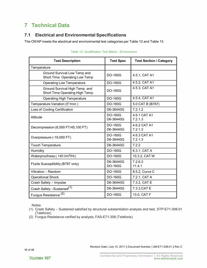
7 Technical Data 7.1 Electrical and Environmental Specifications
The CWAP meets the electrical and environmental test categories per Table 12 and Table 13.
Table 12: Qualification Test Matrix - Environment
Test Description Test Spec Test Section / Category
Temperature Ground Survival Low Temp and Short Time Operating Low Temp
DO-160G
4.5.1, CAT A1
Operating Low Temperature DO-160G 4.5.2, CAT A1
Ground Survival High Temp. and Short Time Operating High Temp.
DO-160G
4.5.3, CAT A1
Operating High Temperature DO-160G 4.5.4, CAT A1
Temperature Variation (5°/min ) DO-160G 5.0 CAT B (B787) Loss of Cooling Certification D6-36440G 7.2.1.2
Altitude DO-160G
D6-36440G 4.6.1 CAT A1 7.2.1.3
Decompression (6,000 FT/45,100 FT) DO-160G
D6-36440G 4.6.2 CAT A1 7.2.1.3
Overpressure (-19,000 FT) DO-160G
D6-36440G 4.6.3 CAT A1 7.2.1.3
Touch Temperature D6-36440G 7.2.2 Humidity DO-160G 6.3.1, CAT A Waterproofness ( 140 l/m2/Hr) DO-160G 10.3.2, CAT W
Fluids Susceptibility (B787 only) D6-36440G
DO-160G 7.2.6.3 11.4.1
Vibration – Random DO-160G 8.5.2, Curve C Operational Shock DO-160G 7.2.1, CAT A Crash Safety – Impulse D6-36440G 7.3.2, CAT E
Crash Safety –Sustained(1) D6-36440G 7.3.3,CAT E
Fungus Resistance (2) DO-160G 13.0, CAT F
Notes:
(1) Crash Safety – Sustained satisfied by structural substantiation analysis and test, STP-E71-308-01 (Telefonix)
(2) Fungus Resistance verified by analysis, FAS-E71-308 (Telefonix)
Revision Date | July 10, 2017 || Document Number | UM-E71-308-01 || Rev C 40 of 48
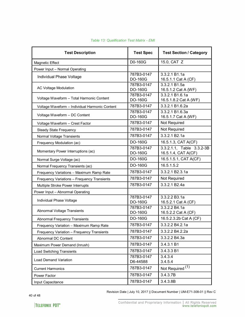
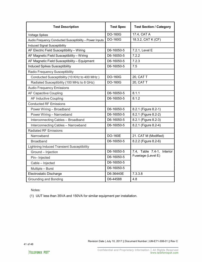
Table 13: Qualification Test Matrix - EMI
Test Description
Test Spec
Test Section / Category
Magnetic Effect D0-160G 15.0, CAT Z
Power Input – Normal Operating
Individual Phase Voltage 787B3-0147 DO-160G
3.3.2.1 B1.1a 16.5.1.1 Cat A (CF)
AC Voltage Modulation
787B3-0147 DO-160G
3.3.2.1 B1.5a 16.5.1.2 Cat A (WF)
Voltage Waveform – Total Harmonic Content
787B3-0147 DO-160G
3.3.2.1 B1.6.1a 16.5.1.8.2 Cat A (WF)
Voltage Waveform – Individual Harmonic Content 787B3-0147 3.3.2.1 B1.6.2a
Voltage Waveform – DC Content 787B3-0147 DO-160G
3.3.2.1 B1.6.3a 16.5.1.7 Cat A (WF)
Voltage Waveform – Crest Factor 787B3-0147 Not Required
Steady State Frequency 787B3-0147 Not Required
Normal Voltage Transients 787B3-0147 3.3.2.1 B2.1a
Frequency Modulation (ac) DO-160G 16.5.1.3, CAT A(CF)
Momentary Power Interruptions (ac) 787B3-0147 DO-160G
3.3.2.1.1, Table 3.3.2-3B 16.5.1.4, CAT A(CF)
Normal Surge Voltage (ac) DO-160G 16.5.1.5.1, CAT A(CF)
Normal Frequency Transients (ac) DO-160G 16.5.1.5.2
Frequency Variations – Maximum Ramp Rate 787B3-0147 3.3.2.1 B2.3.1a
Frequency Variations – Frequency Transients 787B3-0147 Not Required
Multiple Stroke Power Interrupts 787B3-0147 3.3.2.1 B2.4a
Power Input – Abnormal Operating
Individual Phase Voltage 787B3-0147 DO-160G
3.3.2.2 B3.1a 16.5.2.1 Cat A (CF)
Abnormal Voltage Transients
787B3-0147 DO-160G
3.3.2.2 B4.1a 16.5.2.2 Cat A (CF)
Abnormal Frequency Transients DO-160G 16.5.2.3.2b Cat A (CF)
Frequency Variation – Maximum Ramp Rate 787B3-0147 3.3.2.2 B4.2.1a
Frequency Variation – Frequency Transients 787B3-0147 3.3.2.2 B4.2.2a
Abnormal DC Content 787B3-0147 3.3.2.2 B4.3a
Maximum Power Demand (Inrush) 787B3-0147 3.4.3.1 B1
Load Switching Transients 787B3-0147 3.4.3.3 B1 Load Demand Variation
787B3-0147 D6-44588
3.4.3.4 3.4.5.4
Current Harmonics 787B3-0147 Not Required (1)
Power Factor 787B3-0147 3.4.3.7B
Input Capacitance 787B3-0147 3.4.3.8B
Revision Date | July 10, 2017 || Document Number | UM-E71-308-01 || Rev C 41 of 48
Test Description
Test Spec
Test Section / Category
Voltage Spikes DO-160G 17.4, CAT A
Audio Frequency Conducted Susceptibility – Power Inputs DO-160G 18.3.2, CAT K (CF)
Induced Signal Susceptibility AF Electric Field Susceptibility – Wiring D6-16050-5 7.2.1, Level E AF Magnetic Field Susceptibility – Wiring D6-16050-5 7.2.2 AF Magnetic Field Susceptibility – Equipment D6-16050-5 7.2.3 Induced Spikes Susceptibility D6-16050-5 7.5
Radio Frequency Susceptibility Conducted Susceptibility (10 KHz to 400 MHz ) DO-160G 20, CAT T Radiated Susceptibility (100 MHz to 8 GHz) DO-160G 20, CAT T
Audio Frequency Emissions AF Capacitive Coupling D6-16050-5 8.1.1
AF Inductive Coupling D6-16050-5 8.1.2 Conducted RF Emissions
Power Wiring – Broadband D6-16050-5 8.2.1 (Figure 8.2-1) Power Wiring – Narrowband D6-16050-5 8.2.1 (Figure 8.2-2) Interconnecting Cables – Broadband D6-16050-5 8.2.1 (Figure 8.2-3) Interconnecting Cables – Narrowband D6-16050-5 8.2.1 (Figure 8.2-4)
Radiated RF Emissions Narrowband DO-160E 21. CAT M (Modified) Broadband D6-16050-5 8.2.2 (Figure 8.2-6)
Lightning Induced Transient Susceptibility Ground – Injection D6-16050-5 7.4, Table 7.4-1, Interior
Fuselage (Level E) Pin– Injected D6-16050-5
Cable – Injected D6-16050-5
Multiple – Burst D6-16050-5
Electrostatic Discharge D6-36440E 7.3.3.8 Grounding and Bonding D6-44588 4.8
Notes:
(1) UUT less than 35VA and 150VA for similar equipment per installation.
Revision Date | July 10, 2017 || Document Number | UM-E71-308-01 || Rev C 42 of 48
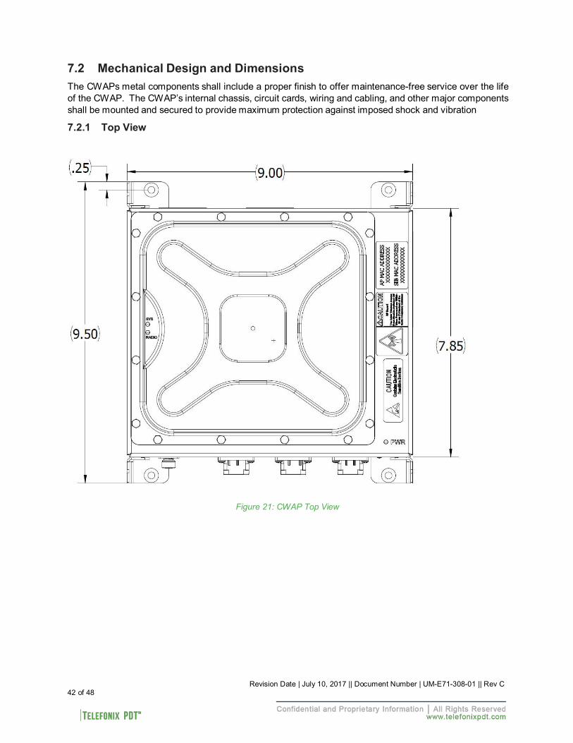
7.2 Mechanical Design and Dimensions
The CWAPs metal components shall include a proper finish to offer maintenance-free service over the life of the CWAP. The CWAP’s internal chassis, circuit cards, wiring and cabling, and other major components shall be mounted and secured to provide maximum protection against imposed shock and vibration
7.2.1 Top View
Figure 21: CWAP Top View
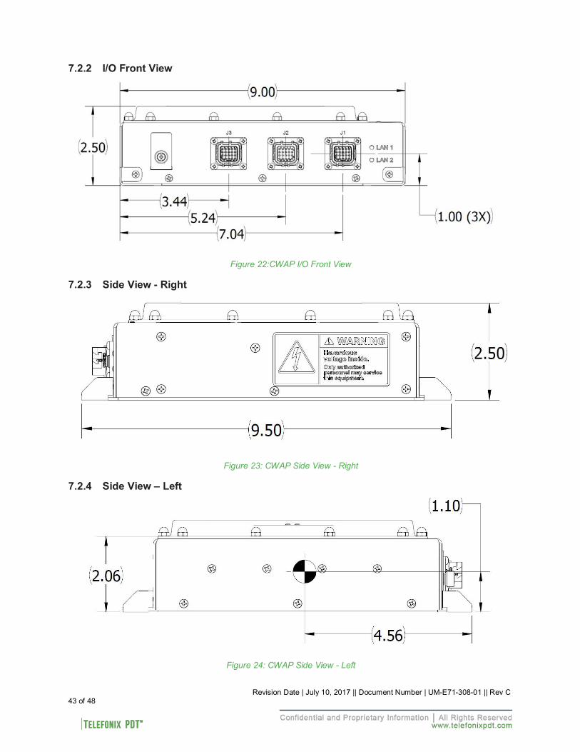
7.2.2 I/O Front View
Figure 22:CWAP I/O Front View
7.2.3 Side View - Right
Figure 23: CWAP Side View - Right
7.2.4 Side View – Left
Figure 24: CWAP Side View - Left
43 of 48 Revision Date | July 10, 2017 || Document Number | UM-E71-308-01 || Rev C
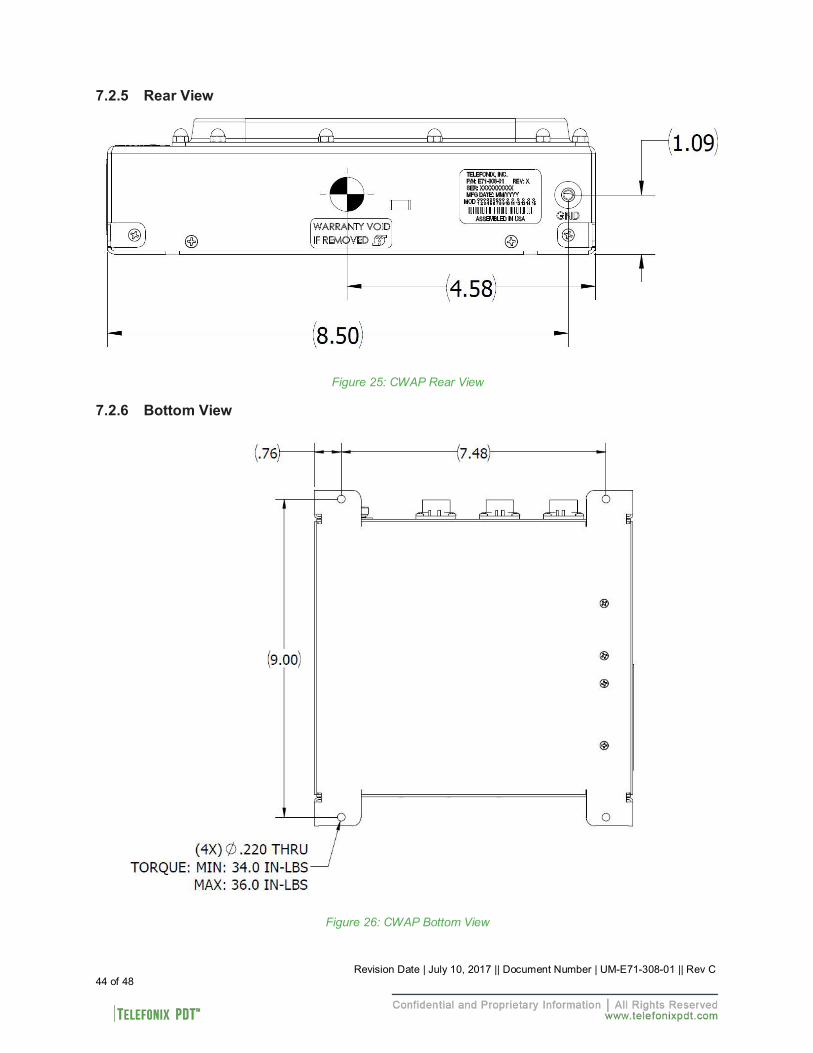
7.2.5 Rear View
Figure 25: CWAP Rear View
7.2.6 Bottom View
Figure 26: CWAP Bottom View
44 of 48 Revision Date | July 10, 2017 || Document Number | UM-E71-308-01 || Rev C
7.2.7 Product Identification
The Part Number Identification Label for each CWAP LRU is located on the rear panel and contains the following information as shown in Figure 25.
7.2.8 Finish and Color
The paint color of the CWAP is medium texture black. The bottom surface of the mounting plate is unpainted and contains a clear, RoHS compliant coating per MIL-DTL-5541, Type II, Class 3. The unpainted surface is provided for bonding of the CWAP enclosure to the aircraft airframe.
7.2.9 Materials
All materials used in the construction of the CWAP are inherently non-nutrient to fungus and do not support combustion. The materials are of the best commercial quality, and will not blister, corrode, crack, soften, or show other immediate latten defects that affect the storage, operation, or environmental capabilities of the unit after any or all of the test specified.
Materials used in the CWAP have been selected in accordance with the appropriate flammability requirements of Code of Federal Regulations FAR-25.853a.
7.2.10 Weight
The CWAP weighs 3.66 lbs.
7.2.11 Cooling Characteristics
The CWAP is designed with passive cooling. • Operational Power Dissipation: 20.0 W Max • Operational Power Dissipation: 13.5 W Nominal
7.2.12 Installation limitations
The CWAP is intended to be installed in the crown of the cabin to provide adequate RF coverage of the WiFi signal. An installation where there is a potential for falling water requires a drip shield. Installations per ARINC 628 part 7 (Stand Alone) shall always have the minimum air gap spacing as follows:
• Bottom (G1) = 0.00” • Left (G2) = 1.00” • Right (G3) = 1.00” • Top (G4) = 1.00” • Front (G5) = 3.00” • Rear (G6) = 1.00”
Installations violating the above air gap spacing must be approved by Telefonix PDT engineering.
There are no minimum installation distances between CWAPs. The maximum distance shall be determined by aircraft type and configuration and content, e.g. throughput considerations.
Radiation Hazard: Maintain a safe distance when in operation. The device should be installed to provide a minimum distance of 27cm to nearby persons while in operation. Remove power if working within these distances.
45 of 48 Revision Date | July 10, 2017 || Document Number | UM-E71-308-01 || Rev C
7.3 Grounding and Bonding
Electrical grounding and bonding of the CWAP unit follow standard avionics industry design practices, ensuring proper grounding for electrical safety and for Electromagnetic Interference (EMI) control and compliance.
7.4 Workmanship
Workmanship, including ANSI/IPC-A-620 soldering, is designed to meet ANSI/J-STD-002 and RTCA/DO- 254.
7.5 Safety
The CWAP is designed to meet the safety requirements of RTCA/DO-254. 7.6 Protective Devices
The CWAP contains a power line fuse that provides electrical separation between the airplane AC power and the CWAP system in the event of a circuit upset per the recommendations of RTCA/DO-254. All input/output signals within the CWAP contains ESD (TVS) protective Diodes and/or isolation transformers that will provide protection from external noise/ESD/lightning. The protection devices have fail-safe features, ensuring that any failure does not create hazardous condition to the CWAP.
The CWAP has a dual output temperature sensor to protect the internal electronics from an over- temperature or under-temperature condition. Additionally, a separate temperature sensor is in place to enable/disable the unit based on low ambient temperatures (below -20ºC).
46 of 48 Revision Date | July 10, 2017 || Document Number | UM-E71-308-01 || Rev C
Revision Date | July 10, 2017 || Document Number | UM-E71-308-01 || Rev C 47 of 48
8 Reliability and Maintainability 8.1 Reliability
The Mean Time Between Failure (MTBF) for the CWAP is a minimum of 200,000 operating hours calculated using the RIAC 217+ (AIC, +30°C, 65% duty cycle, 1428 cycles per year).
8.2 Maintainability
The CWAP is considered an LRU and is repairable only by Telefonix PDT or an authorized repair facility. Periodic maintenance of the CWAP is not required.
8.3 Mean Time to Repair (MTTR)
Repair time will not exceed 30 minutes, which entails replacement of the LRU. 8.4 Failure Detection and Fault Isolation
LED indicators located on the system enclosure provide functional status of the CWAP. 8.5 Production Testing
Production units are subjected to Environmental Stress Screening (ESS), and a production Acceptance Test Procedure (ATP) prior to shipment. These tests are intended to ensure that all elements of the product are functional and capable of performing at both high and low temperature extremes and that they are free of manufacturing defects. The Acceptance Test Procedure is run pre- and post-ESS to test the functional characteristics of the product.
Revision Date | July 10, 2017 || Document Number | UM-E71-308-01 || Rev C 48 of 48
9 Support and Service
9.1 Technical Support
For technical support, please contact [email protected]
9.2 Returning Defective Equipment
All equipment returned to Telefonix PDT must have a Return Material Authorization (RMA) number assigned exclusively by Telefonix PDT. Telefonix PDT cannot be held responsible for any loss or damage caused to the equipment received without an RMA number. The Buyer accepts responsibility for all freight charges for the return of goods to Telefonix’s designated facility. Telefonix PDT will pay return freight charges back to the Buyer's location in the event that the equipment is repaired or replaced within the warranty period stipulated herewith.
Contact and Delivery Address
Telefonix PDT 2340 Ernie Krueger Circle Waukegan, IL 60087 Attn: RMA number
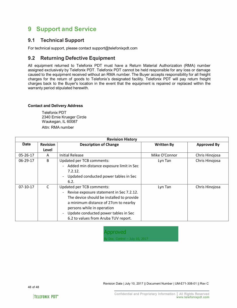
Revision History Date Revision
Level Description of Change Written By Approved By
05-26-17 A Initial Release Mike O'Connor Chris Hinojosa 06-29-17 B Updated per TCB comments:
- Added min distance exposure limit in Sec 7.2.12.
- Updated conducted power tables in Sec 6.2.
Lyn Tan Chris Hinojosa
07-10-17 C Updated per TCB comments: - Revise exposure statement in Sec 7.2.12.
The device should be installed to provide a minimum distance of 27cm to nearby persons while in operation
- Update conducted power tables in Sec 6.2 to values from Aruba TUV report.
Lyn Tan Chris Hinojosa
Approved By Doc. Control – July 10, 2017