Bull ESCALA PL 820Rsupport.bull.com/.../power4/pl820r/g/86Y120EG01/86A120EG01.pdf · Bull ESCALA PL...
196
Bull ESCALA PL 820R User’s Guide 86 A1 20EG 01 ORDER REFERENCE
Transcript of Bull ESCALA PL 820Rsupport.bull.com/.../power4/pl820r/g/86Y120EG01/86A120EG01.pdf · Bull ESCALA PL...

Bull ESCALA PL 820RUser’s Guide
86 A1 20EG 01ORDER REFERENCE


Bull ESCALA PL 820RUser’s Guide
Hardware
June 2003
BULL CEDOC357 AVENUE PATTONB.P.2084549008 ANGERS CEDEX 01FRANCE
86 A1 20EG 01ORDER REFERENCE

The following copyright notice protects this book under the Copyright laws of the United States of Americaand other countries which prohibit such actions as, but not limited to, copying, distributing, modifying, andmaking derivative works.
Copyright Bull S.A. 1992, 2003
Printed in France
Suggestions and criticisms concerning the form, content, and presentation ofthis book are invited. A form is provided at the end of this book for this purpose.
To order additional copies of this book or other Bull Technical Publications, youare invited to use the Ordering Form also provided at the end of this book.
Trademarks and Acknowledgements
We acknowledge the right of proprietors of trademarks mentioned in this book.
AIX� is a registered trademark of International Business Machines Corporation, and is being used underlicence.
UNIX is a registered trademark in the United States of America and other countries licensed exclusively throughthe Open Group.
Linux is a registered trademark of Linus Torvalds.
The information in this document is subject to change without notice. Groupe Bull will not be liable for errorscontained herein, or for incidental or consequential damages in connection with the use of this material.

iiiPreface
Safety Notices
A danger notice indicates the presence of a hazard that has the potential of causing deathor serious personal injury. Danger notices appear on the following pages:
• on page iii
A caution notice indicates the presence of a hazard that has the potential of causingmoderate or minor personal injury. Caution notices appear on the following pages:
• on page iv
• on page 2-7
For a translation of the safety notices contained in this book, see the System Unit SafetyInformation, order number 86 X1 11WD2.
Rack Safety Instructions• Do not install this unit in a rack where the internal rack ambient temperatures will exceed
40 degrees C.
• Do not install this unit in a rack where the air flow is compromised. Any side, front orback of the unit used for air flow through the unit must not be in direct contact with therack.
• Care should be taken to ensure that a hazardous condition is not created due to unevenmechanical loading when installing this unit in a rack. If the rack has a stabilizer it mustbe firmly attached before installing or removing this unit.
• Consideration should be given to the connection of the equipment to the supply circuit sothat overloading of circuits does not compromise the supply wiring or overcurrentprotection. To provide the correct power connection to the rack, refer to the rating labelslocated on the equipment in the rack to determine the total power requirement for thesupply circuit.
• An electrical outlet that is not correctly wired could place hazardous voltage on the metalparts of the system or the devices that attach to the system. It is the responsibility of thecustomer to ensure that the outlet is correctly wired and grounded to prevent anelectrical shock.
Electrical SafetyObserve the following safety instructions anytime you are connecting or disconnectingdevices attached to the workstation.
DANGER!An electrical outlet that is not correctly wired could place hazardous voltage on metalparts of the system or the devices that attach to the system. It is the responsibility ofthe customer to ensure that the outlet is correctly wired and grounded to prevent anelectrical shock.
Before installing or removing signal cables, ensure that the power cables for thesystem unit and all attached devices are unplugged.
When adding or removing any additional devices to or from the system, ensure thatthe power cables for those devices are unplugged before the signal cables are

iv ESCALA PL820R User’s Guide
connected. If possible, disconnect all power cables from the existing system beforeyou add a device.
Use one hand, when possible, to connect or disconnect signal cables to prevent apossible shock from touching two surfaces with different electrical potentials.
During an electrical storm, do not connect cables for display stations, printers,telephones, or station protectors for communications lines.
DANGER!To prevent electrical shock hazard, disconnect all power cables from the electricaloutlet before relocating the system.
Caution:This product is equipped with a three–wire power cable and plug for the user’ssafety. Use this power cable with a properly grounded electrical outlet to avoidelectrical shock.
Caution:This unit has more than one power supply cord. To reduce the risk of electricalshock, disconnect two power supply cords before servicing.
Caution:This unit weighs more than 55 kg (121.2 pounds). Material handling systems such aslevers, slings, or lifts are required to safely move it. When this is not possible,specially trained persons or services (such as riggers or movers) must be used.
Laser Safety InformationCaution:This product may contain a CD–ROM, DVD–ROM, or laser module on a PCI card,which are class 1 laser products.
Laser ComplianceAll lasers are certified in the U.S. to conform to the requirements of DHHS 21 CFRSubchapter J for class 1 laser products. Outside the U.S., they are certified to be incompliance with the IEC 825 (first edition 1984) as a class 1 laser product. Consult the labelon each part for laser certification numbers and approval information.
Caution:All mentioned laser modules are designed so that there is never any human accessto laser radiation above a class 1 level during normal operation, user maintenance, orprescribed service conditions. Data processing environments can contain equipmenttransmitting on system links with laser modules that operate at greater than class 1power levels. For this reason, never look into the end of an optical fiber cable or openreceptacle. Only trained service personnel should perform the inspection or repair ofoptical fiber cable assemblies and receptacles.

vPreface
Data Integrity and Verification
These computer systems contain mechanisms designed to reduce the possibility ofundetected data corruption or loss. This risk, however, cannot be eliminated. Userswho experience unplanned outages, system failures, power fluctuations or outages,or component failures must verify the accuracy of operations performed and datasaved or transmitted by the system at or near the time of the outage or failure. Inaddition, users must establish procedures to ensure that there is independent dataverification before relying on such data in sensitive or critical operations. Usersshould periodically check our support websites for updated information and fixesapplicable to the system and related software.

vi ESCALA PL820R User’s Guide

viiPreface
About This Book
This book provides information on how to use the server, use diagnostics, use service aids,and verify server operation. This book also provides information to help you solve some ofthe simpler problems that might occur.
ISO 9000ISO 9000 registered quality systems were used in the development and manufacturing ofthis product.
HighlightingThe following highlighting conventions are used in this book:
Bold Identifies commands, subroutines, keywords, files, structures,directories, and other items whose names are predefined by thesystem. Also identifies graphical objects such as buttons, labels, andicons that the user selects.
Italics Identifies parameters whose actual names or values are to be suppliedby the user.
Monospace Identifies examples of specific data values, examples of text similar towhat you might see displayed, examples of portions of program codesimilar to what you might write as a programmer, messages from thesystem, or information you should actually type.
References to AIX Operating SystemThis document may contain references to the AIX operating system. If you are usinganother operating system, consult the appropriate documentation for that operating system.
This document may describe hardware features and functions. While the hardware supportsthem, the realization of these features and functions depends upon support from theoperating system. AIX provides this support. If you are using another operating system,consult the appropriate documentation for that operating system regarding support for thosefeatures and functions.
Related PublicationsThe following publications provide related information:
• The System Unit Safety Information, order number 86 X1 11WD, contains translations ofsafety information used throughout this book.
• The Site Preparation for Rack Systems, order number 86 A1 30PX, contains informationto help you plan your installation.
• The ESCALA PL 820R Service Guide, order number 86 A1 21EG, contains referenceinformation, maintenance analysis procedures (MAPs), error codes, removal andreplacement procedures, and a parts catalog.

viii ESCALA PL820R User’s Guide
• The PL 820R Installation Guide, order number 86 A1 19EG, contains information on howto set up and cable the server and verify server operation.
• The Hardware Management Console Installation and Operations Guide, order number86 A1 83EG, provides information about how to service a Hardware ManagementConsole (HMC).
• The Diagnostic Information for Multiple Bus Systems, order number 86 A1 26HX,contains diagnostic information, service request numbers (SRNs), and failing functioncodes (FFCs).
• The Adapters Information for Multiple Bus Systems, order number 86 A1 27HX, containsinformation about adapters for your server. This manual is intended to supplement theservice information found in the Diagnostic Information for Multiple Bus Systems.

ixPreface
Table of Contents
Safety Notices iii. . . . . . . . . . . . . . . . . . . . . . . . . . . . . . . . . . . . . . . . . . . . . . . . . . . . . . . . . . Rack Safety Instructions iii. . . . . . . . . . . . . . . . . . . . . . . . . . . . . . . . . . . . . . . . . . . . . . . . . . Electrical Safety iii. . . . . . . . . . . . . . . . . . . . . . . . . . . . . . . . . . . . . . . . . . . . . . . . . . . . . . . . . Laser Safety Information iv. . . . . . . . . . . . . . . . . . . . . . . . . . . . . . . . . . . . . . . . . . . . . . . . . .
Laser Compliance iv. . . . . . . . . . . . . . . . . . . . . . . . . . . . . . . . . . . . . . . . . . . . . . . . . . . . .
Data Integrity and Verification v. . . . . . . . . . . . . . . . . . . . . . . . . . . . . . . . . . . . . . . . . . .
About This Book vii. . . . . . . . . . . . . . . . . . . . . . . . . . . . . . . . . . . . . . . . . . . . . . . . . . . . . . . . ISO 9000 vii. . . . . . . . . . . . . . . . . . . . . . . . . . . . . . . . . . . . . . . . . . . . . . . . . . . . . . . . . . . . . . . Highlighting vii. . . . . . . . . . . . . . . . . . . . . . . . . . . . . . . . . . . . . . . . . . . . . . . . . . . . . . . . . . . . . References to AIX Operating System vii. . . . . . . . . . . . . . . . . . . . . . . . . . . . . . . . . . . . . . . Related Publications vii. . . . . . . . . . . . . . . . . . . . . . . . . . . . . . . . . . . . . . . . . . . . . . . . . . . . .
Table of Contents ix. . . . . . . . . . . . . . . . . . . . . . . . . . . . . . . . . . . . . . . . . . . . . . . . . . . . . . .
Chapter 1. Introducing the ESCALA PL 820R 1-1. . . . . . . . . . . . . . . . . . . . . . . . . . . . . The ESCALA PL 820R System 1-1. . . . . . . . . . . . . . . . . . . . . . . . . . . . . . . . . . . . . . . . . . . . Hardware Management Console (HMC) 1-2. . . . . . . . . . . . . . . . . . . . . . . . . . . . . . . . . . . .
Partitioned System Overview 1-2. . . . . . . . . . . . . . . . . . . . . . . . . . . . . . . . . . . . . . . . . . . . Partition Profiles 1-2. . . . . . . . . . . . . . . . . . . . . . . . . . . . . . . . . . . . . . . . . . . . . . . . . . . . System Profiles 1-3. . . . . . . . . . . . . . . . . . . . . . . . . . . . . . . . . . . . . . . . . . . . . . . . . . . . . Types of Partitions 1-3. . . . . . . . . . . . . . . . . . . . . . . . . . . . . . . . . . . . . . . . . . . . . . . . . .
Partition Standby and Full System Partition Power–On Options 1-3. . . . . . . . . . . . . . Partition Standby Memory Issues 1-3. . . . . . . . . . . . . . . . . . . . . . . . . . . . . . . . . . . . . . . .
Page Table Memory Usage 1-3. . . . . . . . . . . . . . . . . . . . . . . . . . . . . . . . . . . . . . . . . . . Partition Requirements 1-4. . . . . . . . . . . . . . . . . . . . . . . . . . . . . . . . . . . . . . . . . . . . . . . . .
Special Consideration for Determining Memory Allocation for Logical Partitions 1-5. . . . . . . . . . . . . . . . . . . . . . . . . . . . . . . . . . . . . . . . . . . . . . . . . . . . Memory Placement Considerations for LPAR Environment 1-5. . . . . . . . . . . . . . .
Service Focal Point 1-6. . . . . . . . . . . . . . . . . . . . . . . . . . . . . . . . . . . . . . . . . . . . . . . . . . . . Getting Started 1-6. . . . . . . . . . . . . . . . . . . . . . . . . . . . . . . . . . . . . . . . . . . . . . . . . . . . . Testing Error Reporting 1-7. . . . . . . . . . . . . . . . . . . . . . . . . . . . . . . . . . . . . . . . . . . . . . Service Focal Point Settings 1-7. . . . . . . . . . . . . . . . . . . . . . . . . . . . . . . . . . . . . . . . . . Working With Serviceable Events 1-9. . . . . . . . . . . . . . . . . . . . . . . . . . . . . . . . . . . . . Activating and Deactivating FRU LEDs 1-12. . . . . . . . . . . . . . . . . . . . . . . . . . . . . . . . .
Chapter 2. Using the System 2-1. . . . . . . . . . . . . . . . . . . . . . . . . . . . . . . . . . . . . . . . . . . . Starting and Stopping the System 2-1. . . . . . . . . . . . . . . . . . . . . . . . . . . . . . . . . . . . . . . . . .
Operating the System Without an HMC Attached 2-1. . . . . . . . . . . . . . . . . . . . . . . . . . Starting the System without an HMC Attached 2-1. . . . . . . . . . . . . . . . . . . . . . . . . . Stopping the System without an HMC Attached 2-2. . . . . . . . . . . . . . . . . . . . . . . . .
Operating the System Using a Hardware Management Console 2-2. . . . . . . . . . . . . Starting the System with an HMC Attached 2-2. . . . . . . . . . . . . . . . . . . . . . . . . . . . . Stopping the System with an HMC Attached and AIX Installed 2-2. . . . . . . . . . . . Stopping the System with an HMC Attached and Linux Installed 2-3. . . . . . . . . . .
Reading the Operator Panel Display 2-3. . . . . . . . . . . . . . . . . . . . . . . . . . . . . . . . . . . . . . . . System Attention LED and Accessing System Log Error Information 2-4. . . . . . . . . Accessing System Error Log Information 2-4. . . . . . . . . . . . . . . . . . . . . . . . . . . . . . . . .
Accessing Errors when a System is Attached to an HMC 2-4. . . . . . . . . . . . . . . . .

x ESCALA PL820R User’s Guide
Accessing Errors When a System is Running AIX and the Console is Not an HMC 2-5. . . . . . . . . . . . . . . . . . . . . . . . . . . . . . . . . . . . . . . . . . . . . . . . . . . . . . . . Accessing Errors When a System is Running Linux and the Console is Not an HMC 2-5. . . . . . . . . . . . . . . . . . . . . . . . . . . . . . . . . . . . . . . . . . . . . . . . . . . . . . . .
Resetting the System Attention LED 2-5. . . . . . . . . . . . . . . . . . . . . . . . . . . . . . . . . . . . . Resetting the LED When a System is Attached To an HMC 2-5. . . . . . . . . . . . . . . Resetting the LED When a System is Running AIX and the Console is not an HMC 2-5. . . . . . . . . . . . . . . . . . . . . . . . . . . . . . . . . . . . . . . . . . . . . . . . . . . . . . . . Resetting the LED when a System is Running Linux and the Console is not an HMC 2-6. . . . . . . . . . . . . . . . . . . . . . . . . . . . . . . . . . . . . . . . . . . . . . . . . . . . . . . .
Power–On Self–Test 2-6. . . . . . . . . . . . . . . . . . . . . . . . . . . . . . . . . . . . . . . . . . . . . . . . . . . . . POST Indicators 2-6. . . . . . . . . . . . . . . . . . . . . . . . . . . . . . . . . . . . . . . . . . . . . . . . . . . . . . . . . POST Keys 2-6. . . . . . . . . . . . . . . . . . . . . . . . . . . . . . . . . . . . . . . . . . . . . . . . . . . . . . . . . . . . .
1 Key 2-6. . . . . . . . . . . . . . . . . . . . . . . . . . . . . . . . . . . . . . . . . . . . . . . . . . . . . . . . . . . . . . . . 5 Key 2-6. . . . . . . . . . . . . . . . . . . . . . . . . . . . . . . . . . . . . . . . . . . . . . . . . . . . . . . . . . . . . . . . 6 Key 2-7. . . . . . . . . . . . . . . . . . . . . . . . . . . . . . . . . . . . . . . . . . . . . . . . . . . . . . . . . . . . . . . .
Media Drives 2-7. . . . . . . . . . . . . . . . . . . . . . . . . . . . . . . . . . . . . . . . . . . . . . . . . . . . . . . . . . . . Removal 2-7. . . . . . . . . . . . . . . . . . . . . . . . . . . . . . . . . . . . . . . . . . . . . . . . . . . . . . . . . . . . . Replacement 2-9. . . . . . . . . . . . . . . . . . . . . . . . . . . . . . . . . . . . . . . . . . . . . . . . . . . . . . . . .
Chapter 3. Using the Service Processor 3-1. . . . . . . . . . . . . . . . . . . . . . . . . . . . . . . . . . Service Processor Menus 3-1. . . . . . . . . . . . . . . . . . . . . . . . . . . . . . . . . . . . . . . . . . . . . . . . .
Accessing the Service Processor Menus Locally 3-1. . . . . . . . . . . . . . . . . . . . . . . . . . . Accessing the Service Processor Menus Remotely 3-2. . . . . . . . . . . . . . . . . . . . . . . . Saving and Restoring Service Processor Settings 3-2. . . . . . . . . . . . . . . . . . . . . . . . . Menu Inactivity 3-2. . . . . . . . . . . . . . . . . . . . . . . . . . . . . . . . . . . . . . . . . . . . . . . . . . . . . . . .
General User Menu 3-3. . . . . . . . . . . . . . . . . . . . . . . . . . . . . . . . . . . . . . . . . . . . . . . . . . . . . . Privileged User Menus 3-4. . . . . . . . . . . . . . . . . . . . . . . . . . . . . . . . . . . . . . . . . . . . . . . . . . .
Main Menu 3-4. . . . . . . . . . . . . . . . . . . . . . . . . . . . . . . . . . . . . . . . . . . . . . . . . . . . . . . . . . . Service Processor Setup Menu. 3-5. . . . . . . . . . . . . . . . . . . . . . . . . . . . . . . . . . . . . . . . . Passwords 3-5. . . . . . . . . . . . . . . . . . . . . . . . . . . . . . . . . . . . . . . . . . . . . . . . . . . . . . . . . . . System Power Control Menu 3-10. . . . . . . . . . . . . . . . . . . . . . . . . . . . . . . . . . . . . . . . . . . . System Information Menu 3-14. . . . . . . . . . . . . . . . . . . . . . . . . . . . . . . . . . . . . . . . . . . . . . Language Selection Menu 3-23. . . . . . . . . . . . . . . . . . . . . . . . . . . . . . . . . . . . . . . . . . . . . . Call–In/Call–Out Setup Menu 3-23. . . . . . . . . . . . . . . . . . . . . . . . . . . . . . . . . . . . . . . . . . . Modem Configuration Menu 3-24. . . . . . . . . . . . . . . . . . . . . . . . . . . . . . . . . . . . . . . . . . . . Serial Port Selection Menu 3-25. . . . . . . . . . . . . . . . . . . . . . . . . . . . . . . . . . . . . . . . . . . . . . Serial Port Speed Setup Menu 3-25. . . . . . . . . . . . . . . . . . . . . . . . . . . . . . . . . . . . . . . . . . Telephone Number Setup Menu 3-26. . . . . . . . . . . . . . . . . . . . . . . . . . . . . . . . . . . . . . . . . Call–Out Policy Setup Menu 3-27. . . . . . . . . . . . . . . . . . . . . . . . . . . . . . . . . . . . . . . . . . . . Customer Account Setup Menu 3-28. . . . . . . . . . . . . . . . . . . . . . . . . . . . . . . . . . . . . . . . . Call–out Test 3-28. . . . . . . . . . . . . . . . . . . . . . . . . . . . . . . . . . . . . . . . . . . . . . . . . . . . . . . . . .
Service Processor Parameters in Service Mode (Full System Partition) 3-28. . . . . . . . . System Power–On Methods 3-29. . . . . . . . . . . . . . . . . . . . . . . . . . . . . . . . . . . . . . . . . . . . . . . Service Processor Reboot/Restart Recovery 3-30. . . . . . . . . . . . . . . . . . . . . . . . . . . . . . . .
Boot (IPL) Speed 3-30. . . . . . . . . . . . . . . . . . . . . . . . . . . . . . . . . . . . . . . . . . . . . . . . . . . . . . Failure During Boot Process 3-30. . . . . . . . . . . . . . . . . . . . . . . . . . . . . . . . . . . . . . . . . . . . Failure During Normal System Operation 3-30. . . . . . . . . . . . . . . . . . . . . . . . . . . . . . . . . Service Processor Reboot/Restart Policy Controls 3-30. . . . . . . . . . . . . . . . . . . . . . . . .
Firmware Updates 3-32. . . . . . . . . . . . . . . . . . . . . . . . . . . . . . . . . . . . . . . . . . . . . . . . . . . . . . . General Information on System Firmware Updates 3-32. . . . . . . . . . . . . . . . . . . . . . . . . Determining the Level of Firmware on the System 3-32. . . . . . . . . . . . . . . . . . . . . . . . . Updating System Firmware From the Service Processor Menus 3-33. . . . . . . . . . . . . Updating System Firmware from a NIM Server 3-33. . . . . . . . . . . . . . . . . . . . . . . . . . . . Recovery Mode 3-33. . . . . . . . . . . . . . . . . . . . . . . . . . . . . . . . . . . . . . . . . . . . . . . . . . . . . . .

xiPreface
Configuring and Deconfiguring Processors or Memory 3-33. . . . . . . . . . . . . . . . . . . . . . . . Run–Time CPU Deconfiguration (CPU Gard) 3-34. . . . . . . . . . . . . . . . . . . . . . . . . . . . . .
Service Processor System Monitoring – Surveillance. 3-34. . . . . . . . . . . . . . . . . . . . . . . . . System Firmware Surveillance 3-34. . . . . . . . . . . . . . . . . . . . . . . . . . . . . . . . . . . . . . . . . . Operating System Surveillance 3-34. . . . . . . . . . . . . . . . . . . . . . . . . . . . . . . . . . . . . . . . . .
Call–Out (Call–Home) 3-35. . . . . . . . . . . . . . . . . . . . . . . . . . . . . . . . . . . . . . . . . . . . . . . . . . . . Console Mirroring 3-36. . . . . . . . . . . . . . . . . . . . . . . . . . . . . . . . . . . . . . . . . . . . . . . . . . . . . . . .
System Configuration 3-36. . . . . . . . . . . . . . . . . . . . . . . . . . . . . . . . . . . . . . . . . . . . . . . . . . Service Processor Error Logs 3-37. . . . . . . . . . . . . . . . . . . . . . . . . . . . . . . . . . . . . . . . . . . . . LCD Progress Indicator Log 3-38. . . . . . . . . . . . . . . . . . . . . . . . . . . . . . . . . . . . . . . . . . . . . . . Service Processor Operational Phases 3-39. . . . . . . . . . . . . . . . . . . . . . . . . . . . . . . . . . . . .
Pre–Standby Phase 3-39. . . . . . . . . . . . . . . . . . . . . . . . . . . . . . . . . . . . . . . . . . . . . . . . . . . Standby Phase 3-39. . . . . . . . . . . . . . . . . . . . . . . . . . . . . . . . . . . . . . . . . . . . . . . . . . . . . . . . Bring–Up Phase 3-40. . . . . . . . . . . . . . . . . . . . . . . . . . . . . . . . . . . . . . . . . . . . . . . . . . . . . . . Runtime Phase 3-40. . . . . . . . . . . . . . . . . . . . . . . . . . . . . . . . . . . . . . . . . . . . . . . . . . . . . . . .
Chapter 4. Using System Management Services 4-1. . . . . . . . . . . . . . . . . . . . . . . . . . Select Language 4-2. . . . . . . . . . . . . . . . . . . . . . . . . . . . . . . . . . . . . . . . . . . . . . . . . . . . . . . . . Change Password Options 4-3. . . . . . . . . . . . . . . . . . . . . . . . . . . . . . . . . . . . . . . . . . . . . . . . View Error Log 4-3. . . . . . . . . . . . . . . . . . . . . . . . . . . . . . . . . . . . . . . . . . . . . . . . . . . . . . . . . . Setup Remote IPL (Initial Program Load) 4-4. . . . . . . . . . . . . . . . . . . . . . . . . . . . . . . . . . . Change SCSI Settings 4-8. . . . . . . . . . . . . . . . . . . . . . . . . . . . . . . . . . . . . . . . . . . . . . . . . . . . Select Console 4-8. . . . . . . . . . . . . . . . . . . . . . . . . . . . . . . . . . . . . . . . . . . . . . . . . . . . . . . . . . Select Boot Options 4-8. . . . . . . . . . . . . . . . . . . . . . . . . . . . . . . . . . . . . . . . . . . . . . . . . . . . . .
Select Boot Devices 4-11. . . . . . . . . . . . . . . . . . . . . . . . . . . . . . . . . . . . . . . . . . . . . . . . . . . Display Current Settings 4-13. . . . . . . . . . . . . . . . . . . . . . . . . . . . . . . . . . . . . . . . . . . . . . . . . . Restore Default Settings 4-13. . . . . . . . . . . . . . . . . . . . . . . . . . . . . . . . . . . . . . . . . . . . . . . . . . Multiboot Startup 4-13. . . . . . . . . . . . . . . . . . . . . . . . . . . . . . . . . . . . . . . . . . . . . . . . . . . . . . . . Exiting System Management Services 4-13. . . . . . . . . . . . . . . . . . . . . . . . . . . . . . . . . . . . . .
Chapter 5. Using the Online and Standalone Diagnostics 5-1. . . . . . . . . . . . . . . . . . Operating Considerations for Online and Standalone Diagnostics 5-1. . . . . . . . . . . . . .
Identifying the Terminal Type to the Diagnostics 5-2. . . . . . . . . . . . . . . . . . . . . . . . . . . Undefined Terminal Types 5-2. . . . . . . . . . . . . . . . . . . . . . . . . . . . . . . . . . . . . . . . . . . . . . Resetting the Terminal 5-2. . . . . . . . . . . . . . . . . . . . . . . . . . . . . . . . . . . . . . . . . . . . . . . . .
Online Diagnostics Modes of Operation 5-2. . . . . . . . . . . . . . . . . . . . . . . . . . . . . . . . . . . . . Service Mode 5-2. . . . . . . . . . . . . . . . . . . . . . . . . . . . . . . . . . . . . . . . . . . . . . . . . . . . . . . . .
Running Online Diagnostics in Service Mode with an HMC Attached to the System 5-3. . . . . . . . . . . . . . . . . . . . . . . . . . . . . . . . . . . . . . . . . . . . . . . . . . . . . . . . . Running the Online Diagnostics with No HMC Attached 5-3. . . . . . . . . . . . . . . . . .
Concurrent Mode 5-4. . . . . . . . . . . . . . . . . . . . . . . . . . . . . . . . . . . . . . . . . . . . . . . . . . . . . . Running the Online Diagnostics in Concurrent Mode 5-5. . . . . . . . . . . . . . . . . . . . .
Maintenance Mode 5-5. . . . . . . . . . . . . . . . . . . . . . . . . . . . . . . . . . . . . . . . . . . . . . . . . . . . Running the Online Diagnostics in Maintenance Mode 5-5. . . . . . . . . . . . . . . . . . .
Standalone Diagnostic Operation 5-5. . . . . . . . . . . . . . . . . . . . . . . . . . . . . . . . . . . . . . . . . . Considerations for Running Standalone Diagnostics from CD–ROM 5-6. . . . . . . . . .
Loading the Standalone Diagnostics from CD–ROM Using an HMC 5-6. . . . . . . Running the Standalone Diagnostics with CD–ROM with No HMC Attached 5-6
Running Standalone Diagnostics from a Network Installation Management (NIM) Server 5-7. . . . . . . . . . . . . . . . . . . . . . . . . . . . . . . . . . . . . . . . . . . . . . . . . . . . . . . . . . . . . . .
NIM Server Configuration 5-7. . . . . . . . . . . . . . . . . . . . . . . . . . . . . . . . . . . . . . . . . . . . Booting Standalone Diagnostics from the NIM Server on a System with an HMC Attached 5-8. . . . . . . . . . . . . . . . . . . . . . . . . . . . . . . . . . . . . . . . . . . . . . . . . . . . . . . . . . . . .

xii ESCALA PL820R User’s Guide
Chapter 6. Introducing Tasks and Service Aids 6-1. . . . . . . . . . . . . . . . . . . . . . . . . . . Tasks 6-2. . . . . . . . . . . . . . . . . . . . . . . . . . . . . . . . . . . . . . . . . . . . . . . . . . . . . . . . . . . . . . . . . . Add Resource to Resource List 6-3. . . . . . . . . . . . . . . . . . . . . . . . . . . . . . . . . . . . . . . . . . . . AIX Shell Prompt 6-3. . . . . . . . . . . . . . . . . . . . . . . . . . . . . . . . . . . . . . . . . . . . . . . . . . . . . . . . Analyze Adapter Internal Log 6-4. . . . . . . . . . . . . . . . . . . . . . . . . . . . . . . . . . . . . . . . . . . . . . Backup and Restore Media 6-4. . . . . . . . . . . . . . . . . . . . . . . . . . . . . . . . . . . . . . . . . . . . . . . Certify Media 6-4. . . . . . . . . . . . . . . . . . . . . . . . . . . . . . . . . . . . . . . . . . . . . . . . . . . . . . . . . . . . Change Hardware Vital Product Data 6-7. . . . . . . . . . . . . . . . . . . . . . . . . . . . . . . . . . . . . . . Configure Dials and LPF Keys 6-7. . . . . . . . . . . . . . . . . . . . . . . . . . . . . . . . . . . . . . . . . . . . . Configure ISA Adapter 6-8. . . . . . . . . . . . . . . . . . . . . . . . . . . . . . . . . . . . . . . . . . . . . . . . . . . . Configure Reboot Policy 6-8. . . . . . . . . . . . . . . . . . . . . . . . . . . . . . . . . . . . . . . . . . . . . . . . . . Configure Remote Maintenance Policy 6-9. . . . . . . . . . . . . . . . . . . . . . . . . . . . . . . . . . . . . Configure Ring Indicate Power–On Policy 6-11. . . . . . . . . . . . . . . . . . . . . . . . . . . . . . . . . . . Configure Scan Dump Policy 6-11. . . . . . . . . . . . . . . . . . . . . . . . . . . . . . . . . . . . . . . . . . . . . . Configure Surveillance Policy 6-12. . . . . . . . . . . . . . . . . . . . . . . . . . . . . . . . . . . . . . . . . . . . . . Create Customized Configuration Diskette 6-12. . . . . . . . . . . . . . . . . . . . . . . . . . . . . . . . . . Delete Resource from Resource List 6-12. . . . . . . . . . . . . . . . . . . . . . . . . . . . . . . . . . . . . . . Disk Maintenance 6-13. . . . . . . . . . . . . . . . . . . . . . . . . . . . . . . . . . . . . . . . . . . . . . . . . . . . . . . .
Disk to Disk Copy 6-13. . . . . . . . . . . . . . . . . . . . . . . . . . . . . . . . . . . . . . . . . . . . . . . . . . . . . Display/Alter Sector 6-13. . . . . . . . . . . . . . . . . . . . . . . . . . . . . . . . . . . . . . . . . . . . . . . . . . . .
Display Configuration and Resource List 6-14. . . . . . . . . . . . . . . . . . . . . . . . . . . . . . . . . . . . Display Firmware Device Node Information 6-14. . . . . . . . . . . . . . . . . . . . . . . . . . . . . . . . . . Display Hardware Error Report 6-14. . . . . . . . . . . . . . . . . . . . . . . . . . . . . . . . . . . . . . . . . . . . Display Hardware Vital Product Data 6-14. . . . . . . . . . . . . . . . . . . . . . . . . . . . . . . . . . . . . . . Display Machine Check Error Log 6-14. . . . . . . . . . . . . . . . . . . . . . . . . . . . . . . . . . . . . . . . . . Display Microcode Level 6-14. . . . . . . . . . . . . . . . . . . . . . . . . . . . . . . . . . . . . . . . . . . . . . . . . . Display MultiPath I/O (MPIO) Device Configuration 6-15. . . . . . . . . . . . . . . . . . . . . . . . . . . Display or Change Bootlist 6-15. . . . . . . . . . . . . . . . . . . . . . . . . . . . . . . . . . . . . . . . . . . . . . . . Display or Change Diagnostic Run–Time Options 6-15. . . . . . . . . . . . . . . . . . . . . . . . . . . . Display Previous Diagnostic Results 6-17. . . . . . . . . . . . . . . . . . . . . . . . . . . . . . . . . . . . . . . . Display Resource Attributes 6-17. . . . . . . . . . . . . . . . . . . . . . . . . . . . . . . . . . . . . . . . . . . . . . . Display Service Hints 6-17. . . . . . . . . . . . . . . . . . . . . . . . . . . . . . . . . . . . . . . . . . . . . . . . . . . . . Display Software Product Data 6-17. . . . . . . . . . . . . . . . . . . . . . . . . . . . . . . . . . . . . . . . . . . . Display System Environmental Sensors 6-18. . . . . . . . . . . . . . . . . . . . . . . . . . . . . . . . . . . . .
Examples 6-19. . . . . . . . . . . . . . . . . . . . . . . . . . . . . . . . . . . . . . . . . . . . . . . . . . . . . . . . . . . . Display Test Patterns 6-19. . . . . . . . . . . . . . . . . . . . . . . . . . . . . . . . . . . . . . . . . . . . . . . . . . . . . Display USB Devices 6-19. . . . . . . . . . . . . . . . . . . . . . . . . . . . . . . . . . . . . . . . . . . . . . . . . . . . . Download Microcode 6-20. . . . . . . . . . . . . . . . . . . . . . . . . . . . . . . . . . . . . . . . . . . . . . . . . . . . .
Download Microcode to PCI SCSI RAID Adapter 6-20. . . . . . . . . . . . . . . . . . . . . . . . . . Download Microcode to a PCI–X Dual Channel Adapter 6-20. . . . . . . . . . . . . . . . . . . . Download Microcode to Disk Drive Attached to a PCI SCSI RAID Adapter 6-20. . . . Download Microcode to a Fiber Channel Adapter 6-21. . . . . . . . . . . . . . . . . . . . . . . . . . Download Microcode to DVD–RAM Attached to a PCI SCSI Adapter 6-21. . . . . . . . . Download Microcode to Disk Attached to PCI SCSI Adapter 6-21. . . . . . . . . . . . . . . . Download Microcode to Other Devices 6-22. . . . . . . . . . . . . . . . . . . . . . . . . . . . . . . . . . .
Fault Indicators 6-22. . . . . . . . . . . . . . . . . . . . . . . . . . . . . . . . . . . . . . . . . . . . . . . . . . . . . . . . . . Fibre Channel RAID Service Aids 6-23. . . . . . . . . . . . . . . . . . . . . . . . . . . . . . . . . . . . . . . . . . Flash SK–NET FDDI Firmware 6-23. . . . . . . . . . . . . . . . . . . . . . . . . . . . . . . . . . . . . . . . . . . . Format Media 6-24. . . . . . . . . . . . . . . . . . . . . . . . . . . . . . . . . . . . . . . . . . . . . . . . . . . . . . . . . . .
Hardfile Attached to SCSI Adapter (non–RAID) 6-24. . . . . . . . . . . . . . . . . . . . . . . . . . . . Hardfile Attached to PCI SCSI RAID Adapter 6-25. . . . . . . . . . . . . . . . . . . . . . . . . . . . . . Optical Media 6-25. . . . . . . . . . . . . . . . . . . . . . . . . . . . . . . . . . . . . . . . . . . . . . . . . . . . . . . . . Diskette Format 6-25. . . . . . . . . . . . . . . . . . . . . . . . . . . . . . . . . . . . . . . . . . . . . . . . . . . . . . .
Gather System Information 6-26. . . . . . . . . . . . . . . . . . . . . . . . . . . . . . . . . . . . . . . . . . . . . . . . Generic Microcode Download 6-26. . . . . . . . . . . . . . . . . . . . . . . . . . . . . . . . . . . . . . . . . . . . .

xiiiPreface
Hot Plug Task 6-26. . . . . . . . . . . . . . . . . . . . . . . . . . . . . . . . . . . . . . . . . . . . . . . . . . . . . . . . . . . PCI Hot Plug Manager 6-27. . . . . . . . . . . . . . . . . . . . . . . . . . . . . . . . . . . . . . . . . . . . . . . . . SCSI Hot Swap Manager 6-28. . . . . . . . . . . . . . . . . . . . . . . . . . . . . . . . . . . . . . . . . . . . . . . RAID Hot Plug Devices 6-29. . . . . . . . . . . . . . . . . . . . . . . . . . . . . . . . . . . . . . . . . . . . . . . . .
Identify Indicators 6-30. . . . . . . . . . . . . . . . . . . . . . . . . . . . . . . . . . . . . . . . . . . . . . . . . . . . . . . . Identify and System Attention Indicators 6-30. . . . . . . . . . . . . . . . . . . . . . . . . . . . . . . . . . . . Local Area Network Analyzer 6-31. . . . . . . . . . . . . . . . . . . . . . . . . . . . . . . . . . . . . . . . . . . . . . Log Repair Action 6-31. . . . . . . . . . . . . . . . . . . . . . . . . . . . . . . . . . . . . . . . . . . . . . . . . . . . . . . . Periodic Diagnostics 6-31. . . . . . . . . . . . . . . . . . . . . . . . . . . . . . . . . . . . . . . . . . . . . . . . . . . . . PCI RAID Physical Disk Identify 6-31. . . . . . . . . . . . . . . . . . . . . . . . . . . . . . . . . . . . . . . . . . . Process Supplemental Media 6-32. . . . . . . . . . . . . . . . . . . . . . . . . . . . . . . . . . . . . . . . . . . . . . Run Diagnostics 6-32. . . . . . . . . . . . . . . . . . . . . . . . . . . . . . . . . . . . . . . . . . . . . . . . . . . . . . . . . Run Error Log Analysis 6-32. . . . . . . . . . . . . . . . . . . . . . . . . . . . . . . . . . . . . . . . . . . . . . . . . . . Run Exercisers 6-32. . . . . . . . . . . . . . . . . . . . . . . . . . . . . . . . . . . . . . . . . . . . . . . . . . . . . . . . . .
Exerciser Commands (CMD) 6-33. . . . . . . . . . . . . . . . . . . . . . . . . . . . . . . . . . . . . . . . . . . . Abbreviations 6-33. . . . . . . . . . . . . . . . . . . . . . . . . . . . . . . . . . . . . . . . . . . . . . . . . . . . . . . . . Memory Exerciser 6-34. . . . . . . . . . . . . . . . . . . . . . . . . . . . . . . . . . . . . . . . . . . . . . . . . . . . . Tape Exerciser 6-34. . . . . . . . . . . . . . . . . . . . . . . . . . . . . . . . . . . . . . . . . . . . . . . . . . . . . . . . Diskette Exerciser 6-34. . . . . . . . . . . . . . . . . . . . . . . . . . . . . . . . . . . . . . . . . . . . . . . . . . . . . CD–ROM Exerciser 6-34. . . . . . . . . . . . . . . . . . . . . . . . . . . . . . . . . . . . . . . . . . . . . . . . . . . . Floating Point Exerciser 6-34. . . . . . . . . . . . . . . . . . . . . . . . . . . . . . . . . . . . . . . . . . . . . . . .
Save or Restore Hardware Management Policies 6-35. . . . . . . . . . . . . . . . . . . . . . . . . . . . SCSI Bus Analyzer 6-35. . . . . . . . . . . . . . . . . . . . . . . . . . . . . . . . . . . . . . . . . . . . . . . . . . . . . . . SCSI RAID Physical Disk Status and Vital Product Data 6-36. . . . . . . . . . . . . . . . . . . . . . SCSD Tape Drive Service Aid 6-36. . . . . . . . . . . . . . . . . . . . . . . . . . . . . . . . . . . . . . . . . . . . . Spare Sector Availability 6-37. . . . . . . . . . . . . . . . . . . . . . . . . . . . . . . . . . . . . . . . . . . . . . . . . . System Fault Indicator 6-37. . . . . . . . . . . . . . . . . . . . . . . . . . . . . . . . . . . . . . . . . . . . . . . . . . . . System Identify Indicator 6-37. . . . . . . . . . . . . . . . . . . . . . . . . . . . . . . . . . . . . . . . . . . . . . . . . . Update Disk–Based Diagnostics 6-37. . . . . . . . . . . . . . . . . . . . . . . . . . . . . . . . . . . . . . . . . . . Update System or Service Processor Flash 6-38. . . . . . . . . . . . . . . . . . . . . . . . . . . . . . . . . 7318 Serial Communications Network Server Service Aid 6-39. . . . . . . . . . . . . . . . . . . . .
Chapter 7. Verifying the Hardware Operation 7-1. . . . . . . . . . . . . . . . . . . . . . . . . . . . . . Considerations Before Running This Procedure 7-1. . . . . . . . . . . . . . . . . . . . . . . . . . . . . . Using the HMC to Load the Online Diagnostics in Service Mode 7-1. . . . . . . . . . . . . . . Using the HMC to Load the Standalone Diagnostics from CD–ROM 7-2. . . . . . . . . . . . Loading the Online Diagnostics on a System without an HMC Attached 7-3. . . . . . . . . Loading the Standalone Diagnostics on a System without an HMC Attached 7-3. . . . . Running System Verification 7-3. . . . . . . . . . . . . . . . . . . . . . . . . . . . . . . . . . . . . . . . . . . . . . . Performing Additional System Verification 7-4. . . . . . . . . . . . . . . . . . . . . . . . . . . . . . . . . . . Stopping the Diagnostics 7-4. . . . . . . . . . . . . . . . . . . . . . . . . . . . . . . . . . . . . . . . . . . . . . . . .
Chapter 8. Hardware Problem Determination 8-1. . . . . . . . . . . . . . . . . . . . . . . . . . . . . . Problem Determination Using the Standalone or Online Diagnostics 8-1. . . . . . . . . . . . Problem Determination When Unable to Load Diagnostics 8-5. . . . . . . . . . . . . . . . . . . .
Appendix A. Environmental Notices A-1. . . . . . . . . . . . . . . . . . . . . . . . . . . . . . . . . . . . . . Product Recycling and Disposal A-1. . . . . . . . . . . . . . . . . . . . . . . . . . . . . . . . . . . . . . . . . . . Acoustical Noise Emissions A-2. . . . . . . . . . . . . . . . . . . . . . . . . . . . . . . . . . . . . . . . . . . . . . .
Declared Acoustical Noise EmissionsA-2. . . . . . . . . . . . . . . . . . . . . . . . . . . . . . . . . . . . . . . . . . . . . . . . . . . . . . . . . . . . . . . . . . . . . .

xiv ESCALA PL820R User’s Guide
Appendix B. Service Processor Setup and Test B-1. . . . . . . . . . . . . . . . . . . . . . . . . . . Service Processor Setup Checklist B-1. . . . . . . . . . . . . . . . . . . . . . . . . . . . . . . . . . . . . . . . . Testing the Setup B-2. . . . . . . . . . . . . . . . . . . . . . . . . . . . . . . . . . . . . . . . . . . . . . . . . . . . . . . .
Testing Call–In B-2. . . . . . . . . . . . . . . . . . . . . . . . . . . . . . . . . . . . . . . . . . . . . . . . . . . . . . . . Testing Call–Out B-2. . . . . . . . . . . . . . . . . . . . . . . . . . . . . . . . . . . . . . . . . . . . . . . . . . . . . . . Serial Port Configuration B-3. . . . . . . . . . . . . . . . . . . . . . . . . . . . . . . . . . . . . . . . . . . . . . .
Appendix C. Modem Configurations C-1. . . . . . . . . . . . . . . . . . . . . . . . . . . . . . . . . . . . . . Sample Modem Configuration Files. C-1. . . . . . . . . . . . . . . . . . . . . . . . . . . . . . . . . . . . . . . .
Generic Modem Configuration Files C-1. . . . . . . . . . . . . . . . . . . . . . . . . . . . . . . . . . . . . . Specific Modem Configuration Files C-1. . . . . . . . . . . . . . . . . . . . . . . . . . . . . . . . . . . . . .
Configuration File Selection C-1. . . . . . . . . . . . . . . . . . . . . . . . . . . . . . . . . . . . . . . . . . . . . . . Examples for Using the Generic Sample Modem Configuration Files C-3. . . . . . . . . Customizing the Modem Configuration Files C-3. . . . . . . . . . . . . . . . . . . . . . . . . . . . . . IBM 7852–400 DIP Switch Settings C-4. . . . . . . . . . . . . . . . . . . . . . . . . . . . . . . . . . . . . . Xon/Xoff Modems C-4. . . . . . . . . . . . . . . . . . . . . . . . . . . . . . . . . . . . . . . . . . . . . . . . . . . . . Ring Detection C-4. . . . . . . . . . . . . . . . . . . . . . . . . . . . . . . . . . . . . . . . . . . . . . . . . . . . . . . . Terminal Emulators C-5. . . . . . . . . . . . . . . . . . . . . . . . . . . . . . . . . . . . . . . . . . . . . . . . . . . . Recovery Procedures C-5. . . . . . . . . . . . . . . . . . . . . . . . . . . . . . . . . . . . . . . . . . . . . . . . . .
Transfer of a Modem Session C-5. . . . . . . . . . . . . . . . . . . . . . . . . . . . . . . . . . . . . . . . . . . . . Recovery Strategy C-6. . . . . . . . . . . . . . . . . . . . . . . . . . . . . . . . . . . . . . . . . . . . . . . . . . . . . Prevention Strategy C-6. . . . . . . . . . . . . . . . . . . . . . . . . . . . . . . . . . . . . . . . . . . . . . . . . . . .
Modem Configuration Sample Files C-7. . . . . . . . . . . . . . . . . . . . . . . . . . . . . . . . . . . . . . . . Sample File modem_m0.cfg C-7. . . . . . . . . . . . . . . . . . . . . . . . . . . . . . . . . . . . . . . . . . . . Sample File modem_m1.cfg C-9. . . . . . . . . . . . . . . . . . . . . . . . . . . . . . . . . . . . . . . . . . . . Sample File modem_z.cfg C-11. . . . . . . . . . . . . . . . . . . . . . . . . . . . . . . . . . . . . . . . . . . . . . Sample File modem_z0.cfg C-13. . . . . . . . . . . . . . . . . . . . . . . . . . . . . . . . . . . . . . . . . . . . . Sample File modem_f.cfg C-15. . . . . . . . . . . . . . . . . . . . . . . . . . . . . . . . . . . . . . . . . . . . . . . Sample File modem_f0.cfg C-17. . . . . . . . . . . . . . . . . . . . . . . . . . . . . . . . . . . . . . . . . . . . . Sample File modem_f1.cfg C-19. . . . . . . . . . . . . . . . . . . . . . . . . . . . . . . . . . . . . . . . . . . . .
Index X-1. . . . . . . . . . . . . . . . . . . . . . . . . . . . . . . . . . . . . . . . . . . . . . . . . . . . . . . . . . . . . . . . . .

1-1Introducing the ESCALA PL 820R
Chapter 1. Introducing the ESCALA PL 820R
This chapter provides an introduction to the ESCALA PL 820R, including a physicaloverview of the system. Information about using a hardware management console (HMC) tomanage the system or multiple logical partitions is also provided.
The ESCALA PL 820R SystemThe ESCALA PL 820R is a multiprocessor, multiple bus system packaged in one baseprocessor–subsystem drawer. The system can be expanded by adding up to eight I/Osubsystem drawers. The base processor–subsystem drawer is 8 EIA units high and can bemounted in a 19–inch rack. The base processor–subsystem drawer houses the processors,memory, and a base set of I/O. Four 2–way processor card slots provide 2–, 4–, 6–, and8–way ESCALA PL 820R configurations.
Eight DDR memory DIMM slots are available on each processor card. Memory DIMMs mustbe installed in quads. DIMM quads are available in 2 GB, 4 GB, and 8 GB sizes. Theresulting total system memory is 2 GB up to 64 GB. The base system drawer also containsthe following:
• Seven PCI–X hot–pluggable slots using a blind–swap mechanism
• Internal Ultra3 SCSI and external SCSI connections
• 10/100 Ethernet (ISA–based)
• Keyboard and mouse ports
• Four serial ports
• Two HMC ports
• Four hot–pluggable DASD bays
• Two hot–pluggable media bays
Attention: If a tape drive is installed, make sure all activity on the tape drive is stoppedbefore hot–plugging any other SCSI DASD or media device in the base system drawer.
• Diskette drive
• Service processor
• One RIO I/O expansion port
The I/O of the base processor–system drawer can be expanded by the addition of up tothree RIO expansion cards, and up to eight I/O subsystem drawers. Either the 11D/10 I/OSubsystem or the 11D/20 I/O Subsystem can be connected to the processor subsystem.
The ESCALA PL 820R system supports up to eight logical partitions. Processors, memory,and I/O can be removed or added within each partition at run time without the need toreboot the system. Capacity Upgrade on Demand (CUoD) processor and memory featuresare available for the system. Logical partitioning and CUoD require the use of an HMCwhich is used to manage and monitor the system resources, as well as provide a servicefocal point.
A number of cables connect the base processor subsystem and I/O subsystem drawers,including the following:
• SPCN (System Power Control Network) cables
• RIO (Remote Input Output) cables or RIO–2 cables

1-2 Escala PL820R User’s Guide
Hardware Management Console (HMC)The Hardware Management Console (HMC) provides the tools that are needed to managethe configuration and operation of partitions in a system, as well as add and removehardware without interrupting system operation.
In this book, a system that is managed by the HMC is referred to as the managed system.The HMC uses its serial connection to the managed system to perform various functions.The HMC’s main functions include the following:
• Creating and maintaining a multiple partition environment
• Detecting, reporting, and storing changes in hardware conditions
• Acting as a service focal point for service representatives to determine an appropriateservice strategy.
Partitioning the system is similar to partitioning a hard drive. When you partition a harddrive, you divide a single hard drive so that the operating system recognizes it as a numberof separate hard drives. The same holds true for the HMC’s partitioning capabilities, exceptthe HMC allows you to divide the system’s processors, memory, and I/O. On each of thesedivisions, you can load an operating system and use each partition as you would a separatephysical machine. This division of system resources is called a logical partition or LPAR.
Partitioning provides users with the ability to split a single system into several independentsystems, each capable of running applications in multiple, independent environmentssimultaneously. For example, partitioning makes it possible for a user to run a singleapplication using different sets of data on separate partitions, as if it were runningindependently on separate physical systems.
Service representatives use Service Focal Point, an application that runs on the HMC, tostart and end their service calls. Service Focal Point provides service representatives withserviceable event information, vital product data (VPD), and diagnostic information.
The HMC is a closed system. Additional applications cannot be loaded on the HMC. All thetasks needed to maintain the platform, the underlying operating system, and the HMCapplication code are available by using the HMC’s management applications.
Partitioned System OverviewPartitioning enables users to configure a single computer into several independent systems.Each of these systems, logical partitions, can run applications in its own independentenvironment. This independent environment contains its own operating system, its own setof system processors, its own set of system memory, and its own I/O adapters.
The HMC allows you to perform many hardware management tasks for your managedsystem, including configuring logical partitions. You can choose to operate your managedsystem as a single server (called a full system partition), or you can choose to run multiplepartitions.
Partition ProfilesA profile defines a configuration setup for a managed system or partition. The HMC allowsyou to create multiple profiles for each managed system or partition. You can then use theprofiles you created to start a managed system or partition in a particular configuration.
A partition does not actually own any resources until it is activated; resource specificationsare stored within partition profiles. The same partition can operate using different resourcesat different times, depending on the profile you activate.
When you activate a partition, you enable the system to create a partition using the set ofresources in a profile created for that partition. For example, a logical partition profile mightindicate to the managed system that its partition requires three processors, 2 gigabytes ofmemory, and I/O slots 6, 11, and 12 when activated.

1-3Introducing the ESCALA PL 820R
You can have more than one profile for a partition. However, you can only activate apartition with one profile at a time.
When you create a partition profile, the HMC shows you all the resources available on yoursystem. The HMC does not, however, verify if another partition profile is currently using aportion of these resources. For example, the HMC might show eight processors on yoursystem, but does not notify you that other partitions are using six of them. You can createtwo partition profiles, each using a majority of system resources. If you attempt to activateboth of these partitions at the same time, the second partition in the activation list fails.
System ProfilesUsing the HMC, you can create and activate often–used collections of predefined partitionprofiles. A collection of predefined partition profiles is called a system profile. The systemprofile is an ordered list of partitions and the profile that is to be activated for each partition.The first profile in the list is activated first, followed by the second profile in the list, followedby the third, and so on.
The system profile helps you change the managed systems from one complete set ofpartition configurations to another. For example, a customer may want to switch from using8 partitions to using only four, every day. To do this, the system administrator deactivatesthe 8 partitions and activates a different system profile, one specifying four partitions.
Types of PartitionsThe HMC allows you to use two types of partitions: logical partitions and the full systempartition.
Logical PartitionsLogical partitions are user–defined system resource divisions. Users determine the numberof processors, memory, and I/O that a logical partition can have when active.
Full System PartitionA special partition called the full system partition assigns all of your managed system’sresources to one large partition. The full system partition is similar to the traditional,non–partitioned method of operating a system. Because all resources are assigned to thispartition, no other partitions can be started when the full system partition is running.Likewise, the full system partition cannot be started while other partitions are running.
For more detail about partitions, see the Hardware Management Console Installation andOperations Guide.
Partition Standby and Full System Partition Power–On OptionsBooting a system in partition standby is markedly different from booting a system in thetraditional single–machine full system partition. In partition standby, the system sets asidememory that is used for partition management.
Partition Standby Memory IssuesUnique issues are associated with assigning memory to each partition created in partitionstandby. In partition standby, the HMC allocates a portion of each assigned memory block tothe system.
Page Table Memory UsageEach partition requires a minimum of 256 megabytes (MB) of system memory to functioncorrectly. When you start creating partitions, the system sets aside 256 MB of contiguousmemory for its own use, and allocates another 256 MB of contiguous memory for each 16GB allocated.
Partition page tables are an additional memory requirement for a partition to operate. Thememory used by page tables for a partition is added to the total logical memory size of apartition to determine the total memory requirements for one partition. The partition page

1-4 Escala PL820R User’s Guide
table is outside of a partition’s accessible memory. The partition page table must beconstructed with contiguous real system memory segments. Use the following table to helpyou keep track of the system’s page table memory usage:
Partition MemorySize (256 MBincrements)
Partition PageTable Size (4
16–byte entriesper 4 K real page)
Partition PageTable Alignment
Assigned MemorySegments (256 MB)
256 MB 16 MB 16 MB 1
1 GB 16 MB 16 MB 1
1 GB – 2 GB 32 MB 32 MB 1
2 GB – 4 GB 64 MB 64 MB 1
4 GB – 8 GB 128 MB 128 MB 1
8 GB – 16 GB 256 MB 256 MB 1
16 GB – 32 GB 512 MB 512 MB 2
32 GB – 64 GB 1 GB 1 GB 4
In a full system partition, the operating system uses all of the installed memory; the systemdoes not set aside contiguous memory for its own use.
For more information about how to allocate memory to partitions, refer to the HardwareManagement Console Installation and Operations Guide, order number 86 A1 83EF.
Partition RequirementsThe maximum number of partitions is limited by the system memory and the number ofavailable processors. To activate a partition, you need a minimum of the following:
• Each partition must have a minimum of one processor.
• Each partition must be assigned a minimum of 0.25 GB (256 MB) memory.
• To run the partition with an operating system, one network adapter is required for errorreporting to the Service Focal Point application on the HMC and dynamic LPARinterface.
• Each partition must have one device on which the operating system resides.
Note: To perform dynamic operations on partitions, the operating system mustbe capable of running dynamic partitions. AIX 5.2 and later versions arecapable of performing dynamic operations. At the time of publication,Linux is not capable of performing dynamic operations.
A single partition can utilize all available processors. All of the available memory can beallocated to a single partition with the following considerations:
1. The system must have more than 32 GB of memory installed to run an AIX 5.1 partitionwith more than 16 GB of memory allocated to it.
2. The system must have more than 48 GB of memory installed to run two AIX 5.1partitions with more than 16 GB of memory allocated to them.
3. The maximum available memory must allow for firmware overhead.
If the Small Real Mode option is selected on the HMC, AIX 5.2 and Linux do not have thepreceding memory requirements.

1-5Introducing the ESCALA PL 820R
Special Consideration for Determining Memory Allocation for Logical PartitionsTo function correctly, system firmware requires a portion of real memory. The amount ofmemory overhead for firmware varies depending on the total memory installed in thesystem, the number of I/O expansion drawers attached, and the firmware level on thesystem. Use the following table to determine firmware overhead:
Available System Memory Firmware Overhead Usage
2 GB to 16 GB 0.75 to 1 GB
18 GB to 32 GB 1 to 1.25 GB
34 GB to 48 GB 1.25 to 1.75 GB
50 GB to 64 GB 1.5 to 2 GB
Before calculating the memory that is available for partitions, the appropriate memoryoverhead must be subtracted from the system memory.
Memory Placement Considerations for LPAR EnvironmentIf the system is running AIX 5.1 in LPAR mode and partitions with more than 16 GB ofmemory are desired, special consideration must be given to DIMM placement.
Allocating a partition with more than 16 GB of memory requires the following:
• The system must have more than 33 GB of memory to run one AIX 5.1 partition with 16GB or more of memory allocated to it, and the first processor card must have a minimumof 16 GB of memory.
• The system must have more than 49 GB of memory to run two AIX 5.1 partitions with 16GB or more assigned to them, and the first and second processor card must each havea minimum of 16 GB of memory.
Note: Memory configurations of new systems have balanced memory across allprocessors for optimum performance. Memory quads may have to bereconfigured to allow AIX 5.1 partitions to function with more than 16 GB ofmemory allocated to them.
If the system is running AIX 5.2 (or later) or Linux, selecting Small Real Mode when settingthe memory profile in a partition allows a partition with more than 16 GB of memory to becreated regardless of the memory configuration.
The following table details the number of logical partitions that can be created based on theamount of memory installed in the system, the amount of memory allocated to the partitions,the version of the operating system, and the version of the system firmware.
Total Memory ApproximateMemoryOverheadRequired byFirmware
ApproximateUsablePartitionMemory
MaximumNumber ofPartitions:AIX 5.1
Partitions <= 16GB andPartitions > 16GB (see Notes 1and 2)
Maximum Numberof Partitions:AIX 5.2 (or later) orLinux
All partition sizes(see Notes 1, 3,and 4)
4 GB .75 to 1 GB 3 to 3.25 GB 8 and 0 8
8 GB .75 to 1 GB 7 to 7.25 GB 8 and 0 8
16 GB .75 to 1 GB 15 to 15.25GB
8 and 0 8

1-6 Escala PL820R User’s Guide
24 GB 1 to 1.25 GB 22.75 to 23GB
8 and 0 8
32 GB 1 to 1.25 GB 30.75 to 31GB
8 and 0 8
48 GB 1.25 to 1.75GB
46.25 to46.75 GB
8 and 1 8
64 GB 1.5 to 2 GB 62 to 62.5GB
8 and 2 8
Notes:
1. All partition maximum numbers are subject to availability of sufficient processor, memory,and I/O resources to support that number of partitions. For example, a system with eightprocessors can support a maximum of eight partitions.
2. Memory sizes for systems running partitions with AIX 5.1, if the firmware and HMCrelease levels are at the 10/2002 release level (or later). Do not select the HMC partitionprofile option for Small Real Mode Address Region for AIX 5.1 partitions. Thesenumbers reflect the maximum when running only AIX 5.1 partitions, but AIX 5.1 and AIX5.2 partitions can be mixed, and can allow for additional partitions to be run (up to themaximum of eight).
3. These rules apply to systems running partitions with AIX 5.2 (or later) or Linux, if thefirmware and HMC release levels are at the 10/2002 release level (or later). Select theHMC partition profile option for Small Real Mode Address Region for these partitions.
4. AIX 5.2 or later, when run with the Small Real Mode Address Region partition–profileoption, requires that the maximum memory setting is no greater than 64 times theminimum memory setting. For example, if the minimum memory setting is 256 MB, themaximum memory setting cannot be greater than 16 GB. Otherwise, AIX does not start.
Service Focal PointThe Service Focal Point application is used to help the service representative diagnose andrepair problems on systems. Service representatives use the HMC as the starting point forall service issues. The HMC groups various system management issues at one controlpoint, allowing service representatives to use the Service Focal Point application todetermine an appropriate service strategy.
The following types of errors are reported to Service Focal Point:
• Permanent hardware errors (detected by the managed system or operating system)
• LAN Surveillance errors detected by Service Focal Point
• Hardware boot failure errors
The following errors are not reported to Service Focal Point:
• Software errors
• Temporary hardware errors
• Undetermined hardware errors
• Informational hardware errors
Getting StartedWhen you are setting up Service Focal Point, keep the following in mind:
• If the time configured on a partition is 90 days older than time configured on the HMC,serviceable events cannot be reported.
• Verify that the HMC host names are defined. For more information about using fullyqualified and short host names, see the Hardware Management Console OperationsGuide, order number 86 A1 83EF.

1-7Introducing the ESCALA PL 820R
• If you need to add or change a partition name, see the Hardware Management ConsoleOperations Guide.
Testing Error ReportingTo ensure that Service Focal Point is configured correctly, generate a test error by doing thefollowing:
1. In the partition, run diagnostics to test the managed system’s operator panel.
2. When the diagnostics window asks you if you see 0000 on the managed system’soperator panel, select NO. This action generates an error.
3. In the SRN window, press Enter to proceed.
4. When the system asks you if you want the error sent to Service Focal Point, select YES.
5. Type F3 to exit diagnostics.
6. Wait for one minute while the managed system sends the error to Service Focal Point.
7. Check the Serviceable Event window to ensure that the error was sent to Service FocalPoint and that Service Focal Point reported the error. For more information aboutworking with serviceable events, see Working With Serviceable Events on page 1-9.
Service Focal Point SettingsThe Service Focal Point Settings task in the HMC Contents area allows you to configureyour Service Focal Point application.
Note: The Advanced Operator, Operator, and Viewer roles have read–onlyaccess to the following tasks.
Automatic Call–Home FeatureYou can configure the HMC to automatically call an appropriate service center when itidentifies a serviceable event.
To enable or disable the call–home feature, you must be a member of one of the followingroles:
• System Administrators
• Service Representative
To enable or disable the call–home feature for one or more systems, do the following:
Note: It is strongly recommended that you not disable the call–home feature.When you disable the call–home feature, serviceable events are notautomatically reported to your service representative.
1. In the Navigation area, click the Service Applications icon.
2. In the Navigation area, double–click the Service Focal Point icon.
3. In the Contents area, click Service Focal Point Settings .
4. The Service Focal Point Settings window opens. Select the CEC Call Home tab at thetop of the window.
5. Click on the managed system you want to enable or disable.
6. Click Enable to enable call–home for the selected system, or click Disable to disablecall–home for the selected system.
7. Click OK.
Setting Up SurveillanceService Focal Point surveillance generates serviceable events when it detectscommunication problems between the HMC and its managed systems.
You can configure how you want the HMC to survey the following:

1-8 Escala PL820R User’s Guide
• The number of disconnected minutes that are considered an outage
• The number of connected minutes you want the HMC to consider a recovery
• The number of minutes between outages that are considered a new incident
To set up surveillance, you must be a member of one of the following roles:
• System Administrators
• Service Representative
To set up surveillance, do the following:
1. In the Navigation area, click the Service Applications icon.
2. In the Navigation area, double–click the Service Focal Point icon.
3. In the Contents area, select Service Focal Point Settings .
4. The Service Focal Point Settings window opens. Select the Surveillance Setup tab onthe top of the window.
5. In the first field, select the number of minutes you want the HMC to wait before sending adisconnection error message.
6. In the second field, select the amount of connection time that the HMC is considered tobe recovered. This amount is expressed in minutes.
7. In the third field, select the number of minutes between outages that you want the HMCto wait before sending a new incident report.
8. Select one or more managed systems from the table in the lower part of the window,then click Enable or Disable . Surveillance is then either enabled or disabled for theselected managed systems.
Enabling Surveillance NotificationsYou can enable or disable surveillance–error notification from this HMC to connectedmanaged systems. Enabling this notification causes errors to be passed to the ServiceAgent application for notification.
Note: You must further configure Service Agent to handle notifications sent byService Focal Point. For more information about Service Agent, refer to theHardware Management Console Installation and Operations Guide, ordernumber 86 A1 83EF.
To set up surveillance, you must be a member of one of the following roles:
• System Administrators
• Service Representative
To set up surveillance–error notification, do the following:
1. In the Navigation area, click the Service Applications icon.
2. In the Navigation area, double–click the Service Focal Point icon.
3. In the Contents area, select Service Focal Point Settings .
4. The Service Focal Point Settings window opens. Select the Surveillance Notificationtab at the top of the window.
5. Select one or more managed systems from the list, and click Enable or Disable .Surveillance notification is then either enabled or disabled for the selected managedsystems.

1-9Introducing the ESCALA PL 820R
Working With Serviceable EventsYou can view, add, or update serviceable event information, including error details.
Viewing Serviceable EventsTo view serviceable events, you must be a member of one of the following roles:
• System Administrators
• Service Representative
• Advanced Operator
• Operator
• Viewer
To view a serviceable event, do the following:
1. In the Navigation area, click the Service Applications icon.
2. In the Navigation area, double–click the Service Focal Point icon.
3. In the Contents area, click Select Serviceable Event .
4. Designate the set of serviceable events you want to view. When you are finished, clickOK.
5. The Serviceable Event Overview window opens, and the entries displayed are orderedby time stamp. Each line in the Serviceable Event Overview window corresponds to oneerror within a serviceable event. On this window, designate the set of serviceable eventsyou want to view by specifying your search criteria (such as event status or error class).
Note: Only events that match all of the criteria that you specify are shown.
6. When you are finished, click OK.
When you select a line in the Serviceable Event Overview window, all lines in the sameserviceable event are selected. To open the Serviceable Event Details window for theselected event, select the event and click Event Details .
Viewing Serviceable Event DetailsTo view serviceable event details, do the following:
1. Perform the steps in Viewing Serviceable Events on page 1-9.
2. The Serviceable Event Details window opens, showing extended serviceable eventinformation, including the following:
– Status
– Earliest original time stamp of any managed object
– AIX error log. (The Linux system error log does not place entries into Service FocalPoint.)
– Should this error ever get called home?
– Error was called home
– Pointer to extended error–data collection on the HMC
The window’s lower table displays all of the errors associated with the selectedserviceable event. The information is shown in the following sequence:
– Failing device system name
– Failing device machine type/model/serial
– Error class
– Descriptive error text

1-10 Escala PL820R User’s Guide
Viewing Serviceable Event Error DetailsTo view serviceable event error details, do the following:
1. Perform the steps in Viewing Serviceable Event Details on page 1-9.
2. Select an error in the lower table, and click Error Details .
Viewing Service Processor Error DetailsTo view service processor error details, do the following:
1. Perform the steps in Viewing Serviceable Event Error Details on page 1-10.
2. If the serviceable event error details you are viewing are for a service processor–classerror, the lower table on the resulting window contains service processor errors. Select aservice processor error from the lower table, and click Service Processor Error Detailsto see further details.
Saving and Managing Extended Error DataTo save extended error (EE) data, do the following:
1. Perform the steps in Viewing Serviceable Event Details on page 1-9.
2. Click Save EE Data . To save extended error data for only one error associated with theserviceable event (rather than for the entire serviceable event), select the error from thelower table, and click Error Details . In the next menu, click Manage EE Data .
Viewing and Adding Serviceable Event CommentsTo add comments to a serviceable event, you must be a member of the ServiceRepresentative or System Administrator roles.
To add comments to a serviceable event, do the following:
Note: You cannot edit or delete previous comments.
1. Perform the steps in Viewing Serviceable Event Details on page 1-9.
2. Select the error to which you want to add comments to and click Comments . If you wantto close the event and add comments, click Close Event from this window. TheServiceable Event Comments window opens.
3. Type your name and add comments as appropriate. You can also review previouscomments, but you cannot edit this information.
4. If you clicked Comments on the Serviceable Event Details window, clicking OK commitsyour entry and returns you to the Serviceable Event Details window.
If you clicked Close Event on the Serviceable Event Details window, clicking OK commitsall changes and opens the Update FRU Information window. For more information aboutupdating field replaceable unit information, see Updating Field Replaceable Unit (FRU)Information on page 1-11.
Closing a Serviceable EventTo close a serviceable event, do the following:
1. Perform the steps in Viewing Serviceable Event Details on page 1-9.
2. Click Close Event from this window. The Serviceable Event Comments window opens.
3. Click OK to commit your comments. The Update FRU Information window displays. Forinformation on completing this window, see Updating Field Replaceable Unit (FRU)Information on page 1-11. To close the serviceable event, click OK on the Update FRUInformation window .
Note: You must close a serviceable event after it has been serviced to ensurethat if a similar error is reported later, it is called home. If an old problemremains open, the new similar problem is reported as a duplicate.Duplicate errors are neither reported nor called home to a service

1-11Introducing the ESCALA PL 820R
center. Close a serviceable event when the partition that reports theerror is active. Closing the event causes the new status of theserviceable event to be correctly sent to the partition.
Updating Field Replaceable Unit (FRU) InformationThis task allows you to update the FRU information you changed or modified as a result ofthis serviceable event. From this panel, you can also activate and deactivate LEDs andsearch for other serviceable events that contain the same FRU entries.
To update FRU information, do the following:
1. Perform the steps in Viewing Serviceable Event Details on page 1-9.
2. Click FRU Information . The Update FRU Information window opens.
The lower table shows any parts that you have replaced or added during your currentupdate session but that have not been committed to the serviceable event. The changesfrom the lower table are committed by clicking OK or Apply .
From this window, you can also activate and deactivate LEDs and search for otherserviceable events that contain the same FRU entries.
Replacing an Existing FRUTo replace a part already listed for this serviceable event, do the following:
1. Perform the steps in Updating Field Replaceable Unit (FRU) Information on page 1-11.
2. In the upper table, double–click the part you want to replace.
3. If the FRU has a new part number, type it in the New FRU Part Number field.
4. Click Replace FRU . The Update FRU Information window displays the FRU replacementinformation in the lower table. Click OK or Apply to commit the changes to theserviceable event.
Adding a New FRUYou can add a part to the serviceable event that was not listed in the upper table of theUpdate FRU Information window. To add a new FRU for this serviceable event, do thefollowing:
1. Perform the steps in Updating Field Replaceable Unit (FRU) Information on page 1-11.
2. Click Add New FRU .
3. Type the FRU’s location code and its part number in the appropriate fields.
4. Click Add to List . The Update FRU Information window opens and displays the newlyadded FRU in the lower table.
5. Click OK or Apply to commit these changes to the serviceable event.
Note: After you click OK or Apply , you cannot change this information. If youclicked the Close Event button in the Serviceable Event Details window,then clicking OK also completes the close dialog and changes the statusof the serviceable event to Closed.
Viewing Serviceable Event Partition InformationYou can view partition information associated with this serviceable event. This informationincludes each affected partition’s state and resource use.
1. Perform the steps in Viewing Serviceable Event Details on page 1-9.
2. Click Partition Information .

1-12 Escala PL820R User’s Guide
Activating and Deactivating FRU LEDsThis task allows you to activate or deactivate a managed system’s system attention LED orany FRU LED. FRU LEDs are helpful in determining which FRUs need servicing.
To activate or deactivate a managed system’s System Attention LED, do the following:
1. In the Navigation area, click the Service Applications icon.
2. In the Navigation area, double–click the Service Focal Point icon.
3. In the Contents area, select Hardware Service Functions . The LED Managementwindow opens.
4. In the LED Management window, select one or more managed systems from the table.
5. Select either Activate LED or Deactivate LED . The associated System Attention LED isthen either turned on or off.
To activate or deactivate a FRU associated with a particular managed system, do thefollowing:
1. In the Navigation area, click the Service Applications icon.
2. In the Navigation area, double–click the Service Focal Point icon.
3. In the Contents area, click Hardware Service Functions . The LED Managementwindow opens.
4. In the LED Management window, select one managed system from the table.
5. Click the List FRUs... button. The list of FRU slot indexes and their respective currentLED states display.
6. Select one or more FRU slot indexes.
7. Click either the Activate LED or the Deactivate LED button.
The associated FRU LEDs are now either enabled (blinking) or off.

2-1Using the System
Chapter 2. Using the System
This chapter contains information about how to use the system.
Starting and Stopping the SystemThis section provides procedures for on starting (powering on) and stopping (powering off)the system.
If you do not have an HMC attached to your system, use Operating the System Without anHMC Attached on page 2-1.
If you have an HMC attached to your system, use Operating the System Using a HardwareManagement Console on page 2-2.
Operating the System Without an HMC AttachedIf your system does not have an HMC attached, use the procedures in this section start andstop the system.
Starting the System without an HMC AttachedStart the system only after all of the following steps are completed:
• All I/O drawer cables are connected
• Base system cables are connected
• All PCI cables to supported subsystems are connected
• The HMC is connected (if required)
• Power is connected to the system
To power on the system, do the following:
1. Open any system or rack doors necessary to allow the operator panel to be observed.
2. Connect the power source to the system unit.
Before you press the power–on button on your operator panel, observe the following:
– The power LED is slowly blinking.
– An OK prompt is visible in the operator panel display.
3. Press the power–on button on the operator panel.
After pressing the power–on button, following occurs:
a. The power LED begins to blink visibly faster.
b. The system cooling fans are activated and begin to accelerate up to operating speed.
Note: There is approximately a 30–second transition period between thetime the power–on button is pressed and the power LED remains onsolid (no longer blinking).
c. The power LED stays on solid and progress indicators, also referred to ascheckpoints, are visible on the operator panel display.

2-2 Escala PL820R User’s Guide
Stopping the System without an HMC AttachedUse this procedure to stop the system from the system console.
Attention: When shutting down your system to install options, shut down all applicationsfirst and then shut down the operating system. The system power turns off and the systemgoes into standby mode when the operating system is shut down. Before removing powerfrom the system, ensure that the shutdown process is complete. Failure to do so can resultin the loss of data. Some option–installation procedures do not require the system to bestopped for installation.
1. Log in to the system as root user.
2. Have your system administrator stop all applications that are running on the system.
3. At the command line, ask the administrator to type one of the following commands:
– If your system is running AIX, type shutdown
– If your system is running Linux, type shutdown now –h
4. After you shut down the operating system, set the power switches of any attacheddevices to Off.
Operating the System Using a Hardware Management ConsoleIf a system is managed by an HMC, the preferred method to control the starting andstopping of the system is through the HMC.
Starting the System with an HMC AttachedStart the system only after all of the following steps are completed:
• All I/O drawer cables are connected
• Base system cables are connected
• All PCI cables to supported subsystems are connected
• The HMC is connected (if required)
• Power is connected to the system
After the required cables are installed and the power cables are connected, the HMC userinterface provides a power–on function to turn on the power to the system. If a systemoperator panel is available, the power button on the operator panel can be pushed toinitialize the system but the preferred method is to use the HMC if booting logical partitions.Progress indicators, also referred to as checkpoints, are visible on the operator paneldisplay (if available) as the system power is turned on. The power LED on the base systemstops blinking and stays on, indicating the system power is on.
The base system and I/O subsystems are powered on through the system power controlnetwork (SPCN). When power is applied, the power LEDs on the base system go fromblinking to continuous, and the power LEDs on the I/O subsystem(s) come on and stay on.This indicates that power levels are satisfactory in the subsystems.
After the system is powered on, all logical partitions will be in a standby or powered–onstate. Each logical partition must then be booted through the HMC. The state of all logicalpartitions that have been booted will be running.
Stopping the System with an HMC Attached and AIX InstalledThe HMC user interface provides a power–off function to turn off the power to the system. Ifthe system is logically partitioned, AIX in each partition may be stopped individually to makerepairs. If the system power must be turned off, all of the logical partitions must be stopped.AIX provides hot–swap procedures for adapters and devices that support hot–swap removaland installation. You do not have to shut down a partition that controls an adapter or devicethat supports hot–swapping. Individual power components and fans can be serviced with

2-3Using the System
power on for systems equipped with redundant power and cooling. Check removal andinstallation procedures before servicing the system.
If the system is operating in a full system partition under AIX, typing the shutdowncommand causes the system to shut down and power off. The –F flag shuts down thesystem without notifying system users. Check with the system administrator before usingthis command. If you cannot use this method, you can power off the system by pressing thepower button on the operator panel or running the appropriate command at the HMC.
Attention: Using the power button on the operator panel or commands at the HMC topower off the system can cause unpredictable results in the data files. The next IPL will alsotake longer to complete if all applications in all partitions are not stopped beforehand.
Stopping the System with an HMC Attached and Linux InstalledThe HMC user interface provides a power–off function to turn off the power to the system. Ifthe system is logically partitioned, Linux in each partition may be stopped individually tomake repairs. If the system power must be turned off, all of the logical partitions must bestopped. Linux does not provide hot–swap procedures for adapter and device removal andinstallation. You must shut down all partitions, and the system power must be turned off toservice an adapter or device. Individual power components and fans can be serviced withpower on for systems equipped with redundant power and cooling. Check removal andinstallation procedures before servicing this system.
If the system is operating in a full system partition under Linux, typing the shutdown now–h command causes the system to shut down and power off. The –F flag shuts down thesystem without warning system users. Check with the system administrator before using thiscommand. If you cannot use this method, you can power off the system by pressing thepower button on the operator panel or running the appropriate command at the HMC.
Attention: Using the power button on the operator panel or commands at the HMC topower off the system can cause unpredictable results in the data files. The next IPL will alsotake longer to complete if all applications in all partitions are not stopped beforehand.
Reading the Operator Panel DisplayThe operator panel display is used to:
• Track the progress of the system unit self–tests and configuration program
• Display codes when the operating system comes to an abnormal end
• Display system messages
1 Power–On Button 3 System Reset Button
2 Operator Panel Display 4 Attention LED

2-4 Escala PL820R User’s Guide
System Attention LED and Accessing System Log Error InformationThe system attention LED on the operator panel turns on when an entry is made in theservice processor error log. When the LED is on, it indicates that user intervention orservice is needed. The error entry is transmitted and recorded in the following logs:
• The system–level error logs
• The operating system error log
• The service action event log (such as loss of surveillance from the HMC to a logicalpartition) in the Service Focal Point application
If the system attention LED is turned on, you can access the system logs to determine thereason. The method used to access your system logs depends on how your system is setup. For more information about how to access the system logs, refer to Accessing SystemError Log Information on page 2-4.
Accessing System Error Log InformationNote: The system attention LED can be reset by following the procedures
described in Resetting the System Attention LED on page 2-5.
When an error or potential problem is detected by the system, the attention LED on theoperator panel is turned on. Information about the error or potential problem is stored inerror logs. The following sections explain how to access the logs that are available on asystem. The error logs are accessed from the console that is used to manage the system.From the following console descriptions, see the section that best describes the system onwhich you are working:
• Accessing Errors when a System is Attached to an HMC on page 2-4.
• Accessing Errors When a System is Running AIX and the Console is Not an HMC onpage 2-5.
• Accessing Errors When a System is Running Linux and the Console is Not an HMC onpage 2-5.
Accessing Errors when a System is Attached to an HMCIf the system attention LED comes on and the system is attached to an HMC for its console,do the following to access the error logs:
1. Open the Service Action Event Log in the Service Focal Point application on the HMC.
2. Check the open service events using the procedure described in ”Working withServiceable Events” in the Hardware Management Console Installation and OperationsGuide.
Note: For information about these Service Focal Point settings, see ”Setting UpSurveillance and Enabling Surveillance Notifications” in the HardwareManagement Console Installation and Operations Guide.
Events requiring customer intervention are marked Call Home Candidate? NO . Foreach of these events, examine the description in the serviceable event error details. Ifactions are listed in the description, perform those actions. If the error indicates a loss ofsurveillance between the HMC and a partition, check the status of the partition, the network,and the cabling between the HMC and the partition. Correct any problems found. If asurveillance problem is still indicated, call service support.
If the system is not configured to automatically call home, you should place a call to servicesupport.

2-5Using the System
Accessing Errors When a System is Running AIX and the Console is Not an HMCIf the system attention LED comes on and the system is running AIX and the console is notan HMC, do the following to access the error logs:
1. Check the AIX console for instructions that may have been posted to the console. Ifthere are instructions, perform them. If the problem is resolved, the system attention LEDmay be turned off by the methods in Resetting the System Attention LED on page 2-5.
2. If there are no instructions on the console, or performing those directions did not resolvethe problem, go to Hardware Problem Determination on page 8-1.
3. If the system is operational, examine the AIX error log to see if user intervention isrequired.
4. If the system is powered off, examine the service processor error log for entries.
5. If the AIX error log indicates service support is required, or there are entries in theservice processor error log, contact your system support organization.
Accessing Errors When a System is Running Linux and the Console is Not an HMCIf the system attention LED comes on and the system is running Linux and is not attachedto an HMC, go to Hardware Problem Determination on page 8-1.
Resetting the System Attention LEDTo reset your attention LED, use the procedures in this section.
Resetting the LED When a System is Attached To an HMCTo reset the system attention LED on HMC–attached systems, do the following:
1. On the HMC graphical interface, click Service Applications .
2. Double–click Service Focal Point .
3. In the Contents area of the screen, select Hardware Service Functions . The LEDManagement window opens.
4. In the LED Management window, select one or more managed systems from the table.
5. Select Deactivate LED . The associated system attention LED is turned off.
For more information about the virtual operator window on the HMC, see the HardwareManagement Console Installation and Operations Guide, order number 86 A1 83EF.
Resetting the LED When a System is Running AIX and the Console is not an HMCAs a user with root authority, type diag on the AIX command line, and do the following:
1. Select Task Selection .
2. On the Task Selection Menu, select Identify and Attention Indicators .
3. When the list of LEDs displays, use the cursor to highlight Set System AttentionIndicator to Normal .
4. Press Enter, and then press F7 to commit. This action turns off the LED.
If the system is powered off, access the service processor menus. From the serviceprocessor main menu, do the following:
1. Select System Information Menu .
2. Select LED Control Menu .
3. Select Clear System Attention Indicator . This action turns off the LED.

2-6 Escala PL820R User’s Guide
Resetting the LED when a System is Running Linux and the Console is not an HMCThe system must be powered off to access the service processor menus. From the serviceprocessor main menu, do the following:
1. Select System Information Menu .
2. Select LED Control Menu .
3. Select Clear System Attention Indicator . This action turns off the LED.
Power–On Self–TestAfter power is turned on and before the operating system is installed, the partition does apower–on self–test (POST). This test performs checks to ensure that the hardware isfunctioning correctly before the operating system is installed. During the POST, a POSTscreen displays, and POST indicators display on the virtual terminal. The next sectiondescribes the POST indicators and functions that can be accessed during the POST.
POST IndicatorsPOST indicators indicate tests that are being performed as the partition is preparing toinstall the operating system. The POST indicators are words that display on the virtualterminal. Each time that the firmware starts another step in the POST, a POST indicatorword displays on the console. The POST screen displays the following words:
Memory Memory test
Keyboard Initialize the keyboard and mouse. The time period for pressing a key toaccess the System Management Services, or to initiate a service modeboot is now open. See POST Keys on page 2-6 for more information.
Network Self–test on network adapters
SCSI Adapters are being initialized
Speaker Sounds an audible tone at the end of POST
POST KeysThe POST keys, if pressed after the keyboard POST indicator displays and before the lastPOST indicator (speaker ) displays, cause the system to start services or boot modes usedfor configuring the system and diagnosing problems. The system will beep to remind you topress the POST key (if desired) at the appropriate time. The keys are described as follows:
1 KeyThe numeric 1 key, when pressed during POST, starts the System Management Services(SMS) interface.
5 KeyThe numeric 5 key, when pressed during POST, initiates a partition boot in service modeusing the default service mode, boot list.
This mode attempts to boot from the first device of each type found in the list. It does notsearch for other bootable devices of that type if the first device is not bootable. Instead, itcontinues to the next device type in the list. The firmware supports up to five entries in theboot list.

2-7Using the System
The default boot sequence is:
1. Diskette
2. CD–ROM
3. Hard file
4. Tape drive (if installed)
5. Network
a. Token ring
b. Ethernet
6 KeyThe numeric 6 key works like the numeric 5 key, except that the firmware uses thecustomized service mode boot list, which can be set in the AIX service aids.
Media DrivesAttention: The Linux operating system does not support these hot–pluggable procedures.Also, Linux does not support hot–plugging any hot–pluggable PCI adapters or devices. Thesystem with Linux installed on one or more partitions must be shut down and powered offbefore replacing any PCI adapter or device assigned to a Linux partition. Follow thenon–hot–pluggable adapter or device procedures when replacing a PCI adapter or device inany partition with Linux installed.
Caution:All mentioned laser modules are designed so that there is never any human accessto laser radiation above a class 1 level during normal operation, user maintenance, orprescribed service conditions. Data processing environments can contain equipmenttransmitting on system links with laser modules that operate at greater than class 1power levels. For this reason, never look into the end of an optical fiber cable or openreceptacle. Only trained service personnel should perform the inspection or repair ofoptical fiber cable assemblies and receptacles.
This procedure is a hot–swap procedure.
Attention: Do not open the drive; the drive has no user adjustments or serviceable parts.
RemovalAttention: Activity on both media devices, if they exist, must be stopped prior to performinghot–plug procedures on any device on the same SCSI bus with the media devices. Beforeyou perform the following procedure, ensure that you have taken the appropriate actions toremove the media from the drive you are removing, and that the drive can be removed fromthe configuration. Physically removing a hot–plug drive from the system before it has beenremoved from the system configuration can cause unrecoverable data corruption.
1. Remove the bezel from the processor subsystem by grasping the top of the bezel oneither side, and pulling it outward. Simultaneously lift the bezel off the hooks on eitherside of the bottom of the processor subsystem.
2. Locate the hot–plug media device that you plan to remove. If you are removing a faultymedia drive, a lit amber LED located at the front left side of each media drive will helpyou isolate the faulty drive.
3. Log in to the system as root user or use CE login.
4. At the command line, type diag .

2-8 Escala PL820R User’s Guide
5. Select Task Selection .
6. Select Hot Plug Task .
7. Select SCSI Hot Swap Manager .
8. Select the desired media drive from the list on the screen and press Enter. The followingmessage appears on the screen: The LED should be in the Remove statefor the selected device. You may now remove or replace thedevice. Use ’Enter’ to indicate that you are finished. appears onthe screen.
9. Ensure that the media drive is in idle mode (the activity light remains off).
10.Pull the release levers that hold the SCSI media drive assembly in the subsystem.
1 Media drive 2 Release levers
11.Holding the release levers, carefully pull the drive assembly straight out until you canremove the drive from the subsystem.

2-9Using the System
ReplacementAttention: To precondition the media bay to allow hot–plug replacement of a media drive,the hot–plug removal procedure for media drives must have been performed first.
1. Holding the release levers in the unlocked position, carefully push the drive assemblyinto the subsystem until the auto–docking connector is seated.
1 Media drive 2 Release levers
2. When you are sure that the drive is seated in the media bay, press Enter.
3. Press F3 to return to the SCSI Hot Swap Manager.
4. Select Configure Added/Replaced Devices .
5. Press F10 to exit diagnostics.
6. Replace the bezel.

2-10 Escala PL820R User’s Guide

3-1Using the Service Processor
Chapter 3. Using the Service Processor
Notes:
1. The information in this chapter regarding the configuring of serial ports, and modemsattached to those serial ports, applies only to the serial ports (S1 and S2) on the serviceprocessor/PCI backplane (location U0.1–P2). None of this information is applicable tothe serial ports, or modems attached to those serial ports, on the 15C/01 (HMC).
2. On some of the system management services (or service processor) screens, you willsee the term LPAR. LPAR is equivalent to the term partitioned system.
The service processor runs on its own power boundary and continually monitors hardwareattributes and the environmental conditions within the system. The service processor iscontrolled by firmware and does not require the operating system to be operational toperform its tasks.
The service processor menus allow you to configure service processor options, as well asenable and disable functions.
Service processor menus are available using an HMC virtual terminal window when OK isdisplayed on the operator panel or when the service processor has detected a serverproblem (such as a surveillance failure).
Service Processor MenusThe service processor menus are divided into the following groups:
• General user menu – the user must know the general–access password.
• Privileged user menus – the user must know the privileged–access password.
If the server is powered off, the service processor menus can be accessed locally orremotely on the following:
• Serial port 1 (S1)
• Serial port 2 (S2)
• The HMC
Accessing the Service Processor Menus LocallyService processor menus can be accessed by opening a virtual terminal window on theHMC, or by attaching an ASCII terminal to serial port 1 (S1) or serial port 2 (S2). After OKdisplays in the operator panel, press any key on the keyboard to signal the serviceprocessor.
Note: The service processor menus cannot be accessed simultaneously on avirtual terminal window on the HMC and on an ASCII terminal. Accessingthe menus on the HMC locks out access to the ASCII terminals and viceversa.
When you gain access, the service processor prompts you for a password (if one is set),and when verified, displays the service processor menus.
The service processor menu prompt, represented by 0> or 1>, indicates the serial port towhich the terminal is connected.
• An ASCII terminal can have the following prompts:
– 0> indicates serial port 1 (S1)

3-2 Escala PL820R User’s Guide
– 1> indicates serial port 2 (S2)
• The HMC always indicates 0>
Accessing the Service Processor Menus RemotelyIf your system has a modem connected to serial port 1 or serial port 2 and is configured forcall–in (see Modem Configuration Menu on page 3-24), the service processor menus canbe accessed remotely as follows:
1. With the system powered off, call in from a remote terminal.
2. The service processor detects ring–indicate and prompts you for a password (if one isset). When verified, the service processor menus display remotely.
Saving and Restoring Service Processor SettingsAll the settings that you make (except language) from the service processor menus can bebacked up either for recovering from a fault that may corrupt these settings, or for replicatingthese settings to other servers that include a service processor.
The service aid, Save or Restore Hardware Management Policies, can be used to save yoursettings after initial setup or whenever the settings must be changed for system operationpurposes.
It is strongly recommended that you use this service aid for backing up service processorsettings to protect the usefulness of the service processor and the availability of the server.For information about this service aid, refer to ”Save or Restore Hardware ManagementPolicies,” in ”Introduction to Tasks and Service Aids.”
Menu InactivityThe service processor exits menu mode after ten minutes of inactivity and displays amessage indicating that it has done so. Pressing any key on the virtual terminal windowcauses the main menu to display.

3-3Using the Service Processor
General User MenuThe menu options presented to the general user are a subset of the options available to theprivileged user. The user must know the general–access password, if one is set, to accessthis menu.
+––––––––––––––––––––––––––––––––––––––––––––––––––––––––––––––––––––––––––––––––+ | GENERAL USER MENU | | | | 1. Power–on System | | | | 2. Power–off System | | | | 3. Read VPD Image from Last System Boot | | | | 4. Read Progress Indicators from Last System Boot | | | | 5. Read Service Processor Error Logs | | | | 6. Read System POST Errors | | | | 99. Exit from Menus | | | | 0> | +––––––––––––––––––––––––––––––––––––––––––––––––––––––––––––––––––––––––––––––––+
• Power–on System
Allows the user to start the system using the current virtual terminal window as the activeconsole.
• Power–off System
This option is not available on this system.
• Read VPD Image from Last System Boot
Displays manufacturer vital product data, such as serial numbers, part numbers, and soon, that were stored from the system boot prior to the one in progress now, for the entiresystem.
• Read Progress Indicators from Last System Boot
Displays a number of the boot progress indicators, which may include service processorcheckpoints, IPL checkpoints, or AIX configuration codes, from the previous systemboot. This information can be useful in diagnosing system faults.
Note: If you are running one or more logical partitions, enter the partition ID(0–15) to display progress indicators for that partition since the lastsystem boot. If your system is running in full system partition mode, thisoption automatically displays details from partition zero.
The progress indicator codes are listed from top (latest) to bottom (oldest).
This information is not stored in nonvolatile storage. If the system is powered off usingthe power–on button on the operator panel, this information is retained. If the ac power isdisconnected from the system, this information will be lost. For an example, refer to LCDProgress Indicator Log on page 3-38.
• Read Service Processor Error Logs
Displays the service processor error logs. For an example, refer to Service ProcessorError Logs on page 3-37.
• Read System POST Errors
Displays additional error log information (this option is only for service personnel).

3-4 Escala PL820R User’s Guide
• Exit from Menus
Selecting this option will exit the service processor menus. You can re–enter the menusby pressing any key on the console.
Privileged User MenusThe following menus are available to privileged users only. The user must know theprivileged–access password, if one is set, to access these menus.
Main MenuA listing at the top of the main menu contains the following:
• Your system’s current firmware version
• The firmware copyright notice
• The system name given to your server during setup
You need the firmware version for reference when you either update or repair the functionsof your service processor.
The system name, an optional field, is the name that your server reports in problemmessages. This name helps your support team (for example, your system administrator,network administrator, or service representative) to more quickly identify the location,configuration, and history of your server. Set the system name, from the main menu, usingoption 6.
Note: The information under the Service Processor Firmware heading in thefollowing Main Menu illustration is example information only.
+––––––––––––––––––––––––––––––––––––––––––––––––––––––––––––––––––––––––––––––––+ | | | Service Processor Firmware | | VERSION: RH011007 | | Copyright 2001 IBM Corporation | | SYSTEM NAME | | | | | | MAIN MENU | | | | 1. Service Processor Setup Menu | | | | 2. System Power Control Menu | | | | 3. System Information Menu | | | | 4. Language Selection Menu | | | | 5. Call–In/Call–Out Setup Menu | | | | 6. Set System Name | | | | 99. Exit from Menus | | | | 0> | +––––––––––––––––––––––––––––––––––––––––––––––––––––––––––––––––––––––––––––––––+
• Service Processor Setup Menu
See Service Processor Setup Menu. on page 3-5 for more information.
• System Power Control Menu
See System Power Control Menu on page 3-10 for more information.

3-5Using the Service Processor
• System Information Menu
See System Information Menu on page 3-14 for more information.
• Language Selection Menu
See Language Selection Menu on page 3-23 for more information.
• Call–In/Call–Out Setup Menu
See Call–In/Call–Out Setup Menu on page 3-23 for more information.
• Set System Name
Allows setting of the system name.
Service Processor Setup Menu.The following Service Processor Setup Menu is accessed from the Main Menu:
+––––––––––––––––––––––––––––––––––––––––––––––––––––––––––––––––––––––––––––––––+ | SERVICE PROCESSOR SETUP MENU | | | | 1. Change Privileged Access Password | | | | 2. Change General Access Password | | | | 3. Enable/Disable Console Mirroring: | | Currently Enabled | | | | 4. Start Talk Mode | | | | 5. OS Surveillance Setup Menu | | NOT supported in LPAR mode | | | | 6. Reset Service Processor | | | | 7. Reprogram Flash EPROM Menu | | | | 8. Serial Port Snoop Setup Menu | | NOT supported in LPAR mode | | 9. Scan Log Dump Policy: | | Currently Never | | | | 98. Return to Previous Menu | | | | 99. Exit from Menus | | | | 0> | +––––––––––––––––––––––––––––––––––––––––––––––––––––––––––––––––––––––––––––––––+
Note: Unless otherwise stated in menu responses, settings become effectivewhen a menu is exited using option 98 or 99.
PasswordsPasswords can be any combination of up to eight alphanumeric characters. You can enterlonger passwords, but the entries are truncated to include only the first eight characters.The privileged access password can be set from service processor menus or from SystemManagement Services (SMS) utilities (see Using System Management Services on page4-1). The general access password can be set only from service processor menus.
For security purposes, the service processor counts the number of attempts to enterpasswords. The results of not recognizing a password within this error threshold aredifferent, depending on whether the attempts are being made locally (at the server) orremotely (through a modem). The error threshold is three attempts.
If the error threshold is reached by someone entering passwords at the server, the serviceprocessor commands the server to resume the initial program load (IPL). This action is

3-6 Escala PL820R User’s Guide
taken based on the assumption that the server is in an adequately secure location with onlyauthorized users having access. Such users must still successfully enter a login passwordto access the operating system.
If the error threshold is reached by someone entering passwords remotely, the serviceprocessor commands the server to power off to prevent potential security attacks on theserver by unauthorized remote users. The following table lists what you can access with theprivileged–access password and the general–access password.
PrivilegedAccess
Password
GeneralAccess
Password
Resulting Menu
None None Service processor MAIN MENU displays.
Set None Users with the password see the service processorMAIN MENU. Users without password cannot log in.
Set Set Users see menus associated with the enteredpassword.
If you forget the password, you must remove the battery for at least 30 seconds to disablethe password.
• Change Privileged–Access Password
Set or change the privileged–access password. It provides the user with the capability toaccess all service processor functions. This password is usually used by the systemadministrator or root user.
• Change General–Access Password
Set or change the general–access password. It provides limited access to serviceprocessor menus, and is usually available to all users who are allowed to power on theserver, especially remotely.
Note: The general–access password can only be set or changed after theprivileged access password is set.
• Enable/Disable Console Mirroring
Note: Console mirroring is disabled in partitioned systems.
Console mirroring is supported on serial port 1 (S1) and serial port 2 (S2). When consolemirroring is enabled, the service processor sends information to all serial ports. Theserial port from which console mirroring is enabled is referred to as the active port. Themirror port is determined when keyboard input is detected from one of the other ports.From this point on, the service processor sends information only to the active port andthe mirror port. This capability can be enabled by local or remote users, providing localusers with the capability to monitor remote sessions. Console mirroring can be enabledfor the current session only. For more information, see Console Mirroring on page 3-36.
• Start Talk Mode
In a console–mirroring session, it is useful for those who are monitoring the session to beable to communicate with each other. Selecting Start Talk Mode activates the keyboardsand displays for such communications while console mirroring is established. This is afull duplex link, so message interference is possible. Alternating messages betweenusers works best.
• OS Surveillance Setup Menu
Note: This option is disabled in partitioned systems.
This menu can be used to set up operating system (OS) surveillance.

3-7Using the Service Processor
+––––––––––––––––––––––––––––––––––––––––––––––––––––––––––––––––––––––––––––––––+ | | | OS Surveillance Setup Menu | | | | 1. Surveillance: | | Currently Enabled | | | | 2. Surveillance Time Interval: | | 2 minutes | | | | 3. Surveillance Delay: | | 2 minutes | | | | | | 98. Return to Previous Menu | | | | 0> | +––––––––––––––––––––––––––––––––––––––––––––––––––––––––––––––––––––––––––––––––+
– Surveillance
Can be set to Enabled or Disabled.
– Surveillance Time Interval
Can be set to any number from 2 through 255.
– Surveillance Delay
Can be set to any number from 0 through 255.
For more information about surveillance, refer to Service Processor System Monitoring –Surveillance. on page 3-34.
• Reset Service Processor
If this option is selected, entering Y causes the service processor to reboot.
• Reprogram Flash EPROM Menu
This option updates the system EPROMs. After entering Y to indicate that you want tocontinue, you are prompted to enter the update diskettes. Follow the instructions on thescreen. When the update is complete, the service processor reboots.
All system EPROMs that can be reprogrammed are updated at the same time and are asfollows:
– System power control network programming
– Service processor programming
– System firmware programming
– Run–Time Abstraction Services
• Serial Port Snoop Setup Menu
Note: This option is disabled in partitioned systems.
This menu can be used to set up serial port snooping, in which the user can configureserial port 1 as a ”catch–all” reset device.
From the service processor main menu, select option 1, service processor setup menu,then select option 8 (Serial Port Snoop Setup Menu).

3-8 Escala PL820R User’s Guide
+––––––––––––––––––––––––––––––––––––––––––––––––––––––––––––––––––––––––––––––––+ | | | SERIAL PORT SNOOP SETUP MENU | | | | 1. System reset string: | | Currently Unassigned | | | | 2. Snoop Serial Port: | | Currently Unassigned | | | | 98. Return to Previous Menu | | | |1> | +––––––––––––––––––––––––––––––––––––––––––––––––––––––––––––––––––––––––––––––––+
Use the Snoop Serial Port option to select the serial port to snoop.
Note: Only serial port 1 is supported.
Use the system reset string option to enter the system reset string, which resets themachine when it is detected on the main console on Serial Port 1.
After serial port snooping is correctly configured, at any point after the system is bootedto the operating system, whenever the reset string is typed on the main console, thesystem uses the service processor reboot policy to restart.
Because pressing Enter after the reset string is not required, make sure that the string isnot common or trivial. A mixed–case string is recommended.
• Scan Log Dump Policy
A scan dump is the collection of chip data that the service processor gathers after asystem malfunction, such as a checkstop or hang. The scan dump data may contain chipscan rings, chip trace arrays, and SCOM contents.
The scan dump data are stored in the system control store. The size of the scan dumparea is approximately 4 MB.
During the scan log dump, A8xx (in the range A810 to A8FF) displays in the operatorpanel. The xx characters will change as the scan log dump progresses. If the xxcharacters do not change after several minutes, the service processor is hung and mustbe reset.
When the scan log dump is complete, depending on how the reboot policy is set, thesystem will either:
– Go to the standby state (and the service processor menus will be available), indicatedby OK or STBY in the operator panel
OR
– Attempt to reboot.

3-9Using the Service Processor
+––––––––––––––––––––––––––––––––––––––––––––––––––––––––––––––––––––––––––––––––+ |Scan Log Dump Setup Menu | | | | 1. Scan Log Dump Policy: | | Currently As Needed | | | | 2. Scan Log Dump Content: | | Currently As Requested | | | | 3. Immediate Dump | | | | 98. Return to Previous Menu | | | |0>1 | | Select from the following options: | | (As Needed=2, Always=3) | | | | Enter New Option: | |0>1 | +––––––––––––––––––––––––––––––––––––––––––––––––––––––––––––––––––––––––––––––––+
The scan log dump policy can be set to the following:
2=As Needed The processor run–time diagnostics record the dump data base on theerror type. This is the default value.
3=Always Selecting this option allows the service processor to record a scan logdump for all error types.
The scan log dump policy can also be set from the Tasks menu in the AIX service aids.
Option 2 displays the following screen:
+––––––––––––––––––––––––––––––––––––––––––––––––––––––––––––––––––––––––––––––––+ | Scan Log Dump Setup Menu | | | | 1. Scan Log Dump Policy: | | Currently As Needed | | | | 2. Scan Log Dump Content: | | Currently As Requested | | | | 3. Immediate Dump | | | | 98. Return to Previous Menu | | | |0>2 | | Select from the following options: | | (As Requested=1, Optimum=2, Complete=3, Minimum=4)) | | | | Enter New Option: | |0>0 | +––––––––––––––––––––––––––––––––––––––––––––––––––––––––––––––––––––––––––––––––+
The scan log dump content can be set to the following:
1 = As needed The processor run–time diagnostics will select the contents of the dumpfile based on the type of error that occurs. This is the default value.
2 = Optimum The dump will include the smallest amount of information possible (aminimum number of hardware scan log rings).
3 = Complete The dump will include as much information as possible to allow thecomplete analysis of hardware and software errors.
4 = Minimum The dump will include the smallest amount of information possible (aminimum number of hardware scan log rings).

3-10 Escala PL820R User’s Guide
The complete dump will take the longest time to finish; it may take as long as 1.5 hourson a fully configured system.
Option 3, Immediate Dump , can only be used when the system is in the standby statewith power on. It is used to dump the system data after a checkstop or machine checkoccurs when the system firmware is running, or when the operating system is booting orrunning.
The scan log dump contents can also be set from the Tasks menu in the AIX diagnosticservice aids.
If a valid dump file already exists, the dump control code will stop because the contentsof the prior dump must be protected.
System Power Control MenuThis menu is used to set power control options. Other menus that control boot options areavailable from this menu.
+––––––––––––––––––––––––––––––––––––––––––––––––––––––––––––––––––––––––––––––––+ | | | SYSTEM POWER CONTROL MENU | | | | 1. Enable/Disable Unattended Start Mode: | | Currently Enabled | | | | 2. Ring Indicate Power–On Menu | | | | 3. Reboot/Restart Policy Setup Menu | | | | 4. Power–On System | | | | 5. Power–Off System | | | | 6. Enable/Disable Fast System Boot | | Currently Enabled | | | | 7. Boot Mode Menu | | | | 98. Return to Previous Menu | | | | 99. Exit from Menus | | | | 0> | +––––––––––––––––––––––––––––––––––––––––––––––––––––––––––––––––––––––––––––––––+
• Enable/Disable Unattended Start Mode
Use this option to instruct the service processor to restore the power state of the serverafter a temporary power failure. Unattended start mode can also be set through theSystem Management Services (SMS) menus. This option is intended to be used onservers that require automatic power–on after a power failure. For more information, seeSystem Power–On Methods on page 3-29.

3-11Using the Service Processor
• Ring Indicate Power–On Menu
+––––––––––––––––––––––––––––––––––––––––––––––––––––––––––––––––––––––––––––––––+ | | | RING INDICATE POWER–ON MENU | | | | 1. Ring indicate power–on : | | Currently Enabled | | | | 2. Number of rings: | | Currently 3 | | | | 30. Refresh Modem Settings | | | | 98. Return to Previous Menu | | |
+––––––––––––––––––––––––––––––––––––––––––––––––––––––––––––––––––––––––––––––––+
Ring indicate power–on is enabled by default on both serial port 1 (S1) and serial port 2(S2). When ring indicate power–on is enabled, call–in is disabled.
If ring indicate power–on is enabled and call–in is already enabled, you will be asked toconfirm your choice. Refer to the message displayed on your screen.
If the ring indicate power–on setting is changed, you must select option 30, RefreshModem Settings to update the modem settings. If Refresh Modem Settings isselected, and the modem(s) have not been configured, you will be asked to configure themodems first. See Call–In/Call–Out Setup Menu on page 3-23 for information onconfiguring modems.
Option 2 is used to set the number of rings.
• Reboot/Restart Policy Setup Menu
The following menu controls the Reboot/Restart Policy:
+––––––––––––––––––––––––––––––––––––––––––––––––––––––––––––––––––––––––––––––––+ | Reboot/Restart Policy Setup Menu | | | | 1. Number of reboot attempts: | | Currently 1 | | | | 2. Use OS–Defined restart policy? | | Currently No | | | | 3. Enable supplemental restart policy? | | Currently Yes | | | | 4. Call–Out before restart: | | Currently Disabled | | | | 98. Return to Previous Menu | | | | 0> | +––––––––––––––––––––––––––––––––––––––––––––––––––––––––––––––––––––––––––––––––+
Reboot is the process of bringing up the system hardware; for example, from a systemreset or power on. Restart is activating the operating system after the system hardwareis reinitialized. Restart must follow a successful reboot.
– Number of reboot attempts – If the server fails to successfully complete the bootprocess, it attempts to reboot the number of times specified. Entry values equal to orgreater than 0 are valid. Only successive failed reboot/restart attempts are counted.
– Use OS–Defined restart policy – In a full system partition, this allows the serviceprocessor to react in the same way that the operating system does to major systemfaults by reading the setting of the operating system parameter AutomaticallyRestart/Reboot After a System Crash . This parameter might already be defined,

3-12 Escala PL820R User’s Guide
depending on the operating system or its version or level. If the operating systemautomatic restart setting is defined, it can be set to respond to a major fault byrestarting or by not restarting. See your operating system documentation for detailson setting up operating system automatic restarts. The default value is No.
On a partitioned system, this setting is ignored.
– Enable supplemental restart policy – The default setting is Yes. When set to Yes ina full system partition, the service processor restarts the system when the systemloses control as detected by service processor surveillance, and either:
The Use OS–Defined restart policy is set to No.
OR
The Use OS–Defined restart policy is set to Yes, and the operating systemhas no automatic restart policy.
If set to Yes in a partitioned system, the service processor restarts the systemwhen the system loses control and it is detected by service processorsurveillance.
– Call–Out before restart (Enabled/Disabled) – If a restart is necessary due to asystem fault, and you are running a full system partition, you can enable the serviceprocessor to call out and report the event. This option can be valuable if the numberof these events becomes excessive, which might signal a bigger problem.
This setting is ignored on a partitioned system.
• Power–On System
Allows immediate power–on of the system.
• Power–Off System
This option is not available on this system.
• Enable/Disable Fast System Boot
Allows the user to select the IPL type, mode, and speed of the system boot.
Attention: Selecting the fast IPL results in several diagnostic tests being skipped and ashorter memory test being run.
• Boot Mode Menu
Note: This option is disabled in partitioned systems.
The Boot Mode Menu allows you to select a boot mode.
+––––––––––––––––––––––––––––––––––––––––––––––––––––––––––––––––––––––––––––––––+ | | | Boot Mode Menu | | | | 1. Boot to SMS Menu: | | Currently Disabled | | | | 2. Service Mode Boot from Saved List: | | Currently Disabled | | | | 3. Service Mode Boot from Default List: | | Currently Disabled | | | | 4. Boot to Open Firmware Prompt: | | Currently Disabled | | | | 98. Return to Previous Menu | | | | 0> | +––––––––––––––––––––––––––––––––––––––––––––––––––––––––––––––––––––––––––––––––+

3-13Using the Service Processor
To select a boot mode, select a number and press Enter. The item corresponding to theselected number toggles between Disabled to Enabled. If a boot mode is Enabled, theboot mode selected is performed, and the Disabled/Enabled selection is reset toDisabled. The following describes each boot mode:
– Boot to SMS Menu
When this selection is enabled, the system boots to the System ManagementServices (SMS) Menu.
– Service Mode Boot from Saved List
This selection causes the system to perform a service mode boot using the servicemode boot list saved in NVRAM. If the system boots AIX from the disk drive and AIXdiagnostics are loaded on the disk drive, AIX boots to the diagnostics menu.
Using this option to boot the system is the preferred way to run online diagnostics.
– Service Mode Boot from Default List
This selection is similar to Service Mode Boot from Saved List , except the systemboots using the default boot list that is stored in the system firmware. This is normallyused to try to boot customer diagnostics from the CD–ROM drive.
Using this option to boot the system is the preferred way to run standalonediagnostics.
– Boot to Open Firmware Prompt
This option should only be used by service personnel to obtain additional debuginformation. When this selection is enabled, the system boots to the open firmwareprompt.

3-14 Escala PL820R User’s Guide
System Information MenuThis menu provides access to system configuration information, error logs, systemresources, and processor configuration.
+––––––––––––––––––––––––––––––––––––––––––––––––––––––––––––––––––––––––––––––––+ | SYSTEM INFORMATION MENU | | | | 1. Read VPD Image from Last System Boot | | | | 2. Read Progress Indicators from Last System Boot | | | | 3. Read Service Processor Error Logs | | | | 4. Read System POST Errors | | | | 5. Read NVRAM | | | | 6. Read Service Processor Configuration | | | | 7. Processor Configuration/Deconfiguration Menu | | | | 8. Memory Configuration/Deconfiguration Menu | | | | 9. Power Control Network Utilities Menu | | | | 10. LED Control Menu | | | | 11. MCM/L3 Interposer Plug Count Menu | | Not Applicable | | 12. Performance Mode Setup Menu | | | | 13. L3 Mode Menu | | | | 14. Remote I/O (RIO) Link Speed Set Up Menu | | | | 98. Return to Previous Menu | | | | 99. Exit from Menus | | | | 0> | +––––––––––––––––––––––––––––––––––––––––––––––––––––––––––––––––––––––––––––––––+
• Read VPD Image from Last System Boot
Displays manufacturer’s vital product data (VPD), such as serial numbers, part numbers,and so on, that was stored from the system boot prior to the one in progress now. VPDfrom all devices in the system is displayed.
• Read Progress Indicators from Last System Boot
Displays a number of the boot progress indicators, which may include service processorcheckpoints, IPL checkpoints, or AIX configuration codes, from the previous systemboot. This information can be useful in diagnosing system faults.
Note: If you are running from a partitioned system, enter the partition ID(0–15) to display progress indicators for that partition since the lastsystem boot. In a full system partition, this option automatically displaysdetails from partition 0.
The progress indicator codes are listed from top (latest) to bottom (oldest).
This information is not stored in nonvolatile storage. If the system is powered off usingthe power–on button on the operator panel, this information is retained. If the ac power isdisconnected from the system, this information will be lost. For an example, refer to LCDProgress Indicator Log on page 3-38.

3-15Using the Service Processor
• Read Service Processor Error Logs
Displays error conditions detected by the service processor. For an example of this errorlog, refer to Service Processor Error Logs on page 3-37.
• Read System POST Errors
This option should only be used by service personnel to obtain additional debuginformation.
• Read NVRAM
Displays Nonvolatile Random Access Memory (NVRAM) content.
• Read Service Processor Configuration
Displays current service processor configuration.
• Processor Configuration/Deconfiguration Menu
Enable/Disable CPU Repeat Gard: CPU repeat gard automatically deconfigures a CPUduring a system boot if a processor fails BIST (built–in self–test), caused a machinecheck or check stop, or has reached a threshold of recoverable errors. The processorwill remain deconfigured until repeat gard is disabled or the processor is replaced.
The default is enabled.
For more information, see Configuring and Deconfiguring Processors or Memory onpage 3-33.
Enable/Disable Dynamic Processor Sparing: This option is part of the CapacityUpgrade on Demand function. Dynamic processor sparing is the capability of the systemto deconfigure a failing (or potentially failing) processor and then configure areplacement processor from the unlicensed CUoD processor pool.
If the system is running logical partitions, the dynamic processor sparing operation takesplace with the system running. If the system is booted in a full system partition, thesystem must be rebooted for the processor sparing operation to take place.
Note: The memory affinity of the failing processor is not taken into accountwhen the replacement processor is assigned; the replacementprocessor is the next one that is available.
This menu allows the user to change the system processor configuration. If it isnecessary to take one of the processors offline, use this menu to deconfigure aprocessor, and then reconfigure the processor at a later time. An example of this menufollows:
+––––––––––––––––––––––––––––––––––––––––––––––––––––––––––––––––––––––––––––––––+ | | | PROCESSOR CONFIGURATION/DECONFIGURATION MENU | | | | 77. Enable/Disable CPU Repeat Gard: Currently Enabled | | | | 78. Enable/Disable Dynamic Processor Sparing (if available): Currently enabled| | | | | | 1. 0 3.0 (00) Configured by system 2. 1 3.1 (00) Deconfigured by | | 3. 2 3.2 (00) Configured by system 4. 3 3.3 (00) Configured by sy| | 5. 4 3.4 (00) Configured by system 6. 5 3.5 (00) Deconfigured by | | 7. 6 3.6 (00) Configured by system 8. 7 3.7 (00) Configured by sy| | | | | | | | | | 98. Return to Previous Menu | | | | 0> | +––––––––––––––––––––––––––––––––––––––––––––––––––––––––––––––––––––––––––––––––+

3-16 Escala PL820R User’s Guide
Note: This table is built from vital product data collected during the last bootsequence. The first time the system is powered on, or after the system’snonvolatile RAM (NVRAM) has been erased, this table may be empty.The table is rebuilt during the next boot into AIX.
The fields of the previous table represent the following:
Column 1 (1.) Menu selection index.
Column 2 (0) Logical processor device number assigned by AIX. You can displaythese logical device numbers by issuing the following command on theAIX command line: lsdev –C | grep proc
Column 3 (3.0) Processor address list used by the service processor.
Column 4 (00) Error status of the processors.
The error status of each processor is indicated by AB, where B indicates the number oferrors and A indicates the type of error according to the following table:
1. Bring–up failure
2. Run–time non–recoverable failure
3. Run–time recoverable failure
4. Group integrity failure
5. Non–repeat–gardable error. The resource may be reconfigured on the next boot.
A status of 00 indicates that the CPU has not had any errors logged against it by theservice processor.
To enable or disable CPU repeat gard, use menu option 77. CPU repeat gard is enabledby default.
If CPU repeat gard is disabled, processors that are in the deconfigured by system statewill be reconfigured. These reconfigured processors are then tested during the bootprocess, and if they pass, they remain online. If they fail the boot testing, they aredeconfigured even though CPU repeat gard is disabled.
The failure history of each CPU is retained. If a processor with a history of failures isbrought back online by disabling repeat gard, it remains online if it passes testing duringthe boot process. However, if CPU repeat gard is enabled, the processor is taken offlineagain because of its history of failures.
Notes:
1. The processor numbering scheme used by the service processor is different from thenumbering scheme used by AIX. Consult the AIX documentation before configuringor deconfiguring a processor to ensure that the correct processor is selected.
2. The number of processors available to AIX can be determined by issuing thefollowing command on the AIX command line: bindprocessor –q .
• Memory Configuration/Deconfiguration Menu
Enable/Disable Memory Repeat Gard: Memory repeat gard will automaticallydeconfigure a quad of memory during a system boot if a memory DIMM fails BIST(built–in self–test), caused a machine check or checkstop, or has reached a threshold ofrecoverable errors. The quad will remain deconfigured until repeat gard is disabled or thefailing memory is replaced.
The default is enabled.
For more information, see Configuring and Deconfiguring Processors or Memory onpage 3-33.

3-17Using the Service Processor
Runtime Recoverable Error Repeat Gard: The runtime recoverable error repeat gardflag controls the deallocation of the memory if a recoverable error occurs during runtime.If a recoverable memory error occurs, and the runtime recoverable error repeat gard isdisabled, the system will continue running with no change in the memory configuration. Ifa recoverable memory error occurs, and runtime recoverable error repeat gard isenabled, the memory quad in which the error occurred will be taken offline.
The default is disabled.
These menus allow the user to change the system memory configuration. If it isnecessary to take one of the memory DIMMs offline, this menu allows you to deconfigurea DIMM, and then reconfigure the DIMM at a later time.
When this option is selected, a menu similar to the following displays.
+––––––––––––––––––––––––––––––––––––––––––––––––––––––––––––––––––––––––––––––––+ | MEMORY CONFIGURATION/DECONFIGURATION MENU | | | | 77. Enable/Disable Memory Repeat Gard: Currently Enabled | | | | 78. Runtime Recoverable Error Repeat Gard: Currently Enabled | | | | 1. Memory card | | | | 98. Return to Previous Menu | | | | | +––––––––––––––––––––––––––––––––––––––––––––––––––––––––––––––––––––––––––––––––+
After you select the memory card option by entering 1, a menu similar to the followingdisplays, allowing the selection of a memory DIMM. The following is an example of thismenu.
+––––––––––––––––––––––––––––––––––––––––––––––––––––––––––––––––––––––––––––––––+ | MEMORY CONFIGURATION/DECONFIGURATION MENU | | | | | | 1: 16.16(00) Configured by system 2: 17.17(00) Configured by system | | 3: 18.18(00) Configured by system 4: 19.19(00) Configured by system | | | | | | 98. Return to Previous Menu | | | +––––––––––––––––––––––––––––––––––––––––––––––––––––––––––––––––––––––––––––––––+
Note: This table is built from vital product data collected during the last bootsequence. The first time the system is powered on, or after the system’snonvolatile RAM (NVRAM) has been erased, this table may be empty.The table is rebuilt during the next boot into AIX.
The fields in the previous table represent the following:
Column 1 1. Menu selection index/DIMM number
Column 2 xx.xx : DIMM address used by service processor
Column 3 (00) Error status
The error status of the each memory DIMM is indicated by AB, where B indicates thenumber of errors and A indicates the type of error according to the following table:
1. Bring–up failure
2. Run–time non–recoverable failure
3. Run–time recoverable failure
4. Group integrity failure

3-18 Escala PL820R User’s Guide
5. Non–repeat–gardable error. The resource may be reconfigured on the next boot.
An error status of 00 (for example, 11.16(00) ) indicates that the memory DIMM hasnot had any errors logged against it by the service processor.
To change the memory configuration, select the number of the memory DIMM. Thememory DIMM state will change from configured to deconfigured or fromdeconfigured to configured .
In the previous example menu, each line shows two DIMMs and indicates whether theyare configured.
To enable or disable Memory Repeat Gard, use menu option 77 of the MemoryConfiguration/Deconfiguration Menu.
To enable or disable runtime recoverable error repeat gard, use option 78 of the MemoryConfiguration/Deconfiguration Menu.
The failure history of each DIMM is retained. If a DIMM with a history of failures isbrought back online by disabling Repeat Gard, it remains online if it passes testingduring the boot process. However, if Repeat Gard is enabled, the DIMM is taken offlineagain because of its history of failures.
• Power Control Network Utilities Menu
+––––––––––––––––––––––––––––––––––––––––––––––––––––––––––––––––––––––––––––––––+ | POWER CONTROL NETWORK UTILITIES MENU | | | | 1. Lamp test for all operator panels | | | | 2. Display I/O type | | Not Supported | | 3. Change I/O type | | | | 4. Collect & display SPCN trace data | | | | 98. Return to Previous Menu | | | | 0> | +––––––––––––––––––––––––––––––––––––––––––––––––––––––––––––––––––––––––––––––––+
– Lamp Test for All Operator Panels
Selecting this option tests the media drawer operator panel’s indicators by causingthem to blink on and off for approximately 30 seconds.
– Change I/O Type
If a service action or a configuration change in the processor subsystem causes theI/O type to be set incorrectly, you will receive an error code indicating that you need tochange the I/O Type. To change the I/O type, use this option on the Power ControlNetwork Utilities menu. When this option is chosen, you are asked to make thefollowing entries:
1. For the I/O drawer address, type 1.
2. For the I/O type, type A0.
Always use the values listed above when servicing a 406/50. If either value is notvalid, a failure message displays on the console. Press Enter to return to the PowerControl Network Utilities Menu.
– Collect & display SPCN trace data
This option is used by service personnel to dump the SPCN trace data from thesystem unit or an I/O subsystem to gather additional debug information.

3-19Using the Service Processor
To dump the SPCN trace data for the processor subsystem (CEC drawer), enter 0when prompted for the SPCN drawer number and enter d0 when prompted for theunit address.
To dump the SPCN trace data for an I/O subsystem, the drawer number must bedetermined. This can be done by either of the following methods:
. If the system is booted into AIX, use the ”Identify and System Attention Indicators”task to correlate a drawer and its physical location code (for example, U0.2). Dueto the drawer–addressing scheme that is used by the SPCN firmware, the drawernumbers may not match the cabling in a particular RIO loop. For example, do notassume that the first drawer in the loop will be drawer number 2 (whichcorresponds to a physical location code of U0.2).
. If the system can be booted to the open firmware prompt, enter FRU–LER–MENUat the prompt. Use the menu to flash the identify indicator on a drawer.
To dump the data for an I/O drawer, enter the drawer number when prompted, thenenter 10 for the unit address, as shown in the following example:
Enter the SPCN drawer number: 3 Enter the Unit Address: 10
Note: It can take up to 5 minutes for the trace data to be dumped to thescreen. The SPCN trace data will be displayed on the screen. Anexample of this output follows.
Please wait.... ***** Power Trace Data Start ***** 00000000ffffffffffff0006158800a00 0061574a00000060200353700060210031300060242000000060241040b0006110a004 00006110902000006110208040000000000061102080b0006041000000006d0e385000 006110300000006110902000006040200000006040200010006041000010006d0e3850 1000604100002000000000006d0e385020006041000030006d0e385030006158010000 006154003180006101116000006101116010006158010010007158156a000071100001 000000000000910120000000910120001 ***** Power Trace data End ***** (Press Return to Continue)
• LED Control Menu
This menu displays the state of the processor subsystem disturbance/system attentionLED and the fault/identify LEDs on the I/O subsystem(s). Use this menu to toggle theattention/fault LEDs between identify (blinking or solidly on) and off.
Option 1 is available only when the system is in the error state (the processor subsystemis powered on and the service processor menus are available). It is not available whenthe system is in standby. An example of this menu follows:
+––––––––––––––––––––––––––––––––––––––––––––––––––––––––––––––––––––––––––––––––+ | LED Control Menu | | | | | | 1. Set/Reset Identify LED state | | | | 2. Clear System Attention Indicator | | | | 98. Return to Previous Menu | | | | Enter LED index | | | |0 > | | | +––––––––––––––––––––––––––––––––––––––––––––––––––––––––––––––––––––––––––––––––+

3-20 Escala PL820R User’s Guide
If Option 1 is selected, a list of location codes of the I/O subsystems and the system unitdrawer is shown, similar to the following:
+––––––––––––––––––––––––––––––––––––––––––––––––––––––––––––––––––––––––––––––––+ | 1. U0.1–P1 | | | | 2. U0.2–P1 | | | | 3. U0.3–P1 | | | | 4. U0.4–P1 | | | | | | Enter number corresponding to the location code, or | | press Return to continue, or ’x’ to return to the menu | | | | | +––––––––––––––––––––––––––––––––––––––––––––––––––––––––––––––––––––––––––––––––+
If one of the devices is selected using the index number, the present state of its LED isdisplayed, and you can toggle it as shown in the following example screen. The finalstate of the LED is then displayed, whether or not its state was changed.
+––––––––––––––––––––––––––––––––––––––––––––––––––––––––––––––––––––––––––––––––+ |U0.2–P1 is currently in the off state | | | |Select from the following (1=IDENTIFY ON, 2=IDENTIFY OFF) | |0>2 | |Please wait | | | |U0.2–P1 is currently in the OFF state | | (Press Return to continue) | | | +––––––––––––––––––––––––––––––––––––––––––––––––––––––––––––––––––––––––––––––––+
Option 2, Clear System Attention Indicator, clears the attention indicator on the operatorpanel.
The processor subsystem disturbance LED is on the operator panel. The I/O drawerfault/identify LED is located on the front of each I/O subsystem.
• MCM/L3 Interposer Plug Count Menu
This option is not applicable to this system.
• Performance Mode Setup Menu
If certain types of processor cards are installed in the system, this menu remains notapplicable.
Note: The first time the system is booted after NVRAM is cleared, NotApplicable displays under Performance Mode Setup Menu on thescreen. This may also happen if the service processor is replaced, or theprocessor cards are upgraded.
If option 12 is selected when Not Applicable is on the screen, the systemresponds with Not Applicable and redisplays the system information menu.The setup menu can be displayed after the performance mode is set, whichhappens the first time the system is rebooted.
The default performance mode is set by the firmware during IPL. The default modeprovides the optimum performance for the hardware configuration of the system. Theperformance mode is system–wide; it cannot be set on a per–partition basis.
You can override the default setting by using the Default Performance Mode menu,similar to the following:

3-21Using the Service Processor
+––––––––––––––––––––––––––––––––––––––––––––––––––––––––––––––––––––––––––––––––+ | Default Performance Mode: Standard Operation | | | | 1. Current Performance Mode: | | Standard Operation | | | | | |98. Return to Previous Menu | | | |0>1 | +––––––––––––––––––––––––––––––––––––––––––––––––––––––––––––––––––––––––––––––––+
Selecting option 1 displays the following performance modes:
+––––––––––––––––––––––––––––––––––––––––––––––––––––––––––––––––––––––––––––––––+ |Select from the following options: | | | |1. Large Commercial System optimization | |2. Standard Operation | |3. Turbo Database Mode | | | |0> | +––––––––––––––––––––––––––––––––––––––––––––––––––––––––––––––––––––––––––––––––+
If you want to override the default setting, a brief description of each performance modefollows:
– Large Commercial System optimization is the setting for systems that do not fall intothe other two categories, standard operation and turbo database mode.
– Standard Operation optimizes the system for large memory bandwidth applicationswhere minimal sharing of data occurs and the likelihood of significant hardwaredata–prefetching exists.
– Turbo Database Mode optimizes system operation for environments where there is alarge among of data sharing among processes running concurrently on the system.
• L3 Mode Menu
If certain types of processor cards are installed in the system, this menu remains notapplicable. For other types of processor cards this menu becomes active after the firstboot.
Note: The first time the system is booted after NVRAM is cleared, NotApplicable displays under L3 Mode Menu on the screen. This might alsohappen if the service processor is replaced, or if the processor cards areupgraded.
If option l is selected when Not Applicable is displayed on the screen, the systemresponds with Not Applicable and redisplays the system information menu. Thesetup menu can be displayed after the L3 mode is set, which happens the first timethe system is rebooted.
The default L3 mode is set by firmware during IPL. The default mode, private or shared,provides the optimum performance for hardware configuration of the system. The L3mode is system–wide; it cannot be set on a per–partition basis.
You can override the default setting by using the L3 Mode menu. The L3 Mode menu issimilar to the following:

3-22 Escala PL820R User’s Guide
+––––––––––––––––––––––––––––––––––––––––––––––––––––––––––––––––––––––––––––––––+ | | | L3 Mode Menu | |Default L3 Mode: Currently Shared | | | |1. Private/Shared L3 Mode: | | Currently Shared | | | |98. Return to the Previous Menu | | | |0> | +––––––––––––––––––––––––––––––––––––––––––––––––––––––––––––––––––––––––––––––––+
Selecting option 1 allows you to toggle between private mode and shared mode.
• Remote I/O (RIO) Link Speed Set Up Menu
This option is used to change the speed of the RIO interface to external drawers. On thissystem, setting this speed will have no effect on the system.
The hardware capability is detected and set by the system firmware during the bootprocess. If the hardware capability is uninitialized (after NVRAM is cleared), it will be setduring the first boot and remain set during subsequent boots.
The maximum RIO speed setting will remain uninitialized until set by the user.
The user can set the speed lower than or equal to the hardware capability, but nothigher. If the hardware capability is 1000 Mbps, the user can set the link speed to 500Mbps, and the RIO link will run at 500 Mbps. However, if the hardware capability is 500Mbps and the user selects 1000 Mbps, the user’s selection will be ignored by thesystem.
If this option is chosen, the menu similar to the following is displayed:
+––––––––––––––––––––––––––––––––––––––––––––––––––––––––––––––––––––––––––––––––+ | Remote I/O (RIO) Link Speed Set Up Menu | | | | Hardware Capability (internal and external): 1000 Mbps | | | | 1. Maximum RIO speed setting (internal and external): | | Currently Uninitialized | | | | 98. Return to previous menu. | | | |0>1 | | | | | +––––––––––––––––––––––––––––––––––––––––––––––––––––––––––––––––––––––––––––––––+
If option 1 is selected, the RIO interface speed can be set as follows:
+––––––––––––––––––––––––––––––––––––––––––––––––––––––––––––––––––––––––––––––––+ | | |Enter new value for this option: (1 = 1000 MBPS, 2 = 500 Mbps) | | | |0> | | | | | +––––––––––––––––––––––––––––––––––––––––––––––––––––––––––––––––––––––––––––––––+
This setting remains in effect until it is changed or NVRAM is cleared.

3-23Using the Service Processor
Language Selection MenuThe service processor menus and messages are available in various languages. This menuallows selecting languages in which the service processor and system firmware menus andmessages are displayed.
+––––––––––––––––––––––––––––––––––––––––––––––––––––––––––––––––––––––––––––––––+ | | | LANGUAGE SELECTION MENU | | | | 1. English | | | | 2. Francais | | | | 3. Deutsch | | | | 4. Italiano | | | | 5. Espanol | | | | 98. Return to Previous Menu | | | | 99. Exit from Menus | | | | 0> | +––––––––––––––––––––––––––––––––––––––––––––––––––––––––––––––––––––––––––––––––+
Note: Your virtual terminal window must support the ISO–8859 character set tocorrectly display languages other than English.
Call–In/Call–Out Setup MenuNote: The information in this section regarding the configuring of serial ports, and
modems attached to those serial ports, applies only to the serial ports (S1and S2) on the service processor/PCI backplane (location U0.1–P2). Theseserial ports are normally used for call–in and call–out.
Call–out is disabled in partitioned systems. The call–out function is normally handledby the Service Focal Point running on the HMC.
None of these menus are applicable to the serial ports, or modems attached to thoseserial ports, on the HMC.
+––––––––––––––––––––––––––––––––––––––––––––––––––––––––––––––––––––––––––––––––+ | | | CALL–IN/CALL–OUT SETUP MENU | | | | 1. Modem Configuration Menu | | | | 2. Serial Port Selection Menu | | | | 3. Serial Port Speed Setup Menu | | | | 4. Telephone Number Setup Menu | | | | 5. Call–Out Policy Setup Menu | | | | 6. Customer Account Setup Menu | | | | 7. Call–Out Test | | NOT supported in LPAR mode | | 98. Return to Previous Menu | | | | 99. Exit from Menus | | | | 0> | +––––––––––––––––––––––––––––––––––––––––––––––––––––––––––––––––––––––––––––––––+

3-24 Escala PL820R User’s Guide
• Modem Configuration Menu , see Modem Configuration Menu on page 3-24.
• Serial Port Selection Menu , see Serial Port Selection Menu on page 3-25.
• Serial Port Speed Setup Menu , see Serial Port Speed Setup Menu on page 3-25.
• Telephone Number Setup Menu , see Telephone Number Setup Menu on page 3-26.
• Call–Out Policy Setup Menu , see Call–Out Policy Setup Menu on page 3-27.
• Customer Account Setup Menu , see Customer Account Setup Menu on page 3-28.
• Call–Out Test tests the configuration after the modem is installed and configuredcorrectly.
Note: If the system is running in partition mode, this option is not supported.
Modem Configuration MenuNote: This option applies only to a modem attached to serial port 1 (S1) or serial
port 2 (S2) on the service processor/PCI backplane.
The first two lines of the Modem Configuration Menu contain status of the currentselections. Selections are made in the sections labeled Modem Ports and ModemConfiguration File Name . Select the serial port that you want to activate and thenselect the modem configuration file for the modem on the port. If you want to set up all ofthe serial ports with modems, make your selections one port at a time.
+––––––––––––––––––––––––––––––––––––––––––––––––––––––––––––––––––––––––––––––––+ | | | Modem Configuration Menu | | | | Port 1 Modem Configuration File Name: | | Port 2 Modem Configuration File Name: | | | |To make changes, First select the port and then the configuration file | |name | | | |Modem Ports: | | 1. Serial port 1 | | 2. Serial port 2 | | | |Modem Configuration File Name: | | 5. none9. modem_z_sp | | 6. modem_f_sp 10. modem_m1_sp | | 7. modem_f0_sp 11. modem_m0_sp | | 8. modem_f1_sp 12. modem_m1_sp | | | | 30. Save configuration to NVRAM and Configure modem | | 98. Return to Previous Menu | | | | 0> | +––––––––––––––––––––––––––––––––––––––––––––––––––––––––––––––––––––––––––––––––+
For information on choosing a modem configuration file, see Sample Modem ConfigurationFiles. on page C-1 and Transfer of a Modem Session.

3-25Using the Service Processor
Serial Port Selection MenuThis menu allows you to enable or disable the call–in and call–out functions of each serialport in any combination.
Note: If the system is running in partition mode, call–out is disabled.
+––––––––––––––––––––––––––––––––––––––––––––––––––––––––––––––––––––––––––––––––+ | Serial Port Selection Menu | | | | 1. Serial Port 1 Call–Out: | | Currently Disabled | | NOT supported in LPAR mode | | | | 2. Serial Port 2 Call–Out: | | Currently Disabled | | NOT supported in LPAR mode | | | | 3. Serial Port 1 Call–In: | | Currently Disabled | | | | 4. Serial Port 2 Call–In: | | Currently Disabled | | 98. Return to Previous Menu | | | | 0> | | | +––––––––––––––––––––––––––––––––––––––––––––––––––––––––––––––––––––––––––––––––+
Call–in and ring indicate power–on cannot be enabled at the same time. If ring–indicatepower–on is already enabled and you try to enable call–in, a message prompts you forconfirmation. Refer to the message displayed on the screen.
Serial Port Speed Setup MenuThis menu allows you to set serial port speed to enhance terminal performance or toaccommodate modem capabilities.
+––––––––––––––––––––––––––––––––––––––––––––––––––––––––––––––––––––––––––––––––+ | | | Serial Port Speed Setup Menu | | | | 1. Serial Port 1 Speed: | | Currently 9600 | | | | 2. Serial Port 2 Speed: | | Currently 9600 | | | | 98. Return to Previous Menu | | | | 0> | +––––––––––––––––––––––––––––––––––––––––––––––––––––––––––––––––––––––––––––––––+
A serial port speed of 9600 baud or higher is recommended. The following are valid serialport speeds:
50 600 4800
75 1200 7200
110 1800 9600
134 2000 19200
150 2400 38000

3-26 Escala PL820R User’s Guide
300 3600 57600
115200
Telephone Number Setup MenuNote: These menus are available. However, the function of calling out to report a
system failure is normally handled by the Service Focal Point applicationrunning on the HMC.
Use this menu to set or change the telephone numbers for reporting a system failure.
+––––––––––––––––––––––––––––––––––––––––––––––––––––––––––––––––––––––––––––––––+ | | | Telephone Number Setup Menu | | | | 1. Service Center Telephone Number: | | Currently Unassigned | | | | 2. Customer Administration Center Telephone Number: | | Currently Unassigned | | | | 3. Digital Pager Telephone Number: | | Currently Unassigned | | | | 4. Customer Voice Telephone Number: | | Currently Unassigned | | | | 5. Customer System Telephone Number: | | Currently Unassigned | | | | 98. Return to Previous Menu | | | | 0> | +––––––––––––––––––––––––––––––––––––––––––––––––––––––––––––––––––––––––––––––––+
• Service Center Telephone Number is the number of the service center computer. Theservice center usually includes a computer that takes calls from servers with call–outcapability. This computer is referred to as the ”catcher.” The catcher expects messagesin a specific format to which the service processor conforms.
For more information about the format and catcher computers, refer to the readme file inthe AIX /usr/samples/syscatch directory. Contact your service provider for thecorrect service center telephone number to enter. Until you have that number, leave thisfield unassigned.
• Customer Administration Center Telephone Number is the number of the SystemAdministration Center computer (catcher) that receives problem calls from servers.Contact your system administrator for the correct telephone number to enter here. Untilyou have that number, leave this field unassigned.
• Digital Pager Telephone Number is the number for a numeric pager carried bysomeone who responds to problem calls from your server. Contact your administrationcenter representative for the correct telephone number to enter. For test purposes, use atest number, which you can change later (see the note on page *** on page 3-35).
Note: If the system is running in partition mode, call–out is disabled. However,if the system is booted in full system partition mode, at least one of thepreceding three telephone numbers must be assigned in order for thecall–out test to complete successfully.
• Customer Voice Telephone Number is the telephone number of a phone near theserver or answered by someone responsible for the server. This is the telephone numberleft on the pager for callback. For test purposes, use a test number, which you canchange later.

3-27Using the Service Processor
• Customer System Telephone Number is the telephone number to which your server’smodem is connected. The service or administrative center representatives need thisnumber to make direct contact with your server for problem investigation. This is alsoreferred to as the call–in phone number.
Call–Out Policy Setup MenuNote: Call–out is disabled in logically partitioned systems.
Call out settings can be set using the following menu:
+––––––––––––––––––––––––––––––––––––––––––––––––––––––––––––––––––––––––––––––––+ | | | CALL–OUT POLICY SETUP MENU | | | | 1. Call–Out policy (First/All): | | Currently First | | | | 2. Remote timeout, (in seconds): | | Currently 120 | | | | 3. Remote latency, (in seconds): | | Currently 2 | | | | 4. Number of retries: | | Currently 2 | | | | 98. Return to Previous Menu | | | | 0> | +––––––––––––––––––––––––––––––––––––––––––––––––––––––––––––––––––––––––––––––––+
• Call–Out policy can be set to first or all . If call–out policy is set to first , theservice processor stops at the first successful call–out to one of the following numbers inthe order listed:
1. Service Center
2. Customer Administrative Center
3. Pager
If call–out policy is set to all , the service processor attempts a call–out to all of thefollowing numbers in the order listed:
1. Service Center
2. Customer Administrative Center
3. Pager
• Remote timeout and remote latency are functions of your service provider’s catchercomputer. Either use the defaults or contact your service provider for recommendedsettings.
• Number of retries is the number of times you want the server to retry calls that failed tocomplete.

3-28 Escala PL820R User’s Guide
Customer Account Setup MenuThis menu allows users to enter information that is specific to their account.
+––––––––––––––––––––––––––––––––––––––––––––––––––––––––––––––––––––––––––––––––+ | | | Customer Account Setup Menu | | | | 1. Customer Account Number: | | Currently Unassigned | | | | 2. Customer RETAIN Login userid: | | Currently Unassigned | | | | 3. Customer RETAIN login password: | | Currently Unassigned | | | | 98. Return to Previous Menu | | | | 0> | +––––––––––––––––––––––––––––––––––––––––––––––––––––––––––––––––––––––––––––––––+
• Customer Account Number is assigned by your service provider for record–keepingand billing. If you have an account number, enter it. Otherwise, leave this fieldunassigned.
• Customer RETAIN Login User ID and Customer RETAIN Login Password apply to aservice function to which your service provider might have access. Leave these fieldsunassigned if your service provider does not use RETAIN.
Call–out TestNote: Call–out test is disabled in partitioned systems.
Tests the configuration after the modem is installed and configured. In order for the test toexecute successfully, at least one of the following numbers must be assigned:
• Service center telephone number
• Customer administration center telephone number
• Digital pager telephone number
Service Processor Parameters in Service Mode (Full SystemPartition)
When the system is in service mode, the following service processor functions aresuspended:
• Unattended Start Mode
• Reboot/Restart Policy
• Call–Out
• Surveillance
When service mode is exited, the service processor functions are reactivated.

3-29Using the Service Processor
System Power–On MethodsThis section discusses the following system power–on methods:
• Power–on Button on the operator panel
• Service Processor Menus
Privileged users can power on the system by selecting the System Control PowerMenu option from the main menu and then selecting the Power–on System option fromthe System Power Control Menu. General users should select Power–on System on theGeneral User Menu.
• Remote Power–on via Ring–Indicate Signal
The server automatically powers on when it detects a ”ring indicate” signal from amodem attached to serial port 1 (S1) or serial port 2 (S2).
A remote user can call the server to activate ring detection by the modem. Listen for afew more rings than the threshold number for starting the system. The system powers onwithout answering the call.
• Unattended start mode – refer to Enable/Disable Unattended Start Mode on page(USMSP) on page 3-10.
The service processor can be enabled to recover from the loss of ac power (seeEnable/Disable Unattended Power–On Mode in the System Power Control Menu). Whenac power is restored, the system returns to the power state at the time ac loss occurred.For example, if the system was powered on when ac loss occurred, it reboots/restartswhen power is restored. If the system was powered off when ac loss occurred, it remainsoff when power is restored.
• Timed power–on – refer to the shutdown –t command on servers using AIX.
Working in conjunction with AIX, the service processor in your server can operate atimer, much like the wake–up timer on your clock radio. You can set the timer so thatyour server powers on at a certain time after shutting down. The timer isbattery–operated, so power interruptions that occur while the server is off do not affect itsaccuracy. For details on setting the timer, refer to the AIX shutdown –t command.
Note: If an ac power loss is in progress when the timed power–on attemptoccurs, the server cannot power on when ac power is restored.
• Follow–up to a Failed Boot Attempt
The service processor initiates a power–on sequence if a failed boot attempt is detected(due to a hardware or software failure).
• Fast or Slow Boot (IPL)
Using the service processor menus, you can select the IPL type, mode, and speed ofyour system.
Attention: Selecting fast IPL results in several diagnostic tests being skipped and ashorter memory test being run.

3-30 Escala PL820R User’s Guide
Service Processor Reboot/Restart RecoveryReboot describes bringing the system hardware back up; for example, from a system resetor power–on. The boot process ends when control passes to the operating system process.
Restart describes activating the operating system after the system hardware is reinitialized.Restart must follow a successful reboot.
Boot (IPL) SpeedWhen the server enters reboot recovery, slow IPL is automatically started, which gives thePOST an opportunity to locate and report any problems that might otherwise be unreported.
Failure During Boot ProcessDuring the boot process, either initially after system power–on or upon reboot after a systemfailure, the service processor monitors the boot progress. If progress stops, the serviceprocessor can reinitiate the boot process (reboot) if enabled to do so. The service processorcan re–attempt this process according to the number of retries selected in theReboot/Restart Policy Setup Menu.
Failure During Normal System OperationWhen the boot process completes and control transfers to the operating system (OS), theservice processor can monitor operating system activity (see the Set SurveillanceParameters option in the SERVICE PROCESSOR SETUP MENU). If OS activity stops dueto a hardware–induced or software–induced failure, the service processor can initiate areboot/restart process based on the settings in the Service Processor Reboot/Restart PolicySetup Menu and the OS automatic restart settings (see the operating systemdocumentation), if you are running in a full system partition. Operating system surveillanceis disabled in partitioned systems.
If you are using the AIX operating system, the menu item under SMIT for setting the restartpolicy is Automatically Reboot After Crash (True/False). The default is false. When thesetting is true, and if the service processor parameter ”Use OS–Defined Restart Policy” isyes (the default), the service processor takes over for AIX to reboot/restart after a hardwareor surveillance failure.
Service Processor Reboot/Restart Policy ControlsThe operating system’s automatic restart policy (see operating system documentation)indicates the operating system response to a system crash. The service processor can beinstructed to refer to that policy by the Use OS–Defined Restart Policy setup menu.
If the operating system has no automatic restart policy, or if it is disabled, the serviceprocessor–restart policy can be controlled from the service processor menus. Use theEnable Supplemental Restart Policy selection.
Use OS–Defined restart policy – The default setting is no. In a full–system partition, thiscauses the service processor to refer to the OS Automatic Restart Policy setting and takeaction (the same action the operating system would take if it could have responded to theproblem causing the restart).
When this setting is no, or if the operating system did not set a policy, the service processorrefers to enable supplemental restart policy for its action.

3-31Using the Service Processor
Enable supplemental restart policy – The default setting is yes. When set to yes in a fullsystem partition, the service processor restarts the server when the operating system losescontrol and either:The Use OS–Defined restart policy is set to No.
ORThe Use OS–Defined restart policy is set to Yes and the operating system has noautomatic restart policy.
If set to Yes in a full system partition, the service processor restarts the system when thesystem loses control and it is detected by service processor surveillance. Refer to ServiceProcessor Reboot/Restart Recovery on page 3-30.
The following table describes the relationship among the operating system and serviceprocessor restart controls in a full system partition:
OS Automaticreboot/restart aftercrash setting
Service processorto use OS–Definedrestart policy?
Service ProcessorEnablesupplementalrestart policy?
System response
None No 1 No
None No 1 Yes 1 Restarts
None Yes No
None Yes Yes 1 Restarts
False 2 No 1 No
False 2 No 1 Yes 1 Restarts
False 2 Yes No
False 2 Yes Yes 1
True No 1 No
True No 1 Yes 1 Restarts
True Yes No Restarts
True Yes Yes 1 Restarts1 Service processor default @T>2 AIX default
In a partitioned system, the service processor’s supplemental restart policy is the onlysetting that is used. If the service processor supplemental restart policy is enabled, thesystem restarts. The enable state (Yes) is the default setting for the supplemental restartpolicy.
If the service processor supplemental restart policy is not enabled, there is no systemresponse.

3-32 Escala PL820R User’s Guide
Firmware UpdatesThis section provides information and instructions for updating the system firmware. Youmay need to perform these steps if you are installing an option or if your supportrepresentative has requested that you update your firmware.
If you cannot download from the Web, do the following:
• If the system cannot be powered on, but the service processor menus are available, seeUpdating System Firmware From the Service Processor Menus on page 3-33.
• If the service processor programming has been corrupted, the service processor willautomatically enter recovery mode when power is applied to the system.
To check the level of firmware that is currently on the system, see Determining the Level ofFirmware on the System on page 3-32.
General Information on System Firmware UpdatesAll the system firmware types that can be reprogrammed are updated at the same time.They are:
• System power control network programming
• Service processor programming
• IPL programming
• Run–time abstraction services
Retain and store the latest firmware diskettes each time the firmware gets updated in theevent that the firmware becomes corrupted and must be reloaded.
Determining the Level of Firmware on the SystemThere are two forms in which the firmware level may be denoted:
• RK yymmdd, where RK = the ESCALA 406/50’s firmware designation, yy = year, mm =month, and dd = day of the release.
• v K yymmdd, where v = version number, K = the ESCALA 406/50’s firmware designation,yy = year, mm = month and dd = day of the release.
If your system is running AIX, the platform firmware level can be determined by either of thefollowing methods:
• On the AIX command line, by typing:
lscfg –vp|grep –p Platform
A line that begins with ROM level (alterable).. displays the firmware level that iscurrently on the system.
• Looking at the top of the service processor main menu.
If the system is running Linux, the platform firmware level can be determined by any one ofthe following methods:
• If the system was installed prior to May of 2003, and has not had a firmware update inthe May 2003 time frame or later, type the following on the Linux command line:
/usr/sbin/ibmras/nvram ––print–vpd | grep RK
• If the system was installed in May of 2003 or later, or the system has firmware on it thatwas released in the May 2003 time frame or later, type the following on the Linuxcommand line:
/usr/sbin/ibmras/nvram ––print–vpd | grep 3K

3-33Using the Service Processor
A line similar to Alterable ROM Level RK021114 or Alterable ROM Level3K030509 displays the firmware level that is currently on the system.
• Looking at the top of the service processor menu main menu.
Updating System Firmware From the Service Processor MenusThis procedure requires a diskette drive to be installed in the system. This procedure alsorequires a set of firmware update diskettes in backup format.
The service processor menus are available while the system is powered off. As a privilegeduser, from the service processor main menu, select Service Processor Setup , then selectReprogram Flash EPROM Menu . The update process requests update diskettes asneeded.
Updating System Firmware from a NIM ServerRefer to Running Standalone Diagnostics from a Network Installation Management (NIM)Server on page 5-7.
Recovery ModeContact your marketing representative for information about obtaining and installing systemfirmware update packages.
Code Action
A1FD 0000 System firmware has been corrupted and must bereflashed.
A1FD 0001 Insert update diskette 1.
A1FD 0002 Insert update diskette 2.
A1FD 0003 Insert update diskette 3.
A1FD 000n Insert update diskette n.
Notes:
1. If the wrong diskette is inserted at any time, or if the diskette is left in the drive after it hasbeen read, B1FD 001F is displayed, indicating that the wrong diskette is in the drive.
2. If B1FD 001A is displayed at any time during the process, the service processor mustbe reset by activating the pinhole reset switch on the primary drawer operator panel.
Configuring and Deconfiguring Processors or MemoryAll failures that crash the system with a machine check or check stop, even if intermittent,are reported as a diagnostic callout for service repair. To prevent the recurrence ofintermittent problems and improve the availability of the system until a scheduledmaintenance window, processors and memory DIMMs with a failure history are marked”bad” to prevent their being configured on subsequent boots.
A processor or memory DIMM is marked ”bad” under the following circumstances:
• A processor or memory DIMM fails built–in self–test (BIST) or power–on self–test(POST) testing during boot (as determined by the service processor).
• A processor or memory DIMM causes a machine check or check stop during runtime,and the failure can be isolated specifically to that processor or memory DIMM (asdetermined by the processor runtime diagnostics in the service processor).
• A processor or memory DIMM reaches a threshold of recovered failures that results in apredictive callout (as determined by the processor run–time diagnostics in the serviceprocessor).

3-34 Escala PL820R User’s Guide
During boot time, the service processor does not configure processors or memory DIMMsthat are marked ”bad.”
If a processor or memory DIMM is deconfigured, the processor or memory DIMM remainsoffline for subsequent reboots until it is replaced or repeat gard is disabled. The repeat gardfunction also provides the user with the option of manually deconfiguring a processor ormemory DIMM, or re–enabling a previously deconfigured processor or memory DIMM. Forinformation on configuring or deconfiguring a processor, see the ProcessorConfiguration/Deconfiguration Menu on page (PCDM) on page 3-15. For information onconfiguring or deconfiguring a memory DIMM, see the MemoryConfiguration/Deconfiguration Menu on page (MCDM) on page 3-16. Both of these menusare submenus under the System Information Menu.
You can enable or disable CPU Repeat Gard or Memory Repeat Gard using the ProcessorConfiguration/Deconfiguration Menu, which is a submenu under the System InformationMenu.
Run–Time CPU Deconfiguration (CPU Gard)L1 instruction cache recoverable errors, L1 data cache correctable errors, and L2 cachecorrectable errors are monitored by the processor runtime diagnostics (PRD) code runningin the service processor. When a predefined error threshold is met, an error log with warningseverity and threshold exceeded status is returned to AIX. At the same time, PRD marks theCPU for deconfiguration at the next boot. AIX will attempt to migrate all resourcesassociated with that processor to another processor and then stop the defective processor.
Service Processor System Monitoring – Surveillance.Surveillance is a function in which the service processor monitors the system, and thesystem monitors the service processor. This monitoring is accomplished by periodicsamplings called heartbeats.
Surveillance is available during two phases:
• System firmware bringup (automatic)
• Operating system runtime (optional)
Note: Operating system surveillance is disabled in partitioned systems.
System Firmware SurveillanceSystem firmware surveillance is automatically enabled during system power–on. It cannotbe disabled by the user, and the surveillance interval and surveillance delay cannot bechanged by the user.
If the service processor detects no heartbeats during system IPL (for a set period of time), itcycles the system power to attempt a reboot. The maximum number of retries is set fromthe service processor menus. If the fail condition persists, the service processor leaves themachine powered on, logs an error, and displays menus to the user. If Call–out is enabled,the service processor calls to report the failure and displays the operating–systemsurveillance failure code on the operator panel.
Operating System SurveillanceNote: Operating system surveillance is disabled in partitioned systems.
Operating system surveillance enables the service processor to detect hang conditions, aswell as hardware or software failures, while the operating system is running. It also providesthe operating system with a means to detect a service processor failure caused by the lackof a return heartbeat.
Operating system surveillance is not enabled by default, allowing you to run operatingsystems that do not support this service processor option.

3-35Using the Service Processor
You can also use service processor menus and AIX service aids to enable or disableoperating system surveillance.
For operating system surveillance to work correctly, you must set these parameters:
• Surveillance enable/disable
• Surveillance interval
The maximum time the service processor should wait for a heartbeat from the operatingsystem before timeout.
• Surveillance delay
The length of time to wait from the time the operating system is started to when the firstheartbeat is expected.
Surveillance does not take effect until the next time the operating system is started after theparameters have been set.
If desired, you can initiate surveillance mode immediately from service aids. In addition tothe three options above, a fourth option allows you to select immediate surveillance, andrebooting of the system is not necessarily required.
If operating system surveillance is enabled (and system firmware has passed control to theoperating system), and the service processor does not detect any heartbeats from theoperating system, the service processor assumes the system is hung and takes actionaccording to the reboot/restart policy settings. See Service Processor Reboot/RestartRecovery on page 3-30.
If surveillance is selected from the service processor menus which are only available atbootup, then surveillance is enabled by default as soon as the system boots. From serviceaids, the selection is optional.
Call–Out (Call–Home)Note: Call–out is disabled in logically partitioned systems. The call–out function is
handled by the Service Focal Point application on the HardwareManagement Console (HMC).
The service processor can call out (call–home) when it detects one of the followingconditions:
• System firmware surveillance failure
• Operating system surveillance failure (if supported by operating system)
• Restarts
• Critical hardware failure
• Abnormal operating system termination
To enable the call–out feature, do the following:
1. Connect a modem to any serial port.
2. Set up the following using the service processor menus or diagnostic service aids:
– Enable call–out for the serial port where the modem is connected.
– Enter the modem configuration file name.
– Set up site–specific parameters (phone numbers for call–out, call–out policy, numberof call–out retries, and so on).
3. To call out before restart, set Call–out before restart to ENABLED from theReboot/Restart Policy Setup menu.

3-36 Escala PL820R User’s Guide
Note: Some modems, such as IBM 7857–017, are not designed for the pagingfunction. Although they can be used for paging, they will return an errormessage when they do not get the expected response from anothermodem. Therefore, even though the paging was successful, the errormessage will cause the service processor to retry, continuing to place pagercalls for the number of retries specified in the call–out policy setup menu.These retries result in redundant pages.
Console MirroringConsole mirroring allows a user on one serial port to monitor the service processor activitieson another serial port. This can be done on the locally attached HMC virtual terminalwindow or windows remotely attached through modems. Console mirroring is supported onany combination of locally or remotely attached monitors.
The serial port from which console mirroring is enabled is called the primary port. The mirrorport is determined when keyboard input is detected from one of the other two serial ports.From this point forward, the service processor sends information to the active port and themirror port only. Console mirroring ends when the service processor releases control of theserial ports to the system firmware.
Console mirroring is supported on serial port 1 (S1), serial port 2 (S2), and serial port 3(S3). Remote attachment through a modem is supported on serial port 1 (S1) and serial port2 (S2).
System ConfigurationThe following describes the configuration for console mirroring:
• Service processor
• Modem connected to one serial port and enabled for incoming calls
• Local HMC virtual terminal window connected to the other serial port. This local terminalcan be connected directly to your server or connected through another modem.
Console mirroring can be started by either of the following methods:
• Remote session first, then local session added:
1. Remote session is already in progress.
2. Remote user uses service processor menus to enable console mirroring, allowingboth consoles to be active.
• Local session first, then remote session added:
1. Local session is already in progress.
2. The service processor receives a call from the remote user.
3. The local user selects the option to enable console mirroring. The service processorimmediately begins mirroring service processor menus.

3-37Using the Service Processor
Service Processor Error LogsThe service processor error logs, an example of which is shown below, contain errorconditions detected by the service processor.
+––––––––––––––––––––––––––––––––––––––––––––––––––––––––––––––––––––––––––––––––+ | | | Error Log | | | |1. 11/30/99 19:41:56 Service Processor Firmware Failure | | B1004999 | | | | Enter error number for more details. | | Press Return to continue, or ’x’ to return to menu. | | Press ”C” to clear error log, any other key to continue. > | +––––––––––––––––––––––––––––––––––––––––––––––––––––––––––––––––––––––––––––––––+
Note: The time stamp in this error log is coordinated universal time (UTC), whichis also referred to as Greenwich mean time (GMT). Operating system errorlogs have additional information available and can time stamp with localtime.
Entering an error number provides nine words of system reference code (SRC) data; anexample screen follows:
+––––––––––––––––––––––––––––––––––––––––––––––––––––––––––––––––––––––––––––––––+ | | |Detail: 6005 | | | |SRC | |– – – – – – – – – – – – – – – – – – – – – – – – – – – – – – – – – – – | |word11:B1004999 word12:0110005D word13:00000000 | |word14:00000000 word15:00001111 word16:00000000 | |word17:B1004AAA word18:0114005D word19:A4F1E909 | | | |B1004999 | | | | Press Return to continue, or ’x’ to return to menu. | +––––––––––––––––––––––––––––––––––––––––––––––––––––––––––––––––––––––––––––––––+
If Return is pressed, the contents of NVRAM will be dumped 320 bytes at a time, starting ataddress 0000.

3-38 Escala PL820R User’s Guide
LCD Progress Indicator LogThe following is an example of the LCD progress indicator log. It shows the types of entriesthat the log can contain, and is for example purposes only.
The progress indicator codes are listed from top (latest) to bottom (oldest).
+––––––––––––––––––––––––––––––––––––––––––––––––––––––––––––––––––––––––––––––––+ | LCD Progress Indicator Log | | B0FF | | 0539..17 | | 0538..17 | | 0539..17 | | 0538..17 | | 0539..17 | | 0581 | | 0538..17 | | 0539..12 | | 0538..12 | | 0539.. | | 0821..01–K1–00 | | 0539.. | | 0728..01–R1–00–00 | | 0539.. | | 0664..40–60–00–1,0 | | 0539.. | | 0777..U1.5–P1–I14/E1 | | 0539.. | | 0742..U1.5–P1–I12/E1 | | 0539.. | | 0776..U1.5–P1–I10/T1 | | E139 | | E1FB | | E139 | | E183 | |Press Return to continue, or ’x’ to return to menu. > | | EAA1..U1.9–P1–I14 | | E172..U1.9–P1 | | E172..U1.9–P1–I14 | | E172..U1.9–P1 | | 94BB | | 9109 | | 9380 | | 9108 | | 9107 | | 9106 | | 9105 | | 9118 | | 9104 | | 9103 | | 9102 | | 90FD | +––––––––––––––––––––––––––––––––––––––––––––––––––––––––––––––––––––––––––––––––+

3-39Using the Service Processor
Service Processor Operational PhasesThis section provides a high–level flow of the phases of the service processor.
Pre–Standby PhaseThis phase is entered when the server is connected to a power source. The server may ormay not be fully powered on. This phase is exited when the power–on self–tests (POSTs)and configurations tasks are completed.
The pre–standby phase components are:
• Service Processor Initialization – service processor performs any necessary hardwareand software initialization.
• Service Processor POST – service processor conducts power–on self–tests on itsvarious work and code areas.
• Service Processor Unattended Start Mode Checks – To assist fault recovery. Ifunattended start mode is set, the service processor automatically reboots the server.The service processor does not wait for user input or power–on command, but movesthrough the phase and into the bring–up phase. Access the SMS menus or the serviceprocessor menus to reset the unattended start mode.
Standby PhaseThe standby phase can be reached in either of the following:
• With the server off and power connected (the normal path), recognized by OK in theLCD display.
OR
• With the server on after an operating system fault, recognized by an 8–digit code in theLCD display.
In the standby phase, the service processor takes care of some automatic duties and isavailable for menus operation. The service processor remains in the standby phase until apower–on request is detected.
The standby phase components are as follows:
• Modem Configuration
The service processor configures the modem (if installed) so that incoming calls can bereceived, or outgoing calls can be placed.
• Dial In
Monitor incoming phone line to answer calls, prompt for a password, verify the password,and remotely display the standby menu. The remote session can be mirrored on the

3-40 Escala PL820R User’s Guide
local HMC virtual terminal window if the server is so equipped and if the user enablesthis function.
• Menus
The service processor menus are password–protected. Before you can access them,you need either the general user–password or privileged–user password.
Service processor menus are available on ASCII terminals attached to the serial ports,and on terminal emulators. On HMC–managed systems, service processor menus arealso available on the HMC graphical user interface.
Bring–Up PhaseOn a system that is powered–on to full system partition, this phase is entered uponpower–on, and exited upon loading of the operating system.
On a system that is powered–on to partition standby, this phase is entered upon power–on,and exited when the partition manager and hypervisor have been loaded and become fullyoperational in system memory. The end of this phase is indicated by LPAR on the operatorpanel. At this point, the server is capable of starting multiple logical partitions which wouldbe activated through HMC graphical user interface.
The bring–up phase components are as follows:
• Retry Request Check
The service processor checks to see if the previous boot attempt failed. If the specifiednumber of failures are detected, the service processor displays an error code and placesan outgoing call to notify an external party if the user has enabled this option.
• Dial Out
The service processor can dial a preprogrammed telephone number in the event of anIPL failure. The service processor issues an error report with the last reported IPL statusindicated and any other available error information.
• Update Operator Panel
The service processor displays operator panel data on the HMC virtual terminal windowif a remote connection is active.
• Environmental Monitoring
The service processor provides expanded error recording and reporting.
• System Firmware Surveillance (Heartbeat Monitoring)
The service processor monitors and times the interval between system firmwareheartbeats.
• Responding to System Processor Commands
The service processor responds to any command issued by the system processor.
Runtime PhaseThis phase includes the tasks that the service processor performs during steady–stateexecution of the operating system.
• Environmental Monitoring
The service processor monitors voltages, temperatures, and fan speeds (on someservers).
• Responding to System Processor Commands
The service processor responds to any command issued by the system processor.
• Run–Time Surveillance (not supported on partitioned systems)

3-41Using the Service Processor
If the device driver is installed and surveillance enabled, the service processor monitorsthe system heartbeat. If the heartbeat times out, the service processor places anoutgoing call. This is different from the bring–up phase scenario, where the specifiednumber of reboot attempts are made before placing an outgoing call.
• HMC surveillance
On an HMC–managed system, the service processor monitors the communication linkbetween the managed system and the HMC. If the service processor detects that thiscommunication link has been broken, it will post an error to the operating system runningon the managed system.

3-42 Escala PL820R User’s Guide

4-1Using System Management Services
Chapter 4. Using System Management Services
Use the system management services menus to view information about your system orpartition, and to perform tasks such as setting a password, changing the boot list, andsetting the network parameters.
Notes:
1. On some of the system management services (or service processor) screens, you willsee the term LPAR, which is equivalent to the term logically partitioned system or justpartitioned system.
2. In a partitioned system, only those devices that are assigned to the partition that is beingbooted display in the SMS menus. In a full system partition, all devices in the systemdisplay in the SMS menus.
To start the system management services, do the following:
1. For a partitioned system, use the 15C/01 (HMC) to restart the partition.
For a full system partition, restart the system.
2. For a partitioned system, watch the virtual terminal window on the HMC.
For a full system partition, watch the firmware console.
3. Look for the POST indicators memory, keyboard, network, scsi, speaker ,which display across the bottom of the screen.
Press the numeric 1 key after the word keyboard appears, and before the word speakerappears.
For more information about POST indicator words, refer to POST Indicators on page 2-6.
After the system management services starts, the following screen displays:
+––––––––––––––––––––––––––––––––––––––––––––––––––––––––––––––––––––––––––––––––+ |Main Menu | | | | 1 Select Language | | 2 Change Password Options NOT available in LPAR mode | | 3 View Error Log | | 4 Setup Remote IPL (Initial Program Load) | | 5 Change SCSI Settings | | 6 Select Console NOT available in LPAR mode | | 7 Select Boot Options | | | | | |––––––––––––––––––––––––––––––––––––––––––––––––––––––––––––––––––––––––––––––––| |Navigation keys: | | | | X = eXit System M| |––––––––––––––––––––––––––––––––––––––––––––––––––––––––––––––––––––––––––––––––| |Type the number of the menu item and press Enter or Select a Navigation key: _ | | | +––––––––––––––––––––––––––––––––––––––––––––––––––––––––––––––––––––––––––––––––+
Note: The System Management Services can also be started using the ServiceProcessor Boot Mode Menu. See page (BOOTMM) on page 3-12.
All menus, except the Main Menu, use the following navigation keys:
M Return to the main menu.

4-2 Escala PL820R User’s Guide
ESC Return to the previous menu.
X Exit the System Management Services and start the operating system.
If X is entered, you are asked to confirm your choice to exit the SMS menus and startthe operating system.
When there is more than one page of information to display, the following additionalnavigation keys are used:
N Display the next page of the list.
P Display the previous page of the list.
Note: The lowercase navigation key has the same effect as the uppercase keythat is shown on the screen. For example, m or M returns you to the mainmenu.
On each menu screen, you are given the option of choosing a menu item and pressingEnter (if applicable), or selecting a navigation key.
Select LanguageNote: Your TTY must support the ISO–8859 character set to properly display
languages other than English.
This option allows you to change the language used by the text–based SystemManagement Services menus.
+––––––––––––––––––––––––––––––––––––––––––––––––––––––––––––––––––––––––––––––––+ | SELECT LANGUAGE | | | | 1. English | | 2. Francais | | 3. Deutsch | | 4. Italiano | | 5. Espanol | | | | | | | | | | | | | |––––––––––––––––––––––––––––––––––––––––––––––––––––––––––––––––––––––––––––––––| |Navigation keys: | |M = return to main menu | |ESC key = return to previous screen X = eXit System M| |––––––––––––––––––––––––––––––––––––––––––––––––––––––––––––––––––––––––––––––––| |Type the number of the menu item and press Enter or Select a Navigation key: _ | +––––––––––––––––––––––––––––––––––––––––––––––––––––––––––––––––––––––––––––––––+

4-3Using System Management Services
Change Password OptionsThe Change Password Options menu enables you to select from password utilities.
Note: This option is not available when the system is booted in LPAR mode.
+––––––––––––––––––––––––––––––––––––––––––––––––––––––––––––––––––––––––––––––––+ | | | | |Password Utilities | | | | 1 Set Privileged–Access Password | | 2 Remove Privileged–Access Password | | | | | | | |––––––––––––––––––––––––––––––––––––––––––––––––––––––––––––––––––––––––––––––––| |Navigation keys: | |M = return to main menu | |ESC key = return to previous screen X = eXit System M| |––––––––––––––––––––––––––––––––––––––––––––––––––––––––––––––––––––––––––––––––| |Type the number of the menu item and press Enter or Select a Navigation key: _ | +––––––––––––––––––––––––––––––––––––––––––––––––––––––––––––––––––––––––––––––––+
The privileged–access password protects against the unauthorized starting of the systemprograms.
Note: If the privileged–access password has been enabled, you are asked for theprivileged–access password at startup every time you boot your system.
If you previously had set a privileged–access password and want to remove it, selectRemove Privileged–Access Password .
View Error LogUse this option to view or clear your system’s error log. A menu similar to the followingdisplays when you select this option.
+––––––––––––––––––––––––––––––––––––––––––––––––––––––––––––––––––––––––––––––––+ | Error Log | | | | Date Time Error Code Location | | Entry 1. 01/04/96 12:13:22 25A80011 00–00 | | Entry 2. no error logged | | | |1. Clear error log | | | | | | | |––––––––––––––––––––––––––––––––––––––––––––––––––––––––––––––––––––––––––––––––| |Navigation keys: | |M = return to main menu | |ESC key = return to previous screen X = eXit System M| |––––––––––––––––––––––––––––––––––––––––––––––––––––––––––––––––––––––––––––––––| |Type the number of the menu item and press Enter or Select a Navigation key: _ | +––––––––––––––––––––––––––––––––––––––––––––––––––––––––––––––––––––––––––––––––+
Note: The time stamp in this error log is coordinated universal time (UTC), whichis also referred to as Greenwich mean time (GMT). AIX error logs havemore information available and can time stamp with your local time.

4-4 Escala PL820R User’s Guide
Setup Remote IPL (Initial Program Load)This option allows you to enable and set up the remote startup capability of your system orpartition. You must first specify the network parameters.
+––––––––––––––––––––––––––––––––––––––––––––––––––––––––––––––––––––––––––––––––+ | | |Network Parameters | | | | 1. IP Parameters | | 2. Adapter Parameters | | 3. Ping Test | | | | | | | |––––––––––––––––––––––––––––––––––––––––––––––––––––––––––––––––––––––––––––––––| |Navigation keys: | |M = return to main menu | |ESC key = return to previous screen X = eXit System M| |––––––––––––––––––––––––––––––––––––––––––––––––––––––––––––––––––––––––––––––––| |Type the number of the menu item and press Enter or Select a Navigation key: _ | +––––––––––––––––––––––––––––––––––––––––––––––––––––––––––––––––––––––––––––––––+
Selecting the IP (Internet Protocol) Parameters option displays the following menu.
+––––––––––––––––––––––––––––––––––––––––––––––––––––––––––––––––––––––––––––––––+ |IP Parameters | | | | 1. Client IP Address [000.000.000.000] | | 2. Server IP Address [000.000.000.000] | | 3. Gateway IP Address [000.000.000.000] | | 4. Subnet Mask [255.255.255.000] | | | | | | | | | |––––––––––––––––––––––––––––––––––––––––––––––––––––––––––––––––––––––––––––––––| |Navigation keys: | |M = return to main menu | |ESC key = return to previous screen X = eXit System M| |––––––––––––––––––––––––––––––––––––––––––––––––––––––––––––––––––––––––––––––––| |Type the number of the menu item and press Enter or Select a Navigation key: _ | +––––––––––––––––––––––––––––––––––––––––––––––––––––––––––––––––––––––––––––––––+
To change IP parameters, type the number of the parameters for which you want to changethe value.
Attention: If the client system and the server are on the same subnet, set the gateway IPaddress to [0.0.0.0].
Selecting the Adapter Parameters option allows you to view an adapter’s hardwareaddress, as well as configure network adapters that require setup. A menu similar to thefollowing displays.
Attention: In a partitioned system, only those network adapters that have been assigned tothe partition being booted display in the IP Parameters menu. In a full system partition, allnetwork adapters in the system are listed in the Adapter Parameters menu.

4-5Using System Management Services
+––––––––––––––––––––––––––––––––––––––––––––––––––––––––––––––––––––––––––––––––+ | | | Device Slot Hardware Address | | | | 1. 10/100 Ethernet Adapter U0.1–P2–I4/E1 000629aca72d | | 2. 10/100 Ethernet Adapter U0.1–P2–I3/E1 0020357A0530 | | 3. High Speed Token–Ring Adapter U0.2–P1–I1/T1 000629be04e1 | | 4. Gigabit Ethernet PCI Adapter U0.3–P1–I3/E1 0004ac7c9ec7 | | | | | | | | | |––––––––––––––––––––––––––––––––––––––––––––––––––––––––––––––––––––––––––––––––| |Navigation keys: | |M = return to main menu | |ESC key = return to previous screen X = eXit System M| |––––––––––––––––––––––––––––––––––––––––––––––––––––––––––––––––––––––––––––––––| |Type the number of the menu item and press Enter or Select a Navigation key: _ | +––––––––––––––––––––––––––––––––––––––––––––––––––––––––––––––––––––––––––––––––+
Entering adapter parameters on these screens automatically updates the parameters on thePing Test screen.
Selecting an adapter on this menu displays configuration menus for that adapter:
+––––––––––––––––––––––––––––––––––––––––––––––––––––––––––––––––––––––––––––––––+ | | |10/100 Ethernet TP PCI Adapter | | | | | |1. Data Rate [Auto] | |2. Full Duplex [Yes] | | | | | | | | | | | |––––––––––––––––––––––––––––––––––––––––––––––––––––––––––––––––––––––––––––––––| |Navigation keys: | |M = return to main menu | |ESC key = return to previous screen X = eXit System M| |––––––––––––––––––––––––––––––––––––––––––––––––––––––––––––––––––––––––––––––––| |Type the number of the menu item and press Enter or Select a Navigation key: _ | +––––––––––––––––––––––––––––––––––––––––––––––––––––––––––––––––––––––––––––––––+
Selecting the Data Rate option allows you the change the media employed by the Ethernetadapter:
+––––––––––––––––––––––––––––––––––––––––––––––––––––––––––––––––––––––––––––––––+ |Data Rate | | | | 1. 10 Mbps | | 2. 100 Mbps | | 3. Auto | | | | | | | | | | | |––––––––––––––––––––––––––––––––––––––––––––––––––––––––––––––––––––––––––––––––| |Navigation keys: | |M = return to main menu | |ESC key = return to previous screen X = eXit System M| |––––––––––––––––––––––––––––––––––––––––––––––––––––––––––––––––––––––––––––––––| |Type the number of the menu item and press Enter or Select a Navigation key: _ | +––––––––––––––––––––––––––––––––––––––––––––––––––––––––––––––––––––––––––––––––+

4-6 Escala PL820R User’s Guide
Selecting the Full Duplex option allows you to change how the Ethernet adaptercommunicates with the network:
+––––––––––––––––––––––––––––––––––––––––––––––––––––––––––––––––––––––––––––––––+ |Full Duplex | | | | 1. Yes | | 2. No | | 3. Auto | | | | | | | | | | | |––––––––––––––––––––––––––––––––––––––––––––––––––––––––––––––––––––––––––––––––| |Navigation keys: | |M = return to main menu | |ESC key = return to previous screen X = eXit System M| |––––––––––––––––––––––––––––––––––––––––––––––––––––––––––––––––––––––––––––––––| |Type the number of the menu item and press Enter or Select a Navigation key: _ | +––––––––––––––––––––––––––––––––––––––––––––––––––––––––––––––––––––––––––––––––+
To test a connection to a remote system unit, select Ping Test from the Network ParametersMenu. After selecting the Ping Test option, you must choose which adapter communicateswith the remote system.
+––––––––––––––––––––––––––––––––––––––––––––––––––––––––––––––––––––––––––––––––+ | Adapter Parameters | | | | Device Slot Hardware Address | | | | 1. 10/100 Ethernet Adapter U0.1–P2–I4/E1 000629aca72d | | 2. 10/100 Ethernet Adapter U0.1–P2–I3/E1 0020357A0530 | | 3. High Speed Token–Ring Adapter U0.2–P1–I1/T1 000629be04e1 | | 4. Gigabit Ethernet PCI Adapter U0.3–P1–I3/E1 0004ac7c9ec7 | | | | | | | | | | | |––––––––––––––––––––––––––––––––––––––––––––––––––––––––––––––––––––––––––––––––| |Navigation keys: | |M = return to main menu | |ESC key = return to previous screen X = eXit System M| |––––––––––––––––––––––––––––––––––––––––––––––––––––––––––––––––––––––––––––––––| |Type the number of the menu item and press Enter or Select a Navigation key: _ | +––––––––––––––––––––––––––––––––––––––––––––––––––––––––––––––––––––––––––––––––+
After selecting an adapter, you will be asked to set the parameters for the adapter; a menusimilar to the following displays:

4-7Using System Management Services
+––––––––––––––––––––––––––––––––––––––––––––––––––––––––––––––––––––––––––––––––+ | | |Adapter Parameters | |10/100 Ethernet Adapter | | 1. Data Rate [Auto] | | 2. Full Duplex [Auto] | | 3. Continue with Ping | | | | | | | | | |––––––––––––––––––––––––––––––––––––––––––––––––––––––––––––––––––––––––––––––––| |Navigation keys: | |M = return to main menu | |ESC key = return to previous screen X = eXit System M| |––––––––––––––––––––––––––––––––––––––––––––––––––––––––––––––––––––––––––––––––| |Type the number of the menu item and press Enter or Select a Navigation key: _ | +––––––––––––––––––––––––––––––––––––––––––––––––––––––––––––––––––––––––––––––––+
After choosing which adapter to use to ping the remote system, and setting its parameters,you must provide the addresses needed to communicate with the remote system.
+––––––––––––––––––––––––––––––––––––––––––––––––––––––––––––––––––––––––––––––––+ |Ping Test | | | | 1. Client IP Address [129.132.4.20] | | 2. Server IP Address [129.132.4.10] | | 3. Gateway IP Address [129.132.4.30] | | 4. Subnet Mask [255.255.255.0] | | 5. Execute Ping Test | | | | | | | | | |––––––––––––––––––––––––––––––––––––––––––––––––––––––––––––––––––––––––––––––––| |Navigation keys: | |M = return to main menu | |ESC key = return to previous screen X = eXit System M| |––––––––––––––––––––––––––––––––––––––––––––––––––––––––––––––––––––––––––––––––| |Type the number of the menu item and press Enter or Select a Navigation key: _ | +––––––––––––––––––––––––––––––––––––––––––––––––––––––––––––––––––––––––––––––––+
If changes to the adapter parameters must be made on this screen, entering those changeswill not automatically update the adapter parameters screen. To make changes, return tothe Adapter Parameters menu .
Notes:
1. After the ping test is initiated, it may take up to 60 seconds to return a result.
2. If the ping test passes or fails, the firmware will stop and wait for a key to be pressedbefore continuing.

4-8 Escala PL820R User’s Guide
Change SCSI SettingsThis option allows you to view and change the addresses of the SCSI controllers attached toyour system.
+––––––––––––––––––––––––––––––––––––––––––––––––––––––––––––––––––––––––––––––––+ |SCSI Utilities | | | | 1. Hardware Spin Up Delay | | 2. Change SCSI Id | | | | | | | | | |––––––––––––––––––––––––––––––––––––––––––––––––––––––––––––––––––––––––––––––––| |Navigation keys: | |M = return to main menu | |ESC key = return to previous screen X = eXit System M| |––––––––––––––––––––––––––––––––––––––––––––––––––––––––––––––––––––––––––––––––| |Type the number of the menu item and press Enter or Select a Navigation key: _ | +––––––––––––––––––––––––––––––––––––––––––––––––––––––––––––––––––––––––––––––––+
Select ConsoleThe Select Console Utility allows the user to select which console the user would like to useto display the SMS menus. This selection is only for the SMS menus and does not affect thedisplay used by the AIX operating system.
Follow the instructions that display on the screen. The firmware automatically returns to theSMS main menu.
Note: This option is not available in a partitioned system. A virtual terminalwindow on the HMC is the default firmware console for a partitionedsystem.
Select Boot OptionsUse this menu to view and set various options regarding the installation devices and bootdevices.
+––––––––––––––––––––––––––––––––––––––––––––––––––––––––––––––––––––––––––––––––+ | 1. Select Install or Boot a Device | | 2. Select Boot Devices | | 3. Multiboot Startup | | | | | | | | | | | |––––––––––––––––––––––––––––––––––––––––––––––––––––––––––––––––––––––––––––––––| |Navigation keys: | |M = return to main menu | |ESC key = return to previous screen X = eXit System M| |––––––––––––––––––––––––––––––––––––––––––––––––––––––––––––––––––––––––––––––––| |Type the number of the menu item and press Enter or Select a Navigation key: _ | +––––––––––––––––––––––––––––––––––––––––––––––––––––––––––––––––––––––––––––––––+
Option 1 Select Install or Boot a Device allows you to select a device to boot fromor install the operating system from. This selection is for the current bootonly.

4-9Using System Management Services
Option 2 Select Boot Devices allows you to set the boot list.
Option 3 Multiboot Startup toggles the multiboot startup flag, which controlswhether the multiboot menu is invoked automatically on startup.
If option 1 is selected, the following menu displays:
+––––––––––––––––––––––––––––––––––––––––––––––––––––––––––––––––––––––––––––––––+ | Select Device Type | | 1. Diskette | | 2. Tape | | 3. CD/DVD | | 4. IDE | | 5. Hard Drive | | 6. Network | | 7. None | | 8. List All Devices | | | | | | | | | |––––––––––––––––––––––––––––––––––––––––––––––––––––––––––––––––––––––––––––––––| |Navigation keys: | |M = return to main menu | |ESC key = return to previous screen X = eXit System M| |––––––––––––––––––––––––––––––––––––––––––––––––––––––––––––––––––––––––––––––––| |Type the number of the menu item and press Enter or Select a Navigation key: _ | +––––––––––––––––––––––––––––––––––––––––––––––––––––––––––––––––––––––––––––––––+
If a device is selected that does not reside in the system, a menu with the followingmessage displays:
+––––––––––––––––––––––––––––––––––––––––––––––––––––––––––––––––––––––––––––––––+ | | | .–––––––––––––––––––––––––––––––––––––––––––––––––––––––––. | | | THE SELECTED DEVICES WERE NOT DETECTED IN THE SYSTEM ! | | | | Press any key to continue. | | | ‘–––––––––––––––––––––––––––––––––––––––––––––––––––––––––’ | | | | | | | +––––––––––––––––––––––––––––––––––––––––––––––––––––––––––––––––––––––––––––––––+
If hard drive is selected, the following menu displays:
+––––––––––––––––––––––––––––––––––––––––––––––––––––––––––––––––––––––––––––––––+ | Select Hard Drive Type | | 1. SCSI | | 2. SSA | | 3. SAN | | 4. None | | 5. List All Devices | | | | | | | | | |––––––––––––––––––––––––––––––––––––––––––––––––––––––––––––––––––––––––––––––––| |Navigation keys: | |M = return to main menu | |ESC key = return to previous screen X = eXit System M| |––––––––––––––––––––––––––––––––––––––––––––––––––––––––––––––––––––––––––––––––| |Type the number of the menu item and press Enter or Select a Navigation key: _ | +––––––––––––––––––––––––––––––––––––––––––––––––––––––––––––––––––––––––––––––––+

4-10 Escala PL820R User’s Guide
If List All Devices is selected, a menu similar to the following displays, depending on thedevices that are installed in the system:
+––––––––––––––––––––––––––––––––––––––––––––––––––––––––––––––––––––––––––––––––+ | Select Device | |Device Current Device | |Number Position Name | | 1. 1 SCSI 18200 MB Harddisk (loc=U0.1–P2/Z1–A8,0) | | 2. – SCSI 18200 MB Harddisk (loc=U0.1–P2/Z1–A9,0) | | 3. – SCSI 18200 MB Harddisk (loc=U0.1–P2/Z1–Aa,0) | | 4. None | | 5. List all devices | | | | | | | |––––––––––––––––––––––––––––––––––––––––––––––––––––––––––––––––––––––––––––––––| |Navigation keys: | |M = return to main menu | |ESC key = return to previous screen X = eXit System M| |––––––––––––––––––––––––––––––––––––––––––––––––––––––––––––––––––––––––––––––––| |Type the number of the menu item and press Enter or Select a Navigation key: _ | +––––––––––––––––––––––––––––––––––––––––––––––––––––––––––––––––––––––––––––––––+
The appropriate device can then be selected for this boot or installation.
When a device is selected for installing the operating system, or to boot from, the SelectTask menu allows you to get more information about the device, or to boot from that devicein normal mode or service mode. The following is an example of this menu.
+––––––––––––––––––––––––––––––––––––––––––––––––––––––––––––––––––––––––––––––––+ | Select Task | | | |SCSI 18200 MB Harddisk (loc=U0.1–P2/Z1–A8,0) | | | | 1. Information | | 2. Normal Mode Boot | | 3. Service Mode Boot | | | | | | | |––––––––––––––––––––––––––––––––––––––––––––––––––––––––––––––––––––––––––––––––| |Navigation keys: | |M = return to main menu | |ESC key = return to previous screen X = eXit System M| |––––––––––––––––––––––––––––––––––––––––––––––––––––––––––––––––––––––––––––––––| |Type the number of the menu item and press Enter or Select a Navigation key: _ | +––––––––––––––––––––––––––––––––––––––––––––––––––––––––––––––––––––––––––––––––+
If either Normal Mode Boot or Service Mode Boot is selected, the next screen will ask,”Are you sure?”. If you answer yes, the device will be booted in the appropriate mode. If youanswer no, the firmware will return to the Select Task menu.

4-11Using System Management Services
Select Boot DevicesAttention: In a partitioned system, only those devices from which an operating system canbe booted that are assigned to the partition being booted display on the select boot devicesmenu. In a full system partition, devices from which an operating system can be booteddisplay on the Select Boot Devices menu.
Select this option to view and change the customized boot list, which is the sequence ofdevices read at startup.
+––––––––––––––––––––––––––––––––––––––––––––––––––––––––––––––––––––––––––––––––+ | Configure Boot Device Order | | 1. Select 1st Boot Device | | 2. Select 2nd Boot Device | | 3. Select 3rd Boot Device | | 4. Select 4th Boot Device | | 5. Select 5th Boot Device | | 6. Display Current Setting | | 7. Restore Default Setting | | | | | | | |––––––––––––––––––––––––––––––––––––––––––––––––––––––––––––––––––––––––––––––––| |Navigation keys: | |M = return to main menu | |ESC key = return to previous screen X = eXit System M| |––––––––––––––––––––––––––––––––––––––––––––––––––––––––––––––––––––––––––––––––| |Type the number of the menu item and press Enter or Select a Navigation key: _ | +––––––––––––––––––––––––––––––––––––––––––––––––––––––––––––––––––––––––––––––––+
When any of the options 1 – 5 is selected, the Select Device Type screen displays, whichwill be similar to the following.
+––––––––––––––––––––––––––––––––––––––––––––––––––––––––––––––––––––––––––––––––+ | Select Device Type | | 1. Diskette | | 2. Tape | | 3. CD/DVD | | 4. IDE | | 5. Hard Drive | | 6. Network | | 7. None | | 8. List All Devices | | | | | |––––––––––––––––––––––––––––––––––––––––––––––––––––––––––––––––––––––––––––––––| |Navigation keys: | |M = return to main menu | |ESC key = return to previous screen X = eXit System M| |––––––––––––––––––––––––––––––––––––––––––––––––––––––––––––––––––––––––––––––––| |Type the number of the menu item and press Enter or Select a Navigation key: _ | +––––––––––––––––––––––––––––––––––––––––––––––––––––––––––––––––––––––––––––––––+
When a device type is selected, such as item 1, a Select Task menu displays. The followingis an example of that menu for a hard disk.

4-12 Escala PL820R User’s Guide
+––––––––––––––––––––––––––––––––––––––––––––––––––––––––––––––––––––––––––––––––+ | Select Task | | | |SCSI 18200 MB Harddisk (loc=U0.1–P2/Z1–A8,0) | | | | 1. Information | | 2. Set Boot Sequence: Configure as 1st Boot Device | | | | | | | | | | | |––––––––––––––––––––––––––––––––––––––––––––––––––––––––––––––––––––––––––––––––| |Navigation keys: | |M = return to main menu | |ESC key = return to previous screen X = eXit System M| |––––––––––––––––––––––––––––––––––––––––––––––––––––––––––––––––––––––––––––––––| |Type the number of the menu item and press Enter or Select a Navigation key: _ | +––––––––––––––––––––––––––––––––––––––––––––––––––––––––––––––––––––––––––––––––+
Selecting Information displays a menu similar to the following for a hard disk.
+––––––––––––––––––––––––––––––––––––––––––––––––––––––––––––––––––––––––––––––––+ | Device Information | | /pci@3fffdf0a000/pci@2,4/scsi@1/sd@8,0 | | : (Integrated) (Bootable) | |DEVICE : SCSI 18200 MB Harddisk (loc=U0.1–P2/Z1–A8,0) | |NAME : sd | |DEVICE–TYPE : block | | | | | | | | | | | |––––––––––––––––––––––––––––––––––––––––––––––––––––––––––––––––––––––––––––––––| |Navigation keys: | |M = return to main menu | |ESC key = return to previous screen X = eXit System M| |––––––––––––––––––––––––––––––––––––––––––––––––––––––––––––––––––––––––––––––––| |Type the number of the menu item and press Enter or Select a Navigation key: _ | +––––––––––––––––––––––––––––––––––––––––––––––––––––––––––––––––––––––––––––––––+
The Set Boot Sequence option allows you to set the location of the device in the boot list.
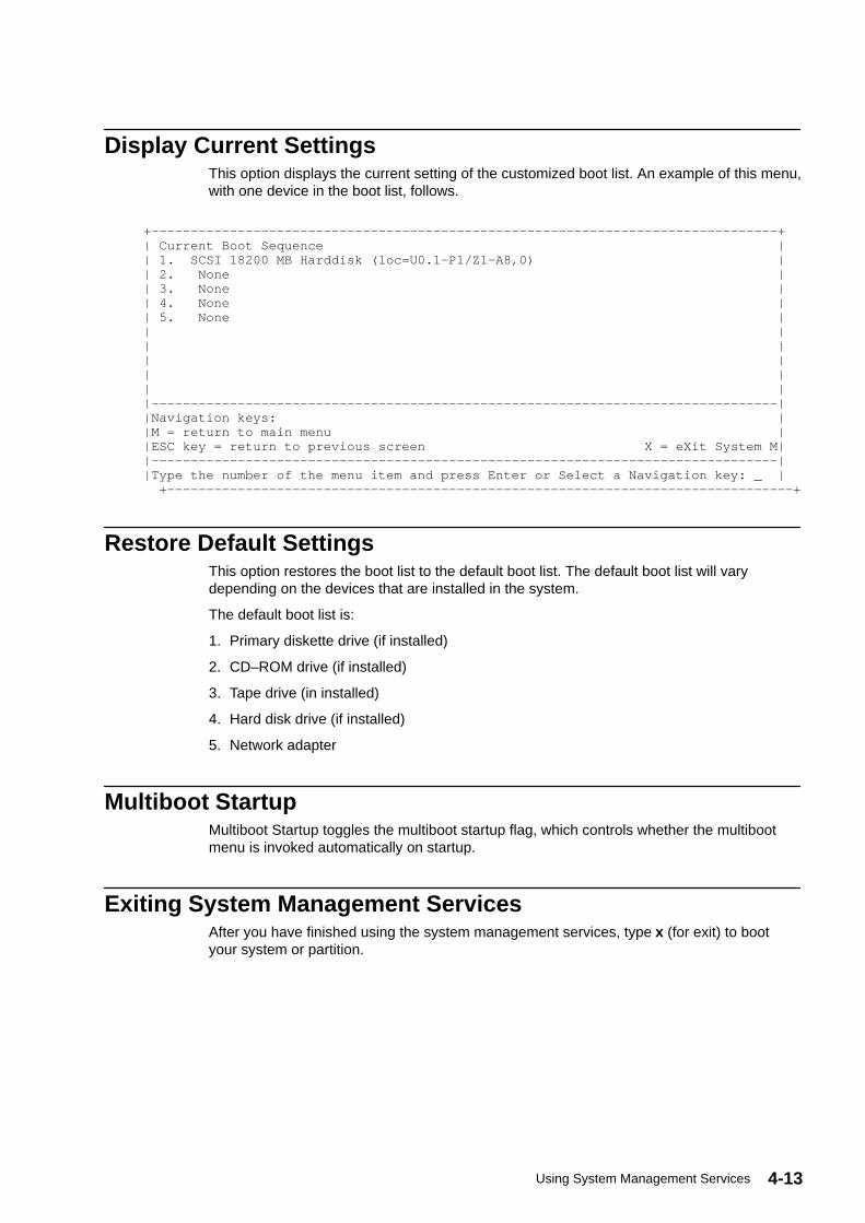
4-13Using System Management Services
Display Current SettingsThis option displays the current setting of the customized boot list. An example of this menu,with one device in the boot list, follows.
+––––––––––––––––––––––––––––––––––––––––––––––––––––––––––––––––––––––––––––––––+ | Current Boot Sequence | | 1. SCSI 18200 MB Harddisk (loc=U0.1–P1/Z1–A8,0) | | 2. None | | 3. None | | 4. None | | 5. None | | | | | | | | | | | |––––––––––––––––––––––––––––––––––––––––––––––––––––––––––––––––––––––––––––––––| |Navigation keys: | |M = return to main menu | |ESC key = return to previous screen X = eXit System M| |––––––––––––––––––––––––––––––––––––––––––––––––––––––––––––––––––––––––––––––––| |Type the number of the menu item and press Enter or Select a Navigation key: _ |
+––––––––––––––––––––––––––––––––––––––––––––––––––––––––––––––––––––––––––––––––+
Restore Default SettingsThis option restores the boot list to the default boot list. The default boot list will varydepending on the devices that are installed in the system.
The default boot list is:
1. Primary diskette drive (if installed)
2. CD–ROM drive (if installed)
3. Tape drive (in installed)
4. Hard disk drive (if installed)
5. Network adapter
Multiboot StartupMultiboot Startup toggles the multiboot startup flag, which controls whether the multibootmenu is invoked automatically on startup.
Exiting System Management ServicesAfter you have finished using the system management services, type x (for exit) to bootyour system or partition.

4-14 Escala PL820R User’s Guide

5-1Using the Online and Standalone Diagnostics
Chapter 5. Using the Online and StandaloneDiagnostics
The AIX diagnostics consist of online diagnostics and standalone diagnostics.
Attention: The AIX operating system must be installed in a partition in order to run onlinediagnostics on that partition. If the AIX operating system is not installed, use the standalonediagnostic procedures.
Online diagnostics, when they are installed, reside with AIX in the file system. They can bebooted:
• In single user mode (referred to as service mode)
• To run in maintenance mode (referred to as maintenance mode)
• To run concurrently with other applications (referred to as concurrent mode)
Standalone diagnostics must be booted before they can be run. If booted, the diagnosticshave no access to the AIX error log or the AIX configuration data.
Does the system have AIX diagnostics preinstalled?
Yes If there is an HMC attached to the system, go to Operating Considerationsfor Online and Standalone Diagnostics on page 5-1.
If an HMC is not attached to the system, go to Running the Online Diagnostics withNo HMC Attached on page 5-3.
No If there is an HMC attached to the system, go to Loading the StandaloneDiagnostics from CD–ROM Using an HMC on page 5-6.
If an HMC is not attached to the system, go to Running the Standalone Diagnosticswith CD–ROM with No HMC Attached on page 5-6.
If standalone diagnostics will be run from a NIM server, go to Running StandaloneDiagnostics from a Network Installation Management (NIM) Server on page 5-7. Ifan HMC is not attached to the system, follow the directions for a full system partition.
Operating Considerations for Online and StandaloneDiagnostics
Note: When possible, run online diagnostics in service mode. Online diagnosticsperform additional functions compared to standalone diagnostics. Runningonline diagnostics in service mode ensures that the error state of thesystem that has been captured in NVRAM is available for your use inanalyzing the problem. The AIX error log and certain SMIT functions areonly available when diagnostics are run from the disk drive.
Consider the following items before using the diagnostics:
• Standalone diagnostics can run on systems configured for either a full (or single) systempartition or a multiple partitioned system. When running in a partitioned system, thedevice from which you are booting standalone diagnostics must be made available to thepartition dedicated to running standalone diagnostics. This may require moving thedevice from the partition that currently contains the boot device (for example, theCD–ROM or network adapter connected to the NIM server that has a standalonediagnostic image) to the partition used to run standalone diagnostics. For partitionsrunning AIX levels earlier than AIX 5.2, if you move devices, reboot both source and

5-2 Escala PL820R User’s Guide
destination partitions. For more information, see Standalone Diagnostic Operation onpage 5-5.
• When diagnostics are installed, the device support for some devices might not getinstalled. If this is the case, that device does not display in the diagnostic test list whenrunning disk–based diagnostics.
• When running diagnostics in a partitioned system, diagnostics will work only with theresources that were assigned to that partition. You must run diagnostics in the partitioncontaining the resource that you want to test.
Identifying the Terminal Type to the DiagnosticsWhen you run diagnostics, you must identify which type of terminal you are using. If theterminal type is not known when the FUNCTION SELECTION menu is displayed, thediagnostics do not allow you to continue until a terminal is selected from the DEFINETERMINAL option menu. Choose the lft selection when running diagnostics from an HMC.
Undefined Terminal TypesIf you specify an undefined terminal type from the DEFINE TERMINAL option menu, themenu prompts the user to enter a valid terminal type. The menu redisplays until either avalid type is entered or you exit the DEFINE TERMINAL option. For a system attached to anHMC use VT320 emulation. If the AIX operating system is being used, from the commandline, type: export term=vt320
Resetting the TerminalIf you enter a terminal type that is valid (according to the DEFINE TERMINAL option menu)but is not the correct type for the HMC virtual terminal window being used, you may beunable to read the screen, use the function keys, or use the Enter key. Bypass thesedifficulties by pressing Ctrl–C to reset the terminal. The screen display that results from thisreset depends on the mode in which the system is being run:
• Online Normal or Maintenance Mode – The command prompt displays.
• Standalone Mode or Online Service Mode – The terminal type is reset to dumb, theDiagnostic Operating Instruction panel displays, and you are required to go through theDEFINE TERMINAL process again.
Online Diagnostics Modes of OperationNotes:
1. When running online diagnostics on a partition in a partitioned system, diagnostics canbe run only on resources that are allocated to that partition.
2. Online diagnostics can only be run in a partition with AIX installed.
The online diagnostics can be run in the following modes:
• Service Mode
• Concurrent Mode
• Maintenance Mode
Service ModeService mode provides the most complete checkout of the system resources. This modealso requires that no other programs be running on the partition or on a full system partition.Except for the SCSI adapter and the disk drives used for paging, resources on all partitionsor systems on a full system partition can be tested. However, note that the memory andprocessor are only tested during POST, and the results of the POST tests are reported bydiagnostics.

5-3Using the Online and Standalone Diagnostics
Error–log analysis is done in service mode when you select the Problem Determinationoption on the DIAGNOSTIC MODE SELECTION menu.
Consider the following when you run the online diagnostics from a server or a disk:
• The diagnostics cannot be loaded and run from a disk until the AIX operating system hasbeen installed and configured.
• The diagnostics cannot be loaded on a system (client) from a server if that system is notset up to boot from a server over a network. When the system is set up to boot from aserver, the diagnostics are run in the same manner as they are from disk.
• On a full system partition, if the diagnostics are loaded from disk or a server, you mustshut down the AIX operating system before turning off the system unit to preventpossible damage to disk data. Do this in either of the following ways:
– If the diagnostics were loaded in standalone mode, press the F3 key untilDIAGNOSTIC OPERATING INSTRUCTIONS displays. Then press the F3 key onceagain to shut down the AIX operating system.
– If the diagnostics were loaded in maintenance or concurrent mode, type theshutdown –F command.
• Under some conditions, the system might stop, with instructions displayed on attacheddisplays and terminals. Follow the instructions to select a console display.
Running Online Diagnostics in Service Mode with an HMC Attached to the SystemTo run the online diagnostics in service mode from the boot hard disk, do the following:
1. From the HMC, select Partition Manager .
2. Right–click on the mouse and select Open Terminal Window .
3. From the Service Processor Menu on the VTERM, select Option 2 System PowerControl .
4. Select option 6. Verify that the state changes to currently disabled . Disabling fastsystem boot automatically enables slow boot.
5. Select Option 98 to exit the system power control menu.
6. Use the HMC to power on the managed system in a full system partition by selecting themanaged system in the Contents area.
7. Right–click or select the desired system in the Contents area. Next, on the menu, chooseSelected .
8. Select Power On .
9. Select the Power on Diagnostic Stored Boot list option (refer to ”Full SystemManagement Tasks” in the Hardware Management Console Installation and OperationsGuide, order number 86 A1 83EF, for more information on full system partitions).
10.Make sure that there is no media in the devices in the media drive.
11.Enter any passwords, if requested.
Note: If you are unable to load the diagnostics to the point when theDIAGNOSTIC OPERATING INSTRUCTIONS display, go to Using theHMC to Load the Standalone Diagnostics from CD–ROM on page 7-2 .
Running the Online Diagnostics with No HMC AttachedOnline diagnostics can be loaded by booting from a hard file in the custom boot list bypressing the numeric 6 key on the keyboard.
To boot from the devices listed in the service mode boot list, perform the followingprocedure:

5-4 Escala PL820R User’s Guide
1. Verify with the system administrator and users that all programs may be stopped, thendo so.
2. Turn off the system.
Note: If AIX is running, type the shutdown command.
3. Wait until the Power–on LED stops flashing and remains off, then press the power buttonto turn the system on.
4. When the keyboard indicator appears during startup, press the numeric 6 key on thekeyboard.
5. Enter any requested passwords.
After any requested passwords have been entered, the system attempts to boot from thefirst device of each type found on the list. If no bootable image is found on the first device ofeach type on the list, the system does not search through the other devices of that type for abootable image; instead, it polls the first device of the next type.
If all types of devices in the boot list have been polled without finding a bootable image, thesystem restarts. This action gives the user the opportunity to start the System ManagementServices (by pressing the number 1 key on a directly attached keyboard or the number 1 onan ASCII terminal) before the system attempts to boot again.
Concurrent ModeRunning the online diagnostics in concurrent mode is started by entering diag at an AIXprompt. Use concurrent mode to run online diagnostics on some of the system resourceswhile the system is running normal activity.
Because the system is running in normal operation, the following resources cannot betested in concurrent mode:
• SCSI adapters connected to paging devices
• Disk drive used for paging
• Some display adapters and graphics related devices
• Memory (tested during POST)
• Processor (tested during POST)
The following levels of testing exist in concurrent mode:
• The share–test level tests a resource while the resource is being shared by programsrunning in the normal operation. This testing is mostly limited to normal commands thattest for the presence of a device or adapter.
• The sub–test level tests a portion of a resource while the remaining part of the resourceis being used in normal operation. For example, this test could test one port of amultiport device while the other ports are being used in normal operation.
• The full–test level requires the device not be assigned to or used by any otheroperation. This level of testing on a disk drive might require the use of the varyoffcommand. The diagnostics display menus to allow you to vary off the needed resource.
Error–log analysis is done in concurrent mode when you select the Problem Determinationoption on the DIAGNOSTIC MODE SELECTION menu.
To run the online diagnostics in concurrent mode, you must be logged in to the AIXoperating system and have proper authority to issue the commands (if help is needed, seethe system operator).
The diag command loads the diagnostic controller and displays the online diagnosticmenus.

5-5Using the Online and Standalone Diagnostics
Running the Online Diagnostics in Concurrent ModeTo run online diagnostics in concurrent mode, do the following:
1. Log in to the AIX operating system as root user, or use CE Login.
2. Enter the diag command.
3. When the DIAGNOSTIC OPERATING INSTRUCTIONS display, follow the instructions tocheck out the desired resources.
4. When testing is complete, use the F3 key to return to the DIAGNOSTIC OPERATINGINSTRUCTIONS. Press the F3 key again to return to the AIX operating system prompt.Be sure to vary on any resource that you had varied to off.
5. Press Ctrl–D to log off from root user or CE Login.
Maintenance ModeMaintenance mode runs the online diagnostics using the customer’s version of the AIXoperating system. This mode requires that all activity on the partition running the AIXoperating system be stopped so that the online diagnostics have most of the resourcesavailable to check. All of the system resources, except the SCSI adapters, memory,processor, and the disk drive used for paging, can be checked.
Error log analysis is done in maintenance mode when you select the ProblemDetermination option on the DIAGNOSTIC MODE SELECTION menu.
Use the shutdown –m command to stop all activity on the AIX operating system and putthe AIX operating system into maintenance mode. The diag command is then used toinvoke the diagnostic controller so you can run the diagnostics. After the diagnosticcontroller is loaded, follow the normal diagnostic instructions.
Running the Online Diagnostics in Maintenance ModeTo run the online diagnostics in maintenance mode, do the following:
1. Stop all programs running on the partition except the AIX operating system (if help isneeded, see the system operator).
2. Log in to the AIX operating system as root user, or use CE Login.
3. Type the shutdown –m command.
4. When a message indicates the system is in maintenance mode, enter the diagcommand.
Note: It might be necessary to set TERM type again.
5. When DIAGNOSTIC OPERATING INSTRUCTIONS screen displays, follow thedisplayed instructions to check out the desired resources.
6. When testing is complete, use the F3 key to return to DIAGNOSTIC OPERATINGINSTRUCTIONS. Press the F3 key again to return to the AIX operating system prompt.
7. Press Ctrl–D to log off from root user or CE Login.
Standalone Diagnostic OperationUse standalone diagnostics to test the system when the online diagnostics are not installedand as a method of testing the disk drives that cannot be tested by the online diagnostics.
Note: No error log analysis is done by the standalone diagnostics. The CD–ROMdrive and the SCSI controller that controls it cannot be tested by thestandalone diagnostics. Standalone diagnostics:
– Are resident on CD–ROM or a Network Installation Management (NIM) server

5-6 Escala PL820R User’s Guide
– Provide a method to test the system when the online diagnostics are not installedor cannot be loaded from the disk drive
– Allow testing of the disk drives and other resources that cannot be tested by theonline diagnostics
– Do not have access to the AIX configuration data
– Do not have access to the AIX error log
– Do not allow for running of error log analysis
Considerations for Running Standalone Diagnostics from CD–ROMConsider the following when you run standalone diagnostics:
• The diagnostic CD must remain in the CD–ROM drive for the entire time that diagnosticsare running.
• The diagnostic CD cannot be ejected from the CD–ROM drive after the diagnostics haveloaded. The CD can only be ejected after the system has been turned off and thenturned on (standalone mode) or after the diagnostics program has terminated (onlineconcurrent mode).
• The CD–ROM drive from which diagnostics were loaded cannot be tested.
• The SCSI adapter (or circuitry) controlling the CD–ROM drive from which diagnosticswere loaded cannot be tested.
Loading the Standalone Diagnostics from CD–ROM Using an HMCTo run standalone diagnostics in service mode from CD–ROM, do the following:
1. Stop all programs including the AIX operating system (get help if needed).
2. Remove all tapes, diskettes, and CD–ROMs.
3. Power off the 406/50 (refer to Full System Management Tasks in the HardwareManagement Console Installation and Operations Guide, order number 86 A1 83EF.
4. Right–click the mouse and select Open Terminal Window .
5. From the service processor menu on the VTERM, select option 2, System PowerControl Menu .
6. Select option 6. Verify that the state changes to currently disabled . Disabling fastsystem boot automatically enables slow boot.
7. Select option 98 to exit the system power control menu.
8. Use the HMC to power on the managed server in a full system partition. Select thePower on Diagnostic Default Boot List (refer to Full System Management Tasks in theHardware Management Console Installation and Operations Guide, order number 86 A183EF).
9. Insert the CD–ROM into the system’s CD–ROM drive (not into the HMC’s CD–ROMdrive).
Running the Standalone Diagnostics with CD–ROM with No HMC AttachedTo load standalone diagnostics from the default boot list, perform the following procedure:
1. Verify with the system administrator and users that all programs may be stopped, thendo so.
2. Turn off the system.
Note: If AIX is running, type the shutdown command. If Linux is running,type the shutdown now –h command.

5-7Using the Online and Standalone Diagnostics
3. Wait until the Power–on LED stops flashing and remains off, then press the power buttonto turn on the system.
4. Immediately insert the diagnostic CD–ROM into the CD–ROM drive.
5. When or after the word keyboard appears during startup, press the numeric 5 key onthe keyboard.
6. Enter any requested passwords.
Running Standalone Diagnostics from a Network InstallationManagement (NIM) Server
A client system connected to a network with a Network Installation Management (NIM)server can boot standalone diagnostics from the NIM server if the client–specific settings onboth the NIM server and client are correct.
Notes:
1. All operations to configure the NIM server require root user authority.
2. If you replace the network adapter in the client, the network adapter hardware addresssettings for the client must be updated on the NIM server.
3. The Cstate for each standalone diagnostics client on the NIM server should be kept inthe diagnostic boot has been enabled state.
4. On the client system, the NIM server network adapter should be put in the bootlist afterthe boot disk drive. This allows the system to boot in standalone diagnostics from theNIM server if there is a problem booting from the disk drive. Refer to the Multibootsection under ”SMS” in the client system’s service guide for information on setting thebootlist.
NIM Server ConfigurationRefer to the ”Advanced NIM Configuration Tasks” chapter of the AIX Installation Guide andReference, order number SC23–4389 for information on doing the following:
• Registering a client on the NIM server
• Enabling a client to run diagnostics from the NIM server
To verify that the client system is registered on the NIM server and the diagnostic boot isenabled, run the command lsnim –a Cstate –Z ClientName from the command line on theNIM server. Refer to the following table for system responses.
Note: The ClientName is the name of the system on which you want to runstandalone diagnostics.

5-8 Escala PL820R User’s Guide
System Response Client Status
#name:Cstate: ClientName:diagnostic boot has been enabled:
The client system is registered on the NIMserver and enabled to run diagnostics fromthe NIM server.
#name:Cstate: ClientName:ready for a NIMoperation:
or
#name:Cstate: ClientName:BOS installation hasbeen enabled:
The client is registered on the NIM serverbut not enabled to run diagnostics from theNIM server.
Note:If the client system is registered on theNIM server but Cstate has not been set,no data will be returned.
0042–053 lsnim: there is no NIMobject named ”ClientName”
The client is not registered on the NIMserver.
Booting Standalone Diagnostics from the NIM Server on a System withan HMC Attached
To run standalone diagnostics on a client from the NIM server, do the following:
1. Remove any removable media (tape or CD–ROM).
2. Stop all programs including the AIX operating system (get help if needed).
3. If you are running standalone diagnostics in a full system partition, verify with the systemadministrator and system users that the system unit can shut down. Stop all programs,including the AIX operating system. Refer to the AIX operating system documentation forshutdown command information.
Verify with the system administrator and system users using that partition that allapplications on that partition must be stopped, and that the partition will be rebooted.Stop all programs on that partition, including the operating system.
4. If you are in a full system partition, power on the system unit to run standalonediagnostics. In a partitioned system, reboot the partition to run standalone diagnostics.
5. When the keyboard indicator is displayed (the word keyboard on a HMC virtual terminalwindow or the keyboard icon on a graphical display), press the number 1 key on thekeyboard to display the SMS menu.
6. Enter any requested passwords.
7. Select Set Up Remote IPL (Initial Program Load).
8. Enter the client address, server address, gateway address (if applicable), and subnetmask.
9. If the NIM server is set up to allow pinging from the client system, use the ping utility inthe RIPL utility to verify that the client system can ping the NIM server. Under the pingutility, choose the network adapter that provides the attachment to the NIM server to dothe ping operation. If ping returns with an OK prompt, the client is prepared to boot fromthe NIM server. If ping returns with a FAILED prompt, the client cannot proceed with theNIM boot.
Note: If the ping fails, contact your service representative.
To do a one–time boot of the network adapter attached to the NIM server network, do thefollowing:
1. Exit to the SMS Main screen.
2. Select Select Boot Options .
3. Select Install or Boot a Device .
4. On the Select Device Type screen. select Network .

5-9Using the Online and Standalone Diagnostics
5. Set the network parameters for the adapter from which you want to boot.
6. Exit completely from SMS. The system starts loading packets while doing a bootp fromthe network.
Follow the instructions on the screen to select the system console.
• If Diagnostics Operating Instructions Version x.x.x displays,standalone diagnostics have loaded successfully.
• If the AIX login prompt displays, standalone diagnostics did not load. Check the followingitems:
– The network parameters on the client may be incorrect.
– Cstate on the NIM server may be incorrect.
– Network problems might be preventing you from connecting to the NIM server.
Verify the settings and the status of the network. If you continue to have problems, contactyour service representative.

5-10 Escala PL820R User’s Guide

6-1Introducing Tasks and Service Aids
Chapter 6. Introducing Tasks and Service Aids
The AIX Diagnostic Package contains programs that are called Tasks. Tasks can be thoughtof as performing a specific function on a resource; for example, running diagnostics orperforming a service aid on a resource.
Notes:
1. Many of these programs work on all system model architectures. Some programs areonly accessible from Online Diagnostics in Service or Concurrent mode, while othersmight be accessible only from Standalone Diagnostics.
2. If the system is running on a logically partitioned system, the following tasks can beexecuted only in a partition with service authority:
– Configure Reboot Policy
– Configure Remote Maintenance Policy
– Configure Ring Indicate Power On
– Configure Ring Indicate Power–On Policy
– Update System or Service Processor Flash
– Save or Restore Hardware Management Policies
– Configure Scan Dump Policy
To perform one of these tasks, use the Task Selection option from the FUNCTIONSELECTION menu.
After a task is selected, a resource menu may be presented showing all resourcessupported by the task.
A fast–path method is also available to perform a task by using the diag command and the–T flag. By using the fast path, the user can bypass most of the introductory menus toaccess a particular task. The user is presented with a list of resources available to supportthe specified task. The fast–path tasks are as follows:
• Certify – Certifies media
• Chkspares – Checks for the availability of spare sectors
• Download – Downloads microcode to an adapter or device
• Disp_mcode – Displays current level of microcode
• Format – Formats media
• Identify – Identifies the PCI RAID physical disks
• IdentifyRemove – Identifies and removes devices (Hot Plug)
To run these tasks directly from the command line, specify the resource and othertask–unique flags. Use the descriptions in this chapter to understand which flags areneeded for a given task.

6-2 Escala PL820R User’s Guide
TasksThe following tasks are described in this chapter:
• Add Resource to Resource List
• AIX Shell Prompt
• Analyze Adapter Internal Log
• Backup and Restore Media
• Certify Media
• Change Hardware Vital Product Data
• Configure Dials and LPF Keys
• Configure ISA Adapters
• Configure Reboot Policy
• Configure Remote Maintenance Policy
• Configure Ring Indicate Power–On Policy
• Configure Scan Dump Policy
• Configure Surveillance Policy
• Create Customized Configuration Diskette
• Delete Resource from Resource List
• Disk Maintenance
• Display Configuration and Resource List
• Display Firmware Device Node Information
• Display Hardware Error Report
• Display Hardware Vital Product Data
• Display Machine Check Error Log
• Display Microcode Level
• Display Multipath I/O (MPIO) Device Configuration
• Display or Change Bootlist
• Display or Change Diagnostic Run Time Options
• Display Previous Diagnostic Results
• Display Resource Attributes
• Display Service Hints
• Display Software Product Data
• Display System Environmental Sensors
• Display Test Patterns
• Display USB Devices
• Download Microcode
• Fibre Channel RAID Service Aids
• Flash SK–NET FDDI Firmware
• Format Media
6-3Introducing Tasks and Service Aids
• Gather System Information
• Generic Microcode Download
• Hot Plug Task
• Identify Indicators
• Identify and System Attention Indicators
• Local Area Network Analyzer
• Log Repair Action
• Periodic Diagnostics
• PCI RAID Physical Disk Identify
• Process Supplemental Media
• Run Diagnostics
• Run Error Log Analysis
• Run Exercisers
• Save or Restore Hardware Management Policies
• SCSI Bus Analyzer
• SCSI RAID Physical Disk Status and Vital Product Data
• SCSD Tape Drive Service Aid
• Spare Sector Availability
• System Fault Indicator
• System Identify Indicator
• Update Disk–Based Diagnostics
• Update System or Service Processor Flash
• 7318 Serial Communication Network Server
Add Resource to Resource ListUse this task to add resources back to the resource list.
Note: Only resources that were previously detected by the diagnostics anddeleted from the Diagnostic Test List are listed. If no resources are availableto be added, then none are listed.
AIX Shell PromptNote: Use this service aid in Online Service Mode only.
This service aid allows access to the AIX command line. To use this service aid, the usermust know the root password (when a root password has been established).
Note: Do not use this task to install code or to change the configuration of thesystem. This task is intended to view files, configuration records, and data.Using this service aid to change the system configuration or install code canproduce unexplained system problems after exiting the diagnostics.

6-4 Escala PL820R User’s Guide
Analyze Adapter Internal LogThe PCI RAID adapter has an internal log that logs information about the adapter and thedisk drives attached to the adapter. Whenever data is logged in the internal log, the devicedriver copies the entries to the AIX system error log and clears the internal log.
The Analyze Adapter Internal Log service aid analyzes these entries in the AIX system errorlog. The service aid displays the errors and the associated service actions. Entries that donot require any service actions are ignored.
When running this service aid, a menu is presented to enter the start time, the end time, andthe file name. The start time and end time have the following format: [ mmddHHMMyy ].(where mm is the month (1–12), dd is the date (1–31) HH is the hour (00–23) MM is theminute (00–59), and yy is the last two digits of the year (00–99). The file name is thelocation where the user wants to store the output data.
To invoke the service aid task from the command line, type:
diag –c –d devicename –T ” adapela [–s start date –e end date ]
Flag Description
–c Specifies not console mode.
–d devicename Specifies the device whose internal log you want to analyze (for example,SCRAID0 )
–s start date Specifies all errors after this date are analyzed.
–e end date Specifies all errors before this date are analyzed.
–T Specifies the Analyze Adapter Internal Log task
Note: To specify a file name from the command line, use the redirection operatorat the end of the command to specify where the output of the command isto be sent, for example > filename (where filename is the name andlocation where the user wants to store the output data (for example,/tmp/adaptlog ).
Backup and Restore MediaThis service aid allows verification of backup media and devices. It presents a menu of tapeand diskette devices available for testing and prompts for selecting the desired device. Itthen presents a menu of available backup formats and prompts for selecting the desiredformat. The supported formats are tar, backup , and cpio . After the device and format areselected, the service aid backs up a known file to the selected device, restores that file to/tmp , and compares the original file to the restored file. The restored file remains in /tmp toallow for visual comparison. All errors are reported.
Certify MediaThis task allows the selection of diskette, DVD–RAM media, or hard files to be certified.Normally, this is done under the following conditions:
• To determine the condition of the drive and media
• To verify that the media is error free after a Format Service Aid has been run on themedia
Normally, run certify if after running diagnostics on a drive and its media, no problem isfound, but you suspect that a problem still exists.

6-5Introducing Tasks and Service Aids
Hard files can be connected either to a SCSI adapter (non–RAID) or a PCI SCSI RAIDadapter. The usage and criteria for a hard file connected to a non–RAID SCSI adapter aredifferent from those for a hard file connected to a PCI SCSI RAID adapter.
Certify Media can be used in the following ways:
• Certify Diskette
This selection enables you to verify the data written on a diskette. When you select thisservice aid, a menu asks you to select the type of diskette being verified. The programthen reads all of the ID and data fields on the diskette one time and displays the totalnumber of bad sectors found.
• Certify DVD–RAM media
This selection reads all of the ID and data fields. It checks for bad data and counts allerrors encountered. If an unrecovered error occurs, or recovered errors exceed thethreshold value, the data on the media should be transferred to other media and theoriginal media should be discarded.
The Certify service aid will display the following information:
– Capacity in bytes
– Number of Data Errors Not Recovered
– Number of Equipment Check Errors
– Number of Recovered Errors
If the drive is reset during a certify operation, the operation is restarted.
If the drive is reset again, the certify operation is terminated, and the user is asked to rundiagnostics on the drive.
This task can be run directly from the AIX command line. See the following commandsyntax: diag –c –d –T certify
Flag Description
–c No console mode
–d Specifies a device
–T Specifies the certify task
• Certify Hardfile Attached to a Non–RAID SCSI Adapter
This selection reads all of the ID and data fields. It checks for bad data and counts allerrors encountered. If there are unrecovered data errors that do not exceed thethreshold value, the hard file must be formatted and certified. If the unrecovered dataerrors, recovered data errors, recovered and unrecovered equipment errors exceed thethreshold values, the disk must be replaced.
It also makes 2000 random seeks after the read certify of the surface completes. If a disktimes out before finishing the random seeks, then the disk needs to be replaced. Therandom seeks also count all errors encountered.
The Certify service aid will display the following information:
– Drive capacity in megabytes.
– Number of Data Errors Recovered.
– Number of Data Errors Not Recovered.
– Number of Equipment Checks Recovered.
– Number of Equipment Checks Not Recovered.
This task can be run directly from the AIX command line. See the following commandsyntax: diag –c –d deviceName –T ”certify”

6-6 Escala PL820R User’s Guide
Flag Description
–c No console mode
–d Specifies a device
–T Specifies the certify task
• Format and/or Erase Hardfile Attached to a Non–RAID SCSI Adapter
Attention: The following commands WILL change the content of the hardfile. Be sure tobackup data prior to running the command, and take care in choosing the hardfile uponwhich you run this task.
– Hardfile Format
Writes all of the disk. The pattern written on the disk is device–dependant; forexample, some drives may write all 0s, while some may write the hexadecimalnumber 5F. No bad–block reassignment occurs.
– Hardfile Format and Certify
Performs the same function as Hardfile Format. After the format is completed, Certifyis run. Certify then reassigns all bad blocks encountered.
– Hardfile Erase Disk
This option can be used to overwrite (remove) all data currently stored inuser–accessible blocks of the disk. The Erase Disk option writes one or morepatterns to the disk. An additional option allows data in a selectable block to be readand displayed on the system console.
To use the Erase Disk option, specify the number (0–3) of patterns to be written. Thepatterns are written serially; that is, the first pattern is written to all blocks. Then thenext pattern is written to all blocks, overlaying the previous pattern. A random patternis written by selecting Write Random Pattern .
Note: The Erase Disk service aid has not been certified as meeting theDepartment of Defense or any other organization’s securityguidelines.
To overwrite the data on the drive, use the following steps:
1. Select Erase Disk .
2. Do a format without certify.
3. Select Erase Disk to run it a second time.
For a newly installed drive, you can ensure that all blocks on the drive are overwrittenwith your pattern if you use the following procedure:
1. Format the drive.
2. Check the defect MAP by running the Erase Disk selection.
Note: If you use Format and Certify option, there may be some blockswhich get placed into the grown defect MAP.
3. If there are bad blocks in the defect MAP, record the information presented andensure that this information is kept with the drive. This data is used later when thedrive is to be overwritten.
4. Use you drive as you would normally.
5. When the drive is no longer needed and is to be erased, run the same version ofthe Erase Disk selection which was used in step 2.
Note: Using the same version of the service aid is only critical if any badblocks were found in step 3.

6-7Introducing Tasks and Service Aids
6. Compare the bad blocks which were recorded for the drive in step 3 with those thatnow appear in the grown defect MAP.
Note: If there are differences between the saved data and the newlyobtained data, then all sectors on this drive cannot be overwritten.The new bad blocks are not overwritten.
7. If the bad block list is the same, continue running the service aid to overwrite thedisk with the chosen pattern(s).
This task can be run directly from the AIX command line. See the command syntax:diag –c –d deviceName –T ”format [–s* fmtcert | erase –a {read| write}] [–F]*
Flag Description
fmtcert Formats and certifies the disk.
erase Overwrites the data on the disk.
* Available in no–console mode only.
–F Force the disk erasure even if all blocks cannot be erased due toerrors accessing the grown defect map.
Note: The Erase Disk option in command line mode uses default values.To selectively read or write, use the diag command in console mode.
• Certify Hardfile attached to a PCI SCSI RAID Adapter
This selection is used to certify physical disks attached to a PCI SCSI RAID adapter.Certify reads the entire disk and checks for recovered errors, unrecovered errors, andreassigned errors. If these errors exceed the threshold values, the user is prompted toreplace the physical disk.
This task can be run directly from the AIX command line. See the following commandsyntax: diag –c –d RAIDadapterName –T ”certify {–l chID | –A}”
Flag Description
–c No console mode
–d Specifies the RAID adapter to which the disk is attached
–T Specifies the certify task and its parameters
–I Specifies physical Disk channel/ID (for example: –l 27)
–A All disks
Change Hardware Vital Product DataUse this service aid to display the Display/Alter VPD Selection Menu. The menu lists allresources installed on the system. When a resource is selected, a menu displays that listsall the VPD for that resource.
Note: The user cannot alter the VPD for a specific resource unless the VPD isnot machine–readable.
Configure Dials and LPF KeysNote: The Dials and LPF Keys service aid is not supported in standalone mode
(CD–ROM and NIM) on systems with 32 MB or less memory. If you haveproblems in standalone mode, use the hardfile–based diagnostics.
This service aid provides a tool for configuring and removing dials and LPF keys to theasynchronous serial ports.

6-8 Escala PL820R User’s Guide
This selection invokes the SMIT utility to allow Dials and LPF keys configuration. A TTYmust be in the available state on the async port before the Dials and LPF keys can beconfigured on the port. The task allows an async adapter to be configured, then a TTY portdefined on the adapter. Dials and LPF keys can then be defined on the port.
Before configuring Dials or LPF keys on a serial port, you must remove all defined TTYs. Todetermine if there are any defined TTYs, select List All Defined TTYs . Once all definedTTYs have been removed, then add a new TTY and configure the Dials or LPF keys.
Configure ISA AdapterThis task uses SMIT to identify and configure ISA adapters on systems that have an ISAbus and adapters.
Diagnostic support for ISA adapters not shown in the list may be supported from asupplemental diskette. You can use the Process Supplemental Media task to add ISAadapter support from a supplemental diskette.
Whenever an ISA adapter is installed, this service aid must be run and the adapterconfigured before the adapter can be tested. You must also run this service aid to removean ISA adapter from the system whenever an ISA adapter is physically removed from thesystem.
If diagnostics are run on an ISA adapter that has been removed from the system, thediagnostics fail because the system cannot detect the ISA adapter.
Configure Reboot PolicyThis service aid controls how the system tries to recover from a system crash.
Use this service aid to display and change the following settings for the Reboot Policy.
Note: Because of system capability, some of the following settings might not bedisplayed by this service aid.
• Maximum Number of Reboot Attempts
Enter a number that is 0 or greater.
Note: A value of 0 indicates ’do not attempt to reboot’ to a crashed system.
This number is the maximum number of consecutive attempts to reboot the system. Theterm reboot, in the context of this service aid, describes bringing system hardware backup from scratch; for example, from a system reset or power–on.
When the reboot process completes successfully, the reboot–attempts count is reset to0, and a restart begins. The term restart, in the context of this service aid, is used todescribe the operating system activation process. Restart always follows a successfulreboot.
When a restart fails, and a restart policy is enabled, the system attempts to reboot for themaximum number of attempts.
• Use the O/S Defined Restart Policy (1=Yes, 0=No)
When ’Use the O/S Defined Restart Policy’ is set to Yes, the system attempts to rebootfrom a crash if the operating system has an enabled Defined Restart or Reboot Policy.
When ’Use the O/S Defined Restart Policy’ is set to No, or the operating system restartpolicy is undefined, then the restart policy is determined by the ’Supplemental RestartPolicy’.
• Enable Supplemental Restart Policy (1=Yes, 0=No)

6-9Introducing Tasks and Service Aids
The ’Supplemental Restart Policy’, if enabled, is used when the O/S Defined RestartPolicy is undefined, or is set to False.
When surveillance detects operating system inactivity during restart, an enabled’Supplemental Restart Policy’ causes a system reset and the reboot process begins.
• Call–Out Before Restart (on/off)
When enabled, Call–Out Before Restart allows the system to call out (on a serial portthat is enabled for call–out) when an operating system restart is initiated. Such calls canbe valuable if the number of these events becomes excessive, thus signalling biggerproblems.
• Enable Unattended Start Mode (1=Yes, 0=No)
When enabled, ’Unattended Start Mode’ allows the system to recover from the loss of acpower.
If the system was powered–on when the ac loss occurred, the system reboots whenpower is restored. If the system was powered–off when the ac loss occurred, the systemremains off when power is restored.
You can access this service aid directly from the AIX command line, by typing:/usr/lpp/diagnostics/bin/uspchrp –b
Configure Remote Maintenance PolicyThe Remote Maintenance Policy includes modem configurations and phone numbers to usefor remote maintenance support.
Use this service aid to display and change the following settings for the RemoteMaintenance Policy.
Note: Because of system capability, some of the following settings might not bedisplayed by this service aid.
• Configuration File for Modem on serial port 1 (S1)
Configuration File for Modem on serial port 2 (S2).
Enter the name of a modem configuration file to load on either S1 or S2. The modemconfiguration files are located in the directory /usr/share/modems . If a modem file isalready loaded, it is indicated by Modem file currently loaded .
• Modem file currently loaded on S1
Modem file currently loaded on S2
This is the name of the file that is currently loaded on serial port 1 or serial port 2.
Note: These settings are only shown when a modem file is loaded for a serialport.
• Call In Authorized on S1 (on/off)
Call In Authorized on S2 (on/off)
Call In allows the Service Processor to receive a call from a remote terminal.
• Call Out Authorized on S1 (on/off)
Call Out Authorized on S2 (on/off)
Call Out allows the Service Processor to place calls for maintenance.
• S1 Line Speed
S2 Line Speed
A list of line speeds is available by using List on the screen.

6-10 Escala PL820R User’s Guide
• Service Center Phone Number
This is the number of the service center computer. The service center usually includes acomputer that takes calls from systems with call–out capability. This computer is referredto as ”the catcher.” The catcher expects messages in a specific format to which theService Processor conforms. For more information about the format and catchercomputers, refer to the README file in the AIX /usr/samples/syscatch directory.Contact the service provider for the correct telephone number to enter here.
• Customer Administration Center Phone Number
This is the number of the System Administration Center computer (catcher) that receivesproblem calls from systems. Contact the system administrator for the correct telephonenumber to enter here.
• Digital Pager Phone Number In Event of Emergency
This is the number for a pager carried by someone who responds to problem calls fromyour system.
• Customer Voice Phone Number
This is the number for a telephone near the system, or answered by someoneresponsible for the system. This is the telephone number left on the pager for callback.
• Customer System Phone Number
This is the number to which your system’s modem is connected. The service oradministration center representatives need this number to make direct contact with yoursystem for problem investigation. This is also referred to as the Call In phonenumber .
• Customer Account Number
This number is available for service providers to use for record–keeping and billing.
• Call Out Policy Numbers to call if failure
This is set to either First or All. If the call–out policy is set to First, call out stops at thefirst successful call to one of the following numbers in the order listed:
1. Service Center
2. Customer Administration Center
3. Pager
If Call Out Policy is set to All, call–out attempts to call all of the following numbers in theorder listed:
1. Service Center
2. Customer Administration Center
3. Pager
• Remote Timeout, in seconds Remote Latency, in seconds
These settings are functions of the service provider’s catcher computer.
• Number of Retries While Busy
This is the number of times the system should retry calls that resulted in busy signals.
• System Name (System Administrator Aid)
This is the name given to the system and is used when reporting problem messages.
Note: Knowing the system name aids the support team in quickly identifyingthe location, configuration, history, and so on of your system.
You can access this service aid directly from the AIX command line, by typing:/usr/lpp/diagnostics/bin/uspchrp –m

6-11Introducing Tasks and Service Aids
Configure Ring Indicate Power–On PolicyThis service aid allows the user to power–on a system by telephone from a remote location.If the system is powered off, and Ring Indicate Power On is enabled, the system powers onat a predetermined number of rings. If the system is already on, no action is taken. In eithercase, the telephone call is not answered, and the caller receives no feedback that thesystem has powered on.
Use this service aid to display and change the following settings for the Ring IndicatePower–On Policy:
Because of system capability, some of the following settings might not be displayed by thisservice aid.
• Power On Via Ring Indicate (on/off)
• Number of Rings Before Power On
You can access this service aid directly from the AIX command line, by typing:/usr/lpp/diagnostics/bin/uspchrp –r
Configure Scan Dump PolicyConfigure Scan Dump Policy allows the user to set or view the scan dump policy (scandump control and size) in NVRAM. Scan Dump data is a set of chip data that the serviceprocessor gathers after a system malfunction. It consists of chip scan rings, chip tracearrays, and Scan COM (SCOM) registers. This data is stored in the scan–log partition of thesystem’s Nonvolatile Random Access Memory (NVRAM).
Use this service aid to display and change the following settings for the Scan Dump Policyat run time:
• Scan Dump Control (how often the dump is taken)
• Scan Dump Size (size and content of the dump)
The Scan Dump Control (SDC) settings are as follows:
• As Needed: This setting allows the platform firmware to determine whether a scan dumpis performed. This is the default setting for the dump policy.
• Always: This setting overrides the firmware recommendations and always performs adump after a system failure.
The Scan Dump Size (SDS) settings are as follows:
• As Requested – Dump content is determined by the platform firmware.
• Minimum – Dump content collected provides the minimum debug information, enablingthe platform to reboot as quickly as possible.
• Optimum – Dump content collected provides a moderate amount of debug information.
• Complete – Dump data provides the most complete error coverage at the expense ofreboot speed.
You can access this service aid directly from the AIX command line by typing:
/usr/lpp/diagnostics/bin/uspchrp –d
6-12 Escala PL820R User’s Guide
Configure Surveillance PolicyNote: This service aid is supported only for systems running in full machine
partition.
This service aid monitors the system for hang conditions; that is, hardware or softwarefailures that cause operating system inactivity. When enabled, and surveillance detectsoperating system inactivity, a call is placed to report the failure.
Use this service aid to display and change the following settings for the Surveillance Policy:
Note: Because of system capability, some of the following settings might not bedisplayed by this service aid:
• Surveillance (on/off)
• Surveillance Time Interval – This is the maximum time between heartbeats from theoperating system.
• Surveillance Time Delay – This is the time to delay between when the operating systemis in control and when to begin operating system surveillance.
• Changes are to Take Effect Immediately – Set this to Yes if the changes made to thesettings in this menu are to take place immediately. Otherwise, the changes take effectbeginning with the next system boot.
You can access this service aid directly from the AIX command line, by typing:/usr/lpp/diagnostics/bin/uspchrp –s
Create Customized Configuration DisketteThis selection invokes the Diagnostic Package Utility Service Aid, which allows the user tocreate a standalone diagnostic package configuration diskette.
The Standalone Diagnostic Package Configuration Diskette allows the following to bechanged from the console:
• Default refresh rate for a low function terminal (LFT)
The refresh rate used by the standalone diagnostic package is 60 Hz. If the display’srefresh rate is 77 Hz, set the refresh rate to 77.
• Different async terminal console
You can create a console configuration file that allows a terminal attached to any RS232or RS422 adapter to be selected as a console device. The default device is an RS232TTY device attached to the first standard serial port (S1).
Delete Resource from Resource ListUse this task to delete resources from the resource list.
Note: Only resources that were previously detected by the diagnostics and havenot been deleted from the Diagnostic Test List are listed. If no resources areavailable to be deleted, then none are listed.

6-13Introducing Tasks and Service Aids
Disk MaintenanceThis service aid provides the following options for the fixed–disk maintenance:
• Disk to Disk Copy
• Display/Alter Sector
Disk to Disk CopyNotes:
1. This service aid cannot be used to update to a different size drive. The service aid onlysupports copying from a SCSI drive to another SCSI drive of similar size.
2. Use the migratepv command when copying the contents to other disk drive types. Thiscommand also works when copying SCSI disk drives or when copying to a different sizeSCSI disk drive. Refer to System Management Guide: Operating System and Devicesfor a procedure on migrating the contents of a physical volume.
This publication is located on the AIX V4.3 Documentation CD. The documentationinformation is made accessible by loading the documentation CD onto the hard disk orby mounting the CD in the CD–ROM drive.
This selection allows you to recover data from an old drive when replacing it with a newdrive. The service aid recovers all logical volume manager (LVM) software reassignedblocks. To prevent corrupted data from being copied to the new drive, the service aid stopsif an unrecoverable read error is detected. To help prevent possible problems with the newdrive, the service aid stops if the number of bad blocks being reassigned reaches athreshold.
To use this service aid, both the old and new disks must be installed in or attached to thesystem with unique SCSI addresses. This requires that the new disk drive SCSI addressmust be set to an address that is not currently in use and the drive be installed in an emptylocation. If there are no empty locations, then one of the other drives must be removed.When the copy is complete, only one drive can remain installed. Either remove the targetdrive to return to the original configuration, or perform the following procedure to completethe replacement of the old drive with the new drive:
1. Remove both drives.
2. Set the SCSI address of the new drive to the SCSI address of the old drive.
3. Install the new drive in the old drive’s location.
4. Install any other drives (that were removed) into their original location.
To prevent problems that can occur when running this service aid from disk, it is suggestedthat this service aid be run, when possible, from the diagnostics that are loaded fromremovable media.
Display/Alter SectorNote: Use caution when you use this service aid because inappropriate
modification to some disk sectors can result in the total loss of all data onthe disk.
This selection allows the user to display and alter information on a disk sector. Sectors areaddressed by their decimal sector number. Data is displayed both in hex and in ASCII. Toprevent corrupted data from being incorrectly corrected, the service aid does not displayinformation that cannot be read correctly.

6-14 Escala PL820R User’s Guide
Display Configuration and Resource ListIf a device is not included in the Test List or if you think a Diagnostic Package for a device isnot loaded, check by using the Display Configuration and Resource List task. If the deviceyou want to test has a plus (+) sign or a minus (–) sign preceding its name, the DiagnosticPackage is loaded. If the device has an asterisk (*) preceding its name, the DiagnosticPackage for the device is not loaded or is not available.
This service aid displays the item header only for all installed resources. Use this service aidwhen there is no need to see the vital product data (VPD). (No VPD is displayed.)
Display Firmware Device Node InformationThis task displays the firmware device node information. This service aid is intended togather more information about individual or particular devices on the system. The format ofthe output data may differ depending on which level of the AIX operating system is installed.
Display Hardware Error ReportThis service aid uses the errpt command to view the hardware error log.
The Display Error Summary and Display Error Detail selection provide the same type ofreport as the errpt command. The Display Error Analysis Summary and Display ErrorAnalysis Detail selection provide additional analysis.
Display Hardware Vital Product DataThis service aid displays all installed resources, along with any VPD for those resources.Use this service aid when you want to look at the VPD for a specific resource.
Display Machine Check Error LogNote: The Machine Check Error Log Service Aid is available only on Standalone
Diagnostics.
When a machine check occurs, information is collected and logged in an NVRAM error logbefore the system unit shuts down. This information is logged in the AIX error log andcleared from NVRAM when the system is rebooted from the hard disk, LAN, or standalonemedia. When booting from Standalone Diagnostics, this service aid converts the loggedinformation into a readable format that can be used to isolate the problem. When bootingfrom the hard disk or LAN, the information can be viewed from the AIX error log using theHardware Error Report Service Aid. In either case, the information is analyzed when thesysplanar0 diagnostics are running in Problem Determination Mode.
Display Microcode LevelThis task is used to display the microcode or firmware levels of currently installed resources.When the sys0 resource is selected, the task displays the levels of both the systemfirmware and service processor firmware. sys0 may not be available in all cases.
You can display the current level of the microcode on an adapter, the system, or a device byusing the AIX diag command. See the following command syntax: diag –c –d device –T”disp_mcode”
Flag Description

6-15Introducing Tasks and Service Aids
–c No console mode.
–d Used to specify a device.
–T Use the disp_mcode option to display microcode.
The AIX lsmcode command serves as a command line interface to the Display MicrocodeLevel task. For information on the lsmcode command, refer to the AIX CommandsReference manual.
Display MultiPath I/O (MPIO) Device ConfigurationThis service aid displays the status of MPIO devices and their connections to their parentdevices.
This service aid is capable of sending SCSI commands on each available path regardless ofthe default MPIO path algorithm. Therefore, it is useful for testing the unused path forintegrity.
Run this service aid if it is suspected that there is a problem with the path between MPIOdevices and their parent devices.
This service aid is capable of:
• Listing MPIO devices
• Listing the parents of MPIO devices
• Displaying the status and location of specified MPIO devices
• Displaying the hierarchy of MPIO adapters and devices.
If there are no devices with multiple paths, this service aid will not be shown on the ”TaskSelection” menu.
Access this service aid directly from the AIX command line, by typing:
/usr/lpp/diagnostics/bin/umpio
Display or Change BootlistThis service aid allows the bootlist to be displayed, altered, or erased.
The system attempts to perform an IPL from the first device in the list. If the device is not avalid IPL device or if the IPL fails, the system proceeds in turn to the other devices in the listto attempt an IPL.
Display or Change Diagnostic Run–Time OptionsThe Display or Change Diagnostic Run–Time Options task allows the diagnostic run–timeoptions to be set.
Note: The run–time options are used only when selecting the Run Diagnostictask.
The run–time options are:
• Display Diagnostic Mode Selection Menus
This option allows the user to turn on or off displaying the DIAGNOSTIC MODESELECTION MENU (the default is on).
• Run Tests Multiple Times

6-16 Escala PL820R User’s Guide
This option allows the user to turn on or off, or specify a loop count, for diagnostic loopmode (the default is off).
Note: This option is only displayed when you run the Online Diagnostics inService Mode.
• Include Advanced Diagnostics
This option allows the user to turn on or off including the Advanced Diagnostics (thedefault is off).
• Include Error Log Analysis (not available in diagnostics 5.2.0 or later)
This option allows the user to turn on or off including the Error Log Analysis (ELA) (thedefault is off).
• Number of Days Used to Search Error Log
This option allows the user to select the number of days for which to search the AIX errorlog for errors when running the Error Log Analysis. The default is seven days, but it canbe changed from one to sixty days.
• Display Progress Indicators
This option allows the user to turn on or off the progress indicators when running theDiagnostic Applications. The progress indicators, in a box at the bottom of the screen,indicate that the test is being run (the default is on).
• Diagnostic Event Logging
This option allows the user to turn on or off logging information to the Diagnostic EventLog (the default is on).
• Diagnostic Event Log File Size
This option allows the user to select the maximum size of the Diagnostic Event Log. Thedefault size for the Diagnostic Event Log is 100 KB. The size can be increased in 100 KBincrements to a maximum of 1 MB.
Use the diaggetrto command to display one or more diagnostic run–time options. Use thefollowing AIX command line syntax:
/usr/lpp/diagnostics/bin/diaggetrto [–a] [–d] [–l] [–m] [–n] [–p] [–s]
Use the diagsetrto command to change one or more diagnostic run–time options. Use thefollowing AIX command line syntax:
/usr/lpp/diagnostics/bin/diagsetrto [–a on|off] [–d on|off] [–l size ] [–m on|off] [–n days ] [–p on|off]
Flag descriptions for the diaggetrto and diagsetrto commands are as follows:
Flag Description
–a Displays or changes the value of the Include Advanced Diagnostics option.
–d Displays or changes the value of the Diagnostic Event Logging option.
–l Displays or changes the value of the Diagnostic Event Log File Size.Allowable size are between 100K and 1000K in increments of 100K. Thesize may never be decreased.
–m Displays or changes the value of the Display Diagnostic Mode SelectionMenu option.
–n Displays or changes the value of the Number of Days Used To Search theError Log option. Allowable values are between 1 and 60 days. 7 days isthe default.

6-17Introducing Tasks and Service Aids
–p Displays or changes the value of the Display Progress Indicators option.
–s Displays all of the diagnostic run–time options.
Display Previous Diagnostic ResultsNote: This service aid is not available when you load the diagnostics from a
source other than a hard disk drive or a network.
This service aid allows a service representative to display results from a previous diagnosticsession. When the Display Previous Diagnostic Results option is selected, the user canview up to 25 no trouble found (NTF) and service request number (SRN) results.
This service aid displays Diagnostic Event Log information. You can display the DiagnosticEvent Log in a short version or a long version. The Diagnostic Event Log containsinformation about events logged by a diagnostic session.
This service aid displays the information in reverse chronological order.
This information is not from the AIX operating system error log. This information is stored inthe /var/adm/ras directory.
You can run the command from the AIX command line by typing:/usr/lpp/diagnostics/bin/diagrpt [[–o] | [–s mmddyy] | [–a] | [–r]]
Flag Description
–o Displays the last diagnostic results file stored in the/etc/lpp/diagnostics/data directory
–s mmddyy Displays all diagnostic result files logged since the date specified
–a Displays the long version of the Diagnostic Event Log
–r Displays the short version of the Diagnostic Event Log
Display Resource AttributesThis task displays the Customized Device Attributes associated with a selected resource.This task is similar to running the lsattr –E –l resource command.
Display Service HintsThis service aid reads and displays the information in the CEREADME file from thediagnostics media. This file contains information that is not contained in the publications forthis version of the diagnostics. The file also contains information about using this particularversion of diagnostics.
Display Software Product DataThis task uses SMIT to display information about the installed software and provides thefollowing functions:
• List Installed Software
• List Applied but Not Committed Software Updates
• Show Software Installation History
• Show Fix (APAR) Installation Status
• List Fileset Requisites
• List Fileset Dependents

6-18 Escala PL820R User’s Guide
• List Files Included in a Fileset
• List File Owner by Fileset
Display System Environmental SensorsThis service aid displays the environmental sensor information for the system. Theinformation displayed is the sensor name, physical location code, literal value of the sensorstatus, and the literal value of the sensor reading.
The sensor status can be any one of the following:
• Normal – The sensor reading is within the normal operating range.
• Critical High – The sensor reading indicates a serious problem with the device. Rundiagnostics on sysplanar0 to determine what repair action is needed.
• Critical Low – The sensor reading indicates a serious problem with the device. Rundiagnostics on sysplanar0 to determine what repair action is needed.
• Warning High – The sensor reading indicates a problem with the device. This couldbecome a critical problem if action is not taken. Run diagnostics on sysplanar0 todetermine what repair action is needed.
• Warning Low – The sensor reading indicates a problem with the device. This couldbecome a critical problem if action is not taken. Run diagnostics on sysplanar0 todetermine what repair action is needed.
• Hardware Error – The sensor could not be read because of a hardware error. Rundiagnostics on sysplanar0 in problem–determination mode to determine what repairaction is needed.
• Hardware Busy – The system has repeatedly returned a busy indication, and a readingis not available. Try the service aid again. If the problem continues, run diagnostics onsysplanar0 in problem–determination mode to determine what repair action is needed.
This service aid can also be run as a command. You can use the command to list thesensors and their values in a text format, list the sensors and their values in numericalformat, or a specific sensor can be queried to return either the sensor status or sensorvalue.
Run the command by entering one of the following:/usr/lpp/diagnostics/bin/uesensor –l | –a/usr/lpp/diagnostics/bin/uesensor –t token –i index [–v]
Flag Description
–l List the sensors and their values in a text format.
–a List the sensors and their values in a numerical format. For each sensor,the numerical values are displayed as: token index status measured valuelocation code
–t token Specifies the sensor token to query.
–i index Specifies the sensor index to query.
–v Indicates to return the sensor measured value. The sensor status isreturned by default.

6-19Introducing Tasks and Service Aids
ExamplesThe following are examples from this command:
1. Display a list of the environmental sensors: /usr/lpp/diagnostics/bin/uesensor–lSensor = Fan SpeedStatus = NormalValue = 2436 RPMLocation Code = F1Sensor = Power SupplyStatus = NormalValue = Present and operationalLocation Code = V1Sensor = Power SupplyStatus = Critical lowValue = Present and not operationalLocation Code = V2
2. Display a list of the environmental sensors in a numerical list:/usr/lpp/diagnostics/bin/uesensor –a3 0 11 87 P19001 0 11 2345 F19004 0 11 2 V19004 1 9 2 V2
3. Return the status of sensor 9004, index 1: /usr/lpp/diagnostics/bin/uesensor–t 9004 –i 19
4. Return the value of sensor 9004, index 1: /usr/lpp/diagnostics/bin/uesensor–t 9004 –i 1 –v2
Display Test PatternsThis service aid provides a means of adjusting system display units by providing testpatterns that can be displayed. The user works through a series of menus to select thedisplay type and test pattern. After the selections are made, the test pattern displays.
Display USB DevicesThe following are the main functions of this service aid:
• Display a list of USB controllers on an adapter.
• Display a list of USB devices that are connected to the selected controller.
To run the USB devices service aid, go to the diagnostics ”TASKS SELECTION” menu,select ” Display USB Devices ”. From the controller list that displayed on the screen, selectone of the items that begins with ”OHCDX”, where ”X” is a number. A list of devicesattached to the controller displays.
6-20 Escala PL820R User’s Guide
Download MicrocodeThis service aid provides a way to copy microcode to an adapter or device. The service aidpresents a list of adapters and devices that use microcode. After the adapter or device isselected, the service aid provides menus to guide you in checking the current level anddownloading the needed microcode.
This task can be run directly from the AIX command line. See the following sections forinstructions on downloading to a particular type adapter or device.
Download Microcode to PCI SCSI RAID AdapterSee the following command syntax for a PCI SCSI RAID Adapter: diag –c –dRAIDadapterName –T ”download [–B] [–D] [–P]”
Flag Description
–B Download boot block microcode (default to functional microcode)
–D Microcode is on diskette (default to /etc/microcode directory)
–P Download the previous level of microcode (default to latest level)
Download Microcode to a PCI–X Dual Channel AdapterMicrocode installation occurs while the adapter and attached drives are available for use.Before installation of the microcode, ensure that there is a current backup of the systemavailable. It is recommended that the installation be scheduled during a non–peakproduction time period.
Notes:
1. If the source is /etc/microcode , the image must be stored in the /etc/microcodedirectory on the system. If the system is booted from a NIM server, the image must bestored in the usr/lib/microcode directory of the SPOT the client is booted from.
2. If the source is diskette, the diskette must be in a backup format and the image stored inthe /etc/microcode directory.
See the following command syntax for a PCI–X Adapter:
diag –c –d device_name –T ”download [–s {/etc/microcode|diskette}] [–l {latest|previous}] [–f]”
Flag Description
–c No console mode. Run without user interaction.
–d Device name is the name of the adapter.
–f Force the installation even if the current level of microcode is not on thesource.
–l Level of microcode to install. The default is the latest.
–s Source of the new microcode image. The default is /etc/microcode .
–T Use the download option to download microcode.
Download Microcode to Disk Drive Attached to a PCI SCSI RAIDAdapter
See the following command syntax for a disk drive attached to a PCI SCSI RAID Adapter:diag –c –d RAIDadapterName –T ”download {–l chID | –A} [–D] [–P]”
Flag Description
–A All disk drives

6-21Introducing Tasks and Service Aids
–D Microcode is on diskette (default to /etc/microcode directory)
–l RAID disk drive–physical disk channel/ID (for example, 27)
–P Download the previous level of microcode (default to latest level)
Download Microcode to a Fiber Channel AdapterMicrocode installation occurs while the adapter and attached drives are available for use.Before installation of the microcode, ensure that a current backup of the system is available.It is recommended that the installation be scheduled during a non–peak production timeperiod.
Notes:
1. If the source is /etc/microcode , the image must be stored in the /etc/microcodedirectory on the system. If the system is booted from a NIM server, the image must bestored in the usr/lib/microcode directory of the SPOT the client is booted from.
2. If the source is diskette, the diskette must be in backup format and the image stored inthe /etc/microcode directory.
See the following command syntax for a Adapter. diag –c –d device_name –T”download [–s {/etc/microcode|diskette}] [–l {latest|previous}][–f]”
Flag Description
–c No console mode. Run without user interaction.
–d Device name is the name of the adapter.
–T Use the download option to download microcode.
–s Source of the new microcode image. Default is /etc/microcode .
–l Level of microcode to install. The default is the latest.
–f Force the installation even if the current level of microcode is not on thesource.
Download Microcode to DVD–RAM Attached to a PCI SCSI AdapterSee the following command syntax for a DVD–RAM attached to a PCI SCSI Adapter:
diag [–c] –d cdX –T ” download [–s {/etc/microcode|diskette}] [–l {latest|previous}] [–f]”
Flag Description
–c No console mode. Run without user interaction
cdX Device selected, for example, cd0.
–s Source of the new microcode. The default is /etc/microcode .
–l Level of microcode image to be installed. Latest in default
–f Install the microcode on the device even if the current level is unavailableon the source.
Download Microcode to Disk Attached to PCI SCSI AdapterSee following command syntax for a disk drive attached to a PCI SCSI adapter:
diag [–c] –d hdiskX –T ” download [–s {/etc/microcode|diskette}] [–l {latest|previous}] [–f]”
Flag Description
–c No console mode. Run without user interaction

6-22 Escala PL820R User’s Guide
–d hdiskX Selected device, for example, hdisk0.
–T download Download microcode task.
–s Source of the new microcode. The default is /etc/microcode .
–l Level of microcode image to be installed. Latest in default
–f Install the microcode on the device even if the current level is unavailableon the source.
Download Microcode to Other DevicesSee the following command syntax: diag –c –d device_name –T ”download [–sdiskette] [–l previous] [–F]”
Flag Description
–F Force the download microcode even if the current level is unavailable onthe source.
–l Microcode level. Latest is default.
–s Source of the new microcode. The default is /etc/microcode . Defaultsource device is disk.
Fault IndicatorsNote: Prior to Diagnostics version 5.1.0.35, this task was also known as the
System Fault Indicator task.
This task is used to display or reset the Fault Indicators on the systems that support thisfunction. This task may also be used to set the Fault Indicators for testing purposes, but theIndicators are not set back to normal when you exit this task.
The Fault Indicators are used to identify a fault with the system. These indicators may beset automatically by hardware, firmware, or diagnostics when a fault is detected in thesystem.
The Fault Indicators are turned off when a Log Repair Action is performed. After aserviceable event is complete, do a System Verification to verify the fix. Also do a LogRepair Action if the test on the resource was good, and that resource had an entry in theerror log. If the serviceable event was not a result of an error log entry, use the Log RepairAction Task to turn off the system fault indicator.
For additional information concerning the use of these indicators, refer to the system guide.
Note: The AIX command does not allow you to set the fault indicators to the Faultstate.
Use the following command syntax:
/usr/lpp/diagnostics/bin/usysfault [–s normal ] [–l location code ]
Flag Description
–s normal Sets the Fault Indicator to the normal state.
–l location code Identifies the resource by physical locationcode.
When the command is used without the –s flag, the current state of the indicator isdisplayed as normal or attention.
When teh command is used without the –l flag, the Primary Enclosure resource is used.
Use the –l flag only in systems that have more than one fault indicator.

6-23Introducing Tasks and Service Aids
Note: See also the Identify and System Attention Indicators on page 6-30. Somesystems that do not support Fault Indicators have a similar SystemAttention Indicator.
Fibre Channel RAID Service AidsThe Fibre Channel RAID service aids contain the following functions:
Certify LUN This selection reads and checks each block of data in the logical unitnumber (LUN). If excessive errors are encountered, the user is notified.
You can run this task from the AIX command line. Use the following fast–pathcommand:
diag –T ”certify”
Certify Spare Physical DiskThis selection allows the user to certify (check integrity of the data) drivesthat are designated as spares.
You can run this task from the AIX command line. Use the following fast–pathcommand:
diag –T ”certify”
Format Physical DiskThis selection is used to format a selected disk drive.
You can run this task from the AIX command line. Use the following fast–pathcommand:
diag –T ”format”
Array Controller Microcode DownloadThis selection allows the microcode on the Fibre Channel RAID controller tobe updated when required.
You can run this task from the AIX command line. Use the following fast–pathcommand:
diag –T ”download”
Physical Disk Microcode DownloadThis selection is used to update the microcode on any of the disk drives inthe array.
You can run this task from the AIX command line. Use the following fast–pathcommand:
diag –T ”download”
Update EEPROMThis selection is used to update the contents of the electronically erasableprogrammable read–only memory (EEPROM) on a selected controller.
Replace ControllerUse this selection when it is necessary to replace a controller in the array.
Flash SK–NET FDDI FirmwareThis task allows the Flash firmware on the SysKonnect SK–NET FDDI adapter to beupdated.

6-24 Escala PL820R User’s Guide
Format MediaThis task allows the selection of diskettes, hardfiles, or optical media to be formatted. Eachselection is described below.
Hardfile Attached to SCSI Adapter (non–RAID)• Hardfile Format
Writes all of the disk. The pattern written on the disk is device–dependent; for examplesome drives may write all 0s, while some may write the hexadecimal number 5F. No badblock reassignment occurs
• Hardfile Format and Certify
Performs the same function as Hardfile Format. After the format is completed, Certify isrun. Certify then reassigns all bad blocks encountered.
• Hardfile Erase Disk
This option can be used to overwrite (remove) all data currently stored inuser–accessible blocks of the disk. The Erase Disk option writes one or more patterns tothe disk. An additional option allows data in a selectable block to be read and displayedon the system console.
To use the Erase Disk option, specify the number (0–3) of patterns to be written. Thepatterns are written serially; that is, the first pattern is written to all blocks. The nextpattern is written to all blocks, overlaying the previous pattern. A random pattern iswritten by selecting the Write Random Pattern? option.
Note: The Erase Disk service aid has not been certified as meeting theDepartment of Defense or any other organization’s security guidelines.
To overwrite the data on the drive, use the following steps:
1. Select Erase Disk .
2. Do a format without certify.
3. Select Erase Disk to run it a second time.
For a newly installed drive, you can ensure that all blocks on the drive are overwrittenwith your pattern by using the following procedure:
1. Format the drive.
2. Check the defect MAP by running the Erase Disk option.
Note: If you use the Format and Certify option, there may be some blockswhich get placed into the grown defect MAP.
3. If there are bad blocks in the defect MAP, record the information presented andensure that this information is kept with the drive. This data is used later when thedrive is to be overwritten.
4. Use the drive as you would normally.
5. When the drive is no longer needed and is to be erased, run the same version of theErase Disk option which was used in step 2.
Note: Using the same version of the service aid is only critical if any badblocks were found in step 3.
6. Compare the bad blocks which were recorded for the drive in step 3 with those thatnow appear in the grown defect MAP.

6-25Introducing Tasks and Service Aids
Note: If there are differences between the saved data and the newlyobtained data, all sectors on this drive cannot be overwritten. Thenew bad blocks are not overwritten.
7. If the bad block list is the same, continue running the service aid to overwrite the diskwith the chosen pattern(s).
This task can be run directly from the AIX command line. See the command syntax: diag–c –d deviceName –T ”format [–s* fmtcert | erase –a {read | write}][–F]”
Flag Description
fmtcert Formats and certifies the disk.
* Available in no–console mode only.
–F Force the disk erasure even if all blocks cannot be erased due to errorsaccessing grown defect map.
Note: The Erase Disk option in command line mode uses default values. Toselectively read or write, use the diag command in console mode.
Hardfile Attached to PCI SCSI RAID AdapterThis function formats the physical disks attached to a PCI SCSI RAID adapter. This task canbe run directly from the AIX command line. See the following command syntax: diag –c–d RAIDadapterName –T ”format {–l chId | –A }”
Flag Description
–l Physical disk channel/ID (An example of a physical disk channel/ID is 27,where the channel is 2 and the ID is 7.)
–A All disks
Optical MediaUse the following functions to check and verify optical media:
• Optical Media Initialize
Formats the media without certifying. This function does not reassign the defectiveblocks or erase the data on the media. This option provides a quick way of formatting themedia and cleaning the disk.
Note: It takes approximately one minute to format the media.
• Optical Media Format and Certify
Formats and certifies the media. This function reassigns the defective blocks and erasesall data on the media.
This task can be run directly from the AIX command line. See the following commandsyntax: diag –c –d deviceName –T ”format [–s {initialize | fmtcert} ]”
Option Description
initialize Formats media without certifying
fmtcert Formats and certifies the media
Diskette FormatThis selection formats a diskette by writing patterns to it.

6-26 Escala PL820R User’s Guide
Gather System InformationThis service aid uses the AIX snap command to collect configuration information onnetworks, file systems, security, the kernel, the ODM, and other system components. Youcan also collect SSA adapter and disk drive configuration data, or AIX trace information forsoftware debugging.
The output of the SNAP service aid can be used by field service personnel, or it can be puton removable media and transferred to remote locations for more extensive analysis.
To use the SNAP task, select Gather System Information from the task list. You can selectwhich components you want to collect information for, and where to store the data (harddisk or removable media).
Generic Microcode DownloadThe Generic Microcode Download service aid provides a means of executing a genucodescript from a diskette or tape. The purpose of this generic script is to load microcode to asupported resource.
The genucode program should be downloaded onto diskette or tape in tar format while themicrocode image itself goes onto another one in restore format. Running the GenericMicrocode Download task will search for the genucode script on diskette or tape andexecute it. It will ask for a Genucode media to be inserted into the drive. The service aidmoves the genucode script file to the /tmp directory and runs the program that downloadsthe microcode to the adapter or device.
This service aid is supported in both concurrent and standalone modes from disk, LAN, orloadable media.
Hot Plug TaskThe Hot Plug Task provides software function for those devices that support hot–plug orhot–swap capability. This includes PCI adapters, SCSI devices, and some RAID devices.This task was previously known as ”SCSI Device Identification and Removal” or ”Identifyand Remove Resource.”
The Hot Plug Task has a restriction when running in Standalone or Online Service mode;new devices cannot be added to the system unless there is already a device with the sameFRU part number installed in the system. This restriction is in place because the devicesoftware package for the new device cannot be installed in Standalone or Online Servicemode.
Depending on the environment and the software packages installed, selecting this taskdisplays the following subtasks:
• PCI Hot Plug Manager
• SCSI Hot Swap Manager
• RAID Hot Plug Devices
To run the Hot Plug Task directly from the command line, type the following: diag–T”identifyRemove”
If you are running the diagnostics in Online Concurrent mode, run the Missing OptionsResolution Procedure immediately after removing any device.
If the Missing Options Resolution Procedure runs with no menus or prompts, deviceconfiguration is complete. Otherwise, work through the missing options menu to completedevice configuration in diagnostics prior to version 5.2.0. In diagnostics version 5.2.0 and

6-27Introducing Tasks and Service Aids
later, select the device that has an uppercase M in front of it in the resource list so thatmissing options processing can be done on that resource.
PCI Hot Plug ManagerThe PCI Hot Plug Manager task is a SMIT menu that allows you to identify, add, remove, orreplace PCI adapters that are hot–pluggable. The following functions are available underthis task:
• List PCI Hot Plug Slots
• Add a PCI Hot Plug Adapter
• Replace/Remove a PCI Hot Plug Adapter
• Identify a PCI Hot Plug Slot
• Unconfigure Devices
• Configure Devices
• Install/Configure Devices Added After IPL
The List PCI Hot Plug Slots function lists all PCI hot–plug slots. Empty slots and populatedslots are listed. Populated slot information includes the connected logical device. The slotname consists of the physical location code and the description of the physicalcharacteristics for the slot.
The Add a PCI Hot Plug Adapter function is used to prepare a slot for the addition of anew adapter. The function lists all the empty slots that support hot plug. When a slot isselected, the visual indicator for the slot blinks at the Identify rate. After the slot location isconfirmed, the visual indicator for the specified PCI slot is set to the Action state. Thismeans the power for the PCI slot is off and the new adapter can be plugged in.
The Replace/Remove a PCI Hot Plug Adapter function is used to prepare a slot foradapter exchange. The function lists all the PCI slots that support hot plug and areoccupied. The list includes the slot’s physical location code and the device name of theresource installed in the slot. The adapter must be in the Defined state before it can beprepared for hot–plug removal. When a slot is selected, the visual indicator for the slot is setto the Identify state. After the slot location is confirmed, the visual indicator for the specifiedPCI slot is set to the Action state. This means the power for the PCI slot is off, and theadapter can be removed or replaced.
The Identify a PCI Hot Plug Slot function is used to help identify the location of a PCIhot–plug adapter. The function lists all the PCI slots that are occupied or empty and supporthot plug. When a slot is selected for identification, the visual indicator for the slot is set tothe Identify state.
The Unconfigure Devices function attempts to put the selected device, in the PCI hot–plugslot, into the Defined state. This action must be done before any attempted hot–plugfunction. If the unconfigure function fails, it is possible that the device is still in use byanother application. In this case, the customer or system administrator must be notified toquiesce the device.
The Configure Devices function allows a newly added adapter to be configured into thesystem for use. This function should also be done when a new adapter is added to thesystem.
The Install/Configure Devices Added After IPL function attempts to install the necessarysoftware packages for any newly added devices. The software installation media orpackages are required for this function.
Standalone Diagnostics has restrictions on using the PCI Hot–Plug Manager. For example:
• Adapters that are replaced must be exactly the same FRU part number as the adapterbeing replaced.

6-28 Escala PL820R User’s Guide
• New adapters cannot be added unless a device of the same FRU part number alreadyexists in the system, because the configuration information for the new adapter is notknown after the Standalone Diagnostics are booted.
• The following functions are not available from the Standalone Diagnostics and will notdisplay in the list:
– Add a PCI Hot Plug Adapter
– Configure Devices
– Install/Configure Devices Added After IPL
You can run this task directly from the command line by typing the following command:diag –d device –T”identifyRemove”
However, note that some devices support both the PCI Hot–Plug task and the RAIDHot–Plug Devices task. If this is the case for the device specified, then the Hot Plug Taskdisplays instead of the PCI Hot Plug Manager menu.
More detailed information concerning PCI Hot–Plug Manager can be found in the AIXOperating System, System Management Guide.
SCSI Hot Swap ManagerThis task was known as ”SCSI Device Identification and Removal” or ”Identify and RemoveResources” in previous releases. This task allows the user to identify, add, remove, andreplace a SCSI device in a system unit that uses a SCSI Enclosure Services (SES) device.The following functions are available:
• List the SES Devices
• Identify a Device Attached to an SES Device
• Attach a Device to an SES Device
• Replace/Remove a Device Attached to an SES Device
• Configure Added/Replaced Devices
The List the SES Devices function lists all the SCSI hot–swap slots and their contents.Status information about each slot is also available. The status information availableincludes the slot number, device name, whether the slot is populated and configured, andlocation.
The Identify a Device Attached to an SES Device function is used to help identify thelocation of a device attached to an SES device. This function lists all the slots that supporthot swap that are occupied or empty. When a slot is selected for identification, the visualindicator for the slot is set to the Identify state.
The Attach a Device to an SES Device function lists all empty hot–swap slots that areavailable for the insertion of a new device. After a slot is selected, the power is removed. Ifavailable, the visual indicator for the selected slot is set to the Remove state. After thedevice is added, the visual indicator for the selected slot is set to the Normal state, andpower is restored.
The Replace/Remove a Device Attached to an SES Device function lists all populatedhot–swap slots that are available for removal or replacement of the devices. After a slot isselected, the device populating that slot is Unconfigured; then the power is removed fromthat slot. If the Unconfigure operation fails, it is possible that the device is in use by anotherapplication. In this case, the customer or system administrator must be notified to quiescethe device. If the Unconfigure operation is successful, the visual indicator for the selectedslot is set to the Remove state. After the device is removed or replaced, the visual indicator,if available for the selected slot, is set to the Normal state, and power is restored.
Note: Before you remove the device, be sure that no other host is using it.

6-29Introducing Tasks and Service Aids
The Configure Added/Replaced Devices function runs the configuration manager on theparent adapters that had child devices added or removed. This function ensures that thedevices in the configuration database are configured correctly.
Standalone Diagnostics has restrictions on using the SCSI Hot Plug Manager. For example:
• Devices being used as replacement devices must be exactly the same type of device asthe device being replaced.
• New devices may not be added unless a device of the same FRU part number alreadyexists in the system, because the configuration information for the new device is notknown after the Standalone Diagnostics are booted.
You can run this task directly from the command line. See the following command syntax:
diag –d device –T”identifyRemove” OR diag [–c] –d device –T”identifyRemove –a [identify|remove]”
Flag Description
–a Specifies the option under the task.
–c Run the task without displaying menus. Only command line prompts areused. This flag is only applicable when running an option such as identify orremove.
–d Indicates the SCSI device.
–T Specifies the task to run.
RAID Hot Plug DevicesThis task allows the user to identify, or remove a RAID device in a system unit that uses aSCSI Enclosure Services (SES) device. The following subtasks are available:
• Normal
• Identify
• Remove
The Normal subtask is used to return a RAID hot plug device to its normal state. Thissubtask is used after a device has been identified or replaced. This subtask lists allchannel/IDs of the RAID and the status of the devices that are connected. A device in itsnormal state has power and the check light is off.
The Identify subtask is used to identify the physical location of a device or an emptyposition in the RAID enclosure. This subtask lists all channel/IDs of the RAID and the statusof the devices that are connected to the RAID enclosure. If a device is attached to theselected channel/ID, the check light on the device will begin to flash. If the channel/ID doesnot have a device attached, the light associated with the empty position on the enclosurewill begin to flash.
The Remove subtask is used to put the RAID hot plug device in a state where it can beremoved or replaced. This subtask lists all channel/IDs of the RAID adapter that havedevices that can be removed. Only devices with a status of Failed , Spare , Warning , orNon Existent can be removed. A device’s status can be changed with the AIX smittypdam command. After a device is selected for removal, the check light on the device willbegin to flash, indicating that you may physically remove that device.
Standalone Diagnostics has restrictions on using the RAID Hot Plug Manager:
• Devices being used as replacement devices must be exactly the same type of device asthe device being replaced.

6-30 Escala PL820R User’s Guide
• New devices may not be added unless a device of the same FRU part number alreadyexists in the system because the configuration information for the new device is notknown after the Standalone Diagnostics are booted.
You can run this task directly from the command line. See the following command syntax:
diag –c –d <device name> –T ”identifyRemove –l <ChId> –s{identify|remove|normal}
Flags Description
–c Run the task without displaying menus. Only command line prompts areused.
–d Raid adapter device name (for example, scraid0 ).
–s Subtask to execute such as identify, remove, or normal.
–l CHId is the channel number of the RAID adapter and SCSI ID number ofthe position in the enclosure concatenated together (for example, 27 forchannel 2, device 7).
–T Task to run.
Identify IndicatorsSee the Identify and System Attention Indicators on page 6-30 for a description of theIdentify Indicators task.
Identify and System Attention IndicatorsNote: Prior to Diagnostics version 5.1.0.35, this task may also have been known
as the System Identify Indicator or Identify Indicators task.
This task is used to display or set the Identify Indicators and the single system attentionindicator on the systems that support this function.
Some systems may support the Identify Indicators or the Attention Indicators. The IdentifyIndicator is used to help physically identify the system in a large equipment room. TheAttention Indicator is used to help physically identify a system with a fault in a largeequipment room.
When a fault has been detected on a system that supports the Attention Indicator, theIndicator is set to an Attention condition. After the failing system has been identified and theproblem fixed, the Attention Indicator changes back to normal. This should be done by theLog Repair Action Task.
Note: It is important to run the Log Repair Action function. This action keeps theFault Indicator from going back to the Fault state due to a previous error inthe error log that has already been serviced.
For additional information concerning the use of this indicator, refer to the service guide.
This task can also be run directly from the command line by typing
/usr/lpp/diagnostics/bin/usysident [–s {normal | identify}] [–l locationcode ]
Flag Description
–s {normal | identify}Sets the state of the System Identify Indicator to either normal or identify.
–l location codeIdentifies the resource by physical location code.

6-31Introducing Tasks and Service Aids
When this command is used without the –l flag, the Primary Enclosure resource is used.
Use the –l flag only in systems that have more than one Identify and System attentionindicator.
When this command is used without –s flag, the current state of the identify indicator isdisplayed.
For more information on the tasks, see Introducing Tasks and Service Aids on page 6-1.
Local Area Network AnalyzerThis selection is used to exercise the LAN communications adapters (Token Ring, Ethernet,and (FDDI) Fiber Distributed Data Interface). The following services are available:
• Connectivity testing between two network stations. Data is transferred between the twostations, requiring the user to provide the Internet addresses of both stations.
• Monitoring ring (Token Ring only). The ring is monitored for a specified period of time.Soft and hard errors are analyzed.
Log Repair ActionThe Log Repair Action task logs a repair action in the AIX Error Log. A Repair Action logindicates that a FRU has been replaced, and error log analysis should not be done for anyerrors logged before the repair action. The Log Repair Action task lists all resources.Replaced resources can be selected from the list, and when commit (F7 key) is selected, arepair action is logged for each selected resource.
Periodic DiagnosticsThis selection provides a tool for configuring periodic diagnostics and automatic error loganalysis. You can select a hardware resource to be tested once a day, at a user–specifiedtime.
Hardware errors logged against a resource can also be monitored by enabling automaticerror log analysis. This allows error log analysis to be performed every time a hardwareerror is put into the error log. If a problem is detected, a message is posted to the systemconsole and either sent to the Service Focal Point when there is an attached HMC, or a mailmessage to the users belonging to the system group containing information about thefailure, such as the service request number.
The service aid provides the following functions:
• Add or delete a resource to the periodic test list
• Modify the time to test a resource
• Display the periodic test list
• Modify the error notification mailing list
• Disable or enable automatic error log analysis
PCI RAID Physical Disk IdentifyFor a description of the PCI RAID Physical Disk Identify task, see SCSI RAID Physical DiskStatus and Vital Product Data on page 6-36.

6-32 Escala PL820R User’s Guide
Process Supplemental MediaProcess Supplemental Media contains all the necessary diagnostic programs and filesrequired to test a particular resource. The supplemental media is normally released andshipped with the resource as indicated on the diskette label. Diagnostic Supplemental Mediamust be used when the device support has not been incorporated into the latest diagnosticCD–ROM.
This task processes the Diagnostic Supplemental Media. Insert the supplemental mediawhen you are prompted; then press Enter. After processing has completed, go to theResource Selection list to find the resource to test.
Notes:
1. This task is supported in Standalone Diagnostics only.
2. Process and test one resource at a time. Run diagnostics after each supplemental mediais processed. (for example; If you need to process two supplemental media, rundiagnostics twice, once after each supplement media is processed.)
Run DiagnosticsThe Run Diagnostics task invokes the Resource Selection List menu. When the commit keyis pressed, diagnostics are run on all selected resources.
The procedures for running the diagnostics depend on the state of the diagnostics run–timeoptions. See Display or Change Diagnostic Run–Time Options on page 6-15.
Run Error Log AnalysisThe Run Error Log Analysis task invokes the Resource Selection List menu. When thecommit key is pressed, Error Log Analysis is run on all selected resources.
Run ExercisersThe Run Exercisers task provides a tool to troubleshoot intermittent system problems, totest hardware, and to verify replacement parts. When AIX error logging is enabled, the RunError Log Analysis task can be used to analyze errors after the exerciser completes.Hardware errors are logged in the AIX Error Log. Miscompares and recoverable errors arenot reported. However, they may be logged in the AIX Error Log when logging thresholdsare exceeded.
The diagnostic supervisor typically sets up temporary work files in the /tmp directory to logmessages and device statistics. These files are deleted before an exerciser session begins.In addition to individual exerciser requirements, the following requirements pertain to allexercisers:
• Only supported in concurrent or service modes
• Not supported from standalone diagnostics
• System performance will be degraded while running the exerciser, so it is recommendedthat customer applications be shut down before it is run.
• At least 1 MB of free storage in the /tmp directory is available
From the TASK SELECTION LIST menu select Run Exercisers . The RESOURCESSELECTION LIST menu displays. From this menu, choose the resources you want toexercise, and then select commit to start the Run Exerciser task. An intermediate pop–upwindow might display, stating system performance will be degraded. (The pop–up window

6-33Introducing Tasks and Service Aids
does not display if the task had previously been selected). Press Enter and the EXERCISEROPTIONS menu prompts for the type of test to run.
The EXERCISER OPTIONS menu displays the following options:
• Option 1 – Short Exercise. Exercises the resources within a relatively short time andexits.
• Option 2 – Extended Exercise. Allows greater flexibility and control over resources andtest duration.
After choosing the Short Exercise option, additional menus, pop–up windows and promptsmay display for each resource. Read any text and carefully complete any prompts beforecommitting. The exercisers start, and the Device Status Screen displays. The exercisersruns 5 to 10 minutes depending on the number of processors, processor speed, memorysize, and I/O configuration.
After choosing the Extended Exercise option, additional menus, pop–up windows andprompts may display for each resource. Read any text and carefully fill out any promptsbefore committing. The System Exerciser Main Menu displays. From this menu, theexercisers can be activated through:
• Option 1 – Short Exercise
• Option 2 – Extended Exercise
• Option x (where exercises are exited)
For information about using other available options, see the help text.
When the task completes, any errors that were encountered are displayed for review.Finally, an Exerciser Complete pop–up window displays.
To continue, press Enter. The TASK SELECTION LIST menu displays.
If miscompare errors were encountered, run diagnostics on the resource. If the problem isnot reported, contact your service support structure. If any other error were encountered,select and run the Error Log Analysis task. If Error Log Analysis does not report a problem,contact your service support structure.
Exerciser Commands (CMD)Use the following commands as needed in the exerciser menus and reports. Not allcommands are available in each menu or report.
CMD Description
a Acknowledge an error
b Back one page
c Toggle between cycle count and last error
e View the AIX error log
f Page forward one page
q Return to Main Menu
r Refresh screen
s Enable or disable beep on error
x Exit system exerciser
AbbreviationsThe following list describes abbreviations used in the exerciser reports.
Acronym Description
COE Continue on error (use number to select).

6-34 Escala PL820R User’s Guide
CP Device has run the specified number of cycles and is not running.
DD The exerciser has been terminated by a signal.
ER Device has stopped with an error.
HG The device is hung.
HOE Halt on error (use number to select).
RN Device is running.
ST Device is stopped.
Memory ExerciserThe memory exerciser is labeled mem0. The exerciser requests as many memory buffers aspossible from AIX. The exerciser fills these buffers with specified bit patterns and thencompares them to the original bit patterns. If memory is removed as a result of processorsbeing reconfigured dynamically, the exerciser terminates.
On systems with multiple processors, a process is started for each processor. The freememory space is split evenly between the available processors, thus reducing the timerequired to exercise all of the memory.
Running this service aid requires 128 KB of free space in /etc/lpp/diagnostics/data .
Tape ExerciserThe tape exerciser is labeled rmt x, where x is the number of a specific device. Theexerciser performs read, write, and compare operations using known data patterns. A tapedevice and Test Diagnostic Cartridge are required to run this exerciser. The actual TestDiagnostics Cartridge depends upon the specific tape device being tested. The exerciserautomatically rewinds the tape. Test Requirements are:
• Tape device
• Test Diagnostic Cartridge (the part number depends upon tape device)
Diskette ExerciserThe diskette exerciser is labeled fd x, where x is the number of a specific device. Theexerciser performs read, write, and compare operations using known data patterns. Ascratch diskette is required to run this exerciser, data on the scratch diskette is destroyed.Test requirements are:
• Diskette device
• Scratch diskette (data on diskette is destroyed)
CD–ROM ExerciserThe CD–ROM exerciser is labeled cd x, where x is the number of a specific device. Theexerciser performs read and compare operations using known data patterns. A CD–ROMdevice and a Test Disc is required to run this exerciser. Test requirements are:
• CD–ROM device
• Test Disc P/N 81F8902
Floating Point ExerciserThe floating point exerciser is labeled procx , where x is the number of the processorcontaining the floating point unit. The exerciser performs load/store and arithmeticoperations using floating point registers and instructions. The floating point instructions areexecuted using static values and the outcome of the operation is compared with theexpected result. Any mismatch results in an error condition. If the processor is in use by the

6-35Introducing Tasks and Service Aids
exerciser and is removed as a result of dynamic logical partitioning, the exerciserterminates.
Save or Restore Hardware Management PoliciesUse this service aid to save or restore the settings from Ring Indicate Power–On Policy,Surveillance Policy, Remote Maintenance Policy and Reboot Policy. The following optionsare available:
• Save Hardware Management Policies
This selection writes all of the settings for the hardware–management policies to thefollowing file: /etc/lpp/diagnostics/data/hmpolicies
• Restore Hardware Management Policies
This selection restores all of the settings for the hardware–management policies from thecontents of the following file: /etc/lpp/diagnostics/data/hmpolicies
You can access this service aid directly from the AIX command line, by typing:/usr/lpp/diagnostics/bin/uspchrp –a
SCSI Bus AnalyzerThis service aid allows you to diagnose a SCSI bus problem in a freelance mode.
To use this service aid, the user should understand how a SCSI bus works. Use this serviceaid when the diagnostics cannot communicate with anything on the SCSI bus and cannotisolate the problem. Normally the procedure for finding a problem on the SCSI bus with thisservice aid is to start with a single device attached, ensure that it is working, then startadding additional devices and cables to the bus, ensuring that each one works. This serviceaid works with any valid SCSI bus configuration.
The SCSI Bus Service Aid transmits a SCSI Inquiry command to a selectable SCSIAddress. The service aid then waits for a response. If no response is received within adefined amount of time, the service aid displays a timeout message. If an error occurs or aresponse is received, the service aid then displays one of the following messages:
• The service aid transmitted a SCSI Inquiry Command and received avalid response back without any errors being detected.
• The service aid transmitted a SCSI Inquiry Command and did notreceive any response or error status back.
• The service aid transmitted a SCSI Inquiry Command and theadapter indicated a SCSI bus error.
• The service aid transmitted a SCSI Inquiry Command and an adaptererror occurred.
• The service aid transmitted a SCSI Inquiry Command and a checkcondition occur.
When the SCSI Bus Service Aid is started a description of the service aid displays.
Pressing the Enter key displays the Adapter Selection menu. Use this menu to enter theaddress to transmit the SCSI Inquiry Command.
When the adapter is selected, the SCSI Bus Address Selection menu displays. Use thismenu to enter the address to transmit the SCSI Inquiry Command.
After the address is selected, the SCSI Bus Test Run menu displays. Use this menu totransmit the SCSI Inquiry Command by pressing Enter. The service aid then indicates thestatus of the transmission. When the transmission is completed, the results of thetransmission displays.

6-36 Escala PL820R User’s Guide
Notes:
1. A Check Condition can be returned when the bus or device is working correctly.
2. If the device is in use by another process, AIX does not send the command.
SCSI RAID Physical Disk Status and Vital Product DataNote: This task was previously known as the PCI RAID Physical Disk Identify
task.
Use this service aid when you want to look at the vital product data for a specific diskattached to a RAID adapter.This service aid displays all disks that are recognized by the PCIRAID adapter, along with their status, physical location, microde level, and other vitalproduct data. The physical location of a disk consists of the channel number of the RAIDadapter and the SCSI ID number of the position in the enclosure. The microde level is listednext to the physical location of the disk.
You can run this task directly from the command line with the following command syntax:
diag –c –d < device name > –T ”identify”
Flags Description
–c Run the task without displaying menus. Only command line prompts areused.
–d RAID adapter device name (for example, scraid0 ).
–T Task to run.
SCSD Tape Drive Service AidThis service aid allows you to obtain the status or maintenance information from a SCSDtape drive. Not all models of SCSD tape drive are supported.
The service aid provides the following options:
• Display time since a tape drive was last cleaned. The time since the drive was lastcleaned displays on the screen, as well as a message regarding whether the drive isrecommended to be cleaned.
• Copy a tape drive’s trace table. The trace table of the tape drive is written to diskettes ora file. The diskettes must be formatted for DOS. Writing the trace table may requireseveral diskettes. The actual number of diskettes is determined by the size of the tracetable. Label the diskettes as follows:
TRACE x.DAT (where x is a sequential diskette number). The complete trace tableconsists of the sequential concatenation of all the diskette data files.
When the trace table is written to a disk file, the service aid prompts for a file name. Thedefault name is: /tmp/TRACE. x, where x is the AIX name of the SCSD tape drive beingtested.
• Display or copy a tape drive’s log sense information. The service aid provides options todisplay the log sense information to the screen, to copy it to a DOS formatted diskette, orto copy it to a file. The file name LOGSENSE.DAT is used when the log sense data iswritten to the diskette. The service aid prompts for a file name when you have selectedthat the log sense data is to be copied to a file.
This service aid can be run directly from the AIX command line. See the following commandsyntax (path is /usr/lpp/diagnostics/bin/utape ):

6-37Introducing Tasks and Service Aids
utape [–h | –?] [–d device ] [–n | –l | –t] OR utape –c –d device [–v] {–n | {–l | –t} { –D | –f [ filename ]}}
Flag Description
–c Run the service aid without displaying menus. The return code indicatessuccess or failure. The output is suppressed except for the usage statementand the numeric value for hours since cleaning (if –n and –D flags areused).
–D Copy data to diskette.
–f Copy data to the file name given after this flag or to a default file name if noname is specified.
–h, –? Display a usage statement and/or return code. If the –c flag is present, onlythe return code displays to indicate the service aid did not run. If the –c isnot used, a usage statement displays and the service aid exits.
–l Display or copy log sense information.
–n Display time since drive was last cleaned.
–t Copy trace table.
–v Verbose mode. If the –c flag is present, the information displays on thescreen. If the –n flag is present, the information about tape–head cleaningis printed.
Spare Sector AvailabilityThis selection checks the number of spare sectors available on the optical disk. The sparesectors are used to reassign when defective sectors are encountered during normal usageor during a format and certify operation. Low availability of spare sectors indicates that thedisk must be backed up and replaced. Formatting the disk does not improve the availabilityof spare sectors.
You can run this task directly from the AIX command line. See the following commandsyntax: diag –c –d deviceName –T chkspares
System Fault IndicatorFor a description of the System Fault Indicator task, see Fault Indicators on page 6-22.
System Identify IndicatorFor a description of the System Fault Indicator task, see Identify and System AttentionIndicators on page 6-30.
Update Disk–Based DiagnosticsThis service aid allows fixes (APARs) to be applied.
This task invokes the SMIT Update Software by Fix (APAR) task. The task allows the inputdevice and APARs to be selected. You can install any APAR using this task.

6-38 Escala PL820R User’s Guide
Update System or Service Processor FlashAttention: If the system is running on a logically partitioned system, ask the customer orsystem administrator if a service partition has been designated.
• If a service partition has been designated, ask the customer or system administrator toshut down all of the partitions except the one with service authority. The firmware updatecan then be done using the service aid or the AIX command line in that partition.
• If a service partition has not been designated, the system must be shut down. If thefirmware update image is available on backup diskettes, the firmware update can thenbe done from the service processor menus as a privileged user. If the firmware updateimage is in a file on the system, reboot the system in a full system partition and use thefollowing normal firmware update procedures.
If the system is already in a full system partition, use the following normal firmware updateprocedures.
This selection updates the system or service processor flash.
Look for additional update and recovery instructions with the update kit. You need to knowthe fully qualified path and file name of the flash update image file provided in the kit. If theupdate image file is on a diskette, the service aid can list the files on the diskette forselection. The diskette must be a valid backup format diskette.
Refer to the update instructions with the kit, or the service guide for the system unit todetermine the current level of the system unit or service processor flash memory.
When this service aid is run from online diagnostics, the flash update image file is copied tothe /var file system. It is recommended that the source of the microcode that you want todownload be put into the /etc/microcode directory on the system. If there is not enoughspace in the /var file system for the new flash update image file, an error is reported. If thiserror occurs, exit the service aid, increase the size of the /var file system, and retry theservice aid. After the file is copied, a screen requests confirmation before continuing withthe flash update. When you continue the update flash, the system reboots using theshutdown –u command. The system does not return to the diagnostics, and the currentflash image is not saved. After the reboot, you can remove the /var/update_flash_imagefile.
When this service aid is run from standalone diagnostics, the flash update image file iscopied to the file system from diskette or from the NIM server. Using a diskette, the usermust provide the image on backup format diskette because the user does not have accessto remote file systems or any other files that are on the system. If using the NIM server, themicrocode image must first be copied onto the NIM server in the /usr/lib/microcodedirectory pointed to the NIM SPOT (from which you plan to have the NIM client bootstandalone diagnostics) prior to performing the NIM boot of diagnostics. Next, a NIM checkoperation must be run on the SPOT containing the microcode image on the NIM server.After performing the NIM boot of diagnostics one can use this service aid to update themicrocode from the NIM server by choosing the /usr/lib/microcode directory whenprompted for the source of the microcode that you want to update. If not enough space isavailable, an error is reported, stating additional system memory is needed. After the file iscopied, a screen requests confirmation before continuing with the flash update. When youcontinue with the update, the system reboots using the reboot –u command. You mayreceive a Caution: some process(es) wouldn’t die message during the rebootprocess, you can ignore this message. The current flash image is not saved.
You can use the update_flash command in place of this service aid. The command islocated in the /usr/lpp/diagnostics/bin directory. The command syntax is as follows:
update_flash [–q] –f file_name update_flash [–q] –D device_name –f file_name update_flash [–q] –D update_flash [–q] –D device_name –l
6-39Introducing Tasks and Service Aids
Attention: The update_flash command reboots the entire system. Do not use thiscommand if more than one user is logged in to the system.
Flag Description
–D Specifies that the flash update image file is on diskette. The device_namevariable specifies the diskette drive. The default device_name is/dev/fd0 .
–f Flash update image file source. The file_name variable specifies the fullyqualified path of the flash update image file.
–l Lists the files on a diskette, from which the user can choose a flash updateimage file.
–q Forces the update_flash command to update the flash EPROM andreboot the system without asking for confirmation.
7318 Serial Communications Network Server Service AidThis service aid provides a tool for diagnosing terminal server problems.

6-40 Escala PL820R User’s Guide

7-1Verifying the Hardware Operation
Chapter 7. Verifying the Hardware Operation
To check the system for correct hardware operation, use the system verification procedurediscussed in this chapter.
Considerations Before Running This ProcedureRead the following before using this procedure:
• The AIX operating system must be installed on your system before you attempt toperform this procedure.
• If this system unit is directly attached to another system unit or attached to a network, besure communications with the other systems are stopped.
• This procedure requires use of all of the system resources. No other activity can berunning on the system while you are performing this procedure.
• This procedure requires a Hardware Management Console (HMC), a display attached toa graphics adapter, or an ASCII terminal attached to the S1 or S2 port.
• This procedure runs the AIX online diagnostics in service mode on a system booted infull system partition mode. For information on full system partition mode, refer to FullSystem Partition on page 1-3.
Does the system have AIX diagnostics preinstalled?
YES If there is an HMC attached to the system, go to Using the HMC to Loadthe Online Diagnostics in Service Mode on page 7-1.
If an HMC is not attached to the system, go to Loading the Online Diagnostics on aSystem without an HMC Attached on page 7-3.
NO If there is an HMC attached to the system, go to Using the HMC to Loadthe Standalone Diagnostics from CD–ROM on page 7-2.
If an HMC is not attached to the system, go to Loading the Standalone Diagnosticson a System without an HMC Attached on page 7-3.
Using the HMC to Load the Online Diagnostics in ServiceMode
To run the online diagnostics in service mode from the boot hard disk, do the following fromthe HMC:
1. Select Server and Partition .
2. Select Partition Management .
For more information about full system partitions, refer to the Hardware ManagementConsole Installation and Operations Guide.
3. From the HMC, select Server Management .
4. In the Contents area, select the 406/50. Right–click on the mouse, and select OpenTerminal Window .
5. From the Service Processor menu on the virtual terminal window, select Option 2System Power Control .

7-2 Escala PL820R User’s Guide
6. Select option 6. Verify that the state changes to currently disabled . Disabling fastsystem boot automatically enables slow boot.
7. Select Option 98 to exit the system power control menu.
8. Use the HMC to power on the 406/50 in full system partition mode by selecting themanaged system in the Contents area.
9. Highlight the desired system by right–clicking on or selecting the system in the Contentsarea. On the menu, choose Selected .
10.Select Power On .
11.Select the Power on Diagnostics Stored Boot List option.
12.Ensure that the media subsystem contains no media devices.
13.Enter any passwords, if requested.
Note: If you are unable to load the diagnostics to the point when theDIAGNOSTIC OPERATING INSTRUCTIONS display, go to Using theHMC to Load the Standalone Diagnostics from CD–ROM on page 7-2 .
Go to Running System Verification on page 7-3.
Using the HMC to Load the Standalone Diagnostics fromCD–ROM
To run the standalone diagnostics in service mode from CD–ROM, use the following steps:
1. Stop all programs, including the AIX operating system (get help if needed).
2. Remove all tapes, diskettes, and CD–ROM disks.
3. Power off the 406/50 (refer to the Hardware Management Console Installation andOperations Guide, for more information).
4. In your desktop area, right–click on the mouse, and select Open Terminal Window .
5. From the service processor menu on the virtual terminal window, select option 2,System Power Control Menu .
6. Select option 6. Verify that the state changes to currently disabled . Disabling fastsystem boot automatically enables slow boot.
7. Select option 98 to exit the system power control menu.
8. Use the HMC to power on the 406/50 in full system partition mode. Select Power onDiagnostic Default Boot List .
9. Insert the CD–ROM into the CD–ROM drive in the media subsystem in the 406/50 (notinto the HMC CD–ROM drive).
Go to Running System Verification on page 7-3.
Note: If you are unable to load standalone diagnostics, call your support centerfor assistance.

7-3Verifying the Hardware Operation
Loading the Online Diagnostics on a System without an HMCAttached
To run the online diagnostics in service mode from the boot hard disk, do the following:
1. Stop all programs including the AIX operating system (get help if needed).
2. Remove all tapes, diskettes, and CD–ROM discs.
3. Turn off the system unit power.
4. Turn on the system unit power.
5. After the keyboard POST indicator displays on the firmware console and before the lastPOST indicator (speaker ) displays, press the numeric 6 key on either the directlyattached keyboard or the ASCII terminal to indicate that a service mode boot should beinitiated using the customized service mode boot list.
6. Enter any requested password.
Note: If you are unable to load the diagnostics to the point when theDIAGNOSTIC OPERATING INSTRUCTIONS display, call your supportcenter for assistance.
Loading the Standalone Diagnostics on a System without anHMC Attached
To run the standalone diagnostics in service mode from the boot hard disk, do the following:
1. Stop all programs including the AIX operating system (get help if needed).
2. Remove all tapes, diskettes, and CD–ROM discs.
3. Turn off the system unit power.
4. Turn on the system unit power and immediately insert the diagnostics CD–ROM into theCD–ROM drive.
5. After the keyboard POST indicator displays on the firmware console and before the lastPOST indicator (speaker ) displays, press the numeric 5 key on either the directlyattached keyboard or the ASCII terminal to indicate that a service mode boot should beinitiated using the default service mode boot list.
6. Enter any requested password.
Note: If you are unable to load the diagnostics to the point when theDIAGNOSTIC OPERATING INSTRUCTIONS display, call your supportcenter for assistance.
Running System VerificationWhen the Diagnostic Operating Instructions display, do the following to run systemverification:
1. Press Enter.
2. If the terminal type is requested, you must use the Initialize Terminal option on theFunction Selection menu to initialize the operating system before you can continue withthe diagnostics.
3. Select the System Verification option on the Diagnostic Mode Selection menu.

7-4 Escala PL820R User’s Guide
4. To run a general checkout of all installed resources, select the All Resource option onthe Diagnostic Selection menu. Follow the instructions on the screen to complete thecheckout procedure.
To check one particular resource, select that resource on the Diagnostic Selection menu.
The checkout program ends with either of the following results:
• The Testing Complete screen displays a message stating No trouble was found .
• The A Problem Was Detected On (Time Stamp) menu displays, with either a servicerequest number (SRN) or an error code. Make a note of any codes displayed on thedisplay or operator panel.
To perform additional system verification, go to Performing Additional System Verification onpage 7-4. To exit diagnostics, go to Stopping the Diagnostics.
Performing Additional System VerificationTo perform additional system verification, do the following:
1. Press Enter to return to the Diagnostic Selection menu.
2. To check other resources, select the resource. When you have checked all of theresources you need to check, go to Stopping the Diagnostics on page 7-4.
Stopping the DiagnosticsTo stop the diagnostics, do the following:
1. To exit the diagnostics, press the F3 key (from a defined terminal) or press 99 (from anundefined terminal).
2. If you changed any attributes on your terminal to run the diagnostics, change the settingsback to normal.
This completes the system verification.
If the server passed all the diagnostic tests, the verification process is complete and yourserver is ready to use.
If you received an error code, record the code and go to the 386/59 Service Guide.

8-1Hardware Problem Determination
Chapter 8. Hardware Problem Determination
This chapter provides information on using standalone or online diagnostics to help yousolve hardware problems.
You may obtain more extensive problem isolation by running online diagnostics in servicemode. This requires that the partition be rebooted (in a logically partitioned system) with noother users on that partition or that the system be rebooted (in a full system partition) withno other users on the system. Alternatively, if AIX online diagnostics are installed on thepartition or system, you can run online diagnostics in concurrent mode. If the system orpartition does not have AIX diagnostics installed, or if you cannot boot AIX or onlinediagnostics in service mode, run standalone diagnostics instead.
Attention: On systems with external I/O drawers attached, environmental conditionsresulting from loss of system ac power may cause a machine check if I/O in one of theexternal I/O drawers was being accessed at the same time that the loss of ac (momentaryor permanent) occurred.
Problem Determination Using the Standalone or OnlineDiagnostics
Use this procedure to obtain a service request number (SRN) when you load the standaloneor online diagnostics. If you are unable to load the standalone or online diagnostics, go toProblem Determination When Unable to Load Diagnostics on page 8-5. The serviceorganization uses the SRN to determine which field replaceable units (FRUs) are needed torestore the system to correct operation.
Step 1. Considerations before Running This ProcedureNote: See the Hardware Management Console Installation and Operations Guide
to find the key sequences you need for your HMC virtual terminal window torespond to the diagnostic programs.
• The diagnostics may be run within a virtual terminal window on the HMC connected tothe system.
• This procedure requires that you select the type of diagnostics you want to run.
• Go to Step 2 on page 8-1.
Step 2Are the online diagnostics installed on this system?
NO Go to Step 15 on page 8-4.
YES Go to Step 3 on page 8-1.
Step 3Determine if the partition is accepting commands.
Is the operating system accepting commands?
NO Run standalone diagnostics. Go to Step 15 on page 8-4.
YES Go to Step 4 on page 8-2.

8-2 Escala PL820R User’s Guide
Step 4Diagnostic tests can be run on many resources while the operating system is running.However, you can obtain more extensive problem isolation by running online diagnostics inservice mode.
Do you want to run the online diagnostics in service mode?
NO Go to Step 5 on page 8-2.
YES Go to Step 6 on page 8-2.
Step 5This step starts the online diagnostics in concurrent mode.
Note: The AIX operating system must be installed on the partition on which youwant to run online diagnostics.
1. Log in as root user or use CE Login.
2. Enter the diag command.
3. Wait until the diagnostic operating instructions display, or wait for three minutes.
Are the diagnostic operating instructions displayed without any obvious consoledisplay problems?
NO If the diagnostics operating instructions are not displayed on the partition,reboot that partition.
Note: Do not turn off the system unit if the system is running one or morelogical partitions.Go to Step 6 on page 8-2.
YES Go to Step 9 on page 8-3.
Step 6This step loads online diagnostics in service mode.
1. Reboot the system.
2. At the SMS menu, press the numeric 6 key on the keyboard to indicate that diagnosticsare to be loaded.
3. Type the requested passwords.
4. Follow the instructions to select a console.
Did the diagnostics operating instructions display without any obvious displayproblem?
NO Go to Step 7 on page 8-2.
YES Go to Step 9 on page 8-3.
Step 7Is the problem a display problem?
NO Go to Problem Determination When Unable to Load Diagnostics on page8-5.
YES Go to Step 8 on page 8-2.
Step 8This step analyzes a console display problem.
Go to the problem–determination documentation for this type of terminal. For moreinformation, refer to the Hardware Management Console Installation and Operations Guide .

8-3Hardware Problem Determination
Step 9The diagnostics loaded correctly.
Press Enter.
Is the Function Selection menu displayed?
NO Go to Step 10 on page 8-3.
YES Go to Step 11 on page 8-3.
Step 10There is a problem with the keyboard.
Go to the problem–determination documentation for this type of terminal. For moreinformation, refer to the Hardware Management Console Installation and Operations Guide .
Step 111. If the terminal type has not been defined, use the Initialize Terminal option on the
Function Selection menu to initialize the operating system environment before you cancontinue with the diagnostics. This is a separate and different operation from selectingthe console display.
2. Select Diagnostic Routines .
3. Press Enter.
4. In the following table, find the menu or system response you received when you selectedDiagnostics . Perform the action listed in the Action column.
System Response Action
The Diagnostic Mode Selection menu isdisplayed.
Select Problem Determination and go toStep 12 on page 8-4.
The Missing Resource menu is displayed. Follow the displayed instructions until eitherthe Diagnostic Mode Selection menu or anSRN is displayed.
If the Diagnostic Mode Selection menu isdisplayed, select Problem Determinationand go to Step 12 on page 8-4.
If you get an SRN, record it, and go to Step14 on page 8-4.
The New Resource menu is displayed. Follow the displayed instructions.Note:
Devices attached to serial ports S1 or S2do not appear on the New Resourcemenu.
If the Diagnostic Mode Selection menu isdisplayed, select Problem Determinationand go to Step 12 on page 8-4.
If you get an SRN, record it, and go to Step14 on page 8-4.
If you do not get an SRN, go to Step 16 onpage 8-5.
The system does not respond to selectingdiagnostics .
Go to Step 10 on page 8-3.

8-4 Escala PL820R User’s Guide
Step 12Did the Diagnostic Selection Menu display?
NO If Problem Determination was selected from the Diagnostic ModeSelection menu, and if a recent error has been logged in the error log, thediagnostics automatically begin testing the resource.
Follow the displayed instructions.
– If the No Trouble Found screen is displayed, press Enter.
– If another resource is tested, repeat this step.
– If the Diagnostic Selection menu is displayed, go to Step 13 on page 8-4.
If an SRN is displayed, record it, and go to Step 14 on page 8-4.
YES Go to Step 13 on page 8-4.
Step 13The All Resources option checks most of the configured adapters and devices.
Select and run the diagnostic tests on the resources you are having problems with, or selectthe All Resources option to check all of the configured resources. Find the response in thefollowing table and perform the action listed in the Action column.
Diagnostic Response Action
An SRN is displayed. Go to Step 14 on page 8-4.
The system hangs. Report SRN 109–200.
The Testing Complete menu and the Notrouble was found message isdisplayed, and you have not tested all of theresources.
Press Enter and continue with the testing.
The Testing Complete menu and the Notrouble was found message displayedand you have tested all of the resources.
Go to Step 16 on page 8-5.
Step 14The diagnostics produced an SRN for this problem. Do the following:
1. Record the SRN.
2. Report the SRN to the service organization.
3. STOP. You have completed these procedures.
Step 15This step loads the standalone diagnostics.
1. If you are running one or more logical partitions, reboot the partition.
Note: Standalone diagnostics may be run with a CD–ROM or from a NIMserver. If run from CD–ROM, the CD–ROM drive must be madeavailable to the partition upon which you want to run standalonediagnostics. After this is done, go to step 2 on page 8-4. If running fromNIM, the NIM server must be set up to allow a diagnostic boot from thatpartition (both NIM server and client partition must have networkadapters). For more information, see Using the Online and StandaloneDiagnostics on page 5-1.
2. Insert the diagnostic CD into the CD–ROM drive.

8-5Hardware Problem Determination
3. When the keyboard POST indicator displays, press the numeric 5 key on the keyboardto indicate that diagnostics are to be loaded.
4. Type the requested passwords.
5. Follow the instructions to select a console.
Did the Diagnostics Operating Instructions display without any obvious displayproblem?
NO Go to Step 7 on page 8-2.
YES Go to Step 9 on page 8-3.
Step 16The diagnostics did not detect a hardware problem. If you still have a problem, contact yourservice organization.
Problem Determination When Unable to Load DiagnosticsUse the following procedure to obtain an error code. The service organization uses the errorcode to determine which field replaceable units (FRUs) are needed to restore the system tocorrect operation.
Step 1Are the online diagnostics installed on this system?
NO Go to Step 3 on page 8-5.
YES Go to Step 2 on page 8-5.
Step 2This step attempts to load online diagnostics in service mode.
1. Reboot the partition.
2. If the keyboard POST indicator displays, press the numeric 6 key on the keyboard toindicate that diagnostics are to be loaded from the hard disk.
3. Type the requested passwords.
4. Follow the instructions to select a console.
5. Wait until the diagnostics load or the system appears to stop.
Did the diagnostics load?
NO Go to Step 4 on page 8-6.
YES Go to Step 5 on page 8-7.
Step 3This step attempts to load the standalone diagnostics.
1. Reboot the partition.
Note: Standalone diagnostics may be run with a CD–ROM or from a NIMserver. If run from CD–ROM, the CD–ROM drive must be madeavailable to the partition upon which you want to run standalonediagnostics. After this is done, go to step 2 on page 8-4. If running fromNIM, the NIM server must be set up to allow a diagnostic boot from thatpartition (both NIM server and client partition must have networkadapters). For more information, see Using the Online and StandaloneDiagnostics on page 5-1.

8-6 Escala PL820R User’s Guide
2. Insert the diagnostic CD into the CD–ROM drive.
3. If the keyboard POST indicator displays, press the numeric 5 key on the keyboard toindicate that diagnostics are to be loaded from CD–ROM.
4. Type the requested passwords.
5. Follow the instructions to select a console.
6. Wait until the diagnostics load or the system appears to stop.
Did the diagnostics load?
NO Go to Step 4 on page 8-6.
YES Go to Step 5 on page 8-7.
Step 4Starting at the top of the following table, locate your symptom and perform the action listedin the Action column.
Symptom Action
The power LED does not come on, orcomes on and does not stay on.
Check the power cable to the outlet. Checkthe circuit breakers and check for power atthe outlet.
Ensure that the room temperature is within60 – 90°F.
If you do not find a problem, record errorcode M0PS0000 and report the problem tothe service organization.
The diagnostics are loaded and there wasNO beep heard from the system unit duringthe IPL sequence.
Record error code M0SPK001.
The system stops with the diagnosticoperating instructions displayed.
Go to Step 5 on page 8-7.
The system stops with a prompt to enter apassword.
Enter the password. You are not allowed tocontinue until a correct password has beenentered. When you have entered a validpassword, wait for one of the otherconditions to occur.
The system stops with a three–, four– oreight–digit error code(s) displayed on theconsole.
Record the error code(s) and report theproblem to the service organization.
The system login prompt is displayed. You may not have pressed the correct keyor you may not have pressed the key soonenough when you were to indicate a servicemode boot of diagnostic programs. If thiswas the case, start over at the beginning ofthis step.
If you are sure that you pressed the correctkey in a timely manner, go to Step 6 onpage 8-8.
The system does not respond when thepassword is entered.
Go to Step 6 on page 8-8.

8-7Hardware Problem Determination
The system stopped and an indicator isdisplayed on the system console and aneight–digit error code is not displayed.
If the indicator represents:• A keyboard: record error code M0KBD000
and report the problem to the serviceorganization.
• Memory: record error code M0MEM002and report the problem to the serviceorganization.
• SCSI: record error code M0CON000 andreport the problem to the serviceorganization.
• Network: record error code M0NET000and report the problem to the serviceorganization.
• Speaker/audio: record error codeM0BT0000 and report the problem to theservice organization.
The System Management Services menu isdisplayed.
The device or media that you are attemptingto boot from might be faulty.
1. Check the SMS error log for any errors.To check the error log:
– Select View Error Log .
– If an error is logged, check the timestamp.
– If the error was logged during thecurrent boot attempt, record it andreport it to your service representative.
– If no recent error is logged in the errorlog, continue to the next step.
2. If you are attempting to load the onlinediagnostics, try loading the standalonediagnostics. Otherwise, record error codeM0SCSI01 and report to the serviceorganization.
The system appears to be stopped, the diskactivity light is on continuously, and a beepwas heard from the system unit.
Record error code M0MEM001 and reportthe problem to the service organization.
The system stops and the messageSTARTING SOFTWARE PLEASE WAIT... is displayed.
Report error code M0BT0000.
The message The system will nowcontinue the boot process isdisplayed continuously on the system unit’sconsole.
Report error code M0SCSI01.
Step 5The diagnostics loaded correctly.
Go to Problem Determination Using the Standalone or Online Diagnostics on page 8-1.

8-8 Escala PL820R User’s Guide
Step 6There is a problem with the keyboard.
Go to the problem–determination documentation for this type of terminal. For moreinformation, refer to the Hardware Management Console Installation and Operations Guide .

A-1Environmental Notices
Appendix A. Environmental Notices
Product Recycling and DisposalComponents of the system unit, such as structural parts and circuit boards, can be recycledwhere recycling facilities exist. Companies are available to disassemble, reutilize, recycle, ordispose of electronic products. Contact your account representative for more information.This system unit contains parts such as circuit boards, cables, electromagnetic compatibilitygaskets and connectors which may contain lead and copper/beryllium alloys that requirespecial handling and disposal at end of life. Before this unit is disposed, these materialsmust be removed and recycled or discarded according to applicable regulations. This bookcontains specific information on each battery type where applicable. This product maycontain a sealed lead acid battery(s) or nickel–cadmium battery(s). The battery(s) must berecycled or disposed of properly. Recycling facilities may not be available in your area.
For information on reuse, recycling or proper battery disposal procedures, contact yoursales representative or local waste disposal facility.

A-2 Escala PL820R User’s Guide
Acoustical Noise EmissionsThe equivalent continuous A–weighted sound pressure level at workstations (emissionsound pressure level at the 1–meter bystander positions) does not exceed 70 dB(A).
Der Geräuschpegel der Einheit ist kleiner oder gleich 70 db(A).
Declared Acoustical Noise Emissions
NoiseEmissions 1, 2
Operating Idle
L WAd 6.1 bels 1 6.1 bels 1
<L pA > @B>m 44 dBA 2 44 dBA 2
1.The LWAd emission increases to 6.5 bels with a configuration of one 7038–6M2 andfour 7311–D10 drawers.
2.The LpA>m emission increases to 48 dBA with a configuration of one 7038–6M2 andfour 7311–D10 drawers.

B-1Service Processor Setup and Test
Appendix B. Service Processor Setup and Test
Attention: This procedure applies to modems attached to the serial ports (S1 and S2) onthe system drawer. It does not affect the operation of the modem attached to the HMC.
The call–out function is usually handled by the Service Focal Point application running onthe HMC.
For your convenience, an example of a basic service processor setup checklist is includedhere. Your setup may include more or fewer of the available features, so you can adjust thischecklist for your own application.
Note: Call–out and surveillance are disabled in partitioned systems.
Service Processor Setup Checklist1. Shut down the managed system, wait for the ”OK” in the physical operator panel.
2. Open a virtual terminal on the HMC.
3. Bring up the service processor menus.
4. Set the system name.
5. Enable Surveillance.
6. Configure call–in/call–out.
7. Exit the service processor menus.
8. Remove all power by removing the power cords from both power supplies in the rear ofthe processor subsystem.
9. Attach modems (if needed).
10.Apply power by reconnecting the power cords to both power supplies in the rear of theprocessor subsystem.
Attention: Make sure that system power remains off.
11.Test both of the following:
– Call–In, page Testing Call–In on page B-2
– Call–Out, page Testing Call–Out on page B-2
Your service processor is now ready for use.

B-2 Escala PL820R User’s Guide
Testing the SetupThis section contains sample testing procedures to help ensure your setup is working.
These tests include communicating with the server operating system. Before you start,ensure that the necessary serial port(s) is configured. If you need assistance, refer to SerialPort Configuration on page B-3.
The server should be powered off as a result of the Service Processor Setup Checklist onpage B-1.
Testing Call–In1. Go to your remote terminal and call in to your server. Your server answers and offers you
the service processor Main Menu after requesting your privileged access password.
2. Select System Power Control .
3. Select Power–On System .
When you are asked if you wish to continue powering on the system, type Y.
4. After the system firmware and operating system have initialized the server, the loginprompt displays at your remote terminal if you set up seamless modem transfer. Thismay take several minutes. When the login prompt displays, you have successfully calledthe service processor.
5. Type logout to disconnect from the operating system. The message No Carrierdisplays on your remote terminal.
6. Call your server again. The operating system answers and offers you the login prompt. Ifthese tests are successful, call–in is working.
7. Log in and type shutdown –F to shut down your server.
8. The message No Carrier displays on your remote terminal.
Testing Call–OutDuring the setup, you entered your phone numbers for the pager and customer voice (referto the 406/50 Service Guide for more information). These numbers are used for this test.
1. Your remote terminal is disconnected as a result of the Call–In test.
2. Call your server again.
3. At the service processor Main Menu, select Call–In/Call–Out Setup menu, then selectCall–Out test. This action causes a simulated error condition for the purposes of thistest.
4. After a few moments, a message displays, regarding an illegal entry. Press Enter to clearthe message and return to the main menu.
5. When your telephone rings, answer the call. You should hear the sound of a telephonebeing dialed. This is your computer trying to page you.
If this test is successful, call–out is working correctly.

B-3Service Processor Setup and Test
Serial Port ConfigurationTo configure the serial port on an AIX system, run the following from an AIX console:
1. Log in as root user.
2. To determine if you have any serial ports already configured, type:
lsdev –Cc tty
If no serial ports are configured, none are listed. If you want to configure serial ports thatare not listed, continue with the remaining steps.
3. Identify the serial port(s) with the modem(s).
4. Type smit tty
5. Select add tty
6. Select RS232
7. Select Baud rate 9600 or higher.
8. Select login enable and set the flow control to RTS.
9. Commit the selections and set up any other needed serial ports.
10.Exit SMIT.

B-4 Escala PL820R User’s Guide

C-1Modem Configurations
Appendix C. Modem Configurations
Note: This appendix applies only to modems attached to the serial ports (S1 andS2) on the system unit.
These configuration files do not apply to the modem attached to the HMC.
Sample Modem Configuration Files.This appendix contains information about several sample modem configuration files thateither work directly with your modem or provide a good starting point for a custom setup.
The sample modem configuration files are located in the firmware in /usr/share/modemssubdirectory (if your server is using AIX) with the following names. A listing of each specificfile is included in this appendix.
Generic Modem Configuration Files
AIX File Name Service Processor Firmware File Name
modem_z.cfg modem_z_sp
modem_z0.cfg modem_z0_sp
modem_f.cfg modem_f_sp
modem_f0.cfg modem_f0_sp
modem_f1.cfg modem_f1_sp
Specific Modem Configuration Files
AIX File Name Service Processor Firmware File Name
modem_m0.cfg modem_m0_sp
modem_m1.cfg modem_m1_sp
Use the following selection procedures and your modem manual to determine which of theconfiguration files is suitable for your use.
Configuration File SelectionUse the following steps to select a configuration file:
1. Is your modem an IBM 7852–400?
If Yes, use modem configuration file modem_m0.cfg and go to step 7 on page C-2.
Note: The IBM 7852–400 modem has DIP switches on the right side of theunit. See IBM 7852–400 DIP Switch Settings on page C-4 for thecorrect switch settings.
If No, continue with step 2 on page C-1.
2. Is your modem an IBM 7857–017?
If Yes, use modem configuration file modem_m1.cfg and go to step 7 on page C-2.

C-2 Escala PL820R User’s Guide
Note: The IBM 7857–017 modem has two telephone line connections on theback of the unit. One is marked LL (for Leased Line), and the other ismarked PTSN (for Public Telephone Switched Network). The serviceprocessor expects to use the modem on the public network, so thetelephone line should attach to the PTSN connector.
If No, continue with step 3 on page C-2.
3. Does your modem respond to the extended command set (prefixed with & )?
If Yes, go to step 5 on page C-2.If No, continue with step 4 on page C-2.
4. Does your modem respond to:
– ATZ reset command
or
– ATZ n reset commands, where n can be 0, 1, and so on?
If ATZ, configuration file modem_z.cfg is recommended.If ATZ n, configuration file modem_z0.cfg is recommended.
Go to step 7 on page C-2.
5. Does your modem command set include a test for V.42 error correction at the remotemodem (often called ”Auto–Reliable Mode”)?
If Yes, disable this test. You can use sample configuration files/usr/share/modem_m0.cfg or /usr/share/modem_m1.cfg as models to help you createa file for your particular modem. See Customizing the Modem Configuration Files onpage C-3 for more information. Go to step 7 on page C-2.
If No, go to step 6 on page C-2.
6. Does your modem respond to:
– AT&F reset command
or
– AT&F n reset commands, where n can be 0, 1, and so on?
If AT&F, configuration file modem_f.cfg is recommended.If AT&F n, configuration file modem_f0.cfg or modem_f1.cfg is recommended,depending on which provides the hardware flow control profile.
7. You have completed selection of the configuration file.
If your modem configuration selection is not available in the Service Processor ModemConfiguration Menu, you must access it through the Configure Remote MaintenancePolicy Service Aid.
If you find it necessary to adjust any of these configuration files, use the manual providedwith your modem to accomplish that task. It is recommended you select settings thatenable hardware flow control and respond to DTR.
Note: Some older modems do not respond to the X0 or &R1 commands. Editout these commands from the modem configuration file if yours is such amodem. See your modem manual for more information.
Some modems, such as the IBM 7857–017, are not designed for the paging function.Although they can be used for paging, they return an error message when they do not getthe expected response from another modem. Therefore, even though the paging wassuccessful, the error message causes the service processor to retry, continuing to placepager calls for the number of retries specified in the Call–Out Policy Setup Menu. Theseretries result in redundant pages.

C-3Modem Configurations
Examples for Using the Generic Sample Modem Configuration FilesThe following table contains information to help you determine which modem configurationfile to use with various modems.
Modem Setup Z Setup Z0(Rare)
Setup F Setup F0 Setup F1
AT&T DataPort 2001(Ring interrupt only on
first ring)
X
Bocamodem 1440E X
Hayes Smart Modem300
X
IBM 5841 X
IBM 5843 X
IBM 7851 X
IBM 7852–10 X
IBM 7855 X
USRobotics36.6K Sportster
X
Zoom V.32 X
Customizing the Modem Configuration FilesYou can create your own modem configuration files or modify the samples provided. Afteryou customize your modem configuration files, you must access them through the ConfigureRemote Maintenance Policy Service Aid rather than from the service processor menus.
If you have already set up your serial ports, line speeds, authorizations, and telephonenumbers from the service processor menus, use the service aid to specify your customizedmodem configuration files.
If you have not already set up your serial ports, line speeds, authorizations, and telephonenumbers from the service processor menus, use the service aids to set them while youspecify your customized modem configuration files.
To disable Auto–Reliable Mode testing of the remote modem, use the sample modemconfiguration file /usr/share/modems/modem_f.cfg as a model that you can modify, asfollows:
1. Find the necessary command in your modem manual.
2. Copy the /usr/share/modems/modem_f.cfg file to a new file with a different name (forexample, modem_fx.cfg ).
3. In the new file (modem_fx.cfg ), change the line Send ”ATE0T\r” to Send”ATcccE0T\r” where ccc is the added command as specified in your modem manual,as follows.
Change the third line of each of the following stanzas:
– condout
– condin
– ripo
4. Save the changes.

C-4 Escala PL820R User’s Guide
IBM 7852–400 DIP Switch SettingsIf you are using a 7852–400 modem to enable service processor communications, forproper operation, the dual inline package (DIP) switches must be set according to thefollowing table:
Switch Position Function
1 Up Force DTR
2 Up Flow Control &E4
3 Down Result Codes Enabled
4 Down Modem Emulation Disabled
5 Up Auto Answer Enabled
6 Up Maximum ThroughputEnabled
7 Up RTS Normal Functions
8 Down Enable Command Mode
9 Down Remote Digital LoopbackTest Enabled
10 Up Dial–Up Line Enabled
11 *Up AT Responses Enabled(Extended ResponsesDisabled)
12 *Down Asynchronous Operation
13 UP 28.8KB Line Speed
14 Up
15 Up CD and DSR NormalFunctions
16 Up 2–Wire Leased LineEnabled
* Only switches 11 and 12 are changed from the factory default settings.
Xon/Xoff ModemsSome early modems assume software flow control (Xon/Xoff) between the computer andthe modem. Modems with this design send extra characters during and after the transmitteddata. The service processor cannot accept these extra characters. If your configurationincludes such a modem, your functional results may be unpredictable.
The sample modem configuration files included in this appendix do not support thesemodems, so custom configuration files are necessary. Anchor Automation 2400E is anexample of such a modem.
If you experience unexplainable performance problems that may be due to Xon/Xoffcharacters, it is recommended that you upgrade your modem.
Ring DetectionMost modems produce an interrupt request each time they detect a ring signal. Somemodems generate an interrupt only on the first ring signal that they receive. AT&T DataPort2001 is an example of such a modem.

C-5Modem Configurations
The service processor uses the ring interrupt request to count the number of rings whenRing Indicate Power–On (RIPO) is enabled. If your modem produces an interrupt on onlythe first ring, set Ring Indicate Power–On to start on the first ring. Otherwise, you canchoose to start Ring Indicate Power–On on any ring count.
Terminal EmulatorsThe service processor is compatible with simple ASCII terminals, and therefore compatiblewith most emulators. When a remote session is handed off from the service processor to theoperating system, agreement between terminal emulators becomes important.
The server’s operating system will have some built–in terminal emulators. You may alsohave a commercially available terminal emulation. It is important that the local and hostcomputers select the same or compatible terminal emulators so that the key assignmentsand responses match, ensuring successful communications and control.
For best formatting, choose line wrap in your terminal emulator setup.
Recovery ProceduresSituations such as line noises and power surges can sometimes cause your modem toenter an undefined state. When it is being used for dial–in, dial–out or ring indicatepower–on, your modem is initialized each time one of these actions is expected. If one ofthese environmental conditions occur after your modem has been initialized, it might benecessary to recover your modem to a known state.
If your modem communicates correctly with remote users, it is probably in control. It may bewise to occasionally change some of the functional settings and then change them back,just for the sense of security that the modem is communicating, and to ensure it has beeninitialized recently.
If your system is particularly difficult to access physically, another strategy is to protect itwith an Uninterruptible Power Source (UPS) and a phone–line surge protector.
In case recovery becomes necessary, shut down your system using established procedures.Disconnect the power cable and press the power button to drain capacitance while power isdisconnected. Disconnect and reconnect modem power, and then reconnect system powerto completely reinitialize your system.
Transfer of a Modem SessionBecause many modem command variations exist, the sample modem configuration fileslocated at the end of this appendix have been written to capture the largest number ofworkable modem settings.
The modem command &Dn (where n is a number) generally sets the modem response tothe Data Terminal Ready (DTR) signal from the server’s serial port. The desired response isthat the modem will hold a connection while DTR is enabled, and drop the connection whenDTR is released. Using this mechanism, the server hangs up on a connection under normalconditions.
Consult your modem manual for its specific response scheme for the &Dn command.
Two strategies are available for dealing with the modem’s response to DTR:
• Recovery
• Prevention
Before you use one of these strategies, determine if your server’s modem is set up correctlyto respond to DTR.
With the remote terminal connected to serial port 1 and defined as the Primary ConsoleDevice, there are two tests you can perform:

C-6 Escala PL820R User’s Guide
1. Will the modem drop the connection after the System initialization completemessage displays at the remote terminal?
If Yes, the modem is set up correctly.
If No, try another &Dn setting for your server’s modem. See your modem manual for thisinformation. The &Dn command appears in three places each in three of the samplemodem configuration files, as follows:
2. Will the server’s modem disconnect when the power drops? You can make thisobservation at the remote terminal by commanding your server to shut down and poweroff. (Use the AIX command shutdown –F.) Watch for the message NO CARRIER onyour remote terminal.
If Yes, this is the correct response. The modem is set up correctly.
If No, try another &Dn setting for your server’s modem. See your model manual for thisinformation. The &Dn command appears in three places each in three of the samplemodem configuration files. Only the following sample modem configuration files containthe &Dn command (in three places each):
– modem_f.cfg
– modem_f0.cfg
– modem_f1.cfg
If you are using modem_z.cfg or modem_z0.cfg, you cannot control DTR response. Ifyour remote terminal does not disconnect after logging off, you must command theremote terminal emulator to hang up. This then breaks the connection.
Recovery StrategyThe recovery strategy consists of making two calls to establish a remote session. Thissolution is the easiest to implement and allows more freedom for configuring your server’sserial ports.
To set up a remote terminal session, dial into the service processor and start the system.After the operating system is loaded and initialized, the connection will be dropped. At thispoint, call the server back and the operating system will answer and offer you the loginprompt.
Prevention StrategyThe disconnect is caused by the operating system when it initializes the Primary Console.The tests listed in Transfer of a Modem Session on page C-5 are conducted with theremote terminal selected as the primary console to manifest the modem’s response to DTRtransitions.
• If a local ASCII terminal or a graphics console is to be a permanent part of your server,then make one of them the primary console. Your remote terminal will no longerexperience the connection loss.
• If a local console is not a permanent part of your server, you can still assign either theunused graphics console or the unused serial port as the primary console. This givesyou the desired seamless connection at your remote terminal.If you choose to use theunused serial port as the primary console, some initialization traffic will be sent to anyserial device attached to that port. As a result, that serial device’s connection andfunction could be affected. These impacts may make that port unattractive for devicesother than a temporary local ASCII terminal.

C-7Modem Configurations
Modem Configuration Sample Files
Sample File modem_m0.cfg
# # COMPONENT_NAME: (ESPSETUP) ENTRY SERVICE PROCESSOR SETUP: modem_m0 # # FUNCTIONS: Modem configuration file specifically for IBM 7852–400 # modem with Auto–Reliable feature. This feature must be turned off # for Catcher calls. This example uses the AT&F reset command to # choose the factory defaults. # # (C) COPYRIGHT International Business Machines Corp. 1996 # All Rights Reserved # Licensed Materials – Property of IBM # # US Government Users Restricted Rights – Use, duplication or # disclosure restricted by GSA ADP Schedule Contract with IBM Corp. # # # The modem has configuration switches. They should be set to the # factory default settings, except switches 11 and 12. These must be # to UP (”AT” responses) and DOWN (Asynchronous operation), respectively. ICDelay 1 DefaultTO 10 CallDelay 120 # # %N Call–Out phone number %R Return phone number # # # PROGRAMMING NOTE: No blanks between double quote marks (”). condout: send ”AT&F&E2E0T\r” # Reset to factory defaults # Reliable mode # Echo off ignore ”0\r” or ”OK\r\n” timeout 2 # Ignore modem response. send ”AT&E12&E14\r” # Disable pacing # Disable data compression expect ”0\r” or ”OK\r\n” timeout 2 # Confirm commands successful. send ”AT&SF1&S0S9=1\r” # DSR independent of CD # Force DSR on. # CD respond time=100ms expect ”0\r” or ”OK\r\n” timeout 2 # Confirm commands successful. send ”ATV0S0=0\r” # Numeric response code # Auto–Answer off expect ”0\r” or ”OK\r\n” timeout 2 # Confirm commands successful. done connect: send ”ATDT%N\r” # Tone dialing command. # %N from Call Home setup. # Expect a connection response. expect ”33\r” or ”31\r” or ”28\r” or ”26\r” or ”24\r” or ”21\r” or ”19\r” or ”13\r” or ”12\r” or ”1\r” busy ”7\r” timeout 60 done retry: send ”A/” # Repeat the previous command. # Expect a connection response. expect ”33\r” or ”31\r” or ”28\r” or ”26\r” or ”24\r” or ”21\r” or ”19\r” or ”13\r” or ”12\r” or ”1\r” busy ”7\r” timeout 60 done disconnect: delay 2 # Separate from previous data. send ”+++” # Assure command mode.

C-8 Escala PL820R User’s Guide
delay 2 # Allow mode switching delay. send ”ATH0T\r” # Set modem switch–hook down # (i.e., hang up). ignore ”0\r” or ”OK\r” timeout 2 # Ignore modem response. send ”ATE0Q1\r” # Initialize modem: Echo OFF, # Disable responses. ignore ”0\r” timeout 1 done condin: send ”AT&F&E2E0T\r” # Reset to factory defaults. # Reliable mode # Echo off ignore ”0\r” or ”OK\r\n” timeout 2 # Ignore modem response. send ”AT&E12&E14\r” # Disable pacing # Disable data compression expect ”0\r” or ”OK\r\n” timeout 2 # Confirm commands successful send ”AT&SF1&S0S9=1\r” # DSR independent of CD. # Force DSR on. # CD respond time=100ms expect ”0\r” or ”OK\r\n” timeout 2 # Confirm commands successful. send ”ATV0S0=2\r” # Numberic response code # Answer on 2nd ring expect ”0\r” timeout 2 # Confirm commands successful. done waitcall: ignore ”2\r” timeout 1 # Ignore first ring. expect ”2\r” timeout 10 # Pickup 2nd ring or timeout # Expect a connection response. expect ”33\r” or ”31\r” or ”28\r” or ”26\r” or ”24\r” or ”21\r” or ”19\r” or ”13\r” or ”12\r” or ”1\r” busy ”7\r” timeout 60 done page: send ”ATDT%N,,,,%R;\r” # %N = pager call center number # Add enough commas to wait for # time to enter paging number. # %R = paging number expect ”0\r” timeout 60 # Confirm successful command. delay 2 # Wait before hanging up. send ”ATH0\r” # Hang up. expect ”0\r” timeout 2 # Confirm successful command. done ripo: send ”AT&F&E2E0T\r” # Reset to factory defaults. # Reliable mode # Echo off ignore ”0\r” or ”OK\r\n” timeout 2 # Ignore modem response. send ”AT&E12&E14\r” # Disable pacing # Disable data compression expect ”0\r” or ”OK\r\n” timeout 2 # Confirm successful command. send ”AT&SF1&S0S9=1\r” # DSR independent of CD. # Force DSR on. # CD respond time=100ms expect ”0\r” or ”OK\r\n” timeout 2 # Confirm commands successful. send ”ATV0S0=0\r” # Numeric response code # Auto Answer OFF expect ”0\r” timeout 2 # Confirm commands successful. done # error: # Handle unexpected modem # responses. expect ”8\r” or ”7\r” or ”6\r” or ”4\r” or ”3\r” delay 2 done

C-9Modem Configurations
Sample File modem_m1.cfg # # COMPONENT_NAME: (ESPSETUP) ENTRY SERVICE PROCESSOR SETUP modem_m1 # # FUNCTIONS: Modem configuration file specifically for IBM 7857–017 modem with # Auto–Reliable feature. This feature must be turned off for Catcher calls. # This example uses the AT&F reset command to choose the factory defaults. # # To allow dial commands for digital pagers, it is necessary to reduce # the number of characters in the dial command. Each comma (delay) has # been set to 6 seconds (S8=6) for that reason. # # # (C) COPYRIGHT International Business Machines Corp. 1996 # All Rights Reserved # Licensed Materials – Property of IBM # # US Government Users Restricted Rights – Use, duplication or # disclosure restricted by GSA ADP Schedule Contract with IBM Corp. # ICDelay 1 DefaultTO 10 CallDelay 120 # # %N Call–Out phone number %R Return phone number # # # PROGRAMMING NOTE: No blanks between double quote marks (”). condout: send ”AT&F*E0E0\r” # Reset to factory defaults. # *E0=data compression disabled # E0=echo disabled ignore ”0\r” or ”OK\r\n” timeout 2 # Ignore modem response. send ”AT#F0*Q2S8=6\r” # Trellis modulation disabled # Retrain with adaptive rate # Set ,=6second expect ”0\r” or ”OK\r\n” timeout 2 # Confirm commands successful send ”ATV0X0S0=0\r” # Numeric response code # AT compatible messages # Auto–Answer disabled expect ”0\r” or ”OK\r\n” timeout 2 # Confirm commands successful. done connect: send ”ATDT%N\r” # Tone dialing command. # %N from Call Home setup. expect ”1\r” busy ”7\r” timeout 60 # Expect a connection response. done retry: send ”A/” # Repeat the previous command. expect ”1\r” busy ”7\r” timeout 60 # Expect a connection response. done disconnect: delay 2 # Separate from previous data. send ”+++” # Assure command mode. delay 2 # Allow mode switching delay. send ”ATH0\r” # Set modem switch–hook down # (i.e., hang up). ignore ”0\r” or ”OK\r” timeout 2 # Ignore modem response. send ”ATE0Q1\r” # Initialize modem: Echo OFF, # Disable responses. ignore ”0\r” timeout 1 done condin: send ”AT&F*E0E0\r” # Reset to factory defaults. # *E0=data compression disabled # E0=echo disabled ignore ”0\r” or ”OK\r\n” timeout 2 # Ignore modem response. send ”AT#F0*Q2\r” # Trellis modulation disabled

C-10 Escala PL820R User’s Guide
# Retrain with adaptive rate expect ”0\r” or ”OK\r\n” timeout 2 # Confirm commands successful send ”ATV0X0S0=2\r” # Numeric response code # AT compatible messages # Answer on 2nd ring expect ”0\r” timeout 2 # Confirm commands successful. done waitcall: ignore ”2\r” timeout 1 # Ignore first ring. expect ”2\r” timeout 10 # Pick up second ring # or timeout. # Expect a connection response. expect ”1\r” timeout 60 done page: send ”ATD%N,%R\r” # %N = pager call center number # commas=6sec wait time to # enter paging number. # %R = return number expect ”0\r” or ”3\r” timeout 30 # Confirm successful command. delay 2 # Wait before hanging up. send ”+++” # Assure command mode. delay 2 # Allow mode switching delay. send ”ATH0\r” # Hang up. expect ”0\r” timeout 2 # Confirm successful command. done ripo: send ”AT&F*E0E0\r” # Reset to factory defaults. # *E0=data compression disabled # E0=echo disabled ignore ”0\r” or ”OK\r\n” timeout 2 # Ignore modem response. send ”AT#F0*Q2\r” # Trellis modulation disabled # Retrain with adaptive rate expect ”0\r” or ”OK\r\n” timeout 2 # Confirm successful command. send ”ATV0X0S0=0\r” # Numeric response code # AT compatible messages # Auto–Answer disabled expect ”0\r” timeout 2 # Confirm commands successful. done # error: # Handle unexpected modem # responses. expect ”8\r” or ”7\r” or ”4\r” or ”3\r” delay 2 done

C-11Modem Configurations
Sample File modem_z.cfg # # COMPONENT_NAME: (ESPSETUP) ENTRY SERVICE PROCESSOR SETUP Z # # FUNCTIONS: Modem configuration file for many early Hayes* compatible modems. # This example uses the ATZ reset command to choose the factory defaults. # This setup will work for many modems, but it is required for early vintage # modems which respond to neither the ATZ0 reset command nor the extended (&) # commands. Refer to your modem manual. # # * Trademark of Hayes Microcomputer Products, Inc. # # (C) COPYRIGHT International Business Machines Corp. 1996 # All Rights Reserved # Licensed Materials – Property of IBM # # US Government Users Restricted Rights – Use, duplication or # disclosure restricted by GSA ADP Schedule Contract with IBM Corp. # # # If the modem has configuration switches, they should be set to the # factory default settings. ICDelay 1 DefaultTO 10 CallDelay 120 # AT Attention Code , Inserts delay in dialing commands # Z Reset to factory defaults Q0 Turn on responses # E0 Turn echo off Q1 Turn off responses # V0 Use numeric responses S0=0 Automatic answer inhibit # +++ Escape to command mode S0=2 Answer on second ring # H0 Hang–up T = Tone mode. When used as T\r, it is a # no op to maintain program synchronization # when modem may/will echo the commands. # # %N Call–Out phone number %P Paging phone number # %S Modem speed (available to users) # # Following are common responses from a wide range of modems: # 16, 15, 12, 10, 5 and 1 are connection responses. Add others as required. # 7=busy; 6=no dial tone; 4=error; 3=no carrier; 2=ring; 0=OK # # PROGRAMMING NOTE: No blanks between double quote marks (”). condout: send ”ATZQ0T\r” # Reset to factory defaults. ignore ”0\r” or ”OK\r\n” timeout 2 # Ignore modem response. send ”ATE0T\r” # Initialize modem: Echo OFF, expect ”0\r” or ”OK\r\n” timeout 2 # Enable responses (Numeric), send ”ATQ0V0T\r” # Limit response codes. expect ”0\r” timeout 2 # Confirm commands successful. send ”ATS0=0\r” # Set AutoAnswer OFF expect ”0\r” timeout 2 # Confirm command successful. done connect: send ”ATDT%N\r” # Tone dialing command. # %N from Call Home setup. # Expect a connection response. expect ”16\r” or ”15\r” or ”14\r” or ”12\r” or ”10\r” or ”5\r” or ”1\r” busy ”7\r”
timeout 60 done retry: send ”A/” # Repeat the previous command. # Expect a connection response. expect ”16\r” or ”15\r” or ”14\r” or ”12\r” or ”10\r” or ”5\r” or ”1\r” busy ”7\r”
timeout 60 done

C-12 Escala PL820R User’s Guide
disconnect: delay 2 # Separate from previous data. send ”+++” # Assure command mode. delay 2 # Allow mode switching delay. send ”ATH0T\r” # Set modem switch–hook down # (i.e., hang up). ignore ”0\r” or ”OK\r” timeout 2 # Ignore modem response. send ”ATE0Q1\r” # Initialize modem: Echo OFF, # Disable responses. ignore ”0\r” timeout 1 done condin: send ”ATZQ0T\r” # Reset to factory defaults. ignore ”0\r” or ”OK\r\n” timeout 2 # Ignore modem response. send ”ATE0T\r” # Initialize modem: Echo OFF, expect ”0\r” or ”OK\r\n” timeout 2 # Enable responses (Numeric), send ”ATQ0V0T\r” # Limit response codes. expect ”0\r” timeout 2 # Confirm commands successful. send ”ATS0=2\r” # Set AutoAnswer ON expect ”0\r” timeout 2 # Confirm command successful. done waitcall: ignore ”2\r” timeout 1 # Ignore first ring. expect ”2\r” timeout 10 # Pick up second ring # or timeout. # Expect a connection response. expect ”16\r” or ”15\r” or ”14\r” or ”12\r” or ”10\r” or ”5\r” or ”1\r” timeout 60 done page: send ”ATDT%N,,,,%R;\r” # %N = pager call center number # Add enough commas to wait for # time to enter paging number. # %R = paging number # Confirm successful command. expect ”0\r” timeout 60 delay 2 # Wait before hanging up. send ”ATH0T\r” # Hang up. expect ”0\r” timeout 2 # Confirm successful command. done ripo: send ”ATZQ0T\r” # Reset to factory defaults. ignore ”0\r” or ”OK\r\n” timeout 2 # Ignore modem response. send ”ATE0T\r” # Initialize modem: Echo OFF, expect ”0\r” or ”OK\r\n” timeout 2 # Enable responses (Numeric), send ”ATQ0V0T\r” # Limit response codes. expect ”0\r” timeout 2 # Confirm commands successful. send ”ATS0=0\r” # Set AutoAnswer OFF expect ”0\r” timeout 2 # Confirm command successful. done # RI Power On enabled. error: # Handle unexpected modem # responses. expect ”8\r” or ”7\r” or ”6\r” or ”4\r” or ”3\r” delay 2 done

C-13Modem Configurations
Sample File modem_z0.cfg # # COMPONENT_NAME: (ESPSETUP) ENTRY SERVICE PROCESSOR SETUP Z0 # # FUNCTIONS: Modem configuration file for some early Hayes* compatible modems. # This example uses the ATZ0 reset command to choose the factory defaults. # This setup is recommended for modems that will respond to the ATZ0 command # and which do not respond to the extended (&) commands. Refer to your modem # manual. # # * Trademark of Hayes Microcomputer Products, Inc. # # (C) COPYRIGHT International Business Machines Corp. 1996 # All Rights Reserved # Licensed Materials – Property of IBM # # US Government Users Restricted Rights – Use, duplication or # disclosure restricted by GSA ADP Schedule Contract with IBM Corp. # # # If the modem has configuration switches, they should be set to the # factory default settings. ICDelay 1 DefaultTO 10 CallDelay 120 # AT Attention Code , Inserts delay in dialing commands # Z0 Reset. Restore Profile 0 Q0 Turn on responses # E0 Turn echo off Q1 Turn off responses # V0 Use numeric responses S0=0 Automatic answer inhibit # +++ Escape to command mode S0=2 Answer on second ring # H0 Hang–up X0=0 Limit modem response codes # T = Tone mode. When used as T\r, it is a # no op to maintain program synchronization # when modem may/will echo the commands. # # %N Call–Out phone number %P Paging phone number # %S Modem speed (available to users) # # Following are common responses from a wide range of modems: # 16, 15, 12, 10, 5 and 1 are connection responses. Add others as required. # 7=busy; 6=no dial tone; 4=error; 3=no carrier; 2=ring; 0=OK # # PROGRAMMING NOTE: No blanks between double quote marks (”). condout: send ”ATZ0Q0T\r” # Reset modem. Select profile 0 ignore ”0\r” or ”OK\r\n” timeout 2 # Ignore modem response. send ”ATE0T\r” # Initialize modem: Echo OFF, expect ”0\r” or ”OK\r\n” timeout 2 # Enable responses (Numeric), send ”ATQ0V0X0T\r” # Limit response codes. expect ”0\r” timeout 2 # Confirm commands successful. send ”ATS0=0\r” # Set AutoAnswer OFF expect ”0\r” timeout 2 # Confirm command successful. done connect: send ”ATDT%N\r” # Tone dialing command. # %N from Call Home setup. # Expect a connection response. expect ”16\r” or ”15\r” or ”14\r” or ”12\r” or ”10\r” or ”5\r” or ”1\r” busy ”7\r”
timeout 60 done retry: send ”A/” # Repeat the previous command. # Expect a connection response. expect ”16\r” or ”15\r” or ”14\r” or ”12\r” or ”10\r” or ”5\r” or ”1\r” busy ”7\r”
timeout 60

C-14 Escala PL820R User’s Guide
done disconnect: delay 2 # Separate from previous data. send ”+++” # Assure command mode. delay 2 # Allow mode switching delay. send ”ATH0T\r” # Set modem switch–hook down # (i.e., hang up). ignore ”0\r” or ”OK\r” timeout 2 # Ignore modem response. send ”ATE0Q1\r” # Initialize modem: Echo OFF, # Disable responses. ignore ”0\r” timeout 1 done condin: send ”ATZ0Q0T\r” # Reset modem. Select profile 0 ignore ”0\r” or ”OK\r\n” timeout 2 # Ignore modem response. send ”ATE0T\r” # Initialize modem: Echo OFF, expect ”0\r” or ”OK\r\n” timeout 2 # Enable responses (Numeric), send ”ATQ0V0X0T\r” # Limit response codes. expect ”0\r” timeout 2 # Confirm commands successful. send ”ATS0=2\r” # Set AutoAnswer ON expect ”0\r” timeout 2 # Confirm command successful. done waitcall: ignore ”2\r” timeout 1 # Ignore first ring. expect ”2\r” timeout 10 # Pick up second ring # or timeout. # Expect a connection response. expect ”16\r” or ”15\r” or ”14\r” or ”12\r” or ”10\r” or ”5\r” or ”1\r” timeout 60 done page: send ”ATDT%N,,,,%R;\r” # %N = pager call center number # Add enough commas to wait for # time to enter paging number. # %R = paging number # Confirm successful command. expect ”0\r” timeout 60 delay 2 # Wait before hanging up. send ”ATH0T\r” # Hang up. expect ”0\r” timeout 2 # Confirm successful command. done ripo: send ”ATZ0Q0T\r” # Reset modem. Select profile 0 ignore ”0\r” or ”OK\r\n” timeout 2 # Ignore modem response. send ”ATE0T\r” # Initialize modem: Echo OFF, expect ”0\r” or ”OK\r\n” timeout 2 # Enable responses (Numeric), send ”ATQ0V0X0T\r” # Limit response codes. expect ”0\r” timeout 2 # Confirm commands successful. send ”ATS0=0\r” # Set AutoAnswer OFF expect ”0\r” timeout 2 # Confirm command successful. done # RI Power On enabled. error: # Handle unexpected modem # responses. expect ”8\r” or ”7\r” or ”6\r” or ”4\r” or ”3\r” delay 2 done

C-15Modem Configurations
Sample File modem_f.cfg # # COMPONENT_NAME: (ESPSETUP) ENTRY SERVICE PROCESSOR SETUP F # # FUNCTIONS: Modem configuration file for many recent Hayes* compatible modems. # This example uses the AT&F reset command to choose the factory defaults. # This set up is preferred for modems with extended (&) commands. For early # vintage modems, setup Z or Z0 is recommended. If your modem responds to # the extended (&) commands and to factory default choices (&Fn), setup file # F0 or F1 is recommended. # # * Trademark of Hayes Microcomputer Products, Inc. # # (C) COPYRIGHT International Business Machines Corp. 1996 # All Rights Reserved # Licensed Materials – Property of IBM # # US Government Users Restricted Rights – Use, duplication or # disclosure restricted by GSA ADP Schedule Contract with IBM Corp. # # # If the modem has configuration switches, they should be set to the # factory default settings. ICDelay 1 DefaultTO 10 CallDelay 120 # AT Attention Code , Inserts delay in dialing commands # &F Reset to default profile Q0 Turn on responses # E0 Turn echo off Q1 Turn off responses # V0 Use numeric responses S0=0 Automatic answer inhibit # +++ Escape to command mode S0=2 Answer on second ring # H0 Hang–up X0=0 Limit modem response codes # T = Tone mode. When used as T\r, it is a # no op to maintain program synchronization # when modem may/will echo the commands. # # &C1 Detect CD &D2 Respond to DTR (often the default) # # %N Call–Out phone number %P Paging phone number # %S Modem speed (available to users) # # Following are common responses from a wide range of modems: # 16, 15, 12, 10, 5 and 1 are connection responses. Add others as required. # 7=busy; 6=no dial tone; 4=error; 3=no carrier; 2=ring; 0=OK # # PROGRAMMING NOTE: No blanks between double quote marks (”). condout: send ”AT&FQ0T\r” # Reset to factory defaults. ignore ”0\r” or ”OK\r\n” timeout 2 # Ignore modem response. send ”ATE0T\r” # Initialize modem: Echo OFF, expect ”0\r” or ”OK\r\n” timeout 2 # Enable responses (Numeric), send ”ATQ0V0X0T\r” # Limit response codes. expect ”0\r” timeout 2 # Confirm commands successful. send ”ATS0=0\r” # Set AutoAnswer OFF expect ”0\r” timeout 2 # Confirm command successful. send ”AT&C1&D2\r” # Detect carrier and DTR. expect ”0\r” timeout 2 # Confirm command successful. done connect: send ”ATDT%N\r” # Tone dialing command. # %N from Call Home setup. # Expect a connection response. expect ”16\r” or ”15\r” or ”14\r” or ”12\r” or ”10\r” or ”5\r” or ”1\r” busy ”7\r”
timeout 60 done retry: send ”A/” # Repeat the previous command.

C-16 Escala PL820R User’s Guide
# Expect a connection response. expect ”16\r” or ”15\r” or ”14\r” or ”12\r” or ”10\r” or ”5\r” or ”1\r” busy ”7\r”
timeout 60 done disconnect: delay 2 # Separate from previous data. send ”+++” # Assure command mode. delay 2 # Allow mode switching delay. send ”ATH0T\r” # Set modem switch–hook down # (i.e., hang up). ignore ”0\r” or ”OK\r” timeout 2 # Ignore modem response. send ”ATE0Q1\r” # Initialize modem: Echo OFF, # Disable responses. ignore ”0\r” timeout 1 done condin: send ”AT&FQ0T\r” # Reset to factory defaults. ignore ”0\r” or ”OK\r\n” timeout 2 # Ignore modem response. send ”ATE0T\r” # Initialize modem: Echo OFF, expect ”0\r” or ”OK\r\n” timeout 2 # Enable responses (Numeric), send ”ATQ0V0X0T\r” # Limit response codes. expect ”0\r” timeout 2 # Confirm commands successful. send ”ATS0=2\r” # Set AutoAnswer ON expect ”0\r” timeout 2 # Confirm command successful. send ”AT&C1&D2\r” # Detect carrier and DTR. expect ”0\r” timeout 2 # Confirm command successful. done waitcall: ignore ”2\r” timeout 1 # Ignore first ring. expect ”2\r” timeout 10 # Pick up second ring # or timeout. # Expect a connection response. expect ”16\r” or ”15\r” or ”14\r” or ”12\r” or ”10\r” or ”5\r” or ”1\r” timeout 60 done page: send ”ATDT%N,,,,%R;\r” # %N = pager call center number # Add enough commas to wait for # time to enter paging number. # %R = paging number # Confirm successful command. expect ”0\r” timeout 60 delay 2 # Wait before hanging up. send ”ATH0T\r” # Hang up. expect ”0\r” timeout 2 # Confirm successful command. done ripo: send ”AT&FQ0T\r” # Reset to factory defaults. ignore ”0\r” or ”OK\r\n” timeout 2 # Ignore modem response. send ”ATE0T\r” # Initialize modem: Echo OFF, expect ”0\r” or ”OK\r\n” timeout 2 # Enable responses (Numeric), send ”ATQ0V0X0T\r” # Limit response codes. expect ”0\r” timeout 2 # Confirm commands successful. send ”ATS0=0\r” # Set AutoAnswer OFF expect ”0\r” timeout 2 # Confirm command successful. send ”AT&C1&D2\r” # Detect carrier and DTR. expect ”0\r” timeout 2 # Confirm command successful. done # RI Power On enabled. error: # Handle unexpected modem # responses. expect ”8\r” or ”7\r” or ”6\r” or ”4\r” or ”3\r” delay 2 done
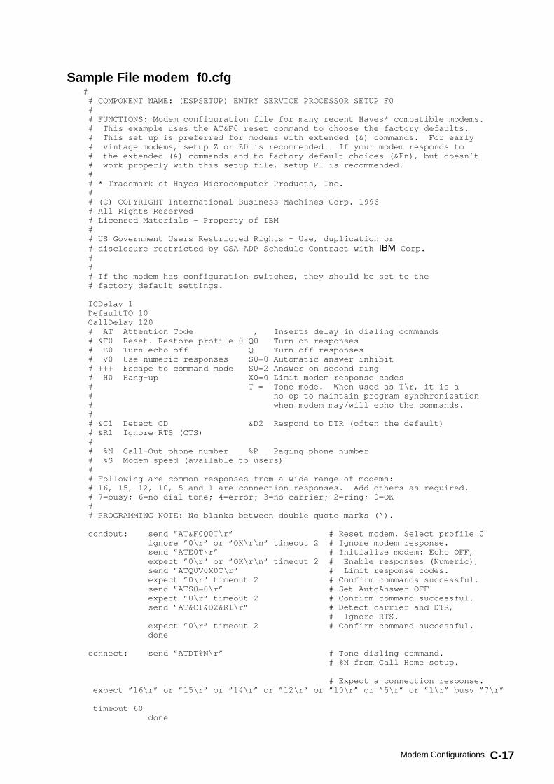
C-17Modem Configurations
Sample File modem_f0.cfg # # COMPONENT_NAME: (ESPSETUP) ENTRY SERVICE PROCESSOR SETUP F0 # # FUNCTIONS: Modem configuration file for many recent Hayes* compatible modems. # This example uses the AT&F0 reset command to choose the factory defaults. # This set up is preferred for modems with extended (&) commands. For early # vintage modems, setup Z or Z0 is recommended. If your modem responds to # the extended (&) commands and to factory default choices (&Fn), but doesn’t # work properly with this setup file, setup F1 is recommended. # # * Trademark of Hayes Microcomputer Products, Inc. # # (C) COPYRIGHT International Business Machines Corp. 1996 # All Rights Reserved # Licensed Materials – Property of IBM # # US Government Users Restricted Rights – Use, duplication or # disclosure restricted by GSA ADP Schedule Contract with IBM Corp. # # # If the modem has configuration switches, they should be set to the # factory default settings. ICDelay 1 DefaultTO 10 CallDelay 120 # AT Attention Code , Inserts delay in dialing commands # &F0 Reset. Restore profile 0 Q0 Turn on responses # E0 Turn echo off Q1 Turn off responses # V0 Use numeric responses S0=0 Automatic answer inhibit # +++ Escape to command mode S0=2 Answer on second ring # H0 Hang–up X0=0 Limit modem response codes # T = Tone mode. When used as T\r, it is a # no op to maintain program synchronization # when modem may/will echo the commands. # # &C1 Detect CD &D2 Respond to DTR (often the default) # &R1 Ignore RTS (CTS) # # %N Call–Out phone number %P Paging phone number # %S Modem speed (available to users) # # Following are common responses from a wide range of modems: # 16, 15, 12, 10, 5 and 1 are connection responses. Add others as required. # 7=busy; 6=no dial tone; 4=error; 3=no carrier; 2=ring; 0=OK # # PROGRAMMING NOTE: No blanks between double quote marks (”). condout: send ”AT&F0Q0T\r” # Reset modem. Select profile 0 ignore ”0\r” or ”OK\r\n” timeout 2 # Ignore modem response. send ”ATE0T\r” # Initialize modem: Echo OFF, expect ”0\r” or ”OK\r\n” timeout 2 # Enable responses (Numeric), send ”ATQ0V0X0T\r” # Limit response codes. expect ”0\r” timeout 2 # Confirm commands successful. send ”ATS0=0\r” # Set AutoAnswer OFF expect ”0\r” timeout 2 # Confirm command successful. send ”AT&C1&D2&R1\r” # Detect carrier and DTR, # Ignore RTS. expect ”0\r” timeout 2 # Confirm command successful. done connect: send ”ATDT%N\r” # Tone dialing command. # %N from Call Home setup. # Expect a connection response. expect ”16\r” or ”15\r” or ”14\r” or ”12\r” or ”10\r” or ”5\r” or ”1\r” busy ”7\r”
timeout 60 done

C-18 Escala PL820R User’s Guide
retry: send ”A/” # Repeat the previous command. # Expect a connection response. expect ”16\r” or ”15\r” or ”14\r” or ”12\r” or ”10\r” or ”5\r” or ”1\r” busy ”7\r”
timeout 60 done disconnect: delay 2 # Separate from previous data. send ”+++” # Assure command mode. delay 2 # Allow mode switching delay. send ”ATH0T\r” # Set modem switch–hook down # (i.e., hang up). ignore ”0\r” or ”OK\r” timeout 2 # Ignore modem response. send ”ATE0Q1\r” # Initialize modem: Echo OFF, # Disable responses. ignore ”0\r” timeout 1 done condin: send ”AT&F0Q0T\r” # Reset modem. Select profile 0 ignore ”0\r” or ”OK\r\n” timeout 2 # Ignore modem response. send ”ATE0T\r” # Initialize modem: Echo OFF, expect ”0\r” or ”OK\r\n” timeout 2 # Enable responses (Numeric), send ”ATQ0V0X0T\r” # Limit response codes. expect ”0\r” timeout 2 # Confirm commands successful. send ”ATS0=2\r” # Set AutoAnswer ON expect ”0\r” timeout 2 # Confirm command successful. send ”AT&C1&D2&R1\r” # Detect carrier and DTR, # Ignore RTS. expect ”0\r” timeout 2 # Confirm command successful. done waitcall: ignore ”2\r” timeout 1 # Ignore first ring. expect ”2\r” timeout 10 # Pick up second ring # or timeout. # Expect a connection response. expect ”16\r” or ”15\r” or ”14\r” or ”12\r” or ”10\r” or ”5\r” or ”1\r” timeout 60 done page: send ”ATDT%N,,,,%R;\r” # %N = pager call center number # Add enough commas to wait for # time to enter paging number. # %R = paging number # Confirm successful command. expect ”0\r” timeout 60 delay 2 # Wait before hanging up. send ”ATH0T\r” # Hang up. expect ”0\r” timeout 2 # Confirm successful command. done ripo: send ”AT&F0Q0T\r” # Reset modem. Select profile 0 ignore ”0\r” or ”OK\r\n” timeout 2 # Ignore modem response. send ”ATE0T\r” # Initialize modem: Echo OFF, expect ”0\r” or ”OK\r\n” timeout 2 # Enable responses (Numeric), send ”ATQ0V0X0T\r” # Limit response codes. expect ”0\r” timeout 2 # Confirm commands successful. send ”ATS0=0\r” # Set AutoAnswer OFF expect ”0\r” timeout 2 # Confirm command successful. send ”AT&C1&D2&R1\r” # Detect carrier and DTR, # Ignore RTS. expect ”0\r” timeout 2 # Confirm command successful. done # RI Power On enabled. error: # Handle unexpected modem # responses. expect ”8\r” or ”7\r” or ”6\r” or ”4\r” or ”3\r” delay 2 done

C-19Modem Configurations
Sample File modem_f1.cfg # # COMPONENT_NAME: (ESPSETUP) ENTRY SERVICE PROCESSOR SETUP F1 # # FUNCTIONS: Modem configuration file for many recent Hayes* compatible modems. # This example uses the AT&F1 reset command to choose the factory defaults. # This set up is for modems with extended (&) commands and which do not work # properly with setup F0. For early vintage modems, setup Z or Z0 is # recommended. # # * Trademark of Hayes Microcomputer Products, Inc. # # (C) COPYRIGHT International Business Machines Corp. 1996 # All Rights Reserved # Licensed Materials – Property of IBM # # US Government Users Restricted Rights – Use, duplication or # disclosure restricted by GSA ADP Schedule Contract with IBM Corp. # # # If the modem has configuration switches, they should be set to the # factory default settings. ICDelay 1 DefaultTO 10 CallDelay 120 # AT Attention Code , Inserts delay in dialing commands # &F1 Reset. Restore profile 1 Q0 Turn on responses # E0 Turn echo off Q1 Turn off responses # V0 Use numeric responses S0=0 Automatic answer inhibit # +++ Escape to command mode S0=2 Answer on second ring # H0 Hang–up X0=0 Limit modem response codes # T = Tone mode. When used as T\r, it is a # no op to maintain program synchronization # when modem may/will echo the commands. # # &C1 Detect CD &D2 Respond to DTR (often the default) # &R1 Ignore RTS (CTS) # # %N Call–Out phone number %P Paging phone number # %S Modem speed (available to users) # # Following are common responses from a wide range of modems: # 16, 15, 12, 10, 5 and 1 are connection responses. Add others as required. # 7=busy; 6=no dial tone; 4=error; 3=no carrier; 2=ring; 0=OK # # PROGRAMMING NOTE: No blanks between double quote marks (”). condout: send ”AT&F1Q0T\r” # Reset modem. Select profile 1 ignore ”0\r” or ”OK\r\n” timeout 2 # Ignore modem response. send ”ATE0T\r” # Initialize modem: Echo OFF, expect ”0\r” or ”OK\r\n” timeout 2 # Enable responses (Numeric), send ”ATQ0V0X0T\r” # Limit response codes. expect ”0\r” timeout 2 # Confirm commands successful. send ”ATS0=0\r” # Set AutoAnswer OFF expect ”0\r” timeout 2 # Confirm command successful. send ”AT&C1&D2&R1\r” # Detect carrier and DTR, # Ignore RTS. expect ”0\r” timeout 2 # Confirm command successful. done connect: send ”ATDT%N\r” # Tone dialing command. # %N from Call Home setup. # Expect a connection response. expect ”16\r” or ”15\r” or ”14\r” or ”12\r” or ”10\r” or ”5\r” or ”1\r” busy ”7\r”
timeout 60

C-20 Escala PL820R User’s Guide
done retry: send ”A/” # Repeat the previous command. # Expect a connection response. expect ”16\r” or ”15\r” or ”14\r” or ”12\r” or ”10\r” or ”5\r” or ”1\r” busy ”7\r”
timeout 60 done disconnect: delay 2 # Separate from previous data. send ”+++” # Assure command mode. delay 2 # Allow mode switching delay. send ”ATH0T\r” # Set modem switch–hook down # (i.e., hang up). ignore ”0\r” or ”OK\r” timeout 2 # Ignore modem response. send ”ATE0Q1\r” # Initialize modem: Echo OFF, # Disable responses. ignore ”0\r” timeout 1 done condin: send ”AT&F1Q0T\r” # Reset modem. Select profile 1 ignore ”0\r” or ”OK\r\n” timeout 2 # Ignore modem response. send ”ATE0T\r” # Initialize modem: Echo OFF, expect ”0\r” or ”OK\r\n” timeout 2 # Enable responses (Numeric), send ”ATQ0V0X0T\r” # Limit response codes. expect ”0\r” timeout 2 # Confirm commands successful. send ”ATS0=2\r” # Set AutoAnswer ON expect ”0\r” timeout 2 # Confirm command successful. send ”AT&C1&D2&R1\r” # Detect carrier and DTR, # Ignore RTS. expect ”0\r” timeout 2 # Confirm command successful. done waitcall: ignore ”2\r” timeout 1 # Ignore first ring. expect ”2\r” timeout 10 # Pick up second ring # or timeout. # Expect a connection response. expect ”16\r” or ”15\r” or ”14\r” or ”12\r” or ”10\r” or ”5\r” or ”1\r” timeout 60 done page: send ”ATDT%N,,,,%R;\r” # %N = pager call center number # Add enough commas to wait for # time to enter paging number. # %R = paging number # Confirm successful command. expect ”0\r” timeout 60 delay 2 # Wait before hanging up. send ”ATH0T\r” # Hang up. expect ”0\r” timeout 2 # Confirm successful command. done ripo: send ”AT&F1Q0T\r” # Reset modem. Select profile 1 ignore ”0\r” or ”OK\r\n” timeout 2 # Ignore modem response. send ”ATE0T\r” # Initialize modem: Echo OFF, expect ”0\r” or ”OK\r\n” timeout 2 # Enable responses (Numeric), send ”ATQ0V0X0T\r” # Limit response codes. expect ”0\r” timeout 2 # Confirm commands successful. send ”ATS0=0\r” # Set AutoAnswer OFF expect ”0\r” timeout 2 # Confirm command successful. send ”AT&C1&D2&R1\r” # Detect carrier and DTR, # Ignore RTS. expect ”0\r” timeout 2 # Confirm command successful. done # RI Power On enabled. error: # Handle unexpected modem # responses. expect ”8\r” or ”7\r” or ”6\r” or ”4\r” or ”3\r”

C-21Modem Configurations
delay 2 done

C-22 Escala PL820R User’s Guide

Index X-1
Index
Numbers7318 server service aid, 6-39
Aabout this book, viiaccessing system error log information, 2-4acoustical, noise, emissions, A-2adding
FRUs, 1-11serviceable event comments, 1-10
AIX documentation, 5-5, 5-7alter/display bootlist, 6-15attention LED, 2-5
HMC, 2-5automatic call home
disposal, recycling, A-1overview, 1-7
BBIST, 3-15boot list, 5-4boot mode menu, 3-12
testing, 3-23, 3-27, 3-35, B-2
Cchange diagnostic run–time, 6-16change general access password, 3-6change privileged access password, 3-6configuration
client, 5-8modem
customizing files, C-3file selection, C-1specific files, C-1
NIM server, 5-7service processor, serial port, B-3
configurations, modem, C-1configure
memory, 3-33processor, 3-33
configure scan dump policy, 6-11console mirroring, 3-36
enable/disable, 3-6customer account setup menu, 3-28customizing files, modem, configuration, C-3
Ddeconfigure
memory, 3-33processor, 3-33
diaggetrto command, 6-16diagnostic run–time
change, 6-16display, 6-16
diagnosticsconsiderations, 5-1loading, 5-6, 7-3
online, 5-2concurrent mode, 5-4, 5-5loading, 5-5, 7-1
problem determination, loading, 8-5running, service mode, 5-3service mode, 5-2standalone, 5-5, 5-6
considerations, 5-6loading, 7-2NIM server, 5-7
stopping, 7-4using, 5-1
diagsetrto command, 6-16disable, unattended start mode, 3-10disable console mirroring, 3-6display diagnostic run–time, 6-16display fault indicators, 6-22display identify indicators, 6-30display/alter bootlist, 6-15documentation, AIX, 5-5, 5-7DVD–RAM, 2-7
hot–swap removal and replacement, 2-7media drive removal, 2-7media drive replacement, 2-9
Eerror log information, accessing system, 2-4error logs, service processor, 3-37extended error data, 1-10, 6-22
FFibre Channel RAID service aids, 6-23file selection, modem, configuration, C-1firmware, 3-32
level, 3-32update, 3-32
firmware updates, system, 3-32flash SK–NET FDDI firmware, 6-23FRU, updating information, 1-11FRU LEDs
activating, 1-11deactivating, 1-11
FRUsadding, 1-11replacing, 1-11
full system partition, 1-3
Ggeneral user menu, 3-3
activating and deactivating FRU LEDs, 1-11operation, verifying, 7-1problem determination, 8-1verification, considerations, 1-2, 1-3, 7-1
HHMC
attention LED, 2-5logical partitions, 1-2, 1-3

X-2 ESCALA PL820R User’s Guide
powering off, 2-2powering on and off, 2-2resetting the system attention LED, 2-5system profiles, 1-3types of partitions, 1-3
HMC system, resetting attention LED, 2-5HMC, using small real mode memory, 1-4
Iidentify indicators, 6-30indicators, 6-22information, reference, 1-1introducing the system, 1-1
Kkeys
numeric 1, 2-6numeric 5, 2-6numeric 6, iv, 2-7, 3-23
LLCD progress indicator log, 3-38LED, control, menu, 3-19loading
online diagnostics, 7-1standalone diagnostic, 7-2
local area network service aid, 6-31log repair action service aid, 6-31logical partitions, 1-3LPAR environment
extended error data, 1-10memory considerations, 1-5memory placement, 1-5
Mmedia drive removal, 2-7media drive replacement, 2-9memory
configure, 3-33deconfigure, 3-33
memory configuration/deconfiguration menu, 3-17memory considerations, LPAR environment, 1-5memory placement, 1-5memory usage, 1-3memory, small real mode, 1-4menu
boot mode, 3-12, 3-23, 3-27customer account setup, 3-28general, user, 3-3l3 mode, 3-21, 3-23LED control, 3-4, 3-19memory configuration/deconfiguration, 3-17modem configuration, 3-24OS surveillance, setup, 3-6power control network utilities, 3-18privileged, user, 3-4processor configuration/deconfiguration, 3-15reboot/restart policy setup, 3-11remote I/O (RIO) link speed set up, 3-22ring indicate, 3-11serial port selection, 3-25serial port speed setup, 3-25setup, 3-5
system information, 3-14system power control, 3-10telephone setup, 3-26
menusaccessing service processor, 3-1service processor, 3-1
modemconfiguration
customizing files, C-3file selection, C-1specific files, C-1
configurations, C-1modem session, transfer, C-5modem_f.cfg, sample file, C-15modem_f0.cfg, sample file, C-17modem_f1.cfg, sample file, C-19modem_z.cfg, sample file, C-11modem_z0.cfg, sample file, C-13
Nnetwork service aid, 6-31NIM server
configuration, 5-7client, 5-8
standalone diagnostics, 5-7noise emissions, acoustical, A-2non–HMC attached system error accessing, 2-5notices, iii
Oonline diagnostics
concurrent mode, 5-4, 5-5loading, 5-5, 7-1modes of operation, 5-2service mode, 5-2
operating considerations, online and standalonediagnostics, 5-1
operation, online and standalone diagnostics,verifying, 7-1
operational phases, service processor, 3-39operator panel, 2-3OS defined restart policy, 3-11overview, 1-1
general, change, 3-6logical, 1-3memory usage, 1-3overview, 1-2privileged, change, 3-6profiles, 1-2service focal point, 1-6service processor, service mode, 1-4, 3-28system, 1-1system profiles, 1-3types, 1-3, 3-5
Pphysical disk status, SCSI RAID, 6-36POST indicators, 2-6POST keys, 2-6
numeric 1, 2-6numeric 5 key, 2-6numeric 6 key, 2-7
power control network utilities menu, 3-18

Index X-3
power–on, methods, 3-29power–on self–test, 2-6power–on self–test keys, 2-6powering off, using HMC, 2-2powering off and on, 2-1powering on, using HMC, 2-2preface, viiprimary console, C-6privileged user menus, 3-4problem determination
diagnostics, loading, 8-1, 8-5online, diagnostics, 8-5standalone, diagnostics, 8-5using online diagnostics, 8-1using standalone diagnostics, 8-1
processorconfigure, 3-33deconfigure, 3-33
processor configuration/deconfiguration menu,3-15
product disposal, A-1profiles, 1-2
system, 1-3publications, related, vii
Rreading the operator panel display, 2-3reboot/restart policy setup menu, 3-11recovery
procedures, C-5strategy, C-6
recycling, A-1reference information, 1-1related publications, viiremoval and replacement
starting the system, 2-1stopping the system without an HMC, 2-2
removal, media drive, 2-7repair log service aid, 6-31replacement, media drive, 2-9replacing, FRUs, 1-11reset fault indicators, 6-22resetting the system attention LED, 2-5
HMC, 2-5restart policy
OS defined, 3-11supplemental, 3-12
restart recovery, 3-30RETAIN, 3-28retries, 3-27ring indicate power–on menu, 3-11run exercisers, 6-32running online diagnostics with no attached HMC,
5-3running standalone diagnostics with no attached
HMC, iii, iv, 5-6modem, configurations, C-1
Sscan dump policy, 6-11scan log dump policy, 3-8SCSI RAID physical disk status and vital product
data, 6-36
self–test, power–on, 2-6serial port
selection menu, 3-25snoop setup menu, 3-7speed setup menu, 3-25
service aids7318 service aid, 6-39add resource, 6-3analyze adapter internal log, 6-4certify media, 6-4change hardware VPD, 6-7configure dials and LPF Keys, 6-7configure ISA adapter, 6-8configure reboot policy, 6-8configure remote maintenance policy, 6-9configure surveillance policy, 6-12create customized configuration diskette, 6-12delete resource, 6-12disk to disk copy, 6-13disk–based diagnostic, 6-37display configuration and resource list, 6-14display firmware device node information, 6-14display hardware error report, 6-14display hardware VPD, 6-14display microcode level, 6-20display or change diagnostic run–time options,
6-15display previous diagnostic results, 6-17display resource attributes, 6-17display service hints, 6-17display software product data, 6-17display system environmental sensors, 6-18display test patterns, 6-19display USB Devices, 6-19display/alter bootlist, 6-15display/alter sector, 6-13download microcode, 6-20Fibre Channel RAID service aids, 6-23flash SK–NET FDDI firmware, 6-23format media, 6-24generic microcode download, 6-26introduction, 6-1local area network, 6-31log repair action, 6-14, 6-31PCI RAID physical disk identify, 6-31periodic diagnostics, 6-31process supplemental media, 6-32ring indicate power on policy, 6-11run diagnostics, 6-32run error log analysis, 6-32run exercisers, 6-32, 6-35SCSD tape drive, 6-36SCSI bus analyzer, 6-35spare sector availability, 6-37update system or service processor flash, 6-38
service focal pointactivating and deactivating FRU LEDs, 1-11adding FRUs, 1-7, 1-11closing a serviceable event, 1-10enabling surveillance notifications, 1-8overview, 1-6replacing FRUs, 1-10, 1-11serviceable events, 1-8

X-4 ESCALA PL820R User’s Guide
setting up surveillance, 1-7settings, 1-7testing error reporting, 1-7updating FRU information, 1-11viewing and adding serviceable event
comments, 1-10viewing error details, 1-9viewing service processor error details, 1-10viewing serviceable event details, 1-9viewing serviceable event partition information,
1-11viewing serviceable events, 1-9
service processor, 3-1access
local, 3-1remote, 3-2
boot mode menu, 3-12test, 3-23, 3-27, 3-35
checklist, B-1console mirroring, 3-36customer account setup menu, 3-28error logs, 3-37general user menu, 3-3, 3-4, 3-23memory configuration/deconfiguration menu,
3-17menus, 3-1modem configuration menu, 3-24monitoring – surveillance, 3-34operational phases, 3-39OS surveillance setup menu, 3-6
service mode, 3-5, 3-28power control network utilities menu, 3-18privileged user menus, 3-4procedures in service mode, 3-28processor configuration/deconfiguration menu,
3-15reboot/restart policy setup menu, 3-11reboot/restart recovery, 3-30ring indicate power–on menu, 3-11serial port, configuration, B-3serial port selection menu, 3-25serial port snoop setup menu, 3-7serial port speed setup menu, 3-25settings, 3-2setup, B-1setup checklist, B-1setup menu, 3-5system information menu, 3-14system power control menu, 3-10telephone setup menu, 3-26test, B-1
serviceable event, viewing partition information,1-11
serviceable eventsadding comments, 1-10selecting and viewing, 1-9updating FRU information, 1-11viewing comments, 1-10viewing details, 1-9viewing error details, 1-9viewing service processor error details, 1-10working with, 1-8
set identify indicators, 6-30setup and test, service processor, B-1
setup menu, 3-5small real mode, 1-4specifc files, modem, configuration, C-1standalone diagnostics, 5-5, 5-6
loading, 7-2NIM server, 5-7, 5-8
stopping, diagnostics, 7-4stopping the system without an HMC, 2-2supplemental restart policy, 3-12surveillance, monitoring, 3-34system
attention LED, 2-4non–HMC attached system error accessing,
1-2, 1-3, 2-5powering off and on, 2-1resetting attention LED, 2-5types of partitions, 1-3verification
additional, 7-4running, 7-3
system attention indicators, 6-30system firmware updates, 3-32system information menu, 3-14system introduction, 1-1system management services, 4-1
boot devices, select, 4-11boot options, select, 4-8error log, view, 4-3exiting SMS, 4-13IPL, remote setup, 4-4IPL, setup, 4-4multiboot startup, 4-3, 4-13SCSI settings, change, 4-8select console, 4-8select language, 4-2settings, display current, 4-13settings, restore default, 4-13
system power control menu, 3-10system power–on methods, 3-29system,, stopping without an HMC, 2-2system, powering off, using HMC, 2-2system, powering on, using HMC, 2-2system, starting, 2-1
Ttelephone setup menu, 3-26terminal emulators, C-5terminal type, identifying, 5-2testing the setup, B-2transfer of a modem session, C-5
Uunattended start mode, 3-10updating, FRU information, 1-11using HMC, powering on and off, 2-2
Vverification, system, additional, 7-4verification, system, 7-3verifying, hardware operation, 7-1viewing
serviceable event comments, 1-10serviceable event details, 1-9

Index X-5
serviceable event error details, 1-9, 1-10serviceable event partition information, 1-11
vital product data, SCSI RAID, 6-36
Wweb sites
AIX documentation, 5-5, 5-7
firmware updates, 3-32microcode updates, 3-32

X-6 ESCALA PL820R User’s Guide

Vos remarques sur ce document / Technical publication remark form
Titre / Title : Bull ESCALA PL 820R User’s Guide
Nº Reférence / Reference Nº : 86 A1 20EG 01 Daté / Dated : June 2003
ERREURS DETECTEES / ERRORS IN PUBLICATION
AMELIORATIONS SUGGEREES / SUGGESTIONS FOR IMPROVEMENT TO PUBLICATION
Vos remarques et suggestions seront examinées attentivement.Si vous désirez une réponse écrite, veuillez indiquer ci-après votre adresse postale complète.
Your comments will be promptly investigated by qualified technical personnel and action will be taken as required.If you require a written reply, please furnish your complete mailing address below.
NOM / NAME : Date :
SOCIETE / COMPANY :
ADRESSE / ADDRESS :
Remettez cet imprimé à un responsable BULL ou envoyez-le directement à :
Please give this technical publication remark form to your BULL representative or mail to:
BULL CEDOC357 AVENUE PATTONB.P.2084549008 ANGERS CEDEX 01FRANCE

Technical Publications Ordering FormBon de Commande de Documents Techniques
To order additional publications, please fill up a copy of this form and send it via mail to:Pour commander des documents techniques, remplissez une copie de ce formulaire et envoyez-la à :
BULL CEDOCATTN / Mr. L. CHERUBIN357 AVENUE PATTONB.P.2084549008 ANGERS CEDEX 01FRANCE
Phone / Téléphone : +33 (0) 2 41 73 63 96FAX / Télécopie +33 (0) 2 41 73 60 19E–Mail / Courrier Electronique : [email protected]
Or visit our web sites at: / Ou visitez nos sites web à:http://www.logistics.bull.net/cedochttp://www–frec.bull.com http://www.bull.com
CEDOC Reference #No Référence CEDOC
QtyQté
CEDOC Reference #No Référence CEDOC
QtyQté
CEDOC Reference #No Référence CEDOC
QtyQté
_ _ _ _ _ _ _ _ _ [ _ _ ] _ _ _ _ _ _ _ _ _ [ _ _ ] _ _ _ _ _ _ _ _ _ [ _ _ ]
_ _ _ _ _ _ _ _ _ [ _ _ ] _ _ _ _ _ _ _ _ _ [ _ _ ] _ _ _ _ _ _ _ _ _ [ _ _ ]
_ _ _ _ _ _ _ _ _ [ _ _ ] _ _ _ _ _ _ _ _ _ [ _ _ ] _ _ _ _ _ _ _ _ _ [ _ _ ]
_ _ _ _ _ _ _ _ _ [ _ _ ] _ _ _ _ _ _ _ _ _ [ _ _ ] _ _ _ _ _ _ _ _ _ [ _ _ ]
_ _ _ _ _ _ _ _ _ [ _ _ ] _ _ _ _ _ _ _ _ _ [ _ _ ] _ _ _ _ _ _ _ _ _ [ _ _ ]
_ _ _ _ _ _ _ _ _ [ _ _ ] _ _ _ _ _ _ _ _ _ [ _ _ ] _ _ _ _ _ _ _ _ _ [ _ _ ]
_ _ _ _ _ _ _ _ _ [ _ _ ] _ _ _ _ _ _ _ _ _ [ _ _ ] _ _ _ _ _ _ _ _ _ [ _ _ ]
[ _ _ ] : no revision number means latest revision / pas de numéro de révision signifie révision la plus récente
NOM / NAME : Date :
SOCIETE / COMPANY :
ADRESSE / ADDRESS :
PHONE / TELEPHONE : FAX :
E–MAIL :
For Bull Subsidiaries / Pour les Filiales Bull :
Identification:
For Bull Affiliated Customers / Pour les Clients Affiliés Bull :
Customer Code / Code Client :
For Bull Internal Customers / Pour les Clients Internes Bull :
Budgetary Section / Section Budgétaire :
For Others / Pour les Autres :
Please ask your Bull representative. / Merci de demander à votre contact Bull.


BULL CEDOC357 AVENUE PATTONB.P.2084549008 ANGERS CEDEX 01FRANCE
86 A1 20EG 01ORDER REFERENCE
PLA
CE
BA
R C
OD
E IN
LO
WE
RLE
FT
CO
RN
ER

Utiliser les marques de découpe pour obtenir les étiquettes.Use the cut marks to get the labels.
86 A1 20EG 01
User’s Guide
ESCALA PL820R
86 A1 20EG 01
User’s Guide
ESCALA PL820R
86 A1 20EG 01
User’s Guide
ESCALA PL820R