
D20 I/O Drawer Installation Guide -...
65
Bull D20 I/O Drawer Installation Guide 86 A1 39EG 01 ORDER REFERENCE
Transcript of D20 I/O Drawer Installation Guide -...

Bull D20 I/O DrawerInstallation Guide
86 A1 39EG 01ORDER REFERENCE


Bull D20 I/O DrawerInstallation Guide
Hardware
May 2003
BULL CEDOC357 AVENUE PATTONB.P.2084549008 ANGERS CEDEX 01FRANCE
86 A1 39EG 01ORDER REFERENCE

The following copyright notice protects this book under the Copyright laws of the United States of Americaand other countries which prohibit such actions as, but not limited to, copying, distributing, modifying, andmaking derivative works.
Copyright Bull S.A. 2002, 2003
Printed in France
Suggestions and criticisms concerning the form, content, and presentation ofthis book are invited. A form is provided at the end of this book for this purpose.
To order additional copies of this book or other Bull Technical Publications, youare invited to use the Ordering Form also provided at the end of this book.
Trademarks and Acknowledgements
We acknowledge the right of proprietors of trademarks mentioned in this book.
AIX� is a registered trademark of International Business Machines Corporation, and is being used underlicence.
UNIX is a registered trademark in the United States of America and other countries licensed exclusively throughthe Open Group.
Linux is a registered trademark of Linus Torvalds.
The information in this document is subject to change without notice. Groupe Bull will not be liable for errorscontained herein, or for incidental or consequential damages in connection with the use of this material.

Contents
Safety Notices . . . . . . . . . . . . . . . . . . . . . . . . . . . . . . . . . . vRack Safety Instructions . . . . . . . . . . . . . . . . . . . . . . . . . . . . . . vElectrical Safety . . . . . . . . . . . . . . . . . . . . . . . . . . . . . . . . . viLaser Safety Information . . . . . . . . . . . . . . . . . . . . . . . . . . . . . . vii
Laser Compliance . . . . . . . . . . . . . . . . . . . . . . . . . . . . . . . vii
Data Integrity and Verification . . . . . . . . . . . . . . . . . . . . . . . . . . . ix
About This Book . . . . . . . . . . . . . . . . . . . . . . . . . . . . . . . . xiISO 9000 . . . . . . . . . . . . . . . . . . . . . . . . . . . . . . . . . . . . xiHighlighting . . . . . . . . . . . . . . . . . . . . . . . . . . . . . . . . . . . xiReferences to AIX Operating System . . . . . . . . . . . . . . . . . . . . . . . . . xiRelated Publications. . . . . . . . . . . . . . . . . . . . . . . . . . . . . . . . xiTrademarks . . . . . . . . . . . . . . . . . . . . . . . . . . . . . . . . . . . xi
Chapter 1. Setting Up the D20 I/O Drawer . . . . . . . . . . . . . . . . . . . . . . . 1Step 1. Check Your Inventory . . . . . . . . . . . . . . . . . . . . . . . . . . . . 1Step 2. Need Help? . . . . . . . . . . . . . . . . . . . . . . . . . . . . . . . . 3Step 3. Read the Safety Notices . . . . . . . . . . . . . . . . . . . . . . . . . . . 3Step 4. Read the Rack Safety Instructions . . . . . . . . . . . . . . . . . . . . . . . . 4
Rack Safety Instructions . . . . . . . . . . . . . . . . . . . . . . . . . . . . . 4Step 5. Remove the Shipping Brackets . . . . . . . . . . . . . . . . . . . . . . . . . 5Step 6. Read the D20 I/O Drawer Cabling Precautions . . . . . . . . . . . . . . . . . . . 6Step 7. Attach the Mounting Hardware to the Rack Enclosure . . . . . . . . . . . . . . . . 6Step 8. Install the D20 I/O Drawer into the Rack Enclosure . . . . . . . . . . . . . . . . . 14Step 9. Install the Cable Management Arm . . . . . . . . . . . . . . . . . . . . . . . 17Step 10. Are All of the Internal Options Installed?. . . . . . . . . . . . . . . . . . . . . 18Step 11. Verify the System and System Firmware Levels . . . . . . . . . . . . . . . . . . 18Step 12. Connect the RIO-G and SPCN Cables to the D20 I/O Drawer and to Your System . . . . . 18Step 13. Connect the Adapter Cables . . . . . . . . . . . . . . . . . . . . . . . . . 18Step 14. Are You Using the Rack Indicator Feature? . . . . . . . . . . . . . . . . . . . 19Step 15. Connect the Power Cables to the I/O Drawer . . . . . . . . . . . . . . . . . . . 19Step 16. Attach the External Signal and Power Cables to the I/O Drawer Cable Management Arm . . 20Step 17. Connect the Power Cables to Electrical Outlets . . . . . . . . . . . . . . . . . . 21Step 18. Complete the I/O Drawer Installation . . . . . . . . . . . . . . . . . . . . . . 21
Chapter 2. Installing Options in the D20 I/O Drawer . . . . . . . . . . . . . . . . . . . 23Safety Considerations . . . . . . . . . . . . . . . . . . . . . . . . . . . . . . . 23Handling Static-Sensitive Devices . . . . . . . . . . . . . . . . . . . . . . . . . . 24Options and Task List . . . . . . . . . . . . . . . . . . . . . . . . . . . . . . . 24Powering the System On and Off . . . . . . . . . . . . . . . . . . . . . . . . . . 24
Using the Hardware Management Console to Power On and Off the System . . . . . . . . . 24Operating the System Without an HMC Attached . . . . . . . . . . . . . . . . . . . . 25
Placing Your D20 I/O Drawer into the Service Position . . . . . . . . . . . . . . . . . . . 26Returning the D20 I/O Drawer to the Operating Position . . . . . . . . . . . . . . . . . . 27Service Access Cover . . . . . . . . . . . . . . . . . . . . . . . . . . . . . . . 28Front Bezel. . . . . . . . . . . . . . . . . . . . . . . . . . . . . . . . . . . 29
Removal . . . . . . . . . . . . . . . . . . . . . . . . . . . . . . . . . . . 29Replacement . . . . . . . . . . . . . . . . . . . . . . . . . . . . . . . . . 30
PCI Adapters . . . . . . . . . . . . . . . . . . . . . . . . . . . . . . . . . . 30Hot-Plug Disk Drives . . . . . . . . . . . . . . . . . . . . . . . . . . . . . . . 30LEDs . . . . . . . . . . . . . . . . . . . . . . . . . . . . . . . . . . . . . 30
iii

Appendix A. Communications Statements . . . . . . . . . . . . . . . . . . . . . . 31Federal Communications Commission (FCC) Statement . . . . . . . . . . . . . . . . . . 31European Union (EU) Statement . . . . . . . . . . . . . . . . . . . . . . . . . . . 31International Electrotechnical Commission (IEC) Statement . . . . . . . . . . . . . . . . . 31United Kingdom Telecommunications Safety Requirements . . . . . . . . . . . . . . . . . 31Avis de conformité à la réglementation d’Industrie Canada . . . . . . . . . . . . . . . . . 32
Industry Canada Class A Emission Compliance Statement . . . . . . . . . . . . . . . . 32VCCI Statement . . . . . . . . . . . . . . . . . . . . . . . . . . . . . . . . . 32Electromagnetic Interference (EMI) Statement - Taiwan . . . . . . . . . . . . . . . . . . 32Radio Protection for Germany . . . . . . . . . . . . . . . . . . . . . . . . . . . . 32
Appendix B. Environmental Notices . . . . . . . . . . . . . . . . . . . . . . . . . 35Product Recycling and Disposal . . . . . . . . . . . . . . . . . . . . . . . . . . . 35
Appendix C. Notices . . . . . . . . . . . . . . . . . . . . . . . . . . . . . . . 37
Appendix D. System Records . . . . . . . . . . . . . . . . . . . . . . . . . . . 39Identification Numbers. . . . . . . . . . . . . . . . . . . . . . . . . . . . . . . 39Device Records . . . . . . . . . . . . . . . . . . . . . . . . . . . . . . . . . 39
Options . . . . . . . . . . . . . . . . . . . . . . . . . . . . . . . . . . . 40SCSI IDs and Bay Locations . . . . . . . . . . . . . . . . . . . . . . . . . . . 41
Appendix E. D20 I/O Drawer Removal from Rack . . . . . . . . . . . . . . . . . . . . 43I/O Drawer Removal . . . . . . . . . . . . . . . . . . . . . . . . . . . . . . . 43
Index . . . . . . . . . . . . . . . . . . . . . . . . . . . . . . . . . . . . . 45
iv D20 I/O Drawer Installation Guide

Safety Notices
A danger notice indicates the presence of a hazard that has the potential of causing death or seriouspersonal injury. Danger notices appear on the following pages:
v vi
v 3
v 23
A caution notice indicates the presence of a hazard that has the potential of causing moderate or minorpersonal injury. Caution notices appear on the following pages:
v vi
v vii
v 3
v 14
v 19
v 23
Note: For a translation of these notices, see System Unit Safety Information, order number SA23-2652.
Rack Safety Instructionsv Do not install this unit in a rack where the internal rack ambient temperatures will exceed 40 degrees C.
v Do not install this unit in a rack where the air flow is compromised. Any side, front or back of the unitused for air flow through the unit must not be in direct contact with the rack.
v Care should be taken to ensure that a hazardous condition is not created due to uneven mechanicalloading when installing this unit in a rack. If the rack has a stabilizer it must be firmly attached beforeinstalling or removing this unit.
v Consideration should be given to the connection of the equipment to the supply circuit so thatoverloading of circuits does not compromise the supply wiring or overcurrent protection. To provide thecorrect power connection to the rack, refer to the rating labels located on the equipment in the rack todetermine the total power requirement for the supply circuit.
v An electrical outlet that is not correctly wired could place hazardous voltage on the metal parts of thesystem or the devices that attach to the system. It is the responsibility of the customer to ensure thatthe outlet is correctly wired and grounded to prevent an electrical shock.
v

Electrical SafetyObserve the following safety instructions any time you are connecting or disconnecting devices attached tothe workstation.
In the system you are about to setup or service:
v The ac power interface connector is considered the main power disconnect device.
v This system has redundant power supply capabilities, meaning that it has the ability to have two powersupplies running simultaneously in the same system unit. When instructed to disconnect the powersource, ensure that all power cables have been unplugged.
DANGER
An electrical outlet that is not correctly wired could place hazardous voltage on metal parts ofthe system or the devices that attach to the system. It is the responsibility of the customer toensure that the outlet is correctly wired and grounded to prevent an electrical shock.
Before installing or removing signal cables, ensure that the power cables for the system unitand all attached devices are unplugged.
When adding or removing any additional devices to or from the system, ensure that the powercables for those devices are unplugged before the signal cables are connected. If possible,disconnect all power cables from the existing system before you add a device.
Use one hand, when possible, to connect or disconnect signal cables to prevent a possibleshock from touching two surfaces with different electrical potentials.
During an electrical storm, do not connect cables for display stations, printers, telephones, orstation protectors for communications lines.D05
CAUTION:This product is equipped with a three-wire power cable and plug for the user’s safety. Use thispower cable with a properly grounded electrical outlet to avoid electrical shock.C01
DANGER
To prevent electrical shock hazard, disconnect all power cables from the electrical outlet beforerelocating the system.D01
vi D20 I/O Drawer Installation Guide

Laser Safety Information
CAUTION:This product may contain a CD-ROM, DVD-ROM, or laser module on a PCI card, which are class 1laser products.C30
Laser ComplianceAll lasers are certified in the U.S. to conform to the requirements of DHHS 21 CFR Subchapter J for class1 laser products. Outside the U.S., they are certified to be in compliance with the IEC 825 (first edition1984) as a class 1 laser product. Consult the label on each part for laser certification numbers andapproval information.
CAUTION:All laser modules are designed so that there is never any human access to laser radiation above aclass 1 level during normal operation, user maintenance, or prescribed service conditions. Dataprocessing environments can contain equipment transmitting on system links with laser modulesthat operate at greater than class 1 power levels. For this reason, never look into the end of anoptical fiber cable or open receptacle. Only trained service personnel should perform theinspection or repair of optical fiber cable assemblies and receptacles.C25, C26
Safety Notices vii

viii D20 I/O Drawer Installation Guide

Data Integrity and VerificationThese computer systems contain mechanisms designed to reduce the possibility of undetected datacorruption or loss. This risk, however, cannot be eliminated. Users who experience unplanned outages,system failures, power fluctuations or outages, or component failures must verify the accuracy of operationsperformed and data saved or transmitted by the system at or near the time of the outage or failure. Inaddition, users must establish procedures to ensure that there is independent data verification before relyingon such data in sensitive or critical operations. Users should periodically check our support websites forupdated information and fixes applicable to the system and related software.
ix

x D20 I/O Drawer Installation Guide

About This Book
This book provides information about the D20 I/O drawer, specifically how to set up and cable the I/Oexpansion drawer, install and remove options, and verify system operations.
ISO 9000ISO 9000 registered quality systems were used in the development and manufacturing of this product.
HighlightingThe following highlighting conventions are used in this book:
Bold Identifies commands, subroutines, keywords, files, structures, directories, and other itemswhose names are predefined by the system. Also identifies graphical objects such as buttons,labels, and icons that the user selects.
Italics Identifies parameters whose actual names or values are to be supplied by the user.
Monospace Identifies examples of specific data values, examples of text similar to what you might seedisplayed, examples of portions of program code similar to what you might write as aprogrammer, messages from the system, or information you should actually type.
References to AIX Operating System
Note: This document may contain references to the AIX operating system. If you are using anotheroperating system, consult the appropriate documentation for that operating system.
This document may describe hardware features and functions. While the hardware supports them,the realization of these features and functions depends upon support from the operating system.AIX provides this support. If you are using another operating system, consult the appropriatedocumentation for that operating system regarding support for those features and functions.
Related PublicationsThe following publications provide additional information about your system:
v The Site Preparation Guide for Rack Systsems, order number 86 A1 30PX, contains information to help you planyour installation.
v The System Unit Safety Information, order number 86 X1 11WD, contains translations of safety informationused throughout this book.
xi

xii D20 I/O Drawer Installation Guide

Chapter 1. Setting Up the D20 I/O Drawer
Note: This document may contain references to the AIX operating system. If you are using anotheroperating system, consult the appropriate documentation for that operating system.
This document may describe hardware features and functions. While the hardware supports them,the implementation of these features and functions depends upon support from the operatingsystem. AIX provides this support. If you are using another operating system, consult theappropriate documentation for that operating system regarding support for those features andfunctions.
To set up your D20 I/O drawer, follow the procedures in this chapter.
Step 1. Check Your Inventory
h Books, CD-ROM and Other Media h ″About Your Machine″ Document
h Power Cables (1 standard, 2 optional) hD20 I/O Drawer
h RIO-G Cables (Depending on configuration, quantity 1 or2)
h System Power Control Network (SPCN) Cables(Depending on configuration, quantity 1 or 2)
h Rack-Mounting Template h 2 Rail Assemblies
1
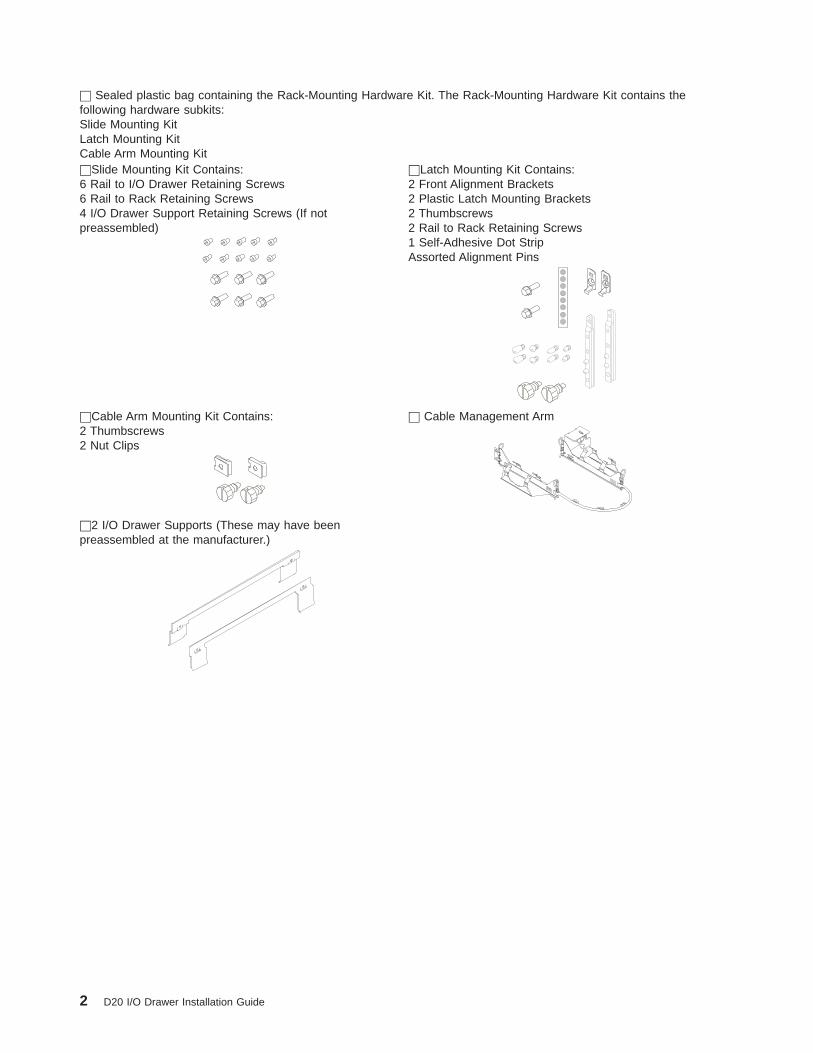
h Sealed plastic bag containing the Rack-Mounting Hardware Kit. The Rack-Mounting Hardware Kit contains thefollowing hardware subkits:Slide Mounting KitLatch Mounting KitCable Arm Mounting KithSlide Mounting Kit Contains:6 Rail to I/O Drawer Retaining Screws6 Rail to Rack Retaining Screws4 I/O Drawer Support Retaining Screws (If notpreassembled)
hLatch Mounting Kit Contains:2 Front Alignment Brackets2 Plastic Latch Mounting Brackets2 Thumbscrews2 Rail to Rack Retaining Screws1 Self-Adhesive Dot StripAssorted Alignment Pins
hCable Arm Mounting Kit Contains:2 Thumbscrews2 Nut Clips
h Cable Management Arm
h2 I/O Drawer Supports (These may have beenpreassembled at the manufacturer.)
2 D20 I/O Drawer Installation Guide

Step 2. Need Help?If you encounter difficulties while setting up your I/O drawer unit, contact your sales representative forassistance.
Step 3. Read the Safety NoticesBefore continuing, read the following safety information. Do not plug any cables into the system, adapters,or electrical outlets until you have reviewed this information. Make sure none of the power cables areconnected before continuing to the next step.
In the I/O drawer you are about to set up:
v The ac power-interface connector is considered the main power disconnect device.
v This I/O drawer has redundant power supply capabilities, in that it has the ability to have two powersupplies running simultaneously in the same I/O drawer. When instructed to disconnect the powersource, ensure that all power cables have been unplugged.
DANGER
An electrical outlet that is not correctly wired could place hazardous voltage on metal parts ofthe system or the devices that attach to the system. It is the responsibility of the customer toensure that the outlet is correctly wired and grounded to prevent an electrical shock.
Before installing or removing signal cables, ensure that the power cables for the system unitand all attached devices are unplugged.
When adding or removing any additional devices to or from the system, ensure that the powercables for those devices are unplugged before the signal cables are connected. If possible,disconnect all power cables from the existing system before you add a device.
Use one hand, when possible, to connect or disconnect signal cables to prevent a possibleshock from touching two surfaces with different electrical potentials.
During an electrical storm, do not connect cables for display stations, printers, telephones, orstation protectors for communications lines.D05
CAUTION:This product is equipped with a three-wire power cable and plug for the user’s safety. Use thispower cable with a properly grounded electrical outlet to avoid electrical shock.C01
DANGER
To prevent electrical shock hazard, disconnect all power cables from the electrical outlet beforerelocating the system.D01
Chapter 1. Setting Up the I/O Drawer 3

Step 4. Read the Rack Safety InstructionsBefore continuing, make sure you review the following instructions for mounting the I/O drawer into therack. If the I/O drawer was shipped already mounted in a rack, go to Chapter 2, “Installing Options in theD20 I/O Drawer”, on page 23.
Rack Safety Instructionsv Do not install this unit in a rack where the ambient temperatures will exceed 35 degrees C.
v Do not install this unit in a rack where the airflow is compromised. Any side, front or back of the unitused for air flow through the unit must not be in indirect contact with the rack.
v Ensure that a hazardous condition is not created due to uneven mechanical loading when installing thisunit in a rack. If the rack has a stabilizer it must be firmly attached before installing or removed this unit.
v Consider the connection of the equipment to the supply circuit so that the overloaded circuits do notcompromise the supply wiring or over-current protection.
v An electrical outlet that is not correctly wired could place hazardous voltage on the metal parts of thesystem or the devices that attach to the system. It is the responsibility of the customer to ensure thatthe outlet is correctly wired and grounded to prevent an electrical shock.
When installing the D20 I/O drawer, you will need the following items:
v Rack-Mounting Template
v 2 Drawer Rail Assemblies
v Cable Management Arm
v Rack-Mounting Hardware Kit
v Screwdriver
4 D20 I/O Drawer Installation Guide

Step 5. Remove the Shipping BracketsIf your D20 I/O drawer was shipped preinstalled in a rack, you may want to remove the shipping bracketsfrom the rear rack EIA rails. The shipping brackets keep the rear of the I/O drawer from moving in aside-to-side motion while being transported. They can, however, remain on the rack without interfering withnormal day-to-day operations. To remove them, do the following:
1. Go the the rear of the rack and open the rack’s rear door.
2. Remove the two screws that secure each shipping bracket to the rack’s EIA rails. See the followingillustration.
3. After removing the shipping brackets, reinstall the four retaining screws.
1 Rack EIA Rails2 Shipping Bracket Retaining Screws and the Rear Rail to Rack Retaining
Screws3 Shipping Brackets
Chapter 1. Setting Up the I/O Drawer 5

Step 6. Read the D20 I/O Drawer Cabling PrecautionsBefore installing the D20 I/O drawer into the rack and connecting the RIO-G and power control cables, dothe following:
1. Ensure that your system is running the latest level firmware. For information about checking orupgrading the firmware level of your system, refer to the firmware updates section of your system’sinstallation guide
2. After ensuring that your firmware is at the latest level, turn off the power and disconnect the systemunit’s power cables from the power source.
Step 7. Attach the Mounting Hardware to the Rack EnclosureBefore performing this procedure, read through each step and study the illustrations.
Attention: Mounting the rails is a complex procedure. To install the rack rails correctly, you must read,and then perform each procedure step in the order given. Failure to do so may cause rail failure.
Note: If your rack has doors, remove the doors at this time. For information about removing the rackdoors, refer to your rack installation guide.
Locate the hardware-mounting kit, rack-mounting template, and the I/O drawer rails that wereshipped with your I/O drawer.
1 Rack-Mounting Template2 Rack-Mounting Hardware Kit3 I/O Drawer Rail Assemblies
6 D20 I/O Drawer Installation Guide

To mount the rails into the system rack, do the following:
Note: Unless otherwise noted, all instructions assume that you are in front of and facing the system rack.
1. Locate the rack-mounting template. If you do not have a rack-mounting template, go to step 3.
Notes:
a. The rack-mounting template has printed illustrations located on the front and rear of the template.Each illustration is designed to aid you in identifying the EIA (Electronics Industries Association)location holes used when planning to populate your rack. Do not use the rack-mounting templatewithout reading and understanding the following steps.
b. Each step must be completed in its entirety. Skipping steps or not following steps in sequence maycause rail failure.
c. Use the front side of the rack-mounting template when installing the hardware on the front of therack, and the back side of the rack-mounting template when installing the hardware on the back ofthe rack. You can distinguish the front of the template from the rear by the step numbers. Thesteps on the front of the rack-mounting template begin with the number 1.
d. The D20 I/O drawer requires 4 EIA units of free space.
2. When using the rack-mounting template, be aware of the following:
v Each black or white unit on the template is equal to 1 EIA unit.
v Each EIA unit consists of three holes.
v The EIA units illustrated on the template must be aligned with an EIA units located on the rack.
v It is not necessary to align like-colored EIA units. For example, a black EIA unit illustrated on therack-mounting template does not have to be aligned with a black EIA unit located on the rack. Ablack EIA unit on the rack-mounting template can be aligned with a white EIA unit located on therack. See the following illustration.
To use the rack-mounting template, do the following:
a. Locate and unpack the rack-mounting hardware kit. This kit contains all the hardware necessary tomount the rails to your rack. In the rack-mounting hardware kit, locate and then unpack thelatch-mounting kit.
b. Locate the self-adhesive dot strip, packaged in the latch-mounting kit.
c. Determine where in the rack to place the drawer. Make note of the EIA location number. Align theblack and white strip located on each side of the rack-mounting template with an EIA location oneach side of the rack. Note the EIA number located across from the rack-mounting template ears.When you are positioning the rack-mounting template on the rack’s rear EIA rails, you will bealigning the rack-mounting template ears across from the same numbers.
d. Remove the protective coating from each adhesive strip located on the back ears of therack-mounting template. Lightly press the template into position onto the rack EIA rails. Ensure thatthe rack-mounting template is level.
Chapter 1. Setting Up the I/O Drawer 7

e. Note the four dots printed on the front side of the template. Attach a self-adhesive dot directlyacross from the template’s printed dots onto the rack’s EIA rail.
f. Remove the rack-mounting template from the front of the rack. You should now have placed fourself-adhesive dots, four pieces of tape, or four marks on your rack’s front EIA rails.
g. Go to the rear of the rack.
h. Turn over the template. The first step printed on the template should now start with a number otherthan 1.
i. Facing the rear of the rack, remove the protective coating from each adhesive strip, and attach therack-mounting template to the back of the rack. Place the template on the corresponding EIAlocations that were noted from the front of the rack.
j. Note the four dots printed on the template. Attach a self-adhesive dot or mark directly across fromthe template’s printed dots onto the rack’s EIA rail.
Note: When attaching the self-adhesive dots on the rack’s rear EIA rail, fold the dots around theEIA rail, as shown on the template and in the following illustration. If you do not have theself-adhesive dots, wrap a piece of tape around the rail. The self-adhesive dot, or the tapewrapped around the EIA rail, will aid you when aligning the rear rail-alignment pins to therear rail EIA holes.
1 Folded Self-Adhesive Dots
k. Notice the nut clips printed on the upper left side of the rack-mounting template. The nut clips arepackaged in the cable arm mounting kit. Locate the cable arm mounting kit in the rack-mountinghardware kit.
l. Install the nut clips around the EIA holes indicated by the template. The nut clips will aid you in thesecuring of the cable management arm to the rack’s EIA rail.
8 D20 I/O Drawer Installation Guide

1 Nut Clip and Nut Clip Placement2 Self-Adhesive Dot Placement
m. Remove the rack-mounting template, then continue to step 6. You should now have placed fourself-adhesive dots, four pieces of tape, or four marks on your rack’s rear EIA rails. You should alsohave placed two nut clips on your rack’s rear left EIA rail.
3. If you do not have a rack-mounting template, do the following:
Note: An EIA unit on the rack consists of a grouping of three holes. Each EIA unit may be separatedby either a color or a line. The drawer you are about to install measures 4 EIA units high.
a. Determine where in the rack to place the I/O drawer, and make note of the EIA location numbers.
The following illustration shows 1 EIA unit and 4 EIA units. Depending on the rack manufacturer,the EIA units may be separated either by color or by a line. Note that the holes along the rack’sEIA rail are not evenly spaced. If your rack has no color or line separation between EIA units,assume that each EIA unit begins where the hole spacing is closest together.
1 EIA Hole Spacing2 Self-Adhesive Dot Placement
b. Facing the front of the rack and working from the right side, locate the bottom EIA unit into whichthe drawer will be installed. Place a supplied self-adhesive dot, piece of tape, or mark next to thetop hole of this EIA unit.
Note: The self-adhesive dots, piece of tape, or mark are used to identify the EIA unit holes locatedon the rack’s EIA rail. Alignment pins located on the rail-alignment brackets are placedthrough the identified holes when mounting the rails. If you no longer have any of the dots,use some other form of marking tool to aid you in identifying the hole locations (for example,pieces of tape, or a marker).
Chapter 1. Setting Up the I/O Drawer 9

c. Place another self-adhesive dot or mark next to the bottom hole of the EIA unit directly above.
d. Repeat steps a through c to corresponding holes located on the rack’s left-side EIA rail. You shouldnow have placed four self-adhesive dots, four pieces of tape, or four marks on your rack’s front EIArails.
4. Go to the rear of the rack.
5. Standing in front of and facing the rear of the rack, do the following:
a. From the right side of the rack, locate and select the same EIA units that were noted on the front ofthe rack.
Note: Marks or self-adhesive dots should wrap around the rear EIA rails. Visibly seeing the dots,tape, or marks when installing the rails, from the front of the rack, will simplify the aligning ofthe rear-rail alignment pins to the correct rack EIA rail holes.
b. Place a mark or self-adhesive dot in the middle hole of the bottom EIA unit.
c. Place a mark or self-adhesive dot in the middle hole of the EIA unit directly above.
d. Repeat steps b and c to locate the correct EIA holes for the left side.
e. Locate and unpack the rack-mounting hardware kit. This kit contains all the hardware necessary tomount the rails to your rack.
f. Working on the left side of the rack, do the following:
1) Locate, and then install a nut clip around the top hole of the third EIA unit from the bottom. Thenut clips can be found in the rack-mounting hardware kit. See the following illustration.
2) Install a second nut clip around the middle hole of the fourth EIA unit from the bottom. See thefollowing illustration.
1 EIA Hole Spacing2 Self-Adhesive Dot Placement
Note: The nut clips will be used to secure the cable-management arm to the rack’s EIA rail.
10 D20 I/O Drawer Installation Guide

6. Select the two front-alignment brackets.
1 System Rack2 Front-Alignment Bracket3 Thumbscrew
7. Mount the front-alignment brackets. Place each alignment pin through one of the rack EIA holesidentified by the self-adhesive dots, tape, or marker.
Note: If the preassembled alignment pins, located on the front and rear alignment brackets, do not fitinto the rack EIA holes, do the following:
a. Using a screwdriver, remove the preinstalled alignment pins from the front-alignmentbrackets.
b. Locate the correct-size alignment pins that were shipped with the rack-mounting hardwarekit.
c. Install the newly selected alignment pins into the front-alignment brackets. Ensure that thereplaced alignment pins are mounted into the correct alignment bracket holes.
8. Secure the front-alignment brackets to the rack’s EIA rails with thumbscrews that were supplied in therack-mounting hardware kit. Ensure that both alignment brackets are aligned on the same EIA unit.See the previous illustration.
9. Unpack both rails.
Note: The I/O drawer rails are front-to-back and left-to-right side dependent.
10. Separate the left rail from the right rail. Rails are labeled L and R. When standing in front of andfacing the rack, the L denotes the left rail, and R denotes the right rail.
11. Install the rails into the rack, as follows:
Note: The installation procedure for the left and right rails is identical.
a. Select the left rail. Put the rail into the correct orientation by doing the following:
1) Position the rail so that the preassembled alignment bracket is facing the rear of the rack.
Chapter 1. Setting Up the I/O Drawer 11

2) The top of the preassembled alignment bracket must be facing up and in the same orientationas the front alignment brackets. See the following illustration.
1 Left Rail 4 Rear Alignment Pins2 Right Rail 5 Front Rail-Mounting Flange3 Rear Alignment Bracket 6 Left Label (L)
3) Rail lengths were preset by the manufacturer. If the preset rail length is incorrect for your rack,loosen but do not remove, the three retaining screws that secure the rail-length adjusting plateto the rail.
Note: Loosen the screws only enough to make an adjustment to the rail length. To accessthese screws, you must extend the inner rails.
1 Rail Adjustment Plate2 Retaining Screws for Rail-Length Adjusting Plate
12 D20 I/O Drawer Installation Guide

4) If necessary, adjust the rail to the correct length for your rack. After the rail is set to the correctlength, tighten all previously loosened adjusting-plate screws.
b. Standing in front of the rack, install the left rail’s rear alignment pins into the appropriate holesidentified by the self-adhesive dots, tape, or marker that you previously attached to your rack’srear EIA rail.
c. Swing the front rail-retaining flange into the forked section of the front-alignment bracket, makingsure that the two middle slots fit around the two front-alignment pins.
Note: Do not swing the front rail flange in between the front-alignment bracket and the rack’s EIArail.
1 Left Rail 5 Latch-Mounting Bracket2 Rack EIA Rail 6 Front Alignment Pins3 Front-Alignment Bracket 7 Rail-Retaining Screw4 Thumbscrew 8 Front Rail-Retaining Flange
d. Insert, and then tighten one of the rail to rack-retaining screws and one of the latch-mountingbrackets into the threaded screw hole located above the two alignment pins.
e. To install the right rail, repeat steps a through d.
f. Remove the two thumbscrews from both front alignment brackets.
g. Ensure that the rails are level from front to back and from left to right.
Notes:
1) The front left and right rails should now have the two upper-retaining screws in place.
2) The front lower rail and four rear-rack retaining screws will be added while performing Step 8.Install the D20 I/O Drawer into the Rack Enclosure.
Chapter 1. Setting Up the I/O Drawer 13

Step 8. Install the D20 I/O Drawer into the Rack Enclosure
Attention: When installing the I/O expansion drawer into a rack, ensure that a hazardous condition isnot created due to uneven mechanical loading. If your rack uses a stabilizer bar, it must be firmly attachedbefore installing or removing this I/O drawer.
To mount the D20 I/O drawer into the rack, do the following:
1. If you have not already done so, remove the D20 I/O expansion drawer from the box.
2. Ensure that the I/O drawer supports have been attached to the left and right sides of your I/O drawer.See the following illustration.
Note: The plastic drawer supports are used to stabilize and hold the I/O drawer in the correctlyaligned position when it is mounted onto the rails.
1 Left and Right I/O Drawer Supports2 Lifting Handles
3. If the I/O drawer supports are not already attached to the sides of the I/O drawer, secure each I/Odrawer support with two retaining screws. Attach one of the I/O drawer supports to each side of theI/O drawer as shown in the above illustration.
4. Place the rails into the service position. The rails are placed into the service position by pulling outthe two telescoping sections of each rail. Each section of rail makes a clicking sound when fullyextended and placed into the service position.
5. You are now ready to mount your D20 I/O drawer. Before continuing to the next step, be sure to readand understand the following caution notices:
CAUTION:The stabilizer must be firmly attached to the bottom front of the rack to prevent the rack fromturning over when the drawers are pulled out of the rack. Do not pull out or install any draweror feature if the stabilizer is not attached to the rack.C16
CAUTION:This unit weighs between 32 kg (70.5 pounds) and 55 kg (121.2 pounds). Three persons arerequired to safely move it. Using less than three persons to move it can result in injury.C05
6. Using three persons, grasp the two handles located on each side of the I/O drawer.
7. Lift the I/O drawer and position it on the extended rails.
8. Align the threaded screw holes located on the I/O drawer to the rail clearance holes.
14 D20 I/O Drawer Installation Guide

9. Beginning with the middle screw hole on each side of the I/O drawer, insert and then tighten the threeretaining screws through each rail, as shown in the following illustration.
1 Rail to Drawer Retaining Screws (Qty. 6)
10. Remove the drawer supports from each side of the I/O drawer.
Note: In case of future I/O drawer removal, you may want to store the drawer supports.
11. Simultaneously release the safety latches, and push the I/O drawer into the rack.
Note: To unlock the rails, lift the left safety release latch up and push the right safety release latchdown.
1 D20 I/O Drawer 4 Stabilizing Bar2 19 Inch Rack 5 Front Rack Door3 Extension Rail Safety Release Latch 6 I/O Drawer Release Latch
12. Slide the I/O drawer in and out of the rack one or two times. This action allows the I/O drawer to alignthe rails to itself.
Note: After the I/O drawer rails are installed, do not extend them past their safety latches. Thesafety-release latches stop the rails from overextending and separating.
Chapter 1. Setting Up the I/O Drawer 15

13. With the D20 I/O drawer fully retracted in the rack, go to the rear of the rack and install two retainingscrews between each alignment pin. Tighten all four screws at this time.
14. Go to the front of the rack.
15. Pull the D20 I/O drawer approximately halfway out of the rack, and install the two lower frontrail-retaining screws as shown in the following illustration.
1 Left Rail 5 Front-Alignment Pins2 Rack EIA Rail 6 Lower Front Rail-Retaining Screw3 Front-Alignment Bracket 7 Left Rail4 Latch-Mounting Bracket
16. If you are planning to move the rack a short distance after installing the drawer (for example, acrossthe room), use the two supplied thumbscrews to secure the I/O drawer to the rack enclosure. If youare planning to move the rack any greater distance than across the room, contact your servicerepresentative.
1 D20 I/O Drawer2 Thumbscrew
16 D20 I/O Drawer Installation Guide

Step 9. Install the Cable Management ArmTo install the cable management arm, do the following:
1. Locate the two nut clips that you attached to the back of the rack.
2. Insert two thumbscrews through each nut clip, securing the cable carrier-support bracket to the back ofthe rack.
3. Place the two snap buttons, located on the cable management arm, into the unlocked (pulled out)position.
4. Align the cable management arm with the bracket assembled on the back of the I/O drawer chassis.Insert the two snap buttons into the bracket holes.
5. Push in on the head of the snap buttons, securing them to the bracket located on the chassis. See thefollowing illustration.
1 Nut Clips 3 Snap Buttons (Qty. 2)2 Thumbscrews (Qty. 2) 4 Cable Management Arm
Chapter 1. Setting Up the I/O Drawer 17

Step 10. Are All of the Internal Options Installed?These instructions are for I/O drawers that have internal options (such as adapters, disk drives, or memoryupgrades) already installed.
If you have internal options that are not installed, install them now. Refer to Chapter 2, “Installing Optionsin the D20 I/O Drawer”, on page 23, and then return here.
Step 11. Verify the System and System Firmware LevelsPrior to attaching the RIO-G and system power control cables, review the following and then perform thenecessary actions indicated:
1. If the system unit to which you are connecting the D20 I/O drawer has its RIO connectors covered witha metal plate or sealed from easy access, do not attempt to attach any cables between the system unitand the D20 I/O drawer. A feature upgrade may be necessary; contact your service representative.
2. Ensure that your system is running the latest level firmware. For information about checking orupgrading the firmware level on your system, refer to the firmware updates section of your system’sinstallation guide
3. After ensuring that your firmware is at the latest level, turn off the power and disconnect the system’spower cables from the power source.
Step 12. Connect the RIO-G and SPCN Cables to the D20 I/O Drawerand to Your SystemFor information on cabling the D20 I/O drawer to your system, refer to your system’s installation guide.
Step 13. Connect the Adapter Cables
Note: Before doing this step, read and understand “Step 3. Read the Safety Notices” on page 3.
You can install up to seven PCI adapters into each I/O drawer. When adding or replacing PCI adapters,note the following:
v If you are using any optional adapters (such as token ring or 8-port EIA-232), connect the cables to theappropriate adapter connectors in the PCI slots of your machine.
v For the locations of installed adapters, consult the ″About Your Machine″ document.
v Refer to the PCI Adapter Placement Reference, order number SA23-2504, for a list of PCI adaptersavailable for your system.
v Before installing any PCI adapter, refer to PCI Adapter Placement Reference, order number SA23-2504,to ensure that there are no slot restrictions placed on that the adapter by your system.
The following illustration shows the possible PCI adapter slots and connector locations on the back of theD20 I/O drawer.
18 D20 I/O Drawer Installation Guide

Step 14. Are You Using the Rack Indicator Feature?The rack indicator feature signals when a drawer installed in a rack has a failure. If you are unsurewhether you are using the rack indicator feature, ask your system administrator.
Connect the rack indicator cable as shown in the following illustration.
Step 15. Connect the Power Cables to the I/O DrawerPlug the power cables into the D20 I/O drawer.
Notes:
1. This I/O drawer could be equipped with two power supplies. Each power supply needs its own powercable.
2. If your I/O drawer is equipped with one power supply, connect the power cable to the powerreceptacle. A second power receptacle is available when a second (redundant) power supply has beenadded to the I/O drawer. See the following illustration.
1 Power Supply 1 Cable2 Power Supply 2 Cable
CAUTION:This product is equipped with a three-wire power cable and plug for the user’s safety. Use thispower cable with a properly grounded electrical outlet to avoid electrical shock.C01
CAUTION:This unit weighs between 32 kg (70.5 pounds) and 55 kg (121.2 pounds). Three persons arerequired to safely move it. Using less than three persons to move it can result in injury.C05
Chapter 1. Setting Up the I/O Drawer 19

Step 16. Attach the External Signal and Power Cables to the I/ODrawer Cable Management ArmTo attach the external cables to the cable management arm, do the following:
1. Put the I/O drawer into the service position. Refer to “Placing Your D20 I/O Drawer into the ServicePosition” on page 26.
Note: The rails lock in the fully extended position with a click.
1 Cable-Management Arm Trays
2. Loosely place the cables into the two cable-management arm trays.
Note: Power cables should be routed through the ring located next to the cable-management armsnap buttons.
3. Slide the drawer in and out of the rack a few times. Ensure that the cables and cable managementarm move freely, without creating kinks in the cables.
4. Use cable ties to secure the cables to the cable management arm.
20 D20 I/O Drawer Installation Guide

Step 17. Connect the Power Cables to Electrical OutletsConnect the D20 I/O drawer power cables from the power supplies to the power source (for example, anelectrical outlet or power distribution panel).
When connected to the power source, the green LED located on the D20 I/O drawer operator panelbegins to blink.
When the power-on sequence is complete, the power LED on the operator panel stops blinking andremains on.
The following illustration shows the operator panel and the locations of the power and attention LEDs.
1 Power LED2 Attention LED3 Operator Panel4 Snap Buttons
If your system does not stop in standby mode, check all cables for good connection. If you cannot find aproblem, call your support center for assistance.
Step 18. Complete the I/O Drawer InstallationTo complete the installation of the your I/O drawer, go to your system’s installation guide. Refer to thechapter that contains the procedures for setting up your system. After locating the system setupprocedures, do the following:
v Start Your System - The system is completely cabled and can be powered on.
v Accessing Documentation - Read and understand how to access system documentation.
v Run System Verification
Chapter 1. Setting Up the I/O Drawer 21

22 D20 I/O Drawer Installation Guide

Chapter 2. Installing Options in the D20 I/O Drawer
This chapter provides instructions to help you add options to your I/O drawer that are not covered in yoursystem installation guide.
Note: Most of the options that you can install are discussed in your system installation guide, for example,hot-plug PCI adapter installation and disk drive installation.
Safety ConsiderationsObserve the following safety precautions anytime you work with this system unit.
In the system you are about to setup or service:v The ac power interface connector is considered the main power disconnect device.v This system and your I/O drawer have independent redundant power supply capabilities, meaning that
each unit may be configured to have two power supplies running simultaneously in the same systemunit. When instructed to disconnect the power source, ensure that all power cables that run to eachservicing I/O drawer has been disconnected from the power distribution panel.
Read the following safety notices, before performing any of the following procedures.
DANGER
An electrical outlet that is not correctly wired could place hazardous voltage on metal parts ofthe system or the devices that attach to the system. It is the responsibility of the customer toensure that the outlet is correctly wired and grounded to prevent an electrical shock.
Before installing or removing signal cables, ensure that the power cables for the system unitand all attached devices are unplugged.
When adding or removing any additional devices to or from the system, ensure that the powercables for those devices are unplugged before the signal cables are connected. If possible,disconnect all power cables from the existing system before you add a device.
Use one hand, when possible, to connect or disconnect signal cables to prevent a possibleshock from touching two surfaces with different electrical potentials.
During an electrical storm, do not connect cables for display stations, printers, telephones, orstation protectors for communications lines.D05
CAUTION:This product is equipped with a three-wire power cable and plug for the user’s safety. Use thispower cable with a properly grounded electrical outlet to avoid electrical shock.C01
CAUTION:This unit has more than one power supply cord. To reduce the risk of electrical shock, disconnecttwo power supply cords before servicing.C21
23

Handling Static-Sensitive Devices
Attention: Electronic boards and disk drives are sensitive to static electricity discharge. These devicesare wrapped in antistatic bags to prevent this damage.
Take the following precautions:
v If you have an antistatic wrist strap available, use it while handling the device.
v Do not remove the device from the antistatic bag until you are ready to install the device in the system.
v With the device still in its antistatic bag, touch it to a metal frame of the system.
v Grasp cards and boards by the edges. Hold drives by the frame. Avoid touching the solder joints orpins.
v If you need to lay the device down while it is out of the antistatic bag, lay it on the antistatic bag. Beforepicking it up again, touch the antistatic bag and the metal frame of the system at the same time.
v Handle the devices carefully to prevent permanent damage.
Options and Task List
Option/Task Option/Task Name and Page Location
Adapters “PCI Adapters” on page 30
Bezel, Front “Front Bezel” on page 29
Cover “Service Access Cover” on page 28
Disk Drives “Hot-Plug Disk Drives” on page 30
Operating Position “Returning the D20 I/O Drawer to the Operating Position” on page 27
Service Position “Placing Your D20 I/O Drawer into the Service Position” on page 26
Powering the System On and OffThis section provides procedures for powering on and powering off the system.
If you have an HMC attached to your system, use “Using the Hardware Management Console to PowerOn and Off the System”.
If you do not have an HMC attached to your system, use “Operating the System Without an HMCAttached” on page 25.
Using the Hardware Management Console to Power On and Off theSystemThe system can be powered on after all of the following steps are completed:v All I/O drawer cables are connectedv Base system cables are connectedv All PCI cables to supported subsystems are connectedv The hardware management console (HMC) is connected, if requiredv Power is connected to the system
24 D20 I/O Drawer Installation Guide

After the required cables are installed, and the power cables are connected, the HMC user interfaceprovides a power-on function to turn on the power to the system. The power button on the operator panelcan be pushed to initialize the system but the preferred method is to use the HMC if booting logicalpartitions. Progress indicators, also referred to as checkpoints, are visible on the operator panel display asthe system power is turned on. The power LED on the base system stops blinking and stays on, indicatingthe system power is on.
The base system and I/O subsystems are powered on through the system power control network (SPCN).When power is applied, the power LEDs on the base system go from blinking to on continuously, and thepower LEDs on the I/O subsystem(s) come on and stay on. This indicates that power levels aresatisfactory in the subsystems.
Powering the System OffThe HMC user interface provides a power-off function to turn off the power to the system.
Also, if the system is operating in a full system partition under AIX, typing the shutdown command causesthe system to shut down and power off. The -F flag shuts down the system without warning system users.Check with the system administrator before using this command. If you cannot use this method, you canpower off the system by pressing the power button on the media subsystem operator panel.
Attention: Using the power button on the operator panel to power off the system can causeunpredictable results in the data files, and the next IPL will take longer to complete.
Operating the System Without an HMC Attached
Starting the System1. Set the power switches of the attached devices to On.
Note: When the system is plugged in but not powered on, the power LED flashes slowly.
2. If the LED is not flashing and OK is not displayed, ensure that the power cord, located at the back ofthe system unit, is plugged into a grounded electrical outlet.
3. If this does not solve the problem, contact your service representative.
4. Press the Power-On button.
When you press the Power-On button, the power LED comes on, and the system starts a POST(power-on self-test).
During POST, progress codes display in the operator panel display.
5. If the power LED does not come on and there is no indication of power when you press the Power-Onbutton, contact your service representative.
Stopping the System Unit
Attention: When you use the shutdown procedure for your system, follow the correct shutdownprocedure before you stop the system. Failure to do so can result in loss of data. The system is powereddown by the shutdown procedure.
1. At the command line, type shutdown to stop the operating system.
2. After you shut down the operating system, set the power switches of attached devices to Off.
3. If you will be servicing the system, unplug the system-unit power cable from the electrical outlet.
Chapter 2. Installing Options 25

Placing Your D20 I/O Drawer into the Service Position
Attention: When placing your D20 I/O drawer into the service position, it is essential that all stabilityplates are firmly in position to prevent the rack from toppling. Ensure that only one system drawer is in theservice position at a time.
Before doing any service actions inside your D20 I/O drawer, put the D20 I/O drawer into the serviceposition. To place the drawer into the service position, do the following:
1. Open the front rack door.
2. If your D20 I/O drawer is equipped with two blue thumbscrews securing it to the rack, remove thethumbscrews at this time. The screws are located on the bezel, just above each I/O drawer releaselatch.
1 Front Bezel2 Transport Retaining Screw for System Drawer
3. Release the I/O drawer release latches located on the left and right side.
4. Pull the system drawer out from the rack until the rails are fully extended.
Note: When the system rails are fully extended, safety latches on the slide rails lock into place. Thisprevents the system from being accidentally pulled out too far and dropped. The followingillustration shows a system drawer in the service position.
26 D20 I/O Drawer Installation Guide

1 D20 I/O Drawer 4 Stabilizing Bar2 19 Inch Rack 5 Front Rack Door3 Extension Rail Safety Release Latch 6 System Drawer Release Latch
After completing the service actions, return the D20 I/O drawer to the operating position.
Returning the D20 I/O Drawer to the Operating PositionTo return your D20 I/O drawer to the operating position, do the following:
1. Release the rail release latches located on each rail. See the illustration on page 27 for the location ofthe release latches.
Note: To release the left rail, pull the release latch up. To release the right rail, push the right latchdown.
2. Release latches must be in the open position. See the illustration on page 27 for the location of the I/Odrawer release latches.
3. Push the system drawer straight back into the rack until both release latches on the I/O drawer havelocked into position.
4. If you removed two thumbscrews from the front bezel, replace them at this time.
5. Close the front rack door.
Chapter 2. Installing Options 27

Service Access CoverBefore performing the following procedure, read the “Safety Notices” on page v.
To open the service access cover, do the following:
1. Open the front rack door and place the D20 I/O drawer into the service position as described in“Placing Your D20 I/O Drawer into the Service Position” on page 26.
2. Loosen the three captive thumbscrews located on the rear of the cover. See the following illustrationfor thumbscrew locations.
Note: The service access cover pivots on a hinge located directly behind the four cooling fans.
3. To open the service access cover, lift the cover up from the back edge. The hinges will prevent thecover from swinging more than 110 degrees into the open position.
Note: When you open the service access cover, ensure that you have enough height clearance.
4. After service is complete, close and secure the cover with the three thumbscrews located on the backflange.
Attention: For proper cooling and airflow, replace the cover before turning on the system. Operating thesystem for extended periods of time (over 30 minutes) with the cover removed might damage the systemcomponents.
1 Thumbscrews2 Service Access Cover3 D20 I/O Drawer
28 D20 I/O Drawer Installation Guide

Front BezelBefore performing the following procedure, read the “Safety Notices” on page v.
RemovalTo remove the front bezel, do the following:
1. Open the front rack door. If necessary, place the D20 I/O drawer into the service position as describedin “Placing Your D20 I/O Drawer into the Service Position” on page 26.
2. Simultaneously press in both bezel-release tabs. See the following illustration for bezel-release tablocations.
3. Pivoting the bezel from the bottom, swing the top of the bezel out.
4. Pull the bottom of the bezel up, and then away from the system chassis. This action releases the twotabs located on the bottom of the bezel.
5. Put the bezel in a safe place.
1 Rack Door 3 Bezel-Release Tab (Locatedon each side of bezel)
2 Bezel 4 19-Inch Rack
Chapter 2. Installing Options 29

ReplacementTo replace the front bezel, do the following:
1. Open the front rack door. If necessary, put the D20 I/O drawer into the service position as described in“Placing Your D20 I/O Drawer into the Service Position” on page 26.
2. Insert the two tabs located on the bottom edge of the bezel into their locking slots, located on thechassis.
3. Pivot the bezel up toward the top of the chassis.
4. Align the release tabs to the matching slots located on the front of the I/O drawer.
5. Gently push the tabs into the slots until the bezel seats against the front of the I/O drawer.
6. If the I/O drawer is in the service position, put the I/O drawer back in the operating position asdescribed in “Returning the D20 I/O Drawer to the Operating Position” on page 27.
7. Close the rack door.
PCI AdaptersBefore removing or installing a hot-plug PCI adapter, refer to your system installation guide for detailedinstructions.
Hot-Plug Disk DrivesBefore removing or installing a hot-plug disk drive, refer to your system installation guide for detailedinstructions.
LEDsFor LED definitions, refer to your system installation guide.
30 D20 I/O Drawer Installation Guide

Appendix A. Communications Statements
This appendix contains EMC and safety regulatory statements for the D20. Statements for other productsintended for use with this product appears in their accompanying documentation.
Federal Communications Commission (FCC) Statement
Note: This equipment has been tested and found to comply with the limits for a Class A digital device,pursuant to Part 15 of the FCC Rules. These limits are designed to provide reasonable protectionagainst harmful interference when the equipment is operated in a commercial environment. Thisequipment generates, uses, and can radiate radio frequency energy and, if not installed and used inaccordance with the instruction manual, may cause harmful interference to radio communications.Operation of this equipment in a residential area is likely to cause harmful interference in whichcase the user will be required to correct the interference at his own expense.
Properly shielded and grounded cables and connectors must be used in order to meet FCC emissionlimits. Neither the provider nor the manufacturer is responsible for any radio or television interferencecaused by using other than recommended cables and connectors or by unauthorized changes ormodifications to this equipment. Unauthorized changes or modifications could void the user’s authority tooperate the equipment.
This device complies with Part 15 of the FCC Rules. Operation is subject to the following two conditions:(1) this device may not cause harmful interference, and (2) this device must accept any interferencereceived, including interference that may cause undesired operation.
European Union (EU) StatementThis product is in conformity with the protection requirements of EU Council Directive 89/336/EEC on theapproximation of the laws of the Member States relating to electromagnetic compatibility. Themanufacturer cannot accept responsibility for any failure to satisfy the protection requirements resultingfrom a non-recommended modification of the product, including the fitting of option cards supplied by thirdparties. Consult with your dealer or sales representative for details on your specific hardware.
This product has been tested and found to comply with the limits for Class A Information TechnologyEquipment according to European Standard EN 55022. The limits for Class A equipment were derived forcommercial and industrial environments to provide reasonable protection against interference with licensedcommunication equipment.
Attention: This is a Class A product. In a domestic environment this product may cause radiointerference in which case the user may be required to take adequate measures.
International Electrotechnical Commission (IEC) StatementThis product has been designed and built to comply with IEC Standard 950.
United Kingdom Telecommunications Safety RequirementsThis equipment is manufactured to the International Safety Standard EN60950 and as such is approved inthe UK under the General Approval Number NS/G/1234/J/100003 for indirect connection to the publictelecommunication network.
The network adapter interfaces housed within this equipment are approved separately, each one having itsown independent approval number. These interface adapters, supplied by the manufacturer, do not use orcontain excessive voltages. An excessive voltage is one which exceeds 70.7 V peak ac or 120 V dc. They
31

interface with this equipment using Safe Extra Low Voltages only. In order to maintain the separate(independent) approval of the manufacturer’s adapters, it is essential that other optional cards, notsupplied by the manufacturer, do not use main voltages or any other excessive voltages. Seek advice froma competent engineer before installing other adapters not supplied by the manufacturer.
Avis de conformité à la réglementation d’Industrie CanadaCet appareil numérique de la classe A est conforme à la norme NMB-003 du Canada.
Industry Canada Class A Emission Compliance StatementThis Class A digital apparatus complies with Canadian ICES-003.
VCCI Statement
The following is a summary of the VCCI Japanese statement in the box above.
This is a Class A product based on the standard of the Voluntary Control Council for Interference byInformation Technology Equipment (VCCI). If this equipment is used in a domestic environment, radiodisturbance may arise. When such trouble occurs, the user may be required to take corrective actions.
Electromagnetic Interference (EMI) Statement - Taiwan
The following is a summary of the EMI Taiwan statement above.
Warning: This is a Class A product. In a domestic environment this product may cause radio interferencein which case the user will be required to take adequate measures.
Radio Protection for GermanyDieses Gerät ist berechtigt in Übereinstimmung mit Dem deutschen EMVG vom 9.Nov.92 dasEG–Konformitätszeichen zu führen.
Der Aussteller der Konformitätserklärung ist die IBM Germany.
Dieses Gerät erfüllt die Bedingungen der EN 55022 Klasse A. Für diese von Geräten gilt folgendeBestimmung nach dem EMVG:
32 D20 I/O Drawer Installation Guide

Geräte dürfen an Orten, für die sie nicht ausreichend entstört sind, nur mit besonderer Genehmigung desBundesministers für Post und Telekommunikation oder des Bundesamtes für Post und Telekommunikationbetrieben werden. Die Genehmigung wird erteilt, wenn keine elektromagnetischen Störungen zu erwartensind.
(Auszug aus dem EMVG vom 9.Nov.92, Para.3, Abs.4)
Hinweis
Dieses Genehmigungsverfahren ist von der Deutschen Bundespost noch nicht veröffentlicht worden.
Appendix A. Communications Statements 33

34 D20 I/O Drawer Installation Guide

Appendix B. Environmental Notices
Product Recycling and DisposalComponents of the system unit, such as structural parts and circuit boards, can be recycled whererecycling facilities exist. Companies are available to disassemble, reutilize, recycle, or dispose of electronicproducts. Contact your account representative for more information. This system unit contains parts suchas circuit boards, cables, electromagnetic compatibility gaskets and connectors which may contain leadand copper/beryllium alloys that require special handling and disposal at end of life. Before this unit isdisposed, these materials must be removed and recycled or discarded according to applicable regulations.This book contains specific information on each battery type where applicable.
This product may contain a sealed lead acid, nickel cadmium, nickel metal hydride, lithium, orlithium ion battery. Consult your user manual or service manual for specific battery information.The battery must be recycled or disposed of properly. Recycling facilities may not be available inyour area. For information on disposal of batteries, contact your local waste disposal facility.
35

36 D20 I/O Drawer Installation Guide

Appendix C. Notices
This information was developed for products and services offered in the U.S.A.
The manufacturer may not offer the products, services, or features discussed in this document in othercountries. Consult the manufacturer’s representative for information on the products and services currentlyavailable in your area. Any reference to the manufacturer’s product, program, or service is not intended tostate or imply that only that product, program, or service may be used. Any functionally equivalent product,program, or service that does not infringe any intellectual property right of the manufacturer may be usedinstead. However, it is the user’s responsibility to evaluate and verify the operation of any product,program, or service.
The manufacturer may have patents or pending patent applications covering subject matter described inthis document. The furnishing of this document does not give you any license to these patents. You cansend license inquiries, in writing, to the manufacturer.
The following paragraph does not apply to the United Kingdom or any country where suchprovisions are inconsistent with local law: THIS MANUAL IS PROVIDED ″AS IS″ WITHOUTWARRANTY OF ANY KIND, EITHER EXPRESSED OR IMPLIED, INCLUDING, BUT NOT LIMITED TO,THE IMPLIED WARRANTIES OF NON-INFRINGEMENT, MERCHANTABILITY OR FITNESS FOR APARTICULAR PURPOSE. Some states do not allow disclaimer of express or implied warranties in certaintransactions; therefore, this statement may not apply to you.
This information could include technical inaccuracies or typographical errors. Changes are periodicallymade to the information herein; these changes will be incorporated in new editions of the publication. Themanufacturer may make improvements and/or changes in the product(s) and/or the program(s) describedin this publication at any time without notice.
Information concerning products made by other than the manufacturer was obtained from the suppliers ofthose products, their published announcements, or other publicly available sources. The manufacturer hasnot tested those products and cannot confirm the accuracy of performance, compatibility or any otherclaims related to products made by other than the manufacturer. Questions on the capabilities of productsmade by other than the manufacturer should be addressed to the suppliers of those products.
37

38 D20 I/O Drawer Installation Guide

Appendix D. System Records
Use this appendix to keep a record of the system’s identification information.
Identification NumbersRecord and retain the following information:
Product Name D20
Serial Number
The system unit’s identification numbers are located on the front of the machine, as shown in the followingillustration:
1 Front Serial Number Location2 Rear Serial Number Location
Device RecordsUse the following tables to keep a record of the PCI adapters and hot-plug disk drives installed in yourD20. This information can be helpful when you install additional adapters or disk drives or if your systemneeds service.
39

Options
1 PCI-X Expansion Slot 1 5 PCI-X Expansion Slot 52 PCI-X Expansion Slot 2 6 PCI-X Expansion Slot 63 PCI-X Expansion Slot 3 7 PCI-X Expansion Slot 74 PCI-X Expansion Slot 4
Location Option Description
PCI-X Slot 1 ______________________________________________
PCI-X Slot 2 ______________________________________________
PCI-X Slot 3 ______________________________________________
PCI-X Slot 4 ______________________________________________
PCI-X Slot 5 ______________________________________________
PCI-X Slot 6 ______________________________________________
PCI-X Slot 7 ______________________________________________
40 D20 I/O Drawer Installation Guide

SCSI IDs and Bay Locations
Index Bay Location Drive Name SCSI ID
8 DB1 D01 Hot-Plug Disk Drive 8 - DB1
9 DB1 D02 Hot-Plug Disk Drive 9 - DB1
A DB1 D03 Hot-Plug Disk Drive A - DB1
B DB1 D04 Hot-Plug Disk Drive B - DB1
C DB1 D05 Hot-Plug Disk Drive C - DB1
D DB1 D06 Hot-Plug Disk Drive D - DB1
8 DB2 D07 Hot-Plug Disk Drive 8 - DB2
9 DB2 D08 Hot-Plug Disk Drive 9 - DB2
A DB2 D09 Hot-Plug Disk Drive A - DB2
B DB2 D10 Hot-Plug Disk Drive B - DB2
C DB2 D11 Hot-Plug Disk Drive C - DB2
D DB2 D12 Hot-Plug Disk Drive D - DB2
Appendix D. System Records 41

If you install a disk drive into your system, record the definition in the drive description field in the followingtable.
Drive Location SCSI ID Drive Description
Hot-Plug Disk Drive Disk Bay D01 SCSI ID - 8 DB1 ______
Hot-Plug Disk Drive Disk Bay D02 SCSI ID - 9 DB1 ______
Hot-Plug Disk Drive Disk Bay D03 SCSI ID - A DB1 ______
Hot-Plug Disk Drive Disk Bay D04 SCSI ID - B DB1 ______
Hot-Plug Disk Drive Disk Bay D05 SCSI ID - C DB1 ______
Hot-Plug Disk Drive Disk Bay D06 SCSI ID - D DB1 ______
Hot-Plug Disk Drive Disk Bay D07 SCSI ID - 8 DB2 ______
Hot-Plug Disk Drive Disk Bay D08 SCSI ID - 9 DB2 ______
Hot-Plug Disk Drive Disk Bay D09 SCSI ID - A DB2 ______
Hot-Plug Disk Drive Disk Bay D10 SCSI ID - B DB2 ______
Hot-Plug Disk Drive Disk Bay D11 SCSI ID - C DB2 ______
Hot-Plug Disk Drive Disk Bay D12 SCSI ID - D DB2 ______
42 D20 I/O Drawer Installation Guide

Appendix E. D20 I/O Drawer Removal from Rack
Before performing these procedures, read “Safety Notices” on page v.
CAUTION:This unit weighs between 32 kg (70.5 pounds) and 55 kg (121.2 pounds). Three persons arerequired to safely move it. Using fewer than three persons to move it can result in injury.
CAUTION:
v Removing the system drawer requires three people.
v Do not place more than one drawer in the service position at one time.
v Ensure that the system cables are not tangled and will not bind when placing the system drawerinto the service or operating positions.
I/O Drawer RemovalTo remove the I/O drawer from the rack, do the following:
1. If you have not already done so, shut down the system as described in “Powering the System On andOff” on page 24.
2. Open the front and rear rack doors.
3. Disconnect all cables from the rear of the I/O drawer drawer.
4. Disconnect the cable-management arm by pulling out the two captive snap buttons from the rear ofthe system drawer. Disconnect the bracket attached to the EIA rail by removing the two thumbscrews.
1 Nut Clips 3 Snap Buttons2 Thumbscrews 4 Cable Management Arm
43

5. Put the I/O drawer into the service position. If necessary, refer to “Placing Your D20 I/O Drawer intothe Service Position” on page 26.
6. Using four retaining screws, attach the two I/O drawer supports. If you no longer have the I/O drawersupports, contact your service representative.
1 Left and Right I/O Drawer Supports2 Lifting Handles
7. Remove the six retaining screws that secure the rails to the I/O drawer chassis.
1 Rail to Drawer Retaining Screws
8. Using three persons, grasp the system drawer handles located on each side of the system.
9. Lift the drawer up, so that the I/O drawer supports clear the rails.
10. Place the I/O drawer in a safe place.
11. Push the extended rails carefully back into the rack.
12. Close the front and rear rack doors.
44 D20 I/O Drawer Installation Guide

Index
Aaccess cover (rack) 28adapters, PCI 30
Bbattery
disposal, recycling 35bezel 29
removal 29replacement 30
Cchecklist, inventory 1covers 28
access cover (rack) 28
Ddevice records 39
internal and external options 39internal files and devices 42
disk drives, hot-plug 30
Eelectrical safety v
electrical vlaser compliance statement viirack 4
Hhandling static-sensitive devices 24highlighting xiHMC
powering off 25powering on and off 24
hot-plug disk drives 30
II/O drawer, set up 1installing options 23installing the I/O drawer 1
adapter cables 18brackets, shipping 5cable management arm 17cable management arm, attaching cables 20cabling precautions 6complete drawer installation 21connect the RIO-G cable 18connect the SPCN cable 18electrical outlets 21firmware level verification 18
installing the I/O drawer (continued)internal options 18inventory 1list, options and task 24need help 3power cables 21power cables, connect 19precautions, cabling 6rack hardware, installation 6rack indicator 19rack installation, D20 14rack mount template, installation 6rack rail, installation 6rack safety 4removal rack from 43removal, system drawer from rack 43safety notices 3shipping brackets, remove 5start system 21system level verification 18
instructions, rack safety 4internal options 18inventory 1
Llaser compliance statement viilaser safety information viiLEDs 30
Nnotices, safety 3
Ooptions installation 23
adapters, PCI 30bezel removal 29bezel replacement, 30bezels 29covers 28devices, handling static-sensitive 24disk drives, hot-plug 30operating position, 27PCI adapters 30safety considerations 23service access cover removal, 28service position, 26table, LED 30
Ppower cables 19
connect power cables to I/O drawer 19connect to outlet 21
45

powering offusing HMC 25
powering off and on 24powering on
using HMC 24product disposal 35
Rrack safety instructions vrecords, device 39recycling 35related publications xi
Ssafety considerations 23safety notices vservice position 26setting up the I/O drawer 1starting the system 25stopping the system 25system
powering off and on 24system records 39
key serial number 39machine type/model 39serial number 39
system, powering offusing HMC 25
system, powering onusing HMC 24
Ttrademarks xi
Uusing HMC
powering on and off 24
46 D20 I/O Drawer Installation Guide

Vos remarques sur ce document / Technical publication remark form
Titre / Title : Bull D20 I/O Drawer Installation Guide
Nº Reférence / Reference Nº : 86 A1 39EG 01 Daté / Dated : May 2003
ERREURS DETECTEES / ERRORS IN PUBLICATION
AMELIORATIONS SUGGEREES / SUGGESTIONS FOR IMPROVEMENT TO PUBLICATION
Vos remarques et suggestions seront examinées attentivement.Si vous désirez une réponse écrite, veuillez indiquer ci-après votre adresse postale complète.
Your comments will be promptly investigated by qualified technical personnel and action will be taken as required.If you require a written reply, please furnish your complete mailing address below.
NOM / NAME : Date :
SOCIETE / COMPANY :
ADRESSE / ADDRESS :
Remettez cet imprimé à un responsable BULL ou envoyez-le directement à :
Please give this technical publication remark form to your BULL representative or mail to:
BULL CEDOC357 AVENUE PATTONB.P.2084549008 ANGERS CEDEX 01FRANCE

Technical Publications Ordering FormBon de Commande de Documents Techniques
To order additional publications, please fill up a copy of this form and send it via mail to:Pour commander des documents techniques, remplissez une copie de ce formulaire et envoyez-la à :
BULL CEDOCATTN / Mr. L. CHERUBIN357 AVENUE PATTONB.P.2084549008 ANGERS CEDEX 01FRANCE
Phone / Téléphone : +33 (0) 2 41 73 63 96FAX / Télécopie +33 (0) 2 41 73 60 19E–Mail / Courrier Electronique : [email protected]
Or visit our web sites at: / Ou visitez nos sites web à:http://www.logistics.bull.net/cedochttp://www–frec.bull.com http://www.bull.com
CEDOC Reference #No Référence CEDOC
QtyQté
CEDOC Reference #No Référence CEDOC
QtyQté
CEDOC Reference #No Référence CEDOC
QtyQté
_ _ _ _ _ _ _ _ _ [ _ _ ] _ _ _ _ _ _ _ _ _ [ _ _ ] _ _ _ _ _ _ _ _ _ [ _ _ ]
_ _ _ _ _ _ _ _ _ [ _ _ ] _ _ _ _ _ _ _ _ _ [ _ _ ] _ _ _ _ _ _ _ _ _ [ _ _ ]
_ _ _ _ _ _ _ _ _ [ _ _ ] _ _ _ _ _ _ _ _ _ [ _ _ ] _ _ _ _ _ _ _ _ _ [ _ _ ]
_ _ _ _ _ _ _ _ _ [ _ _ ] _ _ _ _ _ _ _ _ _ [ _ _ ] _ _ _ _ _ _ _ _ _ [ _ _ ]
_ _ _ _ _ _ _ _ _ [ _ _ ] _ _ _ _ _ _ _ _ _ [ _ _ ] _ _ _ _ _ _ _ _ _ [ _ _ ]
_ _ _ _ _ _ _ _ _ [ _ _ ] _ _ _ _ _ _ _ _ _ [ _ _ ] _ _ _ _ _ _ _ _ _ [ _ _ ]
_ _ _ _ _ _ _ _ _ [ _ _ ] _ _ _ _ _ _ _ _ _ [ _ _ ] _ _ _ _ _ _ _ _ _ [ _ _ ]
[ _ _ ] : no revision number means latest revision / pas de numéro de révision signifie révision la plus récente
NOM / NAME : Date :
SOCIETE / COMPANY :
ADRESSE / ADDRESS :
PHONE / TELEPHONE : FAX :
E–MAIL :
For Bull Subsidiaries / Pour les Filiales Bull :
Identification:
For Bull Affiliated Customers / Pour les Clients Affiliés Bull :
Customer Code / Code Client :
For Bull Internal Customers / Pour les Clients Internes Bull :
Budgetary Section / Section Budgétaire :
For Others / Pour les Autres :
Please ask your Bull representative. / Merci de demander à votre contact Bull.


BULL CEDOC357 AVENUE PATTONB.P.2084549008 ANGERS CEDEX 01FRANCE
86 A1 39EG 01ORDER REFERENCE
PLA
CE
BA
R C
OD
E IN
LO
WE
RLE
FT
CO
RN
ER

Utiliser les marques de découpe pour obtenir les étiquettes.Use the cut marks to get the labels.
86 A1 39EG 01
Installation Guide
D20 I/O Drawer
86 A1 39EG 01
Installation Guide
D20 I/O Drawer
86 A1 39EG 01
Installation Guide
D20 I/O Drawer


![C R E D I T S - thetrove.is [multi]/Naruto (d20)/d20-Naruto... · This Naruto: d20 supplement is designed for use with the Naruto d20 and d20 Modern Roleplaying Game published by](https://static.fdocuments.in/doc/165x107/60afa37945ac8908e62fd7cc/c-r-e-d-i-t-s-multinaruto-d20d20-naruto-this-naruto-d20-supplement.jpg)