A modular apparatus for architectural integration of frameless solar modules

Home page | Help | Clear English | French | Spanish | German
Search | Subjects | Titles A-Z | Courses | Illustrations | Topics | e-Course builder
Contract TOC Expand Document Contract Chapter Add to e-Course Preferences
Printable version
Export document
as HTML file Help
Export document
as PDF file
Building Construction with 14 Modules (TCA; 1983; 618 pages)
1. ARCHITECTURAL DRAWING I
1.1 AIMS AND PURPOSE OF ARCHITECTURAL DRAWINGS
1.1.1 CONTENTS OF ARCHITECTURAL DRAWINGS
1.2 DRAWING EQUIPMENT
1.2.1 PENCILS
1.2.2 DRAWING PENS
1.2.3 COMPASSES
1.2.4 DRAWING BOARDS
1.2.5 T-SQUARES
1.2.6 SET SQUARES
1.2.7 PROTRACTORS
1.2.8 SCALES
1.2.9 FRENCH CURVES
1.2.10 TEMPLATES
1.2.11 DRAWING PINS AND OTHER FIXINGS
1.2.12 MINOR ITEMS OF EQUIPMENT
1.2.13 PRINTING PAPERS
1.2.14 TRACING PAPER, CLOTH AND FILM
25/09/2011 Building Construction with 14 Modules: 2. ARCHITECTURAL D…
file:///D:/temp/04/stuff.htm 1/201

1.2.15 BACKING SHEETS
1.2.16 DRAWING PAPERS
1.2.17 CARTRIDGE
1.2.18 HANDMADE AND MOULDMADE PAPERS
1.2.19 PLASTIC-COATED CARD
1.3 LETTERING
1.3.1 PRINCIPLE OF LETTERING
1.3.2 FREEHAND LETTERING
1.3.3 TYPES OF LETTERS
1.3.3.1 The Roman Alphabet
1.3.3.2 Sans Serif Letters
1.3.3.3 Inclined Lettering
1.3.3.4 Script Lettering
1.3.3.5 Stencil Lettering
1.3.3.6 Guided Pen Lettering
1.3.3.7 Pressure-Transfer Lettering
1.4 LINEWORK AND DIMENSIONING
1.4.1 TYPES OF LINES
1.4.2 PENCIL DRAWING
1.4.3 INKING - IN
1.4.4 BASIC RULES OF DIMENSIONING
1.4.4.1 Types of Dimensions
1.4.4.2 Placement of Dimensions
25/09/2011 Building Construction with 14 Modules: 2. ARCHITECTURAL D…
file:///D:/temp/04/stuff.htm 2/201

1.5 ENLARGEMENT AND REDUCTION OF LINE DRAWINGS
1.6 GEOMETRICAL CONSTRUCTIONS
1.6.1 LINES AND ANGLES
1.6.1.1 To bisect a straight line AB
1.6.1.2 To divide a straight line AB into a given number of equal parts
1.6.1.3 To divide a straight line AB into any ratio
1.6.1.4 To construct an angle of 90°
1.6.1.5 To construct an angle of 45°
1.6.1.6 To construct an angle of 60°
1.6.1.7 To construct an angle of 30°
1.6.1.8 To bisect any given angle
1.6.1.9 To construct an angle SIMILAR to a given angle
1.6.1.10 To draw a line PARALLEL to a given line
1.6.2 TRIANGLES
1.6.2.1 To construct an EQUILATERAL triangle
1.6.2.2 To construct a triangle with given BASE ANGLES and
ALTITUDE
1.6.2.3 To inscribe a circle in a given triangle ABC
1.6.2.4 To circiumscribe a triangle ABC
1.6.3 CIRCLES
1.6.3.1 Basic CIRCLE-Constructions
1.6.3.2 To draw a tangent to a point A on the circumference of a circle
centre O
25/09/2011 Building Construction with 14 Modules: 2. ARCHITECTURAL D…
file:///D:/temp/04/stuff.htm 3/201

1.6.3.3 To draw an internal tangent to two circles of equal diameter
1.6.3.4 To find the centre of a given circle arc
1.6.3.5 To join two straight lines at RIGHT ANGLES to each other by
an arc of given radius
1.6.3.6 To draw a curve of given radius joining two circles
1.6.3.7 To join two straight lines by two arcs of equal radius
1.6.4 BASIC ARCH CONSTRUCTIONS
2. ARCHITECTURAL DRAWING II
2.1 TYPES OF PROJECTIONS
2.2 ORTHOGRAPHIC PROJECTION
2.2.1 CONSTRUCTION OF ORTHOGRAPHIC PROJECTION
2.2.2 ELEVATIONS
2.2.3 PLANS AND SECTIONS
2.3 PICTORIAL DRAWING
2.3.1 AXONOMETRIC PROJECTION
2.3.2 ISOMETRIC PROJECTION
2.3.3 DIMETRIC PROJECTION
2.3.4 OBLIQUE PROJECTION
2.3.4.1 Length of Receding Lines
2.3.4.2 Construction of Oblique Drawings
2.3.4.3 Rules of Oblique Drawing
2.3.4.4 Scale of the Receding Lines
2.3.4.5 Direction of Receding Lines
25/09/2011 Building Construction with 14 Modules: 2. ARCHITECTURAL D…
file:///D:/temp/04/stuff.htm 4/201

2.3.4.6 Position of Axes
2.4 PERSPECTIVE DRAWING
2.4.1 PERSPECTIVE TERMS
2.4.2 PHENOMENA OF PERSPECTIVE DRAWING
2.4.3 SYSTEMS OF PERSPECTIVE DRAWINGS
2.4.4 METHODS OF PERSPECTIVE DRAWINGS
2.4.5 TWO-POINT PERSPECTIVE
2.4.6 ONE-POINT PERSPECTIVE
2.5 SHADES AND SHADOWS
2.5.1 THE USE OF SHADOWS
2.5.2 SHADES AND SHADOWS
2.5.3 THE CONVENTIONAL DIRECTION OF LIGHT
2.5.4 THE 45° DIRECTION
2.5.5 THE TRUE DIRECTION OF LIGHT
2.5.6 SHADOWS OF SOLIDS
2.5.7 PLANES OF SHADOW
2.5.8 PRINCIPLES OF SHADOW-CASTING
2.6 DRAWING PRACTICE
2.6.1 DRAWING SHEETS
2.6.1.1 Sizes and Folds
2.6.1.2 Layout and Identification
2.6.2 LEVELS
2.6.3 REFERENCING
25/09/2011 Building Construction with 14 Modules: 2. ARCHITECTURAL D…
file:///D:/temp/04/stuff.htm 5/201

2.6.4 ABBREVIATIONS
2.6.5 REPRESENTATION OF MATERIALS
2.6.6 GRAPHICAL SYMBOLS AND REPRESENTATION
2.6.7 HATCHING RULES
2.7 APPLICATION FOR BUILDING PERMIT
2.7.1 PROCEDURE OF APPLYING FOR PERMISSION TO ERECT A
BUILDING
2.7.2 FORMULARS
4. CONTRACT PLANNING AND SITE ORGANISATION
4.1 CONTRACT PLANNING
4.1.1 BAR CHART
4.1.2 NETWORK ANALYSIS
4.1.3 THE OVERALL PROGRAMME
4.1.3.1 Break down of job
4.1.3.2 Quantities of work and time content
4.1.3.3 Plant and Labour outputs
4.1.3.4 Sequence and timing of operations
4.1.3.5 The programme chart
4.1.4 PLANNING CONSIDERATIONS
4.1.4.1 Site conditions and access
4.1.4.2 Nature of job
4.1.4.3 Plant
4.1.4.4 Scaffolding
25/09/2011 Building Construction with 14 Modules: 2. ARCHITECTURAL D…
file:///D:/temp/04/stuff.htm 6/201

4.2 SITE ORGANIZATION
4.2.1 PRELIMINARY WORK
4.2.2 SITE PLANNING
4.2.2.1 Period planning
4.2.2.2 Weekly planning
4.2.2.3 Progress control
4.2.3 SITE LAYOUT
5. FOUNDATIONS
5.1 SOIL INVESTIGATIONS
5.1.1 SITE EXPLORATION
5.1.1.1 Trial holes
5.1.1.2 Bore holes
5.1.1.3 Sampling
5.1.1.4 Tests
5.1.1.5 Load or bearing test
5.1.2 SOILS AND SOIL CHARACTERISTICS
5.1.2.1 Rocks and soils
5.1.2.2 Stresses and pressures
5.2 EXCAVATIONS AND TIMBERING
5.3 TYPES OF FOUNDATIONS
5.3.1 CLASSIFICATION
5.3.2 CHOICE OF FOUNDATION
5.3.3 SPREAD FOUNDATIONS
25/09/2011 Building Construction with 14 Modules: 2. ARCHITECTURAL D…
file:///D:/temp/04/stuff.htm 7/201

5.3.3 SPREAD FOUNDATIONS
5.3.3.1 Strip foundations
5.3.3.2 Deep strip foundations
5.3.3.3 Stepped foundations
5.3.3.4 Pad foundations
5.3.3.5 Raft foundations
5.3.4 PILE FOUNDATIONS
5.3.4.1 Short bored pile foundations
5.3.5 PIER FOUNDATIONS
6. WALLS
6.1 FUNCTION AND PROPERTIES OF WALLS
6.2 THE BEHAVIOR OF THE WALL UNDER LOAD
6.2.1 CALCULATION OF WALL THICKNESS
6.3 TYPES OF WALLS
6.4 STONEWORK
6.4.1 BUILDING STONES
6.4.2 STONEWORK THERMINOLOGY
6.4.3 STONEWORK CLASSIFICATION
6.4.4 RUBBLE WALLING
6.4.5 ASHLAR WALLING
6.4.5.1 Rules for ashlar work
6.5 BRICK WORK
6.5.1 BRICKWORK TERMINOLOGY
6.5.2 MANUFACTURE OF CLAY BRICKS
25/09/2011 Building Construction with 14 Modules: 2. ARCHITECTURAL D…
file:///D:/temp/04/stuff.htm 8/201

6.5.2 MANUFACTURE OF CLAY BRICKS
6.5.2.1 Pressed Bricks
6.5.2.2 Wire cut bricks
6.5.2.3 Efflorescence
6.5.3 BRICK CLASSIFICATION
6.5.4 CALCIUM SILICATE BRICKS
6.5.5 CONCRETE BRICKS
6.5.6 MORTARS FOR BRICKWORK
6.5.7 DAMPNESS PENETRATION
6.5.8 BRICKWORK BONDING
6.5.8.1 Common bonds
6.5.9 METRIC MODULAR BRICKWORK
6.5.10 JUNCTIONS
6.5.11 QUOINS OR EXTERNAL ANGLES
6.5.12 PIERS
6.5.12.1 Detached piers:
6.5.12.2 Attached Piers (or Pilasters)
6.5.12.3 Buttresses
6.6 BLOCKWORK
6.6.1 CLAY BLOCKS
6.6.2 PRECAST CONCRETE BLOCKS
6.6.3 AERATED CONCRETE BLOCKS
6.7 CONCRETE WALLS
6.7.1 GENERAL
25/09/2011 Building Construction with 14 Modules: 2. ARCHITECTURAL D…
file:///D:/temp/04/stuff.htm 9/201
6.7.1 GENERAL
6.7.2 FOREWORK
6.7.3 PLAIN MONOLITHIC CONCRETE WALL
6.7.3.1 Dense concrete walls
6.7.3.2 Light-weight aggregate
6.7.3.3 No-fines concrete walls
6.7.3.4 Thickness of plain concrete walls
6.7.3.5 Shrinkage reinforcement
6.7.4 REINFORCED CONCRETE WALLS
6.7.4.1 In-Situ Cast external walls
6.7.4.2 Concrete Box Frames
6.7.4.3 Large precast panel structure
6.8 OPENINGS IN WALLS
6.8.1 HEAD
6.8.1.1 Lintels
6.8.1.2 Arches
6.8.2 JAMBS
6.8.3 SILLS AND THRESHOLDS
6.8.3.1 Sills
6.8.3.2 Thresholds
7. FLOORS
7.1 GENERAL
7.2 SOLID GROUND FLOORS
25/09/2011 Building Construction with 14 Modules: 2. ARCHITECTURAL D…
file:///D:/temp/04/stuff.htm 10/201
7.2.1 SITE CONCRETE
7.2.2 HARDCORE
7.2.3 WATERPROOF MEMBRANE
7.3 SUSPENDED TIMBER GROUND FLOOR
7.3.1 BUILDING REGULATIONS
7.3.2 LAY OUT
7.4 UPPER FLOORS
7.4.1 TYPES OF UPPER FLOORS
7.4.2 STRUCTURE OF UPPER FLOORS
7.4.3 SUSPENDED TIMBER UPPER FLOORS
7.4.3.1 Floor Joists
7.4.3.2 End Support of Floor Joists
7.4.3.3 Trimming
7.4.4 REINFORCED CONCRETE UPPER FLOORS
7.4.4.1 Monolithic Reinforced Concrete Upper Floors
7.4.4.2 Precast Concrete Upper Floors
7.4.4.3 Hollow Block and Waffle Floors
7.5 FLOOR FINISHES
7.5.1 JOINTLESS FLOOR FINISHES
7.5.1.1 The most common of these is the Cement/Sand Screed
7.5.1.2 Granolithic Concrete Finishes
7.5.1.3 Terazzo
7.5.2 SLAB FLOORS FINISEHES
25/09/2011 Building Construction with 14 Modules: 2. ARCHITECTURAL D…
file:///D:/temp/04/stuff.htm 11/201
7.5.2 SLAB FLOORS FINISEHES
7.5.3 SHEET FLOOR FINISHES
7.5.4 WOOD FLOOR FINISHES
8. OPEN FIREPLACES, CHIMNEYS AND FLUES
8.1 FUNCTION OF FIREPLACES AND FLUES
8.2 PRINCIPLES OF FIREPLACE DESIGN
8.2.1 TRADITIONAL OPEN FIREPLACE
8.2.2 IMPROVED SOLID FUEL APPLIANCES
8.3 PRINCIPLES OF FLUE DESIGN
8.4 CONSTRUCTION OF FLUE DESIGN
8.4.1 NON-CONVECTOR OPEN FIRES
8.4.2 CONVECTOR OPEN FIRES
8.5 CONSTRUCTION OF CHIMNEYS
9. ROOFS
9.1 FUNCTIONAL REQUIREMENTS
9.1.1 STRENGTH AND STABILITY
9.1.2 WEATHER RESISTANCE
9.1.3 THERMAL INSULATION
9.1.4 FIRE RESISTANCE
9.1.5 SOUND INSULATION
9.2 TYPES OF ROOF STRUCTURES
9.2.1 FLAT AND PITCHED ROOFS
9.2.2 STRUCTURE OF THE ROOF
9.2.3 LONG AND SHORT SPAN ROOFS
25/09/2011 Building Construction with 14 Modules: 2. ARCHITECTURAL D…
file:///D:/temp/04/stuff.htm 12/201

9.2.3 LONG AND SHORT SPAN ROOFS
9.3 FLAT ROOFS
9.3.1 PHYSICAL AND STRUCTURAL PROBLEMS
9.3.2 STRUCTURE OF A FLAT ROOF
9.3.3 THERMAL INSULATION MATERIAL
9.3.4 SINGLE AND DOUBLE FLAT ROOF CONSTRUCTION
9.3.5 PARAPET WALLS
9.4 PITCHED ROOFS
9.4.1 SHAPES OF PITCHED ROOFS IN TIMBER
9.4.2 TERMS
9.4.3 TYPES OF PITCHED ROOFS IN TIMBER (STRUCTURES)
9.4.3.1 Mono-(single) pitched Roof
9.4.3.2 Lean - to Roof
9.4.3.3 Couple Roof
9.4.3.4 Close couple Hoof
9.4.3.5 Collar Roof
9.4.3.6 Double or Purlin Roof
9.4.3.7 Tripple or Trussed Roofs
9.4.3.8 Trussed Rafters
9.4.3.9 Hipped Roofs
9.4.4 VALLEY
9.4.5 EAVES TREATMENT
9.4.6 OPENINGS IN TIMBER ROOFS
9.5 ROOF COVERINGS
25/09/2011 Building Construction with 14 Modules: 2. ARCHITECTURAL D…
file:///D:/temp/04/stuff.htm 13/201

9.5 ROOF COVERINGS
9.5.1 FUNCTION OF ROOF COVERINGS
9.5.2 TYPES OF ROOF COVERINGS
9.5.3 SUBSTRUCTURES
9.5.4 CHOICE OF ROOF COVERINGS
9.5.5 MATERIALS AND COVERING METHODS
10. FRAMED STRUCTURES
10.1 STRUCTURAL CONCEPT
10.2 FUNCTIONAL REQUIREMENTS
10.3 STRUCTURAL MATERIALS
10.4 LAYOUT OF FRAMES
10.5 BUILDING FRAMES
10.5.1 FUNCTIONS OF BUILDING FRAME MEMBERS
10.5.2 REINFORCED CONCRETE FRAMES
10.5.2.1 Reinforced Concrete Beams
10.5.2.2 Reinforced Concrete Columns
10.5.2.3 Reinforced Concrete Slabs
10.5.3 PRECAST CONCRETE FRAMES
10.5.3.1 Methods of Connections
10.5.4 STRUCTURAL STEELWORK FRAMES
10.5.4.1 Structural Steel Frames
10.5.4.2 Castellated Universal Sections
10.5.4.3 Connections
25/09/2011 Building Construction with 14 Modules: 2. ARCHITECTURAL D…
file:///D:/temp/04/stuff.htm 14/201

10.5.4.4 Structural Steel Connections
10.5.4.5 Frame Erection
10.5.4.6 Fire Protection of Steelwork
10.5.5 TIMBER FRAMES
10.5.5.1 Columns and Beams
10.5.5.2 Connections
10.5.5.3 Building frames in timber
10.5.5.4 Prefabrication
10.6 PORTAL FRAMES
10.6.1 THEORY
10.6.2 CONCRETE PORTAL FRAMES
10.6.3 STEEL PORTAL FRAMES
10.6.4 TIMBER PORTAL FRAMES
11. PROTECTION OF BUILDINGS
11.1 EXCLUSION OF WATER
11.1.1 PRECIPITATION
11.1.1.1 Roof Drainage
11.1.1.2 Flooding
11.1.1.3 Drought
11.1.2 DAMP RISING AND MOISTURE MIGRATION
11.1.3 CONDENSATION
11.2 THERMAL INSULATION
11.2.1 DEFINITION
25/09/2011 Building Construction with 14 Modules: 2. ARCHITECTURAL D…
file:///D:/temp/04/stuff.htm 15/201

11.2.1 DEFINITION
11.2.2 INSULATING MATERIALS
11.3 SOUND INSULATION
11.3.1 DEFINITION
11.3.2 SOUND INSULATION
11.3.3 EXTERNAL NOISE
11.4 FIRE PROTECTION
11.4.1 STRUCTURAL FIRE PROTECTION
11.4.1.1 Fire Load
11.4.1.2 Fire Resistance of Material
11.4.1.3 Appropriate Types of Construction
12. FINISHING &. FINISHES
12.1 EXTERNAL WALL FINISHES
12.1.1 EXTERNAL RENDERING
12.1.2 CONCRETE FINISHES
12.1.3 CLADDING
12.1.3.1 CLADDINGS FIXED TO A STRUCTURAL BACKING
12.1.3.2 CLADDINGS TO FRAMED STRUCTURES
12.1.4 EXTERNAL PAINTS AND FINISHES
12.2 INTERNAL WALL FINISHES
12.2.1 PLASTERING
12.2.2 OTHER INTERNAL WALL FINISHES
12.2.3 PAINTING
12.3 CEILING FINISHES
25/09/2011 Building Construction with 14 Modules: 2. ARCHITECTURAL D…
file:///D:/temp/04/stuff.htm 16/201

12.3 CEILING FINISHES
13. STAIRS
13.1 INTRODUCTION
13.2 DEFINITION OF TERMS
13.3 TYPES OF STAIRS
13.4 DESIGN OF STAIRS
13.4.1 RISE - TREAD - PROPORTION
13.4.2 SLOPE OR PITCH
13.4.3 LANDINGS
13.4.4 WIDTH
13.4.5 WALKING LINE
13.5 CONSTRUCTION OF STAIRS
13.5.1 BRICK STAIRS
13.5.2 STONE STAIRS
13.5.3 CONCRETE STAIRS
13.5.3.1 In Situ Cast R.C. Stairs
13.5.3.2 Precast Concrete Stairs
13.5.4 TIMBER STAIRS
13.5.5 METAL STAIRS
13.6 MISCELLANEOUS
13.6.1 BALUSTRADES/HANDRAILS
13.6.2 'SAMBA' STAIR, LADDERS, DISAPPEAR STAIRS, RAMPS
13.6.3 ESCALATORS
14. DOORS &. WINDOWS
25/09/2011 Building Construction with 14 Modules: 2. ARCHITECTURAL D…
file:///D:/temp/04/stuff.htm 17/201

14. DOORS &. WINDOWS
14.1 DOORS
14.1.1 EXTERNAL DOORS
14.1.2 INTERNAL DOORS
14.1.3 PURPOSE MADE DOORS
14.1.4 METHODS OF CONSTRUCTION
14.1.4.1 Door terminology
14.1.4.2 Panelled and glazed wood doors
14.1.4.3 Flush doors
14.1.4.4 Fire-check flush doors
14.1.4.5 Matchboarded doors
14.1.5 FRAMES AND LININGS
14.1.5.1 Timber Door Frames
14.1.5.2 Metal door frames
14.1.5.3 Door linings
14.1.6 SPECIAL DOORS
14.2 WINDOWS, GLASS &. GLAZING
14.2.1 PRIMARY FUNCTIONS OF WINDOWS
14.2.2 BUILDING REGULATIONS
14.2.3 TRADITIONAL CASEMENT WINDOWS
14.2.4 STANDARD WOOD CASEMENT WINDOWS
14.2.5 STEEL CASEMENT WINDOWS
14.2.6 BAY WINDOWS
25/09/2011 Building Construction with 14 Modules: 2. ARCHITECTURAL D…
file:///D:/temp/04/stuff.htm 18/201

14.2.7 SLIDING SASH WINDOWS
14.2.7.1 Vertical sliding windows (also called double hung sash
windows)
14.2.7.2 Horizontal sliding windows
14.2.8 PIVOT WINDOWS
14.2.9 LOUVRES
14.2.10 GLASS AND GLAZING
14.2.10.1 Glass
14.2.10.2 Glazing
14.2.11 MOSQUITO SCREENING (FLY SCREENS)
14.2.12 SUN-BREAKERS
14.3 IRON MONGERY
14.3.1 HINGES
14.3.2 LOCKS AND LATCHES
14.3.3 MISCELLANEOUS
2. ARCHITECTURAL DRAWING II
AD II ARCH. DRWNG
compiled: D. VOLKE --- LECTURE ---
AUG. '83
TECHNICAL COLLEGE ARUSHA
CHUO CHA UFUNDI ARUSHA
CIVIL ENGINEER.
DEPARTMENT
25/09/2011 Building Construction with 14 Modules: 2. ARCHITECTURAL D…
file:///D:/temp/04/stuff.htm 19/201

REFERENCES:
1. C. Leslie Martin
"ARCHITECTURAL GRAPHICS"
2. E. Neufert
"ARCHITECTS DATA"
3. Dahmlos/Witte
"Bauzeichnen"
2.1 TYPES OF PROJECTIONS
Drawings are a medium through which the draftsman or designer conveys his ideas and instructions to
others. Therefore an understanding of all types of drawing is necessary in order to present informations
in the clearest and most effective manner.
25/09/2011 Building Construction with 14 Modules: 2. ARCHITECTURAL D…
file:///D:/temp/04/stuff.htm 20/201

A ORTHOGRAPHIC PROJECTORS PERPENDICULAR TO PICTURE PLANE
The theory of any type of projection drawing assumes that the drawing can be made by locating the
intersections of lines, which are called PROJECTORS from points on the object with a plane of
projection called the PICTURE PLANE:
The lines connecting the points thus located on the picture plane make the projected drawing of the
object. The three factors which determine the type of projection drawing are:
1. The relation of the object to the picture plane
2. The relation of the projectors to the picture plane, and
3. The relation of the projectors to each other.
B OBLIQUE PARALLEL PROJECTORS OBLIQUE TO PICTURE PLANE
Various types of ORTHOGRAPHIC and PERSPECTIVE PROJECTION are obtained by changing the
relation between the object and picture plane. In OBLIQUE PROJECTION the different types are obtained
25/09/2011 Building Construction with 14 Modules: 2. ARCHITECTURAL D…
file:///D:/temp/04/stuff.htm 21/201

by changing the relative positions of the object and picture plane and by changing the scale of the
receding lines. Variations in pictural effect of any type of oblique drawing can also be secured by using
different directions for the projectors.
In actual drawing the paper is the picture plane on which the drawing is constructed by drafting methods
to conform to the assumed relations of the object, projectors, and picture plane.
C PERSPECTIVE PROJECTORS CONVERGE TO A STATION POINT
PROJECTION DRAWING is the science of constructing drawings of different types by the most efficient
and direct drafting methods.
CLASSIFICATION OF TYPES OF PROJECTION DRAWING
TYPE OF DRAWING RELATION OF
GENERAL
TYPE
GRAPHIC
DIAGRAM
SPECIFIC
CLASSIFICATION
OBJECT TO
PICTURE PL.
PROJECTORS
TO
PROJECTORS
TO
25/09/2011 Building Construction with 14 Modules: 2. ARCHITECTURAL D…
file:///D:/temp/04/stuff.htm 22/201

TYPE DIAGRAM CLASSIFICATION PICTURE PL. TO
EACH OTHER
TO
PICTURE PL.
ORTHOGRAPHIC
AXONOMETRIC
MULTI - VIEW PARALLEL ON
ONE FACE
PARALLEL PERPENDICULAR
ISOMETRIC OBLIQUE THREE
AXES AT EQUAL
ANGLES WITH
PICTURE PLANE
PARALLEL PERPENDICULAR
DIMETRIC OBLIQUE TWO
AXES AT EQUAL
ANGLES WITH
PICTURE PLANE
PARALLEL PERPENDICULAR
TRIMETRIC OBLIQUE ALL
AXES
DIFFERENT
ANGLES WITH
PICTURE PLANE
PARALLEL PERPENDICULAR
OBLIQUE CAVALIER
PROJECTION
PARALLEL ON
ONE FACE
PARALLEL OBLIQUE 45°
GENERAL
OBLIQUE
PARALLEL ON
ONE FACE
PARALLEL OBLIQUE AT
ANY ANGLE
25/09/2011 Building Construction with 14 Modules: 2. ARCHITECTURAL D…
file:///D:/temp/04/stuff.htm 23/201

OBLIQUE ONE FACE ANY ANGLE
CABINET
PROJECTION
PARALLEL ON
ONE FACE
PARALLEL OBLIQUE AT 63°
APPROX.
PERSPECTIVE ONE-POINT
PERSPECTIVE
PARALLEL ON
ONE FACE
CONVERGE
TO A POINT
VARIOUS
ANGLES
TWO-POINT
PERSPECTIVE
OBLIQUE
VERTICAL LINES
PARALLEL TO
PICTURE PLANE
CONVERGE
TO A POINT
VARIOUS
ANGLES
THREE-POINT
PERSPECTIVE
OBLIQUE ALL
THREE AXES
OBLIQUE TO
PICTURE PLANE
CONVERGE
TO A POINT
VARIOUS
ANGLES
The most important types of projection are classified in the chart, typical examples of drawings of the
four most widely used divisions of projection drawing are given in the figure.
Most of the objects drawn in architecture have three sets of planes and lines which are mutually
perpendicular to each other.
PROJECTION DRAWING METHODS
A COMPARISON OF FOUR WIDELY USED TYPES OF DRAWING
25/09/2011 Building Construction with 14 Modules: 2. ARCHITECTURAL D…
file:///D:/temp/04/stuff.htm 24/201

(A) MULTI-VIEW
(B) OBLIQUE
25/09/2011 Building Construction with 14 Modules: 2. ARCHITECTURAL D…
file:///D:/temp/04/stuff.htm 25/201

(C) ISOMETRIC
(D) PERSPECTIVE
25/09/2011 Building Construction with 14 Modules: 2. ARCHITECTURAL D…
file:///D:/temp/04/stuff.htm 26/201
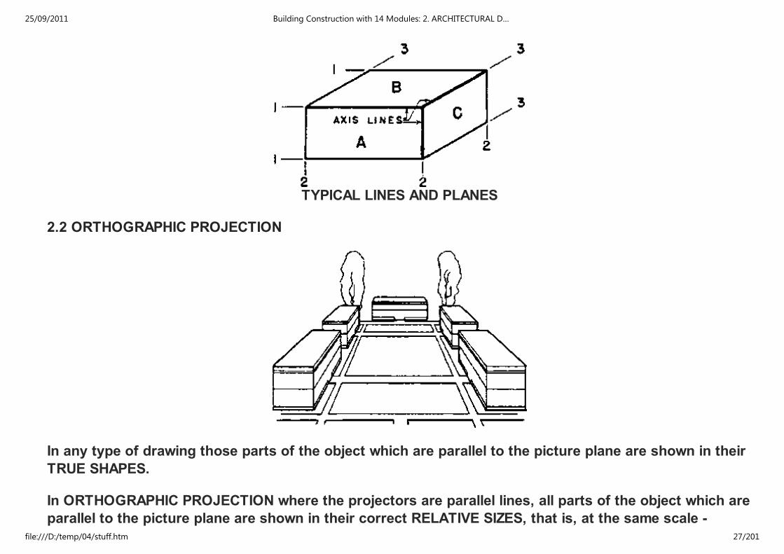
TYPICAL LINES AND PLANES
2.2 ORTHOGRAPHIC PROJECTION
In any type of drawing those parts of the object which are parallel to the picture plane are shown in their
TRUE SHAPES.
In ORTHOGRAPHIC PROJECTION where the projectors are parallel lines, all parts of the object which are
parallel to the picture plane are shown in their correct RELATIVE SIZES, that is, at the same scale -
regardless of their distances from the picture plane.
25/09/2011 Building Construction with 14 Modules: 2. ARCHITECTURAL D…
file:///D:/temp/04/stuff.htm 27/201

regardless of their distances from the picture plane.
Since only one set of planes of an object can be shown parallel to the picture plane in a single drawing, it
is necessary to have a minimum number of three views of an object to give all of its sizes and shapes.
These three basic views are obtained by looking in three mutually perpendicular directions, and these
views are drawn on planes perpendicular to each of the three directions respectively.
The basic views, which are drawn true to scale, are taken at 90° to each other and when set on paper are
said to be drawn in the principal planes.
At present there are two methods of relating the principal views to each other, namely FIRST-ANGLE
PROJECTION (used in Europe) and THIRD ANGLE PROJECTION (used in Canada and U.S.A.)
These terms FIRST ANGLE and THIRD ANGLE have been derived from the mathematicians convention of
annotating the four right angles which make up the 360° of a circle, the first being 0° to 90° and the third
angle from 180° to 270°.
25/09/2011 Building Construction with 14 Modules: 2. ARCHITECTURAL D…
file:///D:/temp/04/stuff.htm 28/201

1st ANGLE PROJECTION
1. Projection of a Point (A)
25/09/2011 Building Construction with 14 Modules: 2. ARCHITECTURAL D…
file:///D:/temp/04/stuff.htm 29/201

Orthographic projection of point A
25/09/2011 Building Construction with 14 Modules: 2. ARCHITECTURAL D…
file:///D:/temp/04/stuff.htm 30/201

2. Projection of a line (AB)
(a) AB ⊥⊥⊥⊥ VP
25/09/2011 Building Construction with 14 Modules: 2. ARCHITECTURAL D…
file:///D:/temp/04/stuff.htm 31/201

25/09/2011 Building Construction with 14 Modules: 2. ARCHITECTURAL D…
file:///D:/temp/04/stuff.htm 32/201

(b) AB NOT parallel to any plane
25/09/2011 Building Construction with 14 Modules: 2. ARCHITECTURAL D…
file:///D:/temp/04/stuff.htm 33/201

25/09/2011 Building Construction with 14 Modules: 2. ARCHITECTURAL D…
file:///D:/temp/04/stuff.htm 34/201

25/09/2011 Building Construction with 14 Modules: 2. ARCHITECTURAL D…
file:///D:/temp/04/stuff.htm 35/201

(A) PROJECTING ONTO THE GLASS BOX
(B) REVOLVING PLANES OF THE GLASS BOX
25/09/2011 Building Construction with 14 Modules: 2. ARCHITECTURAL D…
file:///D:/temp/04/stuff.htm 36/201

(C) ARRANGEMENT OF DRAWINGS FROM THE GLASS BOX
(D) ARCHITECTURAL ARRANGEMENTS
25/09/2011 Building Construction with 14 Modules: 2. ARCHITECTURAL D…
file:///D:/temp/04/stuff.htm 37/201

(E) ARCHITECTURAL ARRANGEMENTS
The planes provided by the transparent box - shape of the figure are not always adequate to give TRUE
SHAPE VIEWS of all sides of a building. If a wall of the building is not parallel one of the typical planes
and consequently one of the faces of the transparent box, its TRUE SHAPE will not be shown by any of
the conventional elevations. Picture planes, which are added to the transparent box - shape in order to
obtain true shape views of planes of the object not parallel to the original planes of the box, are called
AUXILIARY PLANES (see figure A and D) and the projections made on these planes are called AUXILIARY
VIEWS.
The true shape of any oblique surface, such as a slating roof or wall, can then be obtained by projecting
onto an auxiliary plane parallel to the oblique surface.
AUXILIARY VIEWS
ELEVATION AUXILIARIES
25/09/2011 Building Construction with 14 Modules: 2. ARCHITECTURAL D…
file:///D:/temp/04/stuff.htm 38/201

(A) VERTICAL AUXILIARY PLANE
(B) COMPLETE AUXILIARY VIEW
25/09/2011 Building Construction with 14 Modules: 2. ARCHITECTURAL D…
file:///D:/temp/04/stuff.htm 39/201

(C) PART AUXILIARY VIEW
OBLIQUE PLANE AUXILIARIES
(D) OBLIQUE AUXILIARY PLANE
25/09/2011 Building Construction with 14 Modules: 2. ARCHITECTURAL D…
file:///D:/temp/04/stuff.htm 40/201

(E) GABLE ROOF AUXILIARY
25/09/2011 Building Construction with 14 Modules: 2. ARCHITECTURAL D…
file:///D:/temp/04/stuff.htm 41/201

(F) HIP ROOF AUXILIARY
2.2.1 CONSTRUCTION OF ORTHOGRAPHIC PROJECTION
In the CONSTRUCTION of orthographic projections, it should be kept in mind that all the different views
must check. Drafting methods for the construction of orthographic projections are shown in the figure.
EQUAL DIVISIONS ON GEOMETRIC SHAPES
(A) TURNING MEASUREMENTS WITH CIRCULAR ARCS
25/09/2011 Building Construction with 14 Modules: 2. ARCHITECTURAL D…
file:///D:/temp/04/stuff.htm 42/201

(B) TURNING MEASUREMENTS ON A 45° BISECTOR
(C) OCTAGON
(D) CONE
25/09/2011 Building Construction with 14 Modules: 2. ARCHITECTURAL D…
file:///D:/temp/04/stuff.htm 43/201

(D) CONE
(E) CYLINDER
25/09/2011 Building Construction with 14 Modules: 2. ARCHITECTURAL D…
file:///D:/temp/04/stuff.htm 44/201

(F) OCTAGONAL BUILDING
25/09/2011 Building Construction with 14 Modules: 2. ARCHITECTURAL D…
file:///D:/temp/04/stuff.htm 45/201

(G) SPIRAL STAIRS
2.2.2 ELEVATIONS
The most common auxiliary views in architecture are ELEVATIONS. The drafting process by which an
auxiliary elevation is made may vary in details of construction. However, in all cases the heights may be
taken from any other elevation of the building and the horizontal dimensions from plan.
The figure shows two methods of making the auxiliary elevation from a front elevation and plan. In B the
auxiliary drawing is made to show the entire building, as would usually be done in architectural drawing.
In C only the part of the building parallel to the picture plane is shown in each elevation.
25/09/2011 Building Construction with 14 Modules: 2. ARCHITECTURAL D…
file:///D:/temp/04/stuff.htm 46/201

In C only the part of the building parallel to the picture plane is shown in each elevation.
The front roof plane of E is shown by the front elevation to be a rectangle. The length of this roof area is
shown in the front view and its true slant-height is shown in the side view. The rectangle made by using
these two dimensions is the correct auxiliary view of the front roof plane.
In F all four planes of the simple hip roof are drawn in the auxiliary views. Such drawings are useful to
show the true shapes and areas of the roof planes and the true lengths of lines in those planes. The
slanting lines in the auxiliary view of F show the true length of the hips. The length of any straight line
can be determined graphically by making an auxiliary view on any picture plane parallel to the line.
(A) POSITION OF PLANE
(B) TOP PART REMOVED
25/09/2011 Building Construction with 14 Modules: 2. ARCHITECTURAL D…
file:///D:/temp/04/stuff.htm 47/201

(B) TOP PART REMOVED
(C) PLAN OF REMAINDER
(D) ROOF PLAN
25/09/2011 Building Construction with 14 Modules: 2. ARCHITECTURAL D…
file:///D:/temp/04/stuff.htm 48/201

(E) FRAMING PLAN
(F) REFLECTED PLAN
2.2.3 PLANS AND SECTIONS
In addition to the exterior views of building it is usually necessary to have one or more views made which
CUT through the structure and shows the interior. These views are known as
1. PLAN, which is the term applied to any view on a HORIZONTAL PICTURE PLANE either from
the exterior or cut through, and
2. SECTION, which is the name given to any view cutting through the building on a VERTICAL
PLANE.
Both, the ARCHITECTURAL PLAN as well as the ARCHITECTURAL SECTION are demonstrated in the
figure.
25/09/2011 Building Construction with 14 Modules: 2. ARCHITECTURAL D…
file:///D:/temp/04/stuff.htm 49/201

(A) POSITION OF PLANE
(B) RIGHT SIDE REMOVED
25/09/2011 Building Construction with 14 Modules: 2. ARCHITECTURAL D…
file:///D:/temp/04/stuff.htm 50/201

(C) SECTION OF REMAINDER
(D) TRANSVERSE SECTION
25/09/2011 Building Construction with 14 Modules: 2. ARCHITECTURAL D…
file:///D:/temp/04/stuff.htm 51/201
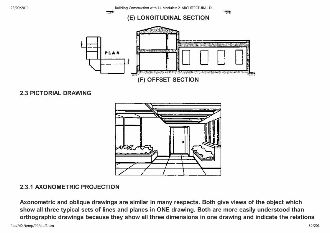
(E) LONGITUDINAL SECTION
(F) OFFSET SECTION
2.3 PICTORIAL DRAWING
2.3.1 AXONOMETRIC PROJECTION
Axonometric and oblique drawings are similar in many respects. Both give views of the object which
show all three typical sets of lines and planes in ONE drawing. Both are more easily understood than
orthographic drawings because they show all three dimensions in one drawing and indicate the relations
of the various parts of the object to each other.
25/09/2011 Building Construction with 14 Modules: 2. ARCHITECTURAL D…
file:///D:/temp/04/stuff.htm 52/201
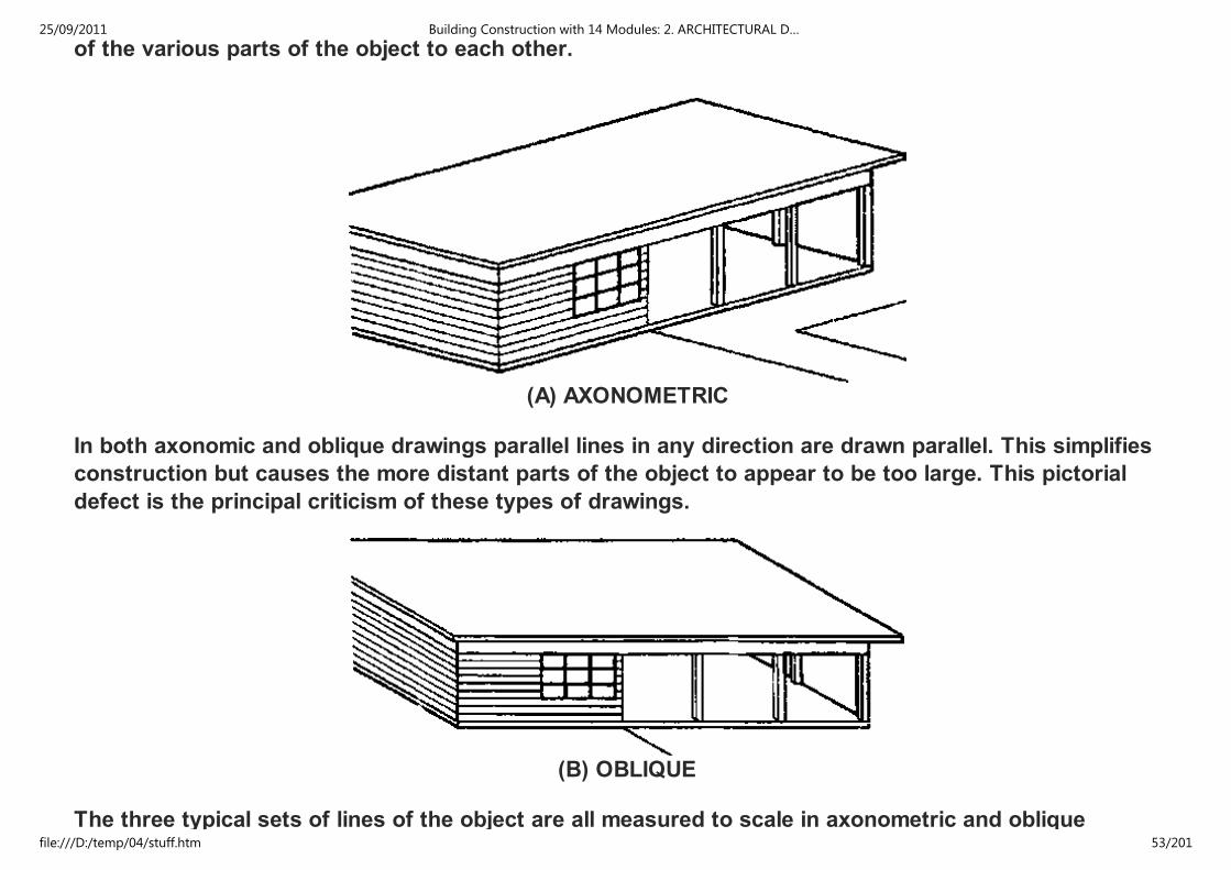
of the various parts of the object to each other.
(A) AXONOMETRIC
In both axonomic and oblique drawings parallel lines in any direction are drawn parallel. This simplifies
construction but causes the more distant parts of the object to appear to be too large. This pictorial
defect is the principal criticism of these types of drawings.
(B) OBLIQUE
The three typical sets of lines of the object are all measured to scale in axonometric and oblique
25/09/2011 Building Construction with 14 Modules: 2. ARCHITECTURAL D…
file:///D:/temp/04/stuff.htm 53/201
The three typical sets of lines of the object are all measured to scale in axonometric and oblique
drawings. Therefore, most of the measuring can usually be done directly on the lines of the drawing
itself, and it is practical to give dimensions on the drawings. Simplicity of construction is the chief
advantage of these drawings over perspective drawing.
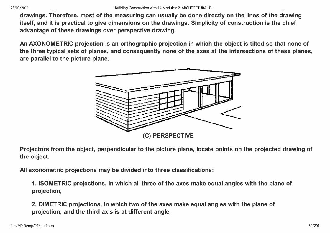
An AXONOMETRIC projection is an orthographic projection in which the object is tilted so that none of
the three typical sets of planes, and consequently none of the axes at the intersections of these planes,
are parallel to the picture plane.
(C) PERSPECTIVE
Projectors from the object, perpendicular to the picture plane, locate points on the projected drawing of
the object.
All axonometric projections may be divided into three classifications:
1. ISOMETRIC projections, in which all three of the axes make equal angles with the plane of
projection,
2. DIMETRIC projections, in which two of the axes make equal angles with the plane of
projection, and the third axis is at different angle,
3. TRIMETRIC projections, in which all three axes are at different angles with the picture plane.
25/09/2011 Building Construction with 14 Modules: 2. ARCHITECTURAL D…
file:///D:/temp/04/stuff.htm 54/201
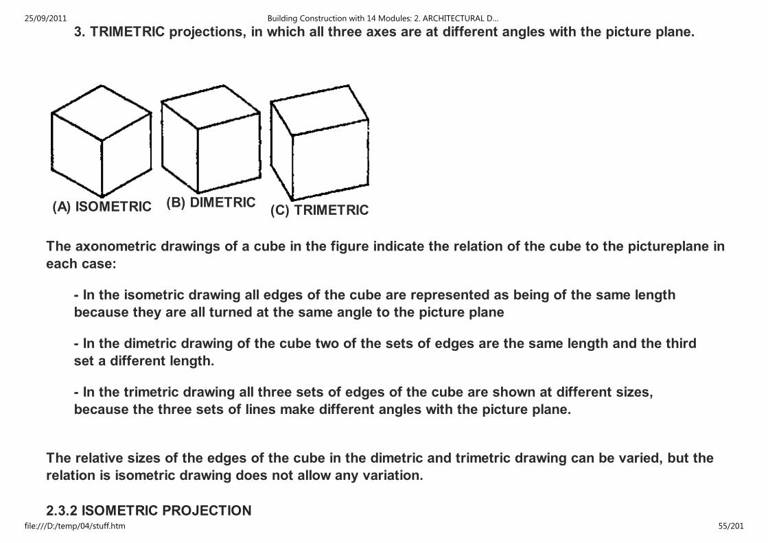
3. TRIMETRIC projections, in which all three axes are at different angles with the picture plane.
(A) ISOMETRIC (B) DIMETRIC(C) TRIMETRIC
The axonometric drawings of a cube in the figure indicate the relation of the cube to the pictureplane in
each case:
- In the isometric drawing all edges of the cube are represented as being of the same length
because they are all turned at the same angle to the picture plane
- In the dimetric drawing of the cube two of the sets of edges are the same length and the third
set a different length.
- In the trimetric drawing all three sets of edges of the cube are shown at different sizes,
because the three sets of lines make different angles with the picture plane.
The relative sizes of the edges of the cube in the dimetric and trimetric drawing can be varied, but the
relation is isometric drawing does not allow any variation.
2.3.2 ISOMETRIC PROJECTION
25/09/2011 Building Construction with 14 Modules: 2. ARCHITECTURAL D…
file:///D:/temp/04/stuff.htm 55/201

2.3.2 ISOMETRIC PROJECTION
A scale is assumed for the object and the projected or foreshortened size drawing for that scale is
shown in an isometric projection. The projected size of the axis lines is 0.816 of the actual length of the
lines. An isometric drawing of an object is measured at any desired scale without considering the scale
size of the object represented. The figure shows the difference in size between the isometric projection
(B) made with the isometric scale and the isometric drawing (C) measured with the ordinary scale.
Although isometric drawings are satisfactory for most practical purposes isometric projections
sometimes have advantages.
(A) ISOMETRIC AXES
(B) ISOMETRIC PROJECTION
25/09/2011 Building Construction with 14 Modules: 2. ARCHITECTURAL D…
file:///D:/temp/04/stuff.htm 56/201

(C) ISOMETRIC DRAWING
Making an isometric drawing the angle between two adjacent axes of an isometric drawing is 120°. When
one axis is vertical the other two are at 30 with the horizontal. To make an isometric drawing of a simple
rectangular object: from a point selected for one of the front corners of the object draw the three axis
lines and lay out on these lines their scale sizes. From the ends of the lines draw lines parallel to the
axes to complete the drawing.
(A) MULTI-VIEW DRAWINGS
25/09/2011 Building Construction with 14 Modules: 2. ARCHITECTURAL D…
file:///D:/temp/04/stuff.htm 57/201

(B) AXES LOCATED
(C) OBJECT DRAWN
(A) ONE AXIS VERTICAL (B)
25/09/2011 Building Construction with 14 Modules: 2. ARCHITECTURAL D…
file:///D:/temp/04/stuff.htm 58/201
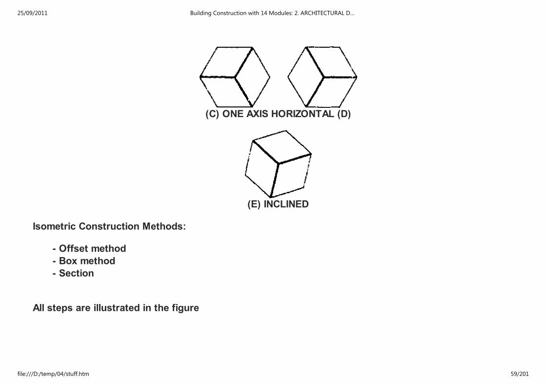
(C) ONE AXIS HORIZONTAL (D)
(E) INCLINED
Isometric Construction Methods:
- Offset method
- Box method
- Section
All steps are illustrated in the figure
25/09/2011 Building Construction with 14 Modules: 2. ARCHITECTURAL D…
file:///D:/temp/04/stuff.htm 59/201
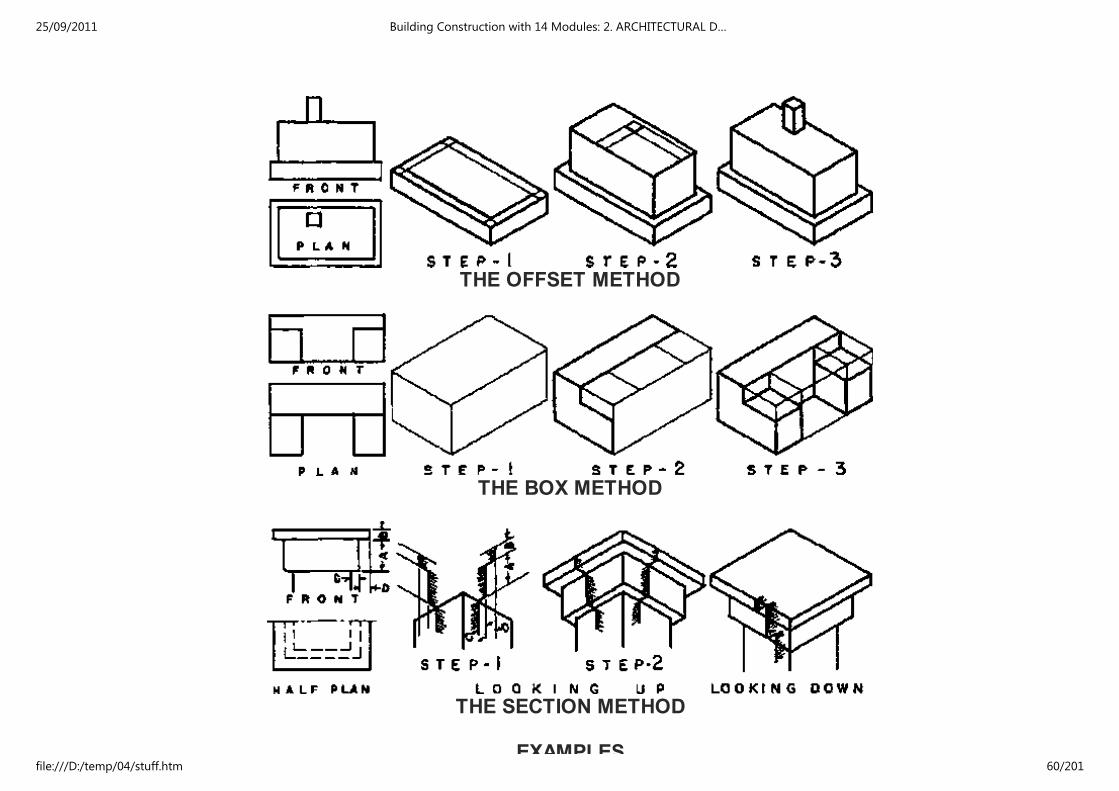
THE OFFSET METHOD
THE BOX METHOD
THE SECTION METHOD
EXAMPLES
25/09/2011 Building Construction with 14 Modules: 2. ARCHITECTURAL D…
file:///D:/temp/04/stuff.htm 60/201

EXAMPLES
(A) EXTERIOR OF BUILDING
25/09/2011 Building Construction with 14 Modules: 2. ARCHITECTURAL D…
file:///D:/temp/04/stuff.htm 61/201
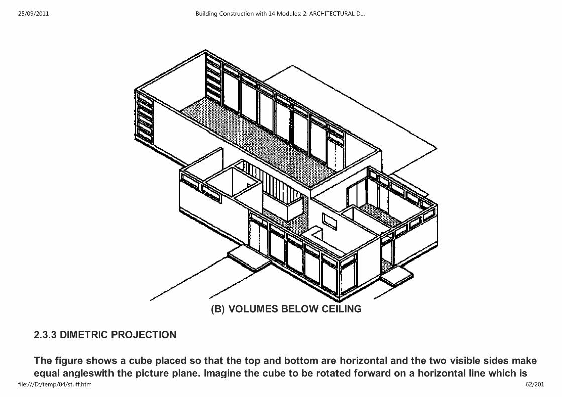
(B) VOLUMES BELOW CEILING
2.3.3 DIMETRIC PROJECTION
The figure shows a cube placed so that the top and bottom are horizontal and the two visible sides make
equal angleswith the picture plane. Imagine the cube to be rotated forward on a horizontal line which is
25/09/2011 Building Construction with 14 Modules: 2. ARCHITECTURAL D…
file:///D:/temp/04/stuff.htm 62/201

equal angleswith the picture plane. Imagine the cube to be rotated forward on a horizontal line which is
parallel to the picture plane, thus keeping the sides allways at equal angles to the picture plane until the
top is in a vertical position.
As the cube was rotated between these two positions the projections of its axes passed through all
possible dimetric relations to each other. A few of the infinite number of possible dimetric positions
obtained in this manner are illustrated in the figure. In these illustrations the two equal axes are turned
to make equal angles with a horizontal line. If one of these equal axes is turned vertically then the axes
to either side will be at different scales and at different angles with a horizontal line. Thus it is possible
to use the same spacings of the axes that are shown in the left column of the figure and twist them to
new positions with one of the two equal axes in a vertical position and get a new set of pictorial effects,
such as are illustrated in the right column of the figure. Dimetric drawings can then be made with the
angles and scales giving either a symmetrical or an unsymmetrical arrangement.
1
I
2
II
25/09/2011 Building Construction with 14 Modules: 2. ARCHITECTURAL D…
file:///D:/temp/04/stuff.htm 63/201

3III
4 IV
5
V
VI
25/09/2011 Building Construction with 14 Modules: 2. ARCHITECTURAL D…
file:///D:/temp/04/stuff.htm 64/201

6
VI
SYMMETRICAL UNSYMMETRICAL
Isometric drawing is rigid and inflexible. There is only one possible view of the three typical planes which
meet in any corner of the object because the axes must be equally spaced.
Because of its great variety of possible pictorial effects dimetric drawing overcomes the following faults
and shortcomings of isometric drawings:
1) The lines of a hip roof and of equal projections of the near corner form parts of continuous
vertical line in isometric drawing. This pictorial defect can be avoided in dimetric drawing by
using the position of axes, which causes the two sides of the object to be turned at different
angles to the picture plane.
2) One of the three typical planes of the object can be emphasized in dimetric drawing by
turning the object so that this plane is seen more directly and consequently occupies a greater
proportionate area in the drawing. The emphasis on one plane and subordination of the other
two can be in any desired ratio.
3) Two of the planes of the object can be emphasized equally and the third subordinated. Thus,
it is possible to subordinate the roof or floor area and emphasize the walls or to subordinate one
wall. An example of subordination of roof areas and relatively increased importance of wall areas
are shown in the figure. By showing less of the roof it is also possible to see more of the wall
under an extending roof.
4) The unpleasant effect of wall planes at 45° in isometric projection can be avoided in dimetric
drawing.
25/09/2011 Building Construction with 14 Modules: 2. ARCHITECTURAL D…
file:///D:/temp/04/stuff.htm 65/201

Dimetric drawing has the advantage of allowing the choice of a symmetrical or unsymmetrical view of the
object and emphasis on one or two of the three planes. It permits variation in the pictorial effect
obtained, while isometric drawing is rigid and inflexible.
A carefully chosen dimetric drawing usually gives the most pleasing results of any of the usable types of
parallel line pictorial drawing. It ranks next to perspective in desirability for presentation work.
(A) NATURAL APPEARANCE OF CORNERS AND ROOF LINES
(B) EMPHASIS ON IMPORTANT WALL FLOOR AND ONE WALL SUBORDINATED
25/09/2011 Building Construction with 14 Modules: 2. ARCHITECTURAL D…
file:///D:/temp/04/stuff.htm 66/201

(C) EMPHASIS ON TWO WALLS ROOF AREA SUBORDINATED
(D) CLEARER REPRESENTATION OF 45° WALL SURFACES
ISOMETRIC DIMETRIC
DIMETRIC SCALES &. ANGLES
25/09/2011 Building Construction with 14 Modules: 2. ARCHITECTURAL D…
file:///D:/temp/04/stuff.htm 67/201
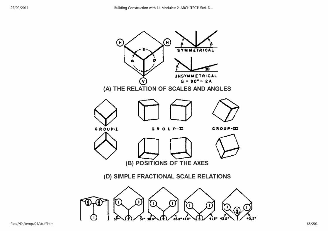
(A) THE RELATION OF SCALES AND ANGLES
(B) POSITIONS OF THE AXES
(D) SIMPLE FRACTIONAL SCALE RELATIONS
25/09/2011 Building Construction with 14 Modules: 2. ARCHITECTURAL D…
file:///D:/temp/04/stuff.htm 68/201

SYMMETRICAL
UNSYMMETRICAL
MAKING A DIMETRIC DRAWING
(A)
(B)
25/09/2011 Building Construction with 14 Modules: 2. ARCHITECTURAL D…
file:///D:/temp/04/stuff.htm 69/201

(B)
(C)
(D)
25/09/2011 Building Construction with 14 Modules: 2. ARCHITECTURAL D…
file:///D:/temp/04/stuff.htm 70/201

(E)
EXAMPLES
(A) A VILLAGE CHURCH
(B) A BOATHOUSE
2.3.4 OBLIQUE PROJECTION
25/09/2011 Building Construction with 14 Modules: 2. ARCHITECTURAL D…
file:///D:/temp/04/stuff.htm 71/201

In oblique projection the projectors are oblique to the picture plane and the object is usually turned with
one of the typical planes parallel to the picture plan (see fig. A)
In axonometric projection the projectors are perpendicular to the picture plane and the object has all
three typical planes oblique to the picture plane. Thus, both the relation of the object to the picture plane
and the direction of the projectors in oblique drawing differ from those of axonometric drawing.
(A) PICTORIAL VIEW OF OBJECT AND DRAWINGS
Although the drawings M and O of figure A may be considered oblique drawings they are made with the
projectors in planes parallel to one of the typical planes of the object and are neither good pictorial
drawings nor characteristic oblique drawings. Drawing N shows the characteristic oblique drawing in
which the projectors are oblique to the three typical planes of the object. Fig. B shows these drawings as
they would appear from in front of the picture plane.
25/09/2011 Building Construction with 14 Modules: 2. ARCHITECTURAL D…
file:///D:/temp/04/stuff.htm 72/201
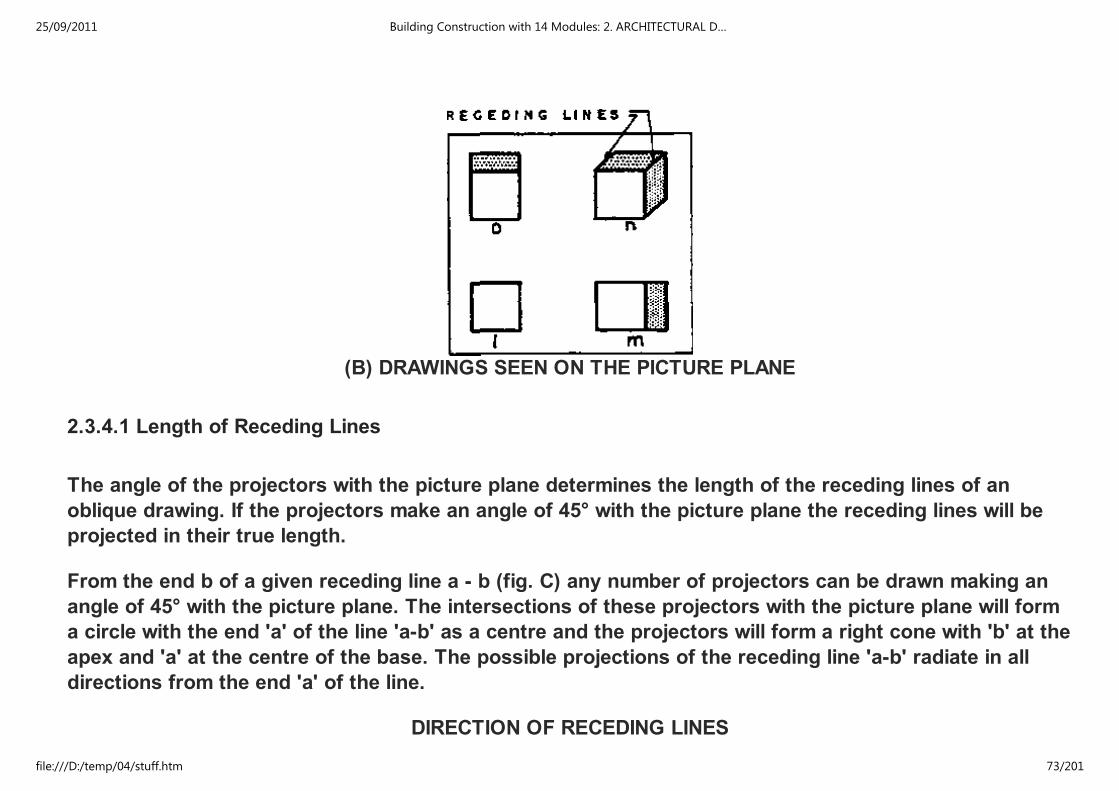
(B) DRAWINGS SEEN ON THE PICTURE PLANE
2.3.4.1 Length of Receding Lines
The angle of the projectors with the picture plane determines the length of the receding lines of an
oblique drawing. If the projectors make an angle of 45° with the picture plane the receding lines will be
projected in their true length.
From the end b of a given receding line a - b (fig. C) any number of projectors can be drawn making an
angle of 45° with the picture plane. The intersections of these projectors with the picture plane will form
a circle with the end 'a' of the line 'a-b' as a centre and the projectors will form a right cone with 'b' at the
apex and 'a' at the centre of the base. The possible projections of the receding line 'a-b' radiate in all
directions from the end 'a' of the line.
DIRECTION OF RECEDING LINES
25/09/2011 Building Construction with 14 Modules: 2. ARCHITECTURAL D…
file:///D:/temp/04/stuff.htm 73/201
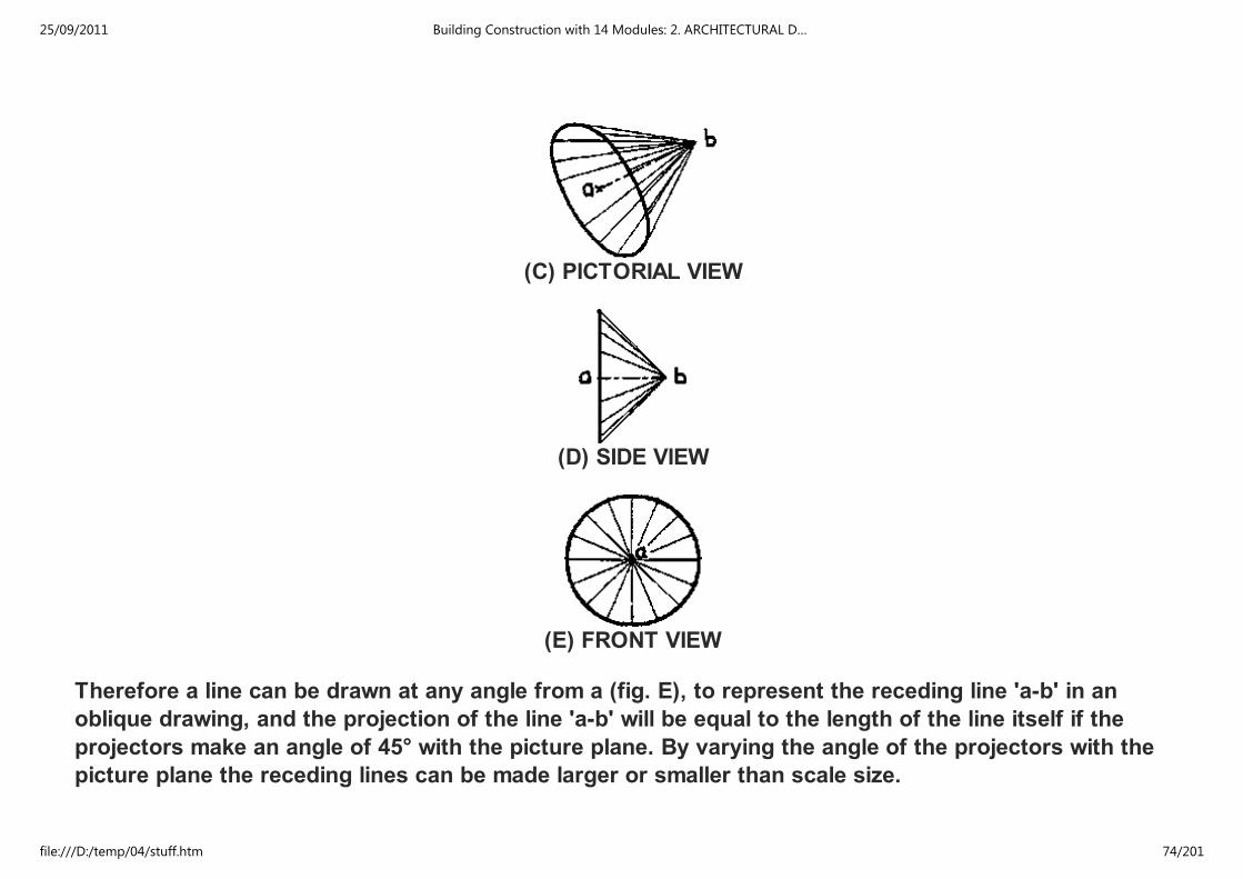
(C) PICTORIAL VIEW
(D) SIDE VIEW
(E) FRONT VIEW
Therefore a line can be drawn at any angle from a (fig. E), to represent the receding line 'a-b' in an
oblique drawing, and the projection of the line 'a-b' will be equal to the length of the line itself if the
projectors make an angle of 45° with the picture plane. By varying the angle of the projectors with the
picture plane the receding lines can be made larger or smaller than scale size.
25/09/2011 Building Construction with 14 Modules: 2. ARCHITECTURAL D…
file:///D:/temp/04/stuff.htm 74/201

2.3.4.2 Construction of Oblique Drawings
The block shape shown in fig. A is drawn in oblique by proceeding as follows:
Step 1: Draw the horizontal and vertical axes and from their intersection lay out the receding
axis at any desire angle.
Step 2: Lay out the dimensions of the object on the axis lines
25/09/2011 Building Construction with 14 Modules: 2. ARCHITECTURAL D…
file:///D:/temp/04/stuff.htm 75/201

Step 3: Draw lines from the measurements to complete the drawing.
Offset Method: The way of construction is illustrated in fig. B. Usually most measurements on an oblique
drawing can be made on lines parallel to the axes. However, the planes of the object which are parallel to
the picture plane appear in their true shapes and measurements can be made on them at any angle.
Furthermore, any slanting lines which are parallel to the picture plane are drawn in their true directions
and lengths.
(B) OFFSET CONSTRUCTION
2.3.4.3 Rules of Oblique Drawing
There are two rules of oblique drawing which should be followed when it is practical to do so (see fig. C)
Rule 1: Turn the length of the object parallel to the picture plane
Rule 2: Turn the most complex or characteristic face of the object parallel to the picture plane
25/09/2011 Building Construction with 14 Modules: 2. ARCHITECTURAL D…
file:///D:/temp/04/stuff.htm 76/201

(C) SELECTING THE VIEW
The purpose of the first rule is to decrease the appearance of distortion by making the reciding lines
represent the short dimension of the object.
The purpose of the second rule is to show the true shapes of characteristic forms of the object and
simplify construction.
2.3.4.4 Scale of the Receding Lines
Since the projectors can be at any angle with the picture plane the receding lines of an oblique drawing
can be drawn at any scale.
The four drawings of the cube in the figure show the effect of different scales for the receding lines on
the proportions of the drawings.
25/09/2011 Building Construction with 14 Modules: 2. ARCHITECTURAL D…
file:///D:/temp/04/stuff.htm 77/201
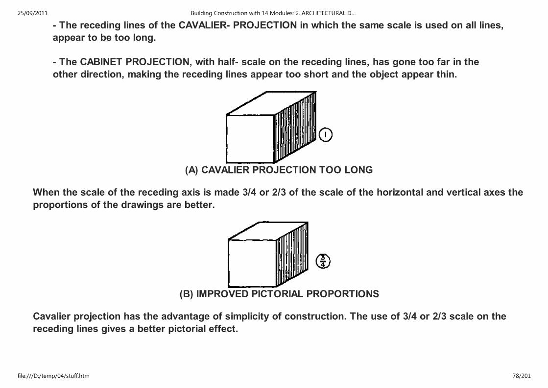
- The receding lines of the CAVALIER- PROJECTION in which the same scale is used on all lines,
appear to be too long.
- The CABINET PROJECTION, with half- scale on the receding lines, has gone too far in the
other direction, making the receding lines appear too short and the object appear thin.
(A) CAVALIER PROJECTION TOO LONG
When the scale of the receding axis is made 3/4 or 2/3 of the scale of the horizontal and vertical axes the
proportions of the drawings are better.
(B) IMPROVED PICTORIAL PROPORTIONS
Cavalier projection has the advantage of simplicity of construction. The use of 3/4 or 2/3 scale on the
receding lines gives a better pictorial effect.
25/09/2011 Building Construction with 14 Modules: 2. ARCHITECTURAL D…
file:///D:/temp/04/stuff.htm 78/201

(C) IMPROVED PICTORIAL PROPORTIONS
One of these scales should be used when appearance is an important factor.
(D) CABINET PROJECTION TOO SHORT
2.3.4.5 Direction of Receding Lines
Since the receding axis of an oblique drawing can be drawn in any direction it is possible to secure a
great variety of pictorial effects. The figure shows three variations of direction of the receding lines for
an exterior and an interior.
25/09/2011 Building Construction with 14 Modules: 2. ARCHITECTURAL D…
file:///D:/temp/04/stuff.htm 79/201

2.3.4.6 Position of Axes
In all the preceding illustrations of oblique drawing one axis has been horizontal and another vertical.
However, the axes may be turned in any position, if two of the three are kept at 90° with each other.
In A: One axis is vertical, another horizontal
In B: The oblique axis is horizontal
In C: None of the axes is vertical or horizontal
In D: The oblique axis is vertical
25/09/2011 Building Construction with 14 Modules: 2. ARCHITECTURAL D…
file:///D:/temp/04/stuff.htm 80/201

(A) ELEVATION PLANE TRUE SHAPE ELEVATION OBLIQUE
(B) END TRUE SHAPE RECEDING LINES HORIZONTAL
(C) INCLINED OBJECT ALL OF AXES OBLIQUE LINES
(D) PLAN PLANE TRUE SHAPE PLAN OBLIQUE
The PLAN OBLIQUE axis position, shown in D, is often used in drawing pictorial views in which it is
advantageous to have the picture plane horizontal and parallel to the floor plane. This position of the
axis allows all horizontal areas to appear in their true forms.
For either interior or exterior designs having horizontal, circular or other complex forms this
25/09/2011 Building Construction with 14 Modules: 2. ARCHITECTURAL D…
file:///D:/temp/04/stuff.htm 81/201

For either interior or exterior designs having horizontal, circular or other complex forms this
arrangement of the axes is to be recommended for simplicity of construction and for clearest
representation of the shapes. With the oblique axis vertical, the other axes must remain at 90° with each
other but may be turned in any desired relation to the vertical axis. The oblique lines (vertical) should be
drawn at 2/3 or 3/4 scale.
TRUE SHAPE PLANES ARE SHADED ON THIS PAGE
SCALE AND ANGLE DIAGRAM
25/09/2011 Building Construction with 14 Modules: 2. ARCHITECTURAL D…
file:///D:/temp/04/stuff.htm 82/201

(A) ALL WALLS SHOWN
25/09/2011 Building Construction with 14 Modules: 2. ARCHITECTURAL D…
file:///D:/temp/04/stuff.htm 83/201
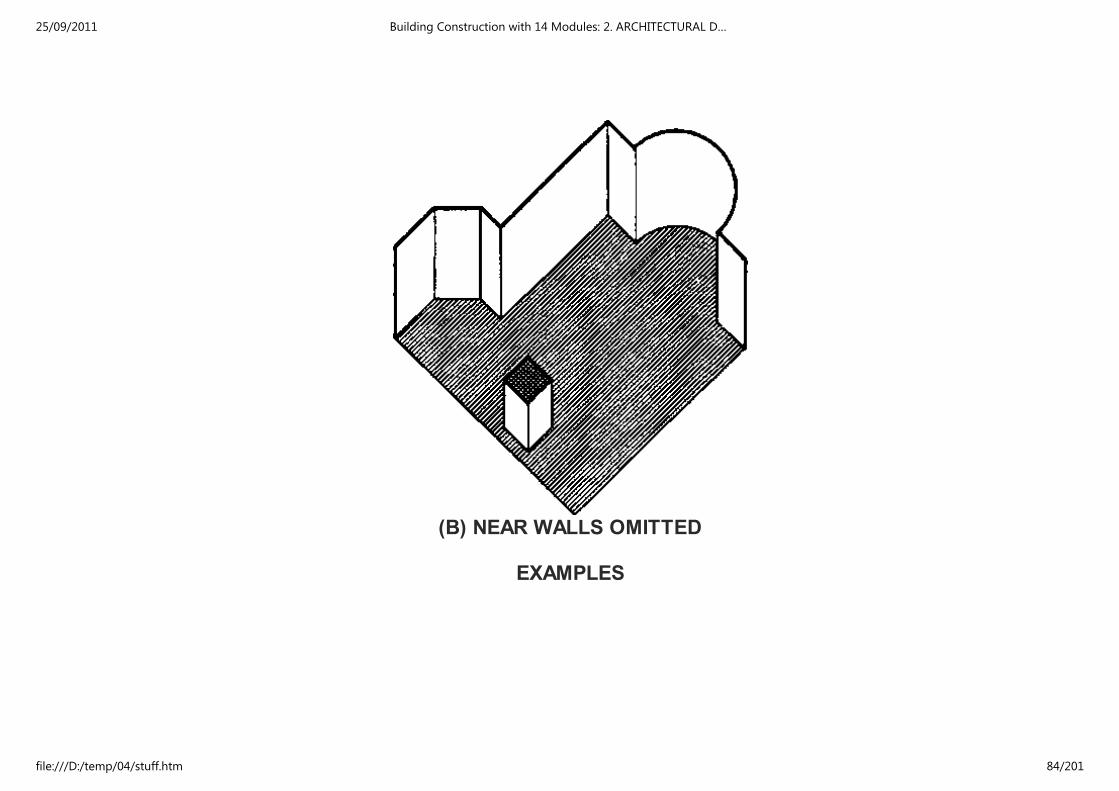
(B) NEAR WALLS OMITTED
EXAMPLES
25/09/2011 Building Construction with 14 Modules: 2. ARCHITECTURAL D…
file:///D:/temp/04/stuff.htm 84/201
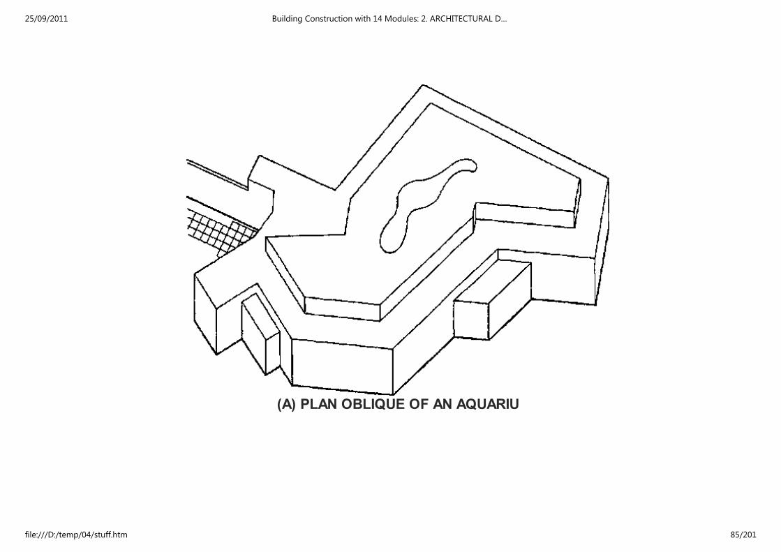
(A) PLAN OBLIQUE OF AN AQUARIU
25/09/2011 Building Construction with 14 Modules: 2. ARCHITECTURAL D…
file:///D:/temp/04/stuff.htm 85/201

(B) ELEVATION OBLIQUE OF A RESTAURANT
2.4 PERSPECTIVE DRAWING
Perspective drawing is essential in the work of the architect and designer, because it is the only type of
25/09/2011 Building Construction with 14 Modules: 2. ARCHITECTURAL D…
file:///D:/temp/04/stuff.htm 86/201
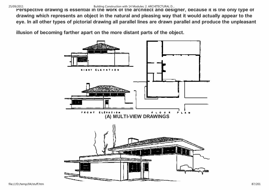
Perspective drawing is essential in the work of the architect and designer, because it is the only type of
drawing which represents an object in the natural and pleasing way that it would actually appear to the
eye. In all other types of pictorial drawing all parallel lines are drawn parallel and produce the unpleasant
illusion of becoming farther apart on the more distant parts of the object.
(A) MULTI-VIEW DRAWINGS
25/09/2011 Building Construction with 14 Modules: 2. ARCHITECTURAL D…
file:///D:/temp/04/stuff.htm 87/201

(B) PERSPECTIVE DRAWING
PERSPECTIVE is of value for:
1. drawings which can be easily understood by anyone,
2. an accurate method of studying and perfecting designs, and
3. explanatory sketches and drawings.
2.4.1 PERSPECTIVE TERMS
STAND POINT (S.P.) is the position of the observers eye and is assumed to be the position from which
an object is seen.
PROJECTORS. In perspective drawing the projectors converge to a station point instead of being
parallel as they are in all other types of drawings.
Perspective projectors are imaginary lines of sight from the eye of the observer to points on the object.
PICTURE PLANE (P.P.) is an imaginary plane which intersect the perspective projectors in order to give
points through which the perspective drawing is made, as though drawn on the picture plane.
VANISHING POINT (V.P.) is a point at which lines, not parallel to the P.P. appear to meet on the horizon
line.
CENTRE OF SIGHT is the point at which the line of sight meets the P.P. and should be as near as
possible to the centre of the object.
25/09/2011 Building Construction with 14 Modules: 2. ARCHITECTURAL D…
file:///D:/temp/04/stuff.htm 88/201
GROUND PLAN (G.P.) is the horizontal plane on which the object rests.
GROUND LINE (G.L.) is the intersection of the ground plane and the picture plane.
HORIZON LINE (H.L.) is the line parallel to the ground line and passing through the centre of sight on
EYE LEVEL (E.L.).
2.4.2 PHENOMENA OF PERSPECTIVE DRAWING
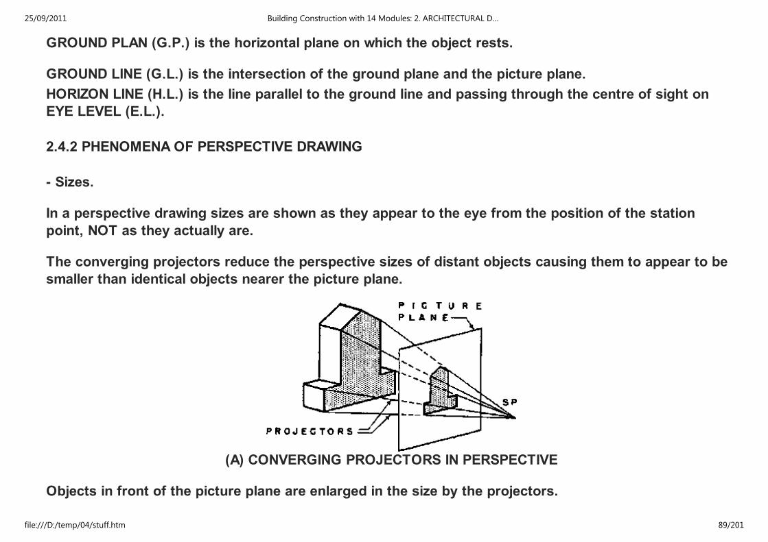
- Sizes.
In a perspective drawing sizes are shown as they appear to the eye from the position of the station
point, NOT as they actually are.
The converging projectors reduce the perspective sizes of distant objects causing them to appear to be
smaller than identical objects nearer the picture plane.
(A) CONVERGING PROJECTORS IN PERSPECTIVE
Objects in front of the picture plane are enlarged in the size by the projectors.
ONLY THE LINES IN THE PICTURE PLANE ARE DRAWN TO THEIR SCALE SIZES:
25/09/2011 Building Construction with 14 Modules: 2. ARCHITECTURAL D…
file:///D:/temp/04/stuff.htm 89/201

ONLY THE LINES IN THE PICTURE PLANE ARE DRAWN TO THEIR SCALE SIZES:
- Measurements.
Since lines of equal length on the object may appear in an infinite variety of sizes in a perspective
drawing, it is impossible to measure sizes directly on the drawing except in special cases. The
determination of sizes, and especially of heights, is one of the most difficult features of making an
perspective drawing.
Any lines of the object which lie in the picture plane can be measured to scale.
Parts of the object in front of the P.P. will be larger than scale size.
Parts of the object in the back of the P.P. will be smaller than scale size.
(B) PARALLEL PROJECTORS IN ALL OTHER DRAWING
The various methods of perspective drawing obtain this correction of sizes in different ways.
- Shapes.
In perspective drawing the object is represented as it appears to the eye. Areas and angles usually do
25/09/2011 Building Construction with 14 Modules: 2. ARCHITECTURAL D…
file:///D:/temp/04/stuff.htm 90/201

In perspective drawing the object is represented as it appears to the eye. Areas and angles usually do
not appear in perspective as they really are.
(C) EFFECT OF DISTANCE ON PERSPECTIVE
Rectangles and squares are often drawn as irregular quadrilaterals with four unequal sides and four
unequal angles.
A right angle seldom appears as such in a perspective but is drawn as an acute or obtuse angle. A circle
usually appears as an ellipse in perspective.
(D) VARIATIONS OF SIZE IN LINES AND AREAS
25/09/2011 Building Construction with 14 Modules: 2. ARCHITECTURAL D…
file:///D:/temp/04/stuff.htm 91/201
(D) VARIATIONS OF SIZE IN LINES AND AREAS
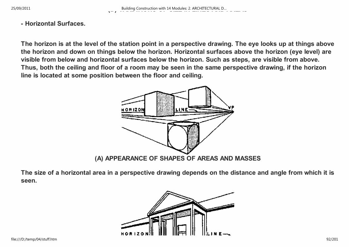
- Horizontal Surfaces.
The horizon is at the level of the station point in a perspective drawing. The eye looks up at things above
the horizon and down on things below the horizon. Horizontal surfaces above the horizon (eye level) are
visible from below and horizontal surfaces below the horizon. Such as steps, are visible from above.
Thus, both the ceiling and floor of a room may be seen in the same perspective drawing, if the horizon
line is located at some position between the floor and ceiling.
(A) APPEARANCE OF SHAPES OF AREAS AND MASSES
The size of a horizontal area in a perspective drawing depends on the distance and angle from which it is
seen.
25/09/2011 Building Construction with 14 Modules: 2. ARCHITECTURAL D…
file:///D:/temp/04/stuff.htm 92/201

(B) HORIZONTAL AREAS IN PERSPECTIVE
With the area at a constant horizontal distance from the station point, at the level of the horizon, a given
horizontal area appears as a line and increases in visible size with its distance above or below the
horizon.
When the height of a horizontal or vertical area is constant, its visible size increases as it approaches
the station point and diminishes as it recedes farther from the station point.
(C) EFFECT OF HEIGHT ON HORIZONTAL AREAS
Except that, whenever the line of vision passes through the plane of a surface the surface is always
seen as a LINE. I.e.: any horizontal plane at the level of the horizon would always appear as a straight
line.
- Lines Parallel to the Picture Plane.
These lines retain their true direction in perspective. Thus, horizontal and vertical lines parallel to the
25/09/2011 Building Construction with 14 Modules: 2. ARCHITECTURAL D…
file:///D:/temp/04/stuff.htm 93/201

picture plane remain respectively horizontal and vertical. Sets of parallel lines which are parallel to the
picture plane remain parallel perspective just as they do in orthographic projection.
However, the length of the parallel lines in perspective varies with the distance from the picture plane,
instead of being projected in actual size relations.
(D) EFFECT OF DISTANCE ON LINES AND AREAS
- Lines NOT Parallel to the Picture Plane.
In perspective each set of parallel lines which is not parallel to the picture plane converges to its
vanishing point. The vanishing points of all sets of horizontal lines are located on the horizon, which is
always on a level with the eye of the observer, the Station Point.
PERSPECTIVE SYSTEMS
PARALLEL OR ONE-POINT PERSPECTIVE SYSTEM
(A) PLAN
25/09/2011 Building Construction with 14 Modules: 2. ARCHITECTURAL D…
file:///D:/temp/04/stuff.htm 94/201

(B) PERSPECTIVE
ANGULAR OR TWO-POINT PERSPECTIVE SYSTEM
(C) PLAN
25/09/2011 Building Construction with 14 Modules: 2. ARCHITECTURAL D…
file:///D:/temp/04/stuff.htm 95/201

(D) PERSPECTIVE
OBLIQUE OR THREE-POINT PERSPECTIVE SYSTEM
(E) PLAN
25/09/2011 Building Construction with 14 Modules: 2. ARCHITECTURAL D…
file:///D:/temp/04/stuff.htm 96/201
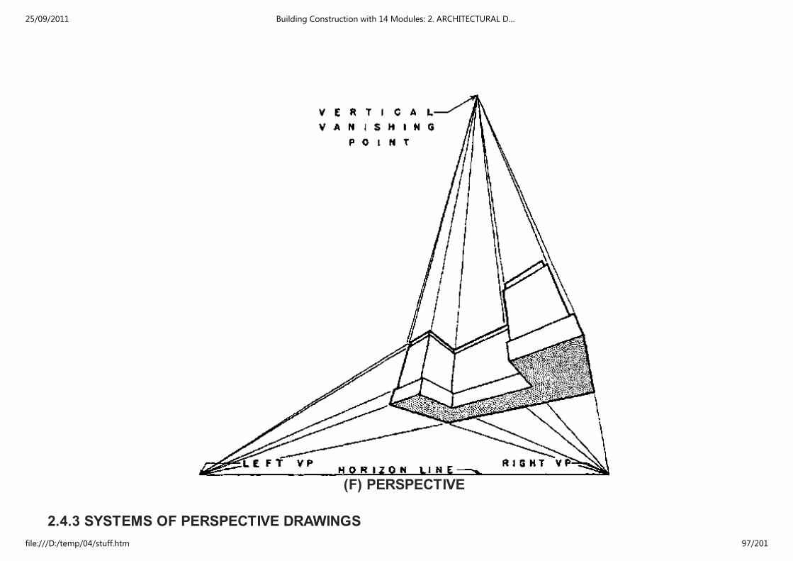
(F) PERSPECTIVE
2.4.3 SYSTEMS OF PERSPECTIVE DRAWINGS
25/09/2011 Building Construction with 14 Modules: 2. ARCHITECTURAL D…
file:///D:/temp/04/stuff.htm 97/201
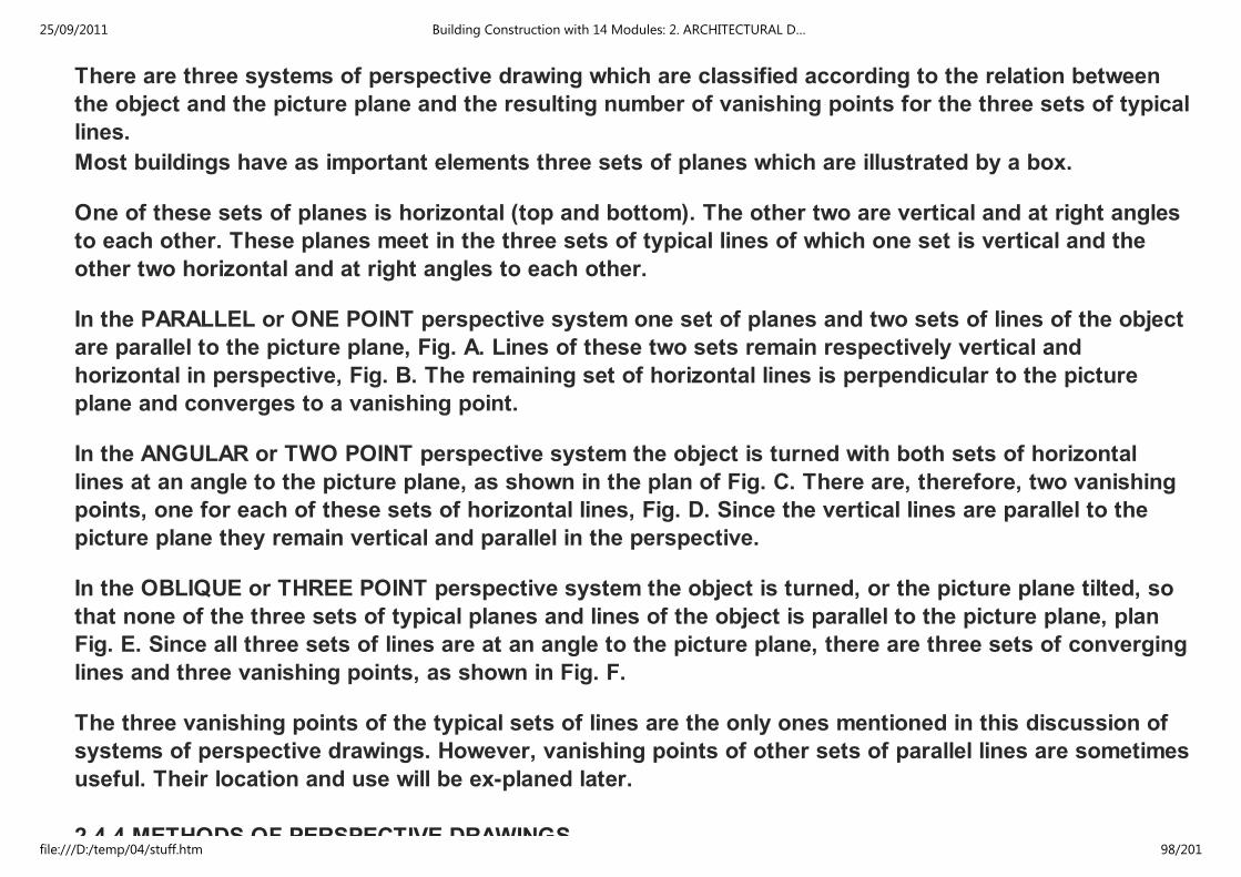
There are three systems of perspective drawing which are classified according to the relation between
the object and the picture plane and the resulting number of vanishing points for the three sets of typical
lines.
Most buildings have as important elements three sets of planes which are illustrated by a box.
One of these sets of planes is horizontal (top and bottom). The other two are vertical and at right angles
to each other. These planes meet in the three sets of typical lines of which one set is vertical and the
other two horizontal and at right angles to each other.
In the PARALLEL or ONE POINT perspective system one set of planes and two sets of lines of the object
are parallel to the picture plane, Fig. A. Lines of these two sets remain respectively vertical and
horizontal in perspective, Fig. B. The remaining set of horizontal lines is perpendicular to the picture
plane and converges to a vanishing point.
In the ANGULAR or TWO POINT perspective system the object is turned with both sets of horizontal
lines at an angle to the picture plane, as shown in the plan of Fig. C. There are, therefore, two vanishing
points, one for each of these sets of horizontal lines, Fig. D. Since the vertical lines are parallel to the
picture plane they remain vertical and parallel in the perspective.
In the OBLIQUE or THREE POINT perspective system the object is turned, or the picture plane tilted, so
that none of the three sets of typical planes and lines of the object is parallel to the picture plane, plan
Fig. E. Since all three sets of lines are at an angle to the picture plane, there are three sets of converging
lines and three vanishing points, as shown in Fig. F.
The three vanishing points of the typical sets of lines are the only ones mentioned in this discussion of
systems of perspective drawings. However, vanishing points of other sets of parallel lines are sometimes
useful. Their location and use will be ex-planed later.
2.4.4 METHODS OF PERSPECTIVE DRAWINGS
25/09/2011 Building Construction with 14 Modules: 2. ARCHITECTURAL D…
file:///D:/temp/04/stuff.htm 98/201
2.4.4 METHODS OF PERSPECTIVE DRAWINGS
A perspective of an existing object can be sketched on a picture plane made of a sheet of glass in the
following manner: Place the picture plane at arms length, keep the eye in one position, and draw lines to
exactly cover the lines of the object as seen through the stationary picture plane (see fig.). A window
glass makes an excellent picture plane for this purpose. Whenever the object is not conveniently
located, when greater accuracy is required, or when there is no existing object but only the drawings of
some proposed structure, it is necessary to use some other method of making the perspective.
However, the various drafting methods of making perspective drawings are based on this method of
sketching the perspective of an existing object on a transparent plane.
A perspective drawing is made by working out by one of the drafting methods the positions of the lines
of the object as they would appear on a given picture plane from a given station point. Three of these
mechanical methods of constructing perspective drawings:
1. the direct projection method
2. the perspective plan method
3. the common method.
These methods are described in a general way in the following paragraphs and are explained in detail in
the chapters on one- and two-point perspective.
THE DIRECT PROJECTION METHOD has the simplest theory of any method of perspective drawing. Plan
and elevation views parallel to the picture plane showing the object, picture plane, and station point are
first drawn the fig. The converging projectors are then traced to the picture plane in plan and elevation.
Points on the perspective drawing are located from their heights, which are determined from the
projectors in plan. The drawings are so arranged that the heights can be carried across horizontally with
the T-square and the widths brought down vertically with the triangle to their positions in the
perspective from the intersections of the projectors with the picture plane.
25/09/2011 Building Construction with 14 Modules: 2. ARCHITECTURAL D…
file:///D:/temp/04/stuff.htm 99/201

perspective from the intersections of the projectors with the picture plane.
SKETCHING A PERSPECTIVE
25/09/2011 Building Construction with 14 Modules: 2. ARCHITECTURAL D…
file:///D:/temp/04/stuff.htm 100/201

DIRECT PROJECTION METHOD
The direct projection method is a good method for one-point perspective because the auxiliary drawings
used are the plan and elevations, or sections. These drawings are easily understood by the draftsman,
and are often available at the correct scale. In two-point perspective one or two special drawings are
required for the direct projection method. These drawings are auxiliary elevations or sections from a
corner (parallel to the picture plane) and are more difficult to construct and understand than the ordinary
elevations and sections. If this method is used without vanishing points very, slight inaccuracies will
change the directions of short lines and produce a warped effect. This method requires a great deal of
space on the drafting board and many construction lines. Although vanishing points are not required
their use will simplify the construction and make the drawing more accurate.
THE PERSPECTIVE PLAN METHOD allows the entire perspective to be constructed from measurements
made in the picture plane and brought into correct perspective sizes and positions by tracing line to
their vanishing points. The plan is first drawn in perspective. The vertical lines of the perspective
drawing are then obtained by drawing vertically from the perspective plan. The scale heights are laid out
on any convenient vertical line in the picture plane from which they can be traced by lines toward the
vanishing points into their correct perspective positions.
25/09/2011 Building Construction with 14 Modules: 2. ARCHITECTURAL D…
file:///D:/temp/04/stuff.htm 101/201

PERSPECTIVE PLAN METHOD
COMMON OR OFFICE METHOD
Since this method divides the construction into two steps, the construction lines are easier to trace to
the perspective. In addition to the vanishing points of the sets of typical lines not parallel to the picture
plane, the perspective plan method requires one or more measuring points to be used in drawing the
perspective plan. A measuring point is the vanishing point for the set of parallel lines, which transfers
scale measurements of horizontal dimensions from the horizontal measuring line to a base line of the
perspective plan. The location and use of measuring points is explained under one- and two-point
perspective.
The perspective plan can be drawn at any convenient height either above or below the perspective
25/09/2011 Building Construction with 14 Modules: 2. ARCHITECTURAL D…
file:///D:/temp/04/stuff.htm 102/201
The perspective plan can be drawn at any convenient height either above or below the perspective
drawing. It can be placed on an important plane of the perspective, such as the floor of an interior or
ground plane of an exterior. It is practical and sometimes very convenient to use more than one
perspective plan for tall buildings. The perspective plan method requires less space on the drawing
board than any other widely used method and is considered the best method by some expert draftsmen.
THE COMMON METHOD is also called the OFFICE METHOD and the MIXED METHOD. It combines the
plan construction for horizontal spacing of vertical lines of the direct projection method and the height
construction of the perspective plan method.(Fig.) It is widely used in offices and schools. One reason
for its popularity is that plans and elevations which are available at the correct scale may be attached to
the drawing board and used as auxiliary drawings from which the perspective is made.
CHOOSING A METHOD Each of these methods of making perspective drawings has advantages and
disadvantages. Some problems are more easily solved by one method, some by another. This is partly
due to the varying nature of designs, and partly because of the information furnished by available
drawings of the object of which the perspective is to be made. All accomplish the same result - a true
picture of the object from some chosen position.
2.4.5 TWO-POINT PERSPECTIVE
Two-point perspective is the most widely used of the three perspective systems. It is typical of the way
in which buildings are usually seen and of photographs of buildings. It is, therefore, of greatest
importance to the architect and draftsman. When only one kind of perspective is to be learned two-point
perspective is in most cases the one.
THE COMMON METHOD. The most popular and most widely used method of two-point perspective is
called the common method. In this method the plan of the object, picture plane, and station point is used
to work out the horizontal spacing of points, and vertical lines for the perspective. The plan is turned
with the line of the picture plane horizontal. It is convenient to have an elevation at one side of and below
25/09/2011 Building Construction with 14 Modules: 2. ARCHITECTURAL D…
file:///D:/temp/04/stuff.htm 103/201

with the line of the picture plane horizontal. It is convenient to have an elevation at one side of and below
the plan. From this elevation the heights can be carried across with the T-square to the construction for
the correct heights for the perspective. Any elevation, or section, or part of either drawing which gives
all of the heights necessary to construct the perspective drawing will serve for this purpose. Although it
is not necessary to have an elevation or section included in the construction its use makes the
construction more easily understood, decreases the chance of error in working out heights, and makes
the checking of construction easier.
THE CONSTRUCTION OF A SIMPLE TWO-POINT PERSPECTIVE.
The construction by the common method has been divided into a series of steps, illustrated in fig. A, B,
and C, These steps are typical of the procedure followed in this method of two-point perspective.
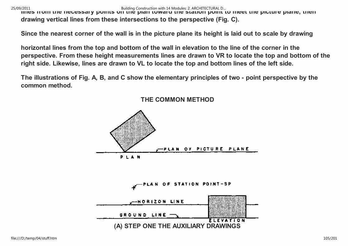
- THE AUXILIARY DRAWINGS are a plan and elevation. The plan of the object, picture plane, and station
point is drawn with the picture plane line horizontal (fig. A). The elevation is drawn and the horizon line
and ground line placed to suit it.
The horizon line is at the height of the eye of the observer. The ground line is drawn at the bottom of the
elevation. The station point should be approximately on a line perpendicular to the picture plane through
the center of the plan.
- THE VANISHING POINTS are located on the horizon line in the following manner (fig. B). From the
station point SP lines are drawn parallel to the two typical sets of horizontal lines of the plan to meet the
picture plane. From these intersections A and B vertical lines are drawn to the horizon to locate the two
vanishing points, VL and VR. All of the horizontal lines of the object which are parallel to the line SP-B in
plan vanish in VR in the perspective drawing. Likewise, all of the horizontal lines of the object which are
parallel to the line SP-A in plan vanish in VL in the perspective drawing.
- MAKING THE PERSPECTIVE requires the use of a plan and elevation. The horizontal spacing of all
points and vertical lines of the perspective drawing are obtained from the plan. This is done by drawing
lines from the necessary points on the plan toward the station point to meet the picture plane, then
25/09/2011 Building Construction with 14 Modules: 2. ARCHITECTURAL D…
file:///D:/temp/04/stuff.htm 104/201
lines from the necessary points on the plan toward the station point to meet the picture plane, then
drawing vertical lines from these intersections to the perspective (Fig. C).
Since the nearest corner of the wall is in the picture plane its height is laid out to scale by drawing
horizontal lines from the top and bottom of the wall in elevation to the line of the corner in the
perspective. From these height measurements lines are drawn to VR to locate the top and bottom of the
right side. Likewise, lines are drawn to VL to locate the top and bottom lines of the left side.
The illustrations of Fig. A, B, and C show the elementary principles of two - point perspective by the
common method.
THE COMMON METHOD
(A) STEP ONE THE AUXILIARY DRAWINGS
25/09/2011 Building Construction with 14 Modules: 2. ARCHITECTURAL D…
file:///D:/temp/04/stuff.htm 105/201

(B) STEP TWO LOCATING THE VANISHING POINTS
25/09/2011 Building Construction with 14 Modules: 2. ARCHITECTURAL D…
file:///D:/temp/04/stuff.htm 106/201

(C) STEP THREE MAKING THE PERSPECTIVE
25/09/2011 Building Construction with 14 Modules: 2. ARCHITECTURAL D…
file:///D:/temp/04/stuff.htm 107/201
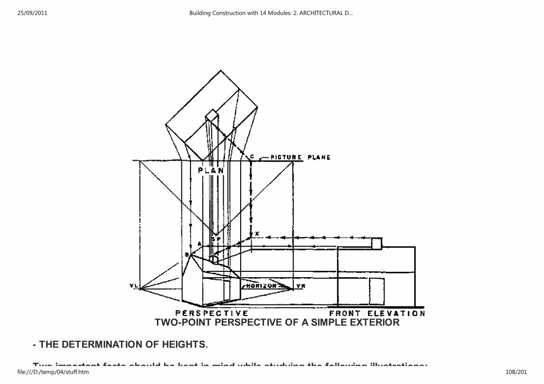
TWO-POINT PERSPECTIVE OF A SIMPLE EXTERIOR
- THE DETERMINATION OF HEIGHTS.
Two important facts should be kept in mind while studying the following illustrations:
25/09/2011 Building Construction with 14 Modules: 2. ARCHITECTURAL D…
file:///D:/temp/04/stuff.htm 108/201

Two important facts should be kept in mind while studying the following illustrations:
1. All heights are laid out to scale in the picture plane only,
2. Heights are carried from their scale sizes in the picture plane into correct perspective
positions by tracing them along lines which vanish in the vanishing points and lead to the on the
object where the heights are used.
- THE LOCATION OF THE STATION POINT.
The pictorial effect obtained in a perspective drawing is determined by the position of the station point.
Since it would be possible to have the eye of the observer in any one of an infinite number of positions
in viewing an object it is possible to have an infinite number of different perspective drawings of the
object.
The location of the station point can be varied in three ways:
1. distance from the object
2. height
3. angle of view.
These variations and their effects on the perspective are discussed in the following paragraphs. The
general theory applies to interiors as well as exteriors.
25/09/2011 Building Construction with 14 Modules: 2. ARCHITECTURAL D…
file:///D:/temp/04/stuff.htm 109/201

DISTANCE FROM STATION POINT TO OBJECT
THE DISTANCE FROM THE STATION POINT TO THE OBJECT influences the pictorial effect and size of
the perspective. When the station point is near the object the horizontal lines not parallel to the picture
plane slant sharply (Fig. A). As the distance from the object is increased the horizontal lines flatten out
and the perspective approaches the form of an elevation perpendicular to the picture plane in which all
horizontal lines are parallel and horizontal (Fig. B and C). Parts of the object which are in front of the
picture plane become smaller as the distance from the object to the station point increases, and parts
behind the picture plane become larger. Both approach scale size as the distance increases and
conversely, both vary more from scale size as the distance diminishes. When the station point is near
the object the bottoms of horizontal surfaces above the horizon are large, as are the top surfaces of
horizontal areas below the horizon. As the station point moves farther away these areas become smaller
and disappear from view when the station point is at infinity (Fig. A, B, and C).
25/09/2011 Building Construction with 14 Modules: 2. ARCHITECTURAL D…
file:///D:/temp/04/stuff.htm 110/201
The maximum angle of vision of the eye is usually assumed to be 45° or 60. This angle should include
everything shown in the perspective. When the height of the object is greater than its width the height
will determine the angle of vision. In one-point perspective the limit of vision is considered to be a cone
of rays from the eye, thus avoiding the distorted effect sometimes found in the corners of one-point
perspectives. To avoid excessive distortion in perspectives of spheres and circles, these shapes should
be kept within a 30° cone of vision in any type of perspective.
As a practical consideration the farther the station point is located from the object, the greater the
distance from the drawings to the various centers of converging lines. It is usually desired that these
centers be in reach of the T-square for drawing lines and that they be on the area of the board. When
the picture effect of the perspective is entirely satisfactory it is more convenient to keep all centers of
converging lines on the board.
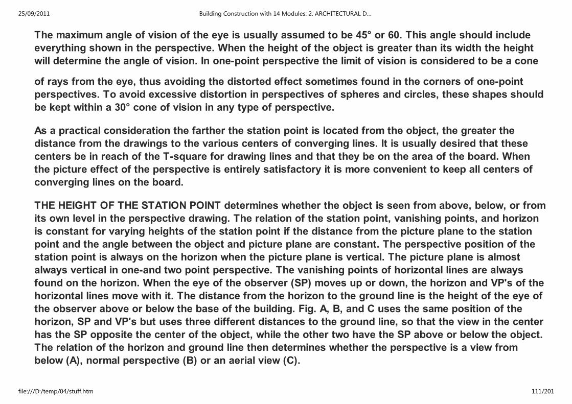
THE HEIGHT OF THE STATION POINT determines whether the object is seen from above, below, or from
its own level in the perspective drawing. The relation of the station point, vanishing points, and horizon
is constant for varying heights of the station point if the distance from the picture plane to the station
point and the angle between the object and picture plane are constant. The perspective position of the
station point is always on the horizon when the picture plane is vertical. The picture plane is almost
always vertical in one-and two point perspective. The vanishing points of horizontal lines are always
found on the horizon. When the eye of the observer (SP) moves up or down, the horizon and VP's of the
horizontal lines move with it. The distance from the horizon to the ground line is the height of the eye of
the observer above or below the base of the building. Fig. A, B, and C uses the same position of the
horizon, SP and VP's but uses three different distances to the ground line, so that the view in the center
has the SP opposite the center of the object, while the other two have the SP above or below the object.
The relation of the horizon and ground line then determines whether the perspective is a view from
below (A), normal perspective (B) or an aerial view (C).
25/09/2011 Building Construction with 14 Modules: 2. ARCHITECTURAL D…
file:///D:/temp/04/stuff.htm 111/201

PLAN FOR ALL VIEWS
25/09/2011 Building Construction with 14 Modules: 2. ARCHITECTURAL D…
file:///D:/temp/04/stuff.htm 112/201
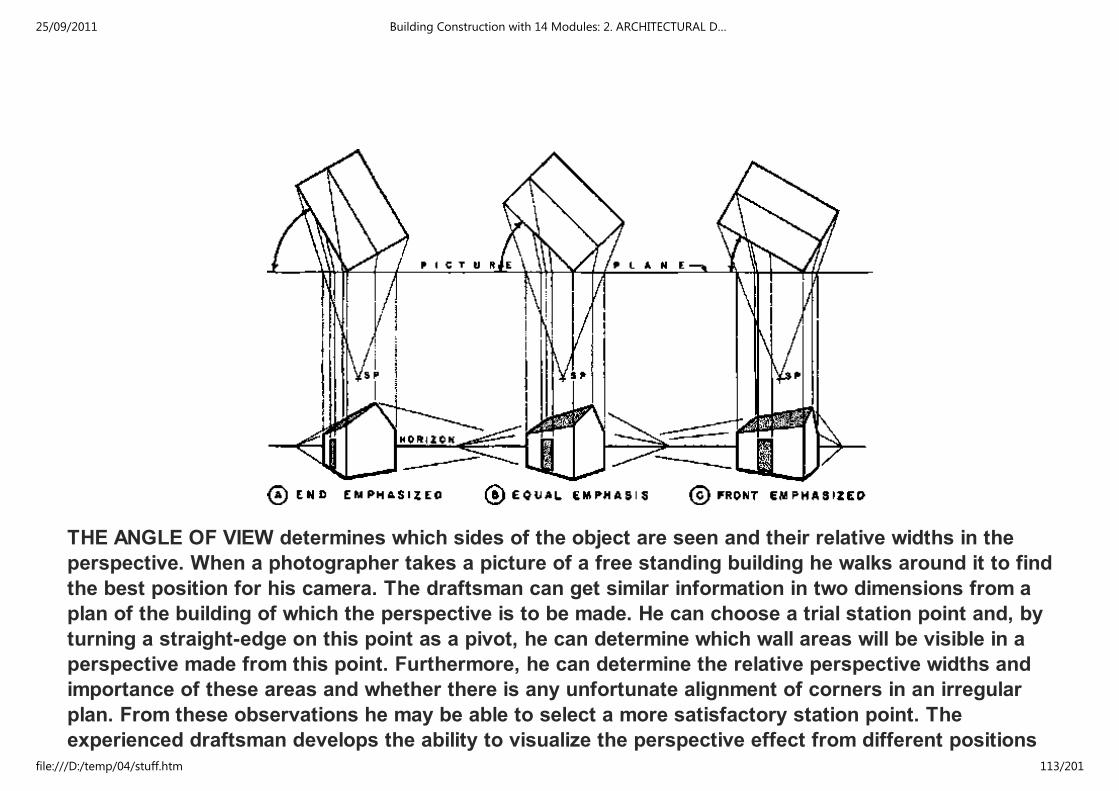
THE ANGLE OF VIEW determines which sides of the object are seen and their relative widths in the
perspective. When a photographer takes a picture of a free standing building he walks around it to find
the best position for his camera. The draftsman can get similar information in two dimensions from a
plan of the building of which the perspective is to be made. He can choose a trial station point and, by
turning a straight-edge on this point as a pivot, he can determine which wall areas will be visible in a
perspective made from this point. Furthermore, he can determine the relative perspective widths and
importance of these areas and whether there is any unfortunate alignment of corners in an irregular
plan. From these observations he may be able to select a more satisfactory station point. The
experienced draftsman develops the ability to visualize the perspective effect from different positions
around the plan of the object and thus choose the station point best suited to his purpose. The relative
25/09/2011 Building Construction with 14 Modules: 2. ARCHITECTURAL D…
file:///D:/temp/04/stuff.htm 113/201
around the plan of the object and thus choose the station point best suited to his purpose. The relative
importance of the sides shown in the perspective has probably the area test influence on the angle of
view. Ordinarily it is desirable to look more directly at the important side and less directly at the
unimportant one. In most perspectives of exteriors the entrance to the building is considered as an
essential. A reasonable amount of the entrance should be visible when the shape of the building does
not allow all of it to be shown from the chosen direction. When a model of the proposed building is
available it is very useful in selecting a station point. All three of the variables can be considered with a
model. The figure shows three views of the same object from different angles.
Regardless of the angle from which the object is seen, the station point should always be located
approximately on a line through the center of the plan and perpendicular to the picture plane. The
perspective is distorted when the station point is located very far to one side of this line. It is a great
temptation where the plan is set up and the correctly located station point does not give satisfactory
results, to take the easy way out and push the station point to one side. However, such a procedure
causes the perpendicular to the picture plane to be off center on the plan and perspective. It will,
therefore, cause the perspective to be out of proportion.
THE POSITION OF THE PICTURE PLANE. The size of the perspective drawing obtained with a given
object, given scale, and given relation between station point and object, can be varied by changing the
position of the picture plane (fig. A, B, and C) The nearer the picture plane to the station point the
smaller the perspective, the farther the picture plane from the station point the, larger the perspective. If
all positions of the picture plane are parallel the resulting perspective drawings will be identical in all
respects except size. The shifting of the position of the picture plane is a very helpful device for
obtaining any size perspective desired. However, there are limits to its use. Extreme enlargements may
be lacking in accuracy, while extreme reductions in size require space for the construction which is out
of proportion to the size of the resulting perspective drawing. The most common position of the picture
plane is through the nearest main corner of the object. Simplicity and directness of construction are the
principal advantages of this location of the picture plane. However, similar advantages are secured by
having the picture plane pass through any visible corner of the object. Other positions of the picture
25/09/2011 Building Construction with 14 Modules: 2. ARCHITECTURAL D…
file:///D:/temp/04/stuff.htm 114/201
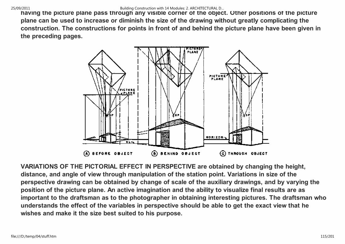
having the picture plane pass through any visible corner of the object. Other positions of the picture
plane can be used to increase or diminish the size of the drawing without greatly complicating the
construction. The constructions for points in front of and behind the picture plane have been given in
the preceding pages.
VARIATIONS OF THE PICTORIAL EFFECT IN PERSPECTIVE are obtained by changing the height,
distance, and angle of view through manipulation of the station point. Variations in size of the
perspective drawing can be obtained by change of scale of the auxiliary drawings, and by varying the
position of the picture plane. An active imagination and the ability to visualize final results are as
important to the draftsman as to the photographer in obtaining interesting pictures. The draftsman who
understands the effect of the variables in perspective should be able to get the exact view that he
wishes and make it the size best suited to his purpose.
25/09/2011 Building Construction with 14 Modules: 2. ARCHITECTURAL D…
file:///D:/temp/04/stuff.htm 115/201

When several perspective studies are made from a given design and none of them looks well, the
designer may be reluctantly forced to the conclusion that he has not designed a beautiful building. It is
even more difficult for the draftsman to make a dramatic perspective of a mediocre design than for the
photographer to make a glamorous photograph of a homely person. Furthermore, the architect must
prove the design in the actual building, and there is a question of professional integrity involved.
25/09/2011 Building Construction with 14 Modules: 2. ARCHITECTURAL D…
file:///D:/temp/04/stuff.htm 116/201

BLOCK STUDIES AT SMALL SCALE, which show only the masses and principal features of the object,
can be made very quickly. They are of great value in choosing a station point for a larger and more
detailed perspective drawing. They often save time because the large perspective can be made correctly
the first time. With several possible variations considered in block form a better pictorial effect can be
secured. These simple preliminary studies may be compared to the proofs furnished by a photographer.
One of the proofs is selected for the final pictures or perspective.
While the beginner in perspective drawing needs the information from a number of block studies, he is
usually not as willing to make them as the expert draftsman who appreciates their value from experience.
On these speedy drawings the designer feels free to try arrangements which he would be very unlikely
to try for a single large perspective. There is, therefore, a psychological advantage in a number of block
studies which leads to greater imaginative freedom, and often to more dramatic results. Freehand
studies are used by many designers for ideas for perspectives.
25/09/2011 Building Construction with 14 Modules: 2. ARCHITECTURAL D…
file:///D:/temp/04/stuff.htm 117/201

EXTERIOR BLOCK STUDIES
(A)
25/09/2011 Building Construction with 14 Modules: 2. ARCHITECTURAL D…
file:///D:/temp/04/stuff.htm 118/201

(B)
(C)
25/09/2011 Building Construction with 14 Modules: 2. ARCHITECTURAL D…
file:///D:/temp/04/stuff.htm 119/201

(D)
INTERIOR BLOCK STUDIES
(A)
25/09/2011 Building Construction with 14 Modules: 2. ARCHITECTURAL D…
file:///D:/temp/04/stuff.htm 120/201

(A)
(B)
(C)
25/09/2011 Building Construction with 14 Modules: 2. ARCHITECTURAL D…
file:///D:/temp/04/stuff.htm 121/201

(C)
(D)
THE PERSPECTIVE PLAN METHOD
25/09/2011 Building Construction with 14 Modules: 2. ARCHITECTURAL D…
file:///D:/temp/04/stuff.htm 122/201
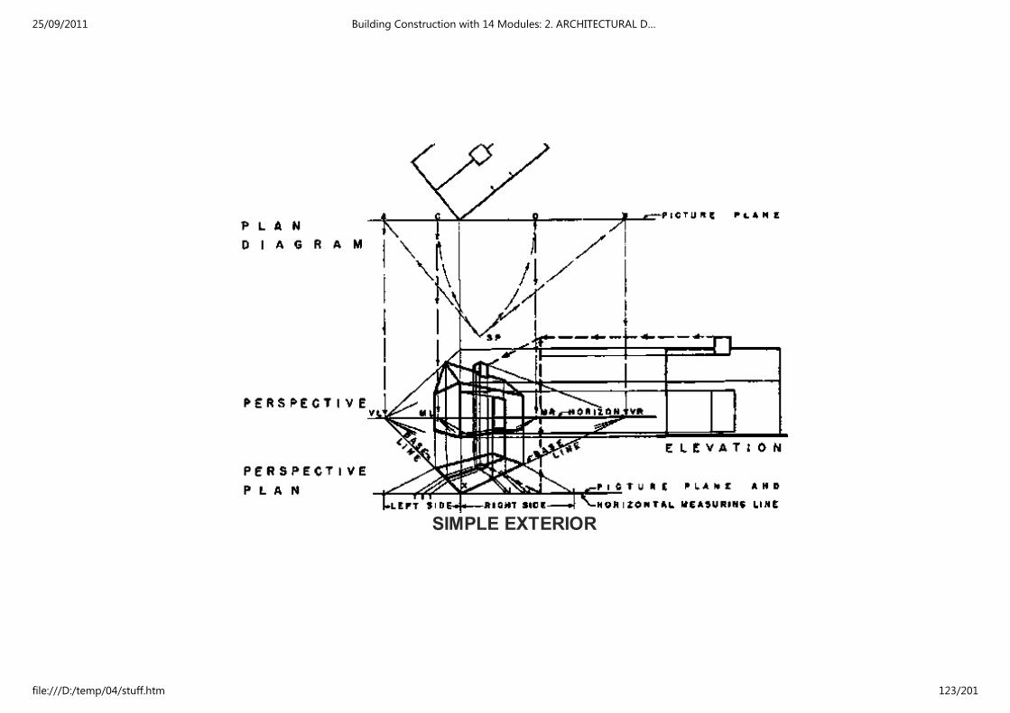
SIMPLE EXTERIOR
25/09/2011 Building Construction with 14 Modules: 2. ARCHITECTURAL D…
file:///D:/temp/04/stuff.htm 123/201

SIMPLE INTERIOR
2.4.6 ONE-POINT PERSPECTIVE
The most striking and characteristic views of streets, landscape garden scenes, groups of buildings,
single buildings, and parts of buildings both exterior and interior, often show them as they would appear
in one-point perspective. One-point perspective is therefore important to the architect and draftsman,
because it is frequently more suitable for the subject to be drawn or gives a more characteristic view
than could be obtained with two - point perspective.
25/09/2011 Building Construction with 14 Modules: 2. ARCHITECTURAL D…
file:///D:/temp/04/stuff.htm 124/201

than could be obtained with two - point perspective.
One-point perspective is so named because only one of the three typical sets of lines converges to a
vanishing point. The remaining two sets of lines are parallel to the picture plane. Since lines which are
parallel to the picture plane retain their true directions, the lines of each of these two sets remain parallel
in perspective. In most one-point perspectives the picture plane is vertical. The vertical lines and one set
of horizontal lines of the object are parallel to the picture plane, and remain respectively vertical and
horizontal in the perspective drawing. The remaining set of horizontal lines is perpendicular to the
picture plane and converges to a vanishing point.
One-point perspective can be used appropriately and effectively whenever the object presents a good
appearance with the line of the center of vision of the observer perpendicular to one set of planes of the
object, and consequently parallel to one set of lines; that is, when the conditions under which the object
is naturally seen are those of one-point perspective.
Typical subjects for one-point perspectives are shown in the illustrations of the figure.
25/09/2011 Building Construction with 14 Modules: 2. ARCHITECTURAL D…
file:///D:/temp/04/stuff.htm 125/201

Although one-point perspective is not as widely used as two-point perspective it is extremely useful for
both exterior and interior subjects and deserves the careful study and consideration of the person who
wishes to become proficient in perspective drawing. Some of the most striking photographs used in
25/09/2011 Building Construction with 14 Modules: 2. ARCHITECTURAL D…
file:///D:/temp/04/stuff.htm 126/201

wishes to become proficient in perspective drawing. Some of the most striking photographs used in
illustrations of architectural magazines are one-point perspective views. Since the photographer usually
has a wide range of choice of views, the one-point perspective position is chosen in most cases because
of its pictorial merits and not from necessity.
THE COMMON METHOD OF ONE-POINT PERSPECTIVE. The use of a plan showing the object, picture
plane, and station point is required for the construction of the perspective drawing.
Step I of the figure shows the location of the plan and elevation as the first step in making the
perspective. The elevation is in this example located below the station point of the plan and to the right
of the edge of the plan to leave a clear area for the perspective drawing. The horizon has been located
near the center of the height of the elevation.
STEP I - ARRANGING THE AUXILIARY DRAWINGS
In Step II vertical lines are drawn from plan and horizontal lines from the elevation to give the
intersection of walls, floor, and ceiling of the room with the picture plane. This line of intersection is at
scale size since it Ties in the picture plane. The vanishing point is located by drawing a vertical line from
the plan of the station point to meet the horizon. When the position of one end of a line perpendicular to
the picture plane has been located in the perspective drawing the line can then be drawn through this
25/09/2011 Building Construction with 14 Modules: 2. ARCHITECTURAL D…
file:///D:/temp/04/stuff.htm 127/201
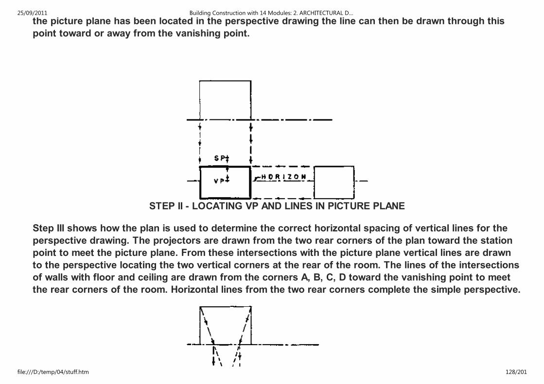
the picture plane has been located in the perspective drawing the line can then be drawn through this
point toward or away from the vanishing point.
STEP II - LOCATING VP AND LINES IN PICTURE PLANE
Step III shows how the plan is used to determine the correct horizontal spacing of vertical lines for the
perspective drawing. The projectors are drawn from the two rear corners of the plan toward the station
point to meet the picture plane. From these intersections with the picture plane vertical lines are drawn
to the perspective locating the two vertical corners at the rear of the room. The lines of the intersections
of walls with floor and ceiling are drawn from the corners A, B, C, D toward the vanishing point to meet
the rear corners of the room. Horizontal lines from the two rear corners complete the simple perspective.
25/09/2011 Building Construction with 14 Modules: 2. ARCHITECTURAL D…
file:///D:/temp/04/stuff.htm 128/201
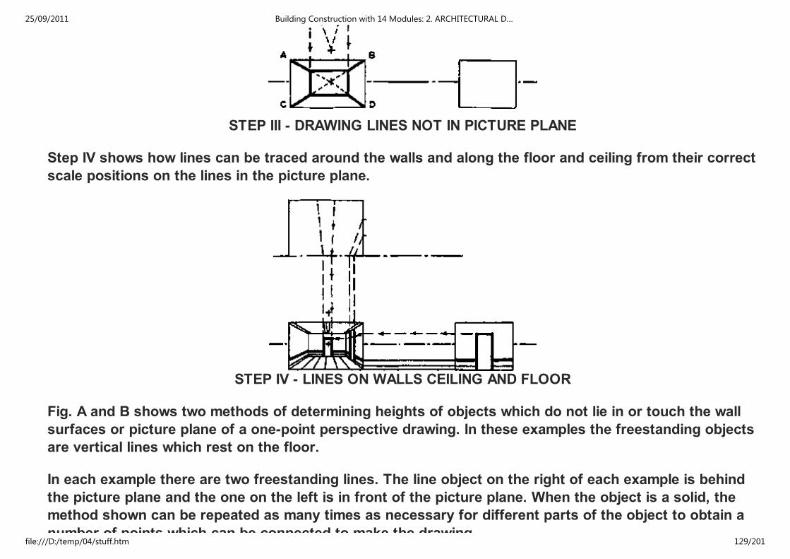
STEP III - DRAWING LINES NOT IN PICTURE PLANE
Step IV shows how lines can be traced around the walls and along the floor and ceiling from their correct
scale positions on the lines in the picture plane.
STEP IV - LINES ON WALLS CEILING AND FLOOR
Fig. A and B shows two methods of determining heights of objects which do not lie in or touch the wall
surfaces or picture plane of a one-point perspective drawing. In these examples the freestanding objects
are vertical lines which rest on the floor.
In each example there are two freestanding lines. The line object on the right of each example is behind
the picture plane and the one on the left is in front of the picture plane. When the object is a solid, the
method shown can be repeated as many times as necessary for different parts of the object to obtain a
number of points which can be connected to make the drawing.
25/09/2011 Building Construction with 14 Modules: 2. ARCHITECTURAL D…
file:///D:/temp/04/stuff.htm 129/201
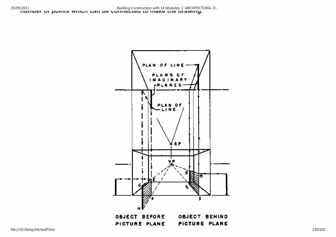
number of points which can be connected to make the drawing.
(A) DIRECT METHOD
25/09/2011 Building Construction with 14 Modules: 2. ARCHITECTURAL D…
file:///D:/temp/04/stuff.htm 130/201

(A) DIRECT METHOD
IN THE DIRECT METHOD, Fig., an imaginary plane which is parallel to the side walls of the perspective
drawing and perpendicular to the picture plane is extended through the point plan of the freestanding
line to meet the picture plane in plan. The height of the line is laid out to scale on the line E-F of
intersection of the imaginary plane and picture plane in the perspective drawing. The height is then
traced directly along the imaginary plane by lines through the vanishing point and brought to correct
perspective position at G-H as shown. This is the most convenient and simple method of deter- mining
most heights of freestanding objects. However, in the special case when the freestanding line is on a
vertical through the vanishing point this method cannot be used, because the line from the vanishing
point is a vertical line and will not intersect vertical lines brought down from plan to establish heights.
Furthermore, the lines from the vanishing point must be at a sufficient angle, so that their intersections
with vertical lines can be accurately located. Objects which are very near a vertical line through the
vanishing point cannot be accurately located by this method.
25/09/2011 Building Construction with 14 Modules: 2. ARCHITECTURAL D…
file:///D:/temp/04/stuff.htm 131/201

25/09/2011 Building Construction with 14 Modules: 2. ARCHITECTURAL D…
file:///D:/temp/04/stuff.htm 132/201

(B) INDIRECT METHOD
THE INDIRECT METHOD carries the heights along the walls or other planes perpendicular to the picture
plane to the required distance, then along imaginary planes parallel to the picture plane to the correct
perspective position. In the two examples of Fig. the wall serves as the plane perpendicular to the
picture plane for the object behind the picture plan. An extension of the wall has been used for the
object in front of the picture plane.
The three examples of one-point perspective by the common method (see figures) show the application
of principles previously explained to more detailed subjects. An elevation or section has been drawn in
each example in order to make the methods of determining heights as clear as possible. It is not
necessary to draw the elevation or section as a part of the construction of a perspective by the common
method.
The heights and widths of the parts of the object in the picture plane are drawn to scale size.
In the figure the ends of the projecting wings of the building lie in the picture plane and are drawn to
scale size by dropping verticals from plan to meet horizontals from elevation. The top and bottom lines
of the wings, which are perpendicular to the picture plane, are drawn to the vanishing point to meet the
construction lines brought down from the junction of the wings and main building in plan. The indirect
method is used to determine the height of the flagpole since it is too nearly on a vertical line through the
vanishing point to use the direct method accurately. These construction lines are heavy dotted lines.
The height of the roof is traced back into position by the direct method using an extension of the end
wall to the picture plane for the height construction.
25/09/2011 Building Construction with 14 Modules: 2. ARCHITECTURAL D…
file:///D:/temp/04/stuff.htm 133/201

ELEMENTS OF ONE-POINT PERSPECTIVE - COMMON METHOD
25/09/2011 Building Construction with 14 Modules: 2. ARCHITECTURAL D…
file:///D:/temp/04/stuff.htm 134/201

EXTERIOR
In the figure the lines made of short dots on the right side of the perspective show the construction of
heights by tracing around hidden surfaces. The lines with longer dots and arrows in this example show
the construction of a height, by the direct method, around one imaginary corner. The indirect method is
used to determine the height of the highest point of the building.
The figure illustrates the tracing of heights around visible wall surfaces for the wainscoting, windows,
and ceiling line. The height of the rectangular box is found by the indirect method, using an imaginary
25/09/2011 Building Construction with 14 Modules: 2. ARCHITECTURAL D…
file:///D:/temp/04/stuff.htm 135/201

and ceiling line. The height of the rectangular box is found by the indirect method, using an imaginary
extension of a plane of the box to meet the wall. The lines of the sofa are projected directly from the
scale profile (drawn in dotted lines) in the picture plane to position in the perspective drawing.
INTERIOR
VARIABLES
25/09/2011 Building Construction with 14 Modules: 2. ARCHITECTURAL D…
file:///D:/temp/04/stuff.htm 136/201

LOCATION OF THE PICTURE PLANE
HEIGHT OF STATION POINT
HORIZONTAL POSITION OF STATION POINT
DISTANCE OF STATION POINT FROM OBJECT
25/09/2011 Building Construction with 14 Modules: 2. ARCHITECTURAL D…
file:///D:/temp/04/stuff.htm 137/201

DISTANCE OF STATION POINT FROM OBJECT
EXAMPLES
EXTERIOR ONE-POINT PERSPECTIVE
25/09/2011 Building Construction with 14 Modules: 2. ARCHITECTURAL D…
file:///D:/temp/04/stuff.htm 138/201

INTERIOR ONE-POINT PERSPECTIVE
2.5 SHADES AND SHADOWS
Wherever there are buildings, clouds, trees, rocks, or other objects extending above the surface of land
or water there are shadows when the sun shine. These shadows form an essential part of the pattern of
a landscape, a piece of pottery, or a building. Since shadows are inevitably a part of any object which is
to be placed in the light, their forms and masses must be considered in studying a design if that design
is to be completely successful.
25/09/2011 Building Construction with 14 Modules: 2. ARCHITECTURAL D…
file:///D:/temp/04/stuff.htm 139/201

(A) DISTINCTION BETWEEN SHADE AND SHADOW
A knowledge of shadow shapes and of the methods by which they are correctly and accurately
constructed on various types of drawings is an essential part of the training of any draftsman or
designer of objects in three dimensions.
(B) SHADOW WIDTHS MAY EQUAL PROJECTIONS
25/09/2011 Building Construction with 14 Modules: 2. ARCHITECTURAL D…
file:///D:/temp/04/stuff.htm 140/201

2.5.1 THE USE OF SHADOWS
Shadows are especially useful in architectural drawing and design because they make the drawings more
easily understood. The shades and shadows express the shapes of surfaces, showing whether they are
curved or flat, slanting or vertical. In drawings shadows are especially valuable because they bring out
the third dimension; the distance back, in what would otherwise be a two-dimension drawing. The lines
and masses of shadows form an important part of an architectural design and should be a part of the
studies made in the development of the design. When the correctly drawn shadows are unpleasant or
disturbing there is something wrong with the design and it should be revised to produce a more
harmonious effect.
(C) THE CONVENTIONAL DIRECTION OF LIGHT
Shadows are almost indispensable on rendered presentation drawings. They add to the picture effect of
drawings, making them much more easily understood by the client. The rendered shadows give even the
designer a clearer conception of the appearance of the projected building and aid him in perfecting its
design.
25/09/2011 Building Construction with 14 Modules: 2. ARCHITECTURAL D…
file:///D:/temp/04/stuff.htm 141/201

(D) TRUE DIRECTION OF A CONVENTIONAL RAY
DEFINITION OF SHADOW TERMS
2.5.2 SHADES AND SHADOWS
(I) THE SHADE LINES CAST SHADOW OUTLINES
A shade occurs when the shape of the object excludes the light rays from part of its surface (Fig. A) The
lines between the areas of light and shade are called shade lines. On a curving surface, such as that of a
sphere, the shade line is the line of tangency of light rays to the curving surface. On objects made up of
plane surfaces a shade line is the edge where a surface in light meets a surface in shade. A shadow
travels through the air from one object to another, or from one part of an object to another part of the
same object.
25/09/2011 Building Construction with 14 Modules: 2. ARCHITECTURAL D…
file:///D:/temp/04/stuff.htm 142/201

(II) SHADOW SEEN IN A PICTORIAL DRAWING
2.5.3 THE CONVENTIONAL DIRECTION OF LIGHT
In casting shadows it is necessary to assume a source and direction of light. The source of light is
usually assumed to be the sun and the rays of light are considered to be parallel The direction of light
used in practically all shadow-casting gives shadow widths which are equal to the projections from wall
surfaces of vertical and horizontal shade lines which are parallel to the picture plane and the wall.
Characteristic examples of shadows which are equal to the projections making them are those of the
cornice and window shown in fig. B.
25/09/2011 Building Construction with 14 Modules: 2. ARCHITECTURAL D…
file:///D:/temp/04/stuff.htm 143/201

(III) SHADOW SEEN IN THE MULTI-VIEW DRAWINGS
If a cube is placed so that its sides are parallel to the three coordinate planes of elevation, plan, and side
elevation, then its diagonal from the top left front corner to the lower right rear corner gives the
conventional direction of light and the three views of the cube give the apparent directions of light in the
three typical drawings (fig. C).
(IV) SIMPLE MODELS HELP TO EXPLAIN SHADOWS
2.5.4 THE 45° DIRECTION
Since the direction of light in front elevation, plan, and side elevation views is the diagonal of a square it
is a 45° line in all three drawings. Therefore, shadows may be traced by using the 45° triangle on these
drawings. A ray of light travels equally in three directions:
1. to the right
2. down, and
3. back,
25/09/2011 Building Construction with 14 Modules: 2. ARCHITECTURAL D…
file:///D:/temp/04/stuff.htm 144/201
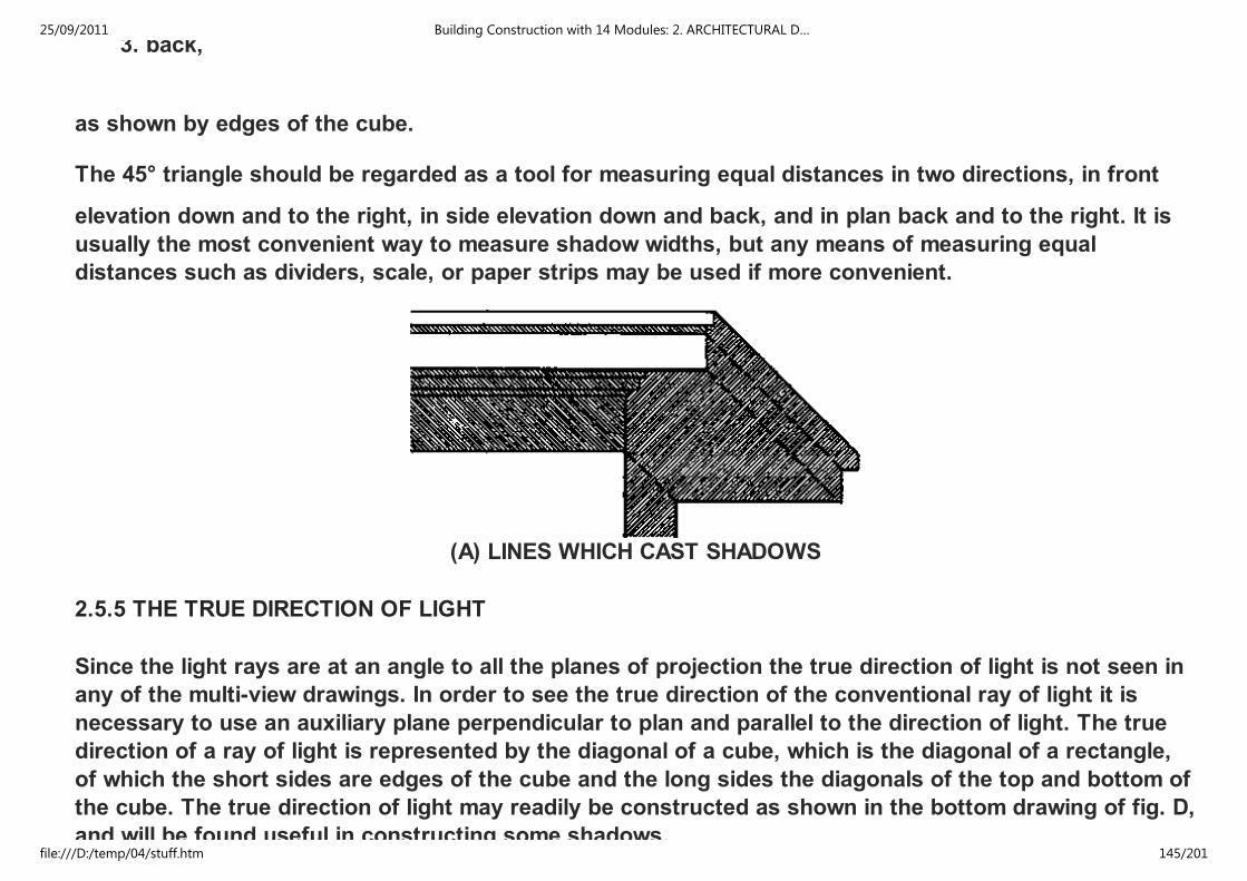
3. back,
as shown by edges of the cube.
The 45° triangle should be regarded as a tool for measuring equal distances in two directions, in front
elevation down and to the right, in side elevation down and back, and in plan back and to the right. It is
usually the most convenient way to measure shadow widths, but any means of measuring equal
distances such as dividers, scale, or paper strips may be used if more convenient.
(A) LINES WHICH CAST SHADOWS
2.5.5 THE TRUE DIRECTION OF LIGHT
Since the light rays are at an angle to all the planes of projection the true direction of light is not seen in
any of the multi-view drawings. In order to see the true direction of the conventional ray of light it is
necessary to use an auxiliary plane perpendicular to plan and parallel to the direction of light. The true
direction of a ray of light is represented by the diagonal of a cube, which is the diagonal of a rectangle,
of which the short sides are edges of the cube and the long sides the diagonals of the top and bottom of
the cube. The true direction of light may readily be constructed as shown in the bottom drawing of fig. D,
and will be found useful in constructing some shadows.
25/09/2011 Building Construction with 14 Modules: 2. ARCHITECTURAL D…
file:///D:/temp/04/stuff.htm 145/201
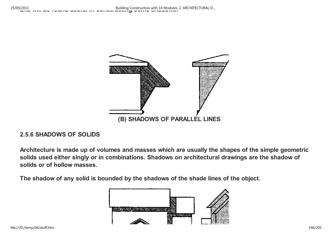
and will be found useful in constructing some shadows.
(B) SHADOWS OF PARALLEL LINES
2.5.6 SHADOWS OF SOLIDS
Architecture is made up of volumes and masses which are usually the shapes of the simple geometric
solids used either singly or in combinations. Shadows on architectural drawings are the shadow of
solids or of hollow masses.
The shadow of any solid is bounded by the shadows of the shade lines of the object.
25/09/2011 Building Construction with 14 Modules: 2. ARCHITECTURAL D…
file:///D:/temp/04/stuff.htm 146/201

(C) SHADE LINES PARALLEL TO SURFACE RECEIVING SHADOW
Only those lines which mark the divisions between light and shade on an object can cast shadows.
There fore, if the shade lines on the drawings of an object can be located by inspection, the shadows of
these shade lines can then be determined to give the outline of the shadow of the object.
(D) SHADE LINES PARALLEL TO LINES IN SHADOW SURFACE
PRINCIPLES OF SHADES AND SHADOWS
2.5.7 PLANES OF SHADOW
The straight shade lines of an object make planes of shadow. Therefore the shadows of these straight
lines are the intersections of their planes of shadow with the surfaces on which the shadows fall.
1. The position of the shade line
2. the location of the eye of the observer
3. the direction of light, and
25/09/2011 Building Construction with 14 Modules: 2. ARCHITECTURAL D…
file:///D:/temp/04/stuff.htm 147/201

3. the direction of light, and
4. the shape of the surface on which the plane of shadow ends are the factors which determine
the shape of the shadow as shown on the drawing.
2.5.8 PRINCIPLES OF SHADOW-CASTING
A knowledge of some of the simple geometric and self-evident principles used in casting shadows will
make the problems of working out shadows more easily understood. Several of these helpful principles
are described in the numbered paragraphs, and illustrated on this and the following page. The use of a
light and a simple model will help the reader to verify and understand these principles.
1 - A LINE IN SHADE OR SHADOW CANNOT CAST A SHADOW because light does not strike it. The lines
of the moldings underneath the cornice in fig. A are entirely in shadow and do not cast shadows. When
part of a line is a shade line in light and part of the line is in shadow, then only the part of the line which
is in light will cast a shadow. The corner of the wall in fig. A is an example of a line which is partly in light
and partly in shadow. By first determining which parts of the object are in shadow it is possible to locate
the shadow of the object without wasting time finding the shadows of lines which do not make parts of
the shadow outlines.
2 - SHADOWS OF PARALLEL LINES ARE PARALLEL when they fall on the same plane or on parallel
planes (fig. B). This is true regardless of the relation of the parallel lines to the plane receiving the
shadow and of the direction of the plane receiving the shadow. This principle can often be applied to
problems to simplify the working out of shadows of parallel lines and to secure greater accuracy. In the
case of slanting shadow lines such as those from the dormer onto the roof the direction can be
determined most accurately from the longest shadow; then the others can be drawn parallel to it. When
the direction of a shadow line is known the construction of the shadow is simplified.
3 - THE SHADOW IS PARALLEL TO THE LINE MAKING THE SHADOW
1. when the line is parallel to the plane receiving the shadow, or
25/09/2011 Building Construction with 14 Modules: 2. ARCHITECTURAL D…
file:///D:/temp/04/stuff.htm 148/201

1. when the line is parallel to the plane receiving the shadow, or
2. the line is parallel to the straight lines in the surface receiving the shadow.
The shadows on the house of Fig. C illustrate the first condition. The shadow of the cornice onto the
wall below, the shadow of the vertical corner of the wall onto the second wall surface and the shadow of
the right edge of the main roof onto the parallel lower roof surface are all illustrations of this principle.
The second condition is illustrated by the molding and the shadow of the vertical line onto a vertical
cylinder in Fig. D.
4 - THE SHADOW OF ANY PLANE FIGURE ON A PARALLEL PLANE is identical in shape size, and
direction with the figure. This relation is true regardless of the angle at which the area and the parallel
plane are turned (fig.). When part of the shadow is behind the plane figure making the shadow, as in the
center example, the visible part of the shadow is identical with the part of the figure which makes the
shadow. When the plane figure is part of a solid, as in the case of the example of the block on the right
of Fig. I, then the part of the shadow made by the end of the block follows this rule since it is parallel to
the plane receiving the shadow.
(I) SHADOWS OF PLANE FIGURES
25/09/2011 Building Construction with 14 Modules: 2. ARCHITECTURAL D…
file:///D:/temp/04/stuff.htm 149/201

(I) SHADOWS OF PLANE FIGURES
5 - A SHADOW IS VISIBLE only where it falls on a visible surface which is in light. The triangular shadow
below the left edge of the dormer roof in Fig. II is visible because it falls on the main roof. There is no
similar visible shadow at the left edge of the main roof because there is no visible surface receiving the
shadow. The block at the left of Fig. II is set out from the wall so far that none of its shadow is visible in
elevation. All of the shadow falls on the floor plane. The distance of the block on the right side is such
that part of the shadow is visible in elevation and part in plan.
(II) VISIBILITY OF SHADOWS
6 - ANY LINE ON A PLANE SURFACE APPEARS TO BE A STRAIGHT LINE WHEN THE. OBSERVER
LOOKS PARALLEL TO THE PLANE SURFACE. (Fig. III) Since the entire plane surface will be seen as a
line when the observer looks parallel to the plane, then any line in the plane will appear to be straight.
Objects, areas, and lines are shown in drawings as they would appear from a certain viewpoint.
25/09/2011 Building Construction with 14 Modules: 2. ARCHITECTURAL D…
file:///D:/temp/04/stuff.htm 150/201

(III) APPEARANCE OF LINES IN PLANE SURFACES
7 - WHEN THE OBSERVER LOOKS AT THE END OF ANY STRAIGHT LINE, so that the line is seen as a
point, then the shadow of the line will appear to be straight regardless of the shape of the surface
receiving the shadow. The line makes a plane of shadow. Since the observer is looking parallel to the line
he is also looking parallel to the plane of shadow made by the line and any line in the plane of shadow
appears to be straight. The shadow line lies in the plane of shadow and therefore appears to be a
straight line when seen parallel to the plane, as illustrated in the elevation of fig. IV. Any line seen in end
view in elevation, plan, perspective, or any other drawing will cast a straight line shadow in that view
where it is seen as a point. A simple model made of boxes and cans with either sunlight or a single
artificial light will help the reader understand this type of shadow.
(IV) SHADOWS OF LINES WHICH ARE SEEN AS POINTS
PRINCIPLES OF SHADES AND SHADOWS
2.6 DRAWING PRACTICE
The designer's language is the drawing. It formulates his statements clearly and is internationally
readable: factually, by geometrical drawings; attractively, by perspectives. A drawing helps to present
25/09/2011 Building Construction with 14 Modules: 2. ARCHITECTURAL D…
file:///D:/temp/04/stuff.htm 151/201

readable: factually, by geometrical drawings; attractively, by perspectives. A drawing helps to present
ideas and to convince the client. The architect's production drawings and perspectives are only a way of
presenting the proposed building clearly, not an end in themselves as are paintings.
(1)
(2)
25/09/2011 Building Construction with 14 Modules: 2. ARCHITECTURAL D…
file:///D:/temp/04/stuff.htm 152/201
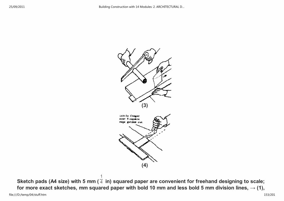
(3)
(4)
Sketch pads (A4 size) with 5 mm ( in) squared paper are convenient for freehand designing to scale;
for more exact sketches, mm squared paper with bold 10 mm and less bold 5 mm division lines, → (1),
(2). For sketching with soft pencil, thin transparent paper roll is cut to required sizes and single pieces
25/09/2011 Building Construction with 14 Modules: 2. ARCHITECTURAL D…
file:///D:/temp/04/stuff.htm 153/201

(2). For sketching with soft pencil, thin transparent paper roll is cut to required sizes and single pieces
torn off along T-square, → (3), or cut on T-square, → (4). Plans on good translucent, unglazed tracing
paper in standard sizes, → p. 2, to be used with edge protection, → (5). For ink and water colour
drawings, tracing
(5)
(6)
25/09/2011 Building Construction with 14 Modules: 2. ARCHITECTURAL D…
file:///D:/temp/04/stuff.htm 154/201

(7)
(8)
linen is best; for painting and perspectives, special papers. Fix paper to drawing board or table with clips
25/09/2011 Building Construction with 14 Modules: 2. ARCHITECTURAL D…
file:///D:/temp/04/stuff.htm 155/201

or drawing pins, not wire tacks which leave holes, → (6a). First, fold 20 mm ( in) wide edge of the paper
which later becomes the fastener hem and lifts T-square slightly off paper to avoid blurred lines (for
same reason draw from top to bottom). Then fold remaining corners 2 and 4 of
(9)
(10)
25/09/2011 Building Construction with 14 Modules: 2. ARCHITECTURAL D…
file:///D:/temp/04/stuff.htm 156/201

(11)
(12)
sheet, → (6b), pin corner in 1, smooth sheet in direction 2; after fixing this corner, repeat the action from
corner 3 to 4. Instead of drawing pins, clips or adhesive tape may be used, → (7a). Mechanical drawing
25/09/2011 Building Construction with 14 Modules: 2. ARCHITECTURAL D…
file:///D:/temp/04/stuff.htm 157/201

corner 3 to 4. Instead of drawing pins, clips or adhesive tape may be used, → (7a). Mechanical drawing
equipment originally used only by engineers is finding its way into architects offices, → (7b). In addition
to ordinary T-square, special (Patent Neufert) T-square, which makes it possible to apply various angles;
has octameter and centimetre scale, → (8).
Scale with 1 mm divisions is best, mm markings are confusing. For sketching to scale and drawing
lines at set distances, parallel rules or rolling parallel rules are useful, → (9b). Use of triangle rules is
discouraged, → (9). Best set squares are transparent uncoloured plastic with mm division, sometimes
degrees, → (10), (rigid or adjustable). Various aids to drawing circles and curves,
(13)
25/09/2011 Building Construction with 14 Modules: 2. ARCHITECTURAL D…
file:///D:/temp/04/stuff.htm 158/201

(14)
(15)
25/09/2011 Building Construction with 14 Modules: 2. ARCHITECTURAL D…
file:///D:/temp/04/stuff.htm 159/201
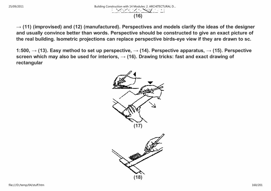
(16)
→ (11) (improvised) and (12) (manufactured). Perspectives and models clarify the ideas of the designer
and usually convince better than words. Perspective should be constructed to give an exact picture of
the real building. Isometric projections can replace perspective birds-eye view if they are drawn to sc.
1:500, → (13). Easy method to set up perspective, → (14). Perspective apparatus, → (15). Perspective
screen which may also be used for interiors, → (16). Drawing tricks: fast and exact drawing of
rectangular
(17)
(18)
25/09/2011 Building Construction with 14 Modules: 2. ARCHITECTURAL D…
file:///D:/temp/04/stuff.htm 160/201

(19)
(20)
diagrams with T-square only, without set square, → (17); correct holding of T-square and much practice
essential to success. Division of line into equal parts facilitated by putting a scale rule at slant, → (9).
Various aids, → (18), (19). Enlargement of drawings to scale through pantograph, → (20). Reduction
25/09/2011 Building Construction with 14 Modules: 2. ARCHITECTURAL D…
file:///D:/temp/04/stuff.htm 161/201

Various aids, → (18), (19). Enlargement of drawings to scale through pantograph, → (20). Reduction
compasses facilitate drawing of fixed lines in adjusted relation to original, → (20).
(21)
(22)
25/09/2011 Building Construction with 14 Modules: 2. ARCHITECTURAL D…
file:///D:/temp/04/stuff.htm 162/201
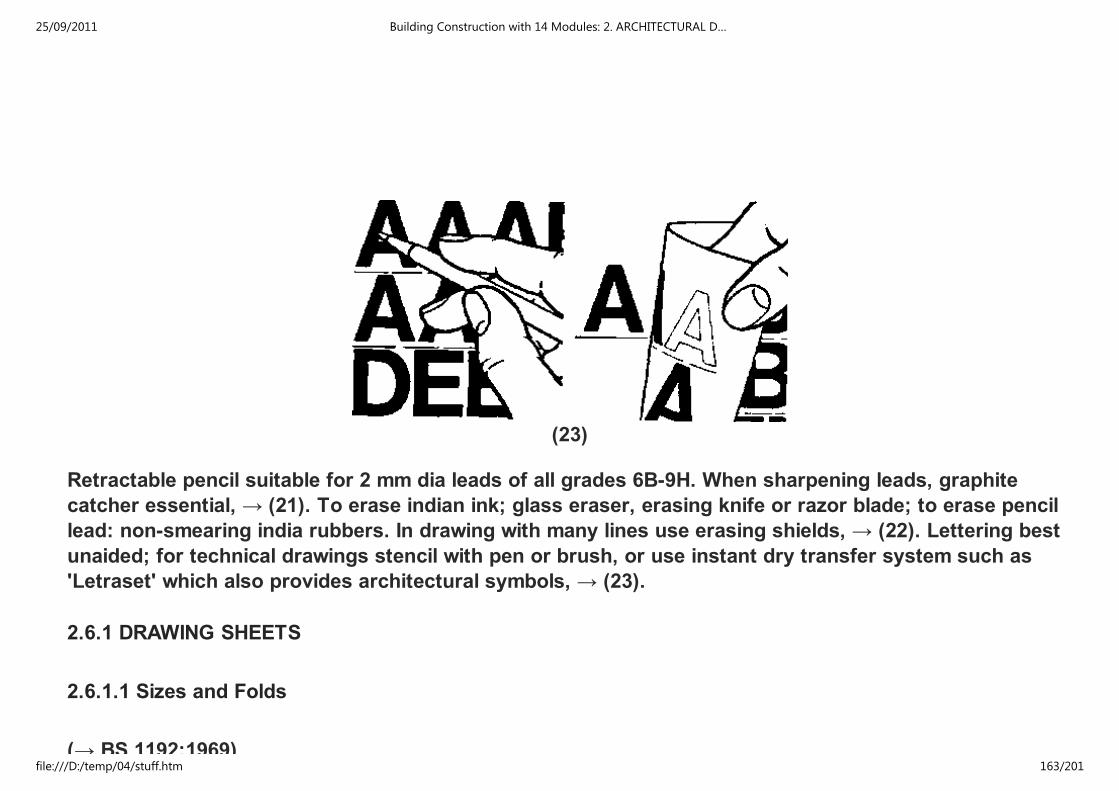
(23)
Retractable pencil suitable for 2 mm dia leads of all grades 6B-9H. When sharpening leads, graphite
catcher essential, → (21). To erase indian ink; glass eraser, erasing knife or razor blade; to erase pencil
lead: non-smearing india rubbers. In drawing with many lines use erasing shields, → (22). Lettering best
unaided; for technical drawings stencil with pen or brush, or use instant dry transfer system such as
'Letraset' which also provides architectural symbols, → (23).
2.6.1 DRAWING SHEETS
2.6.1.1 Sizes and Folds
(→ BS 1192:1969)
25/09/2011 Building Construction with 14 Modules: 2. ARCHITECTURAL D…
file:///D:/temp/04/stuff.htm 163/201

(→ BS 1192:1969)
Standard sizes
A0 841 × 1 189 mm(33 × 46 in)
A1 594 × 841 mm(23 × 33 in)
A2 420 × 594 mm(16 × 23 in)
A3 297 × 420 mm(11 × 16 in)
A4 210 × 297 mm(8 × 11 in)
These sizes are all proportional, leading to simple reduction and enlargement and sheets may be easily
folded for filing and dispatch. The relatively small sizes should lead to easier handling in the drawing
office and on site. Keep the number of sizes to minimum, to facilitate binding and reference.
Original drawings and contact copies should both be of standard sizes, therefore trimming of sheets that
makes them less than A sizes should be avoided.
Folding
Prints may be folded to A4 size quite easily from any larger A size.
When prints are to be filed it is necessary to fold them in such a way that the punch holes penetrate only
one layer. Methods of folding, → (1) and p. 3.
25/09/2011 Building Construction with 14 Modules: 2. ARCHITECTURAL D…
file:///D:/temp/04/stuff.htm 164/201

A0 (841 × 1189)
A1 (594 × 841)
25/09/2011 Building Construction with 14 Modules: 2. ARCHITECTURAL D…
file:///D:/temp/04/stuff.htm 165/201

A2 (420 × 594)
A2 (420 × 594)
A3 (297 × 420)
(1) Simple folding of drawings
25/09/2011 Building Construction with 14 Modules: 2. ARCHITECTURAL D…
file:///D:/temp/04/stuff.htm 166/201

A0 (841 × 1189)
A1 (594 × 841)
A2 (420 × 594)
25/09/2011 Building Construction with 14 Modules: 2. ARCHITECTURAL D…
file:///D:/temp/04/stuff.htm 167/201
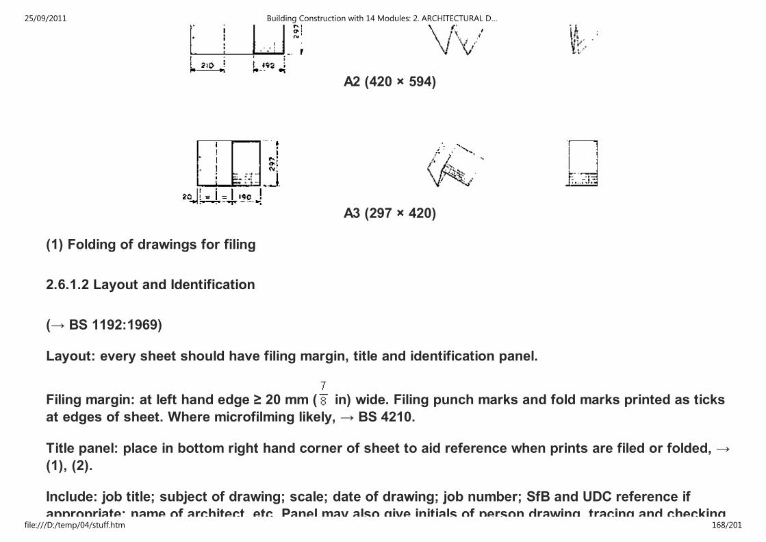
A2 (420 × 594)
A3 (297 × 420)
(1) Folding of drawings for filing
2.6.1.2 Layout and Identification
(→ BS 1192:1969)
Layout: every sheet should have filing margin, title and identification panel.
Filing margin: at left hand edge ≥ 20 mm ( in) wide. Filing punch marks and fold marks printed as ticks
at edges of sheet. Where microfilming likely, → BS 4210.
Title panel: place in bottom right hand corner of sheet to aid reference when prints are filed or folded, →
(1), (2).
Include: job title; subject of drawing; scale; date of drawing; job number; SfB and UDC reference if
appropriate; name of architect, etc. Panel may also give initials of person drawing, tracing and checking
25/09/2011 Building Construction with 14 Modules: 2. ARCHITECTURAL D…
file:///D:/temp/04/stuff.htm 168/201

appropriate; name of architect, etc. Panel may also give initials of person drawing, tracing and checking
sheet.
Revision suffix should be changed each time drawing is issued after revision.
Printed blank title panels or use of stencils, transfers or rubber stamps save time and labour.
Information panel: note nature and date of each revision, with architect's initials; start at bottom of panel
and work upwards. When general notes included, start at top and work down.
Key: on large projects give key diagram showing continuous drawing sheets, with appropriate part
blacked in on each relevant drawing.
Orientation: show north point on every plan. When practicable all plans should have same orientation,
except for site location plan. For latter, draw with north at top of sheet to aid identification with
Ordnance Survey maps.
25/09/2011 Building Construction with 14 Modules: 2. ARCHITECTURAL D…
file:///D:/temp/04/stuff.htm 169/201

(1) Typical tide panels - vertical
25/09/2011 Building Construction with 14 Modules: 2. ARCHITECTURAL D…
file:///D:/temp/04/stuff.htm 170/201

(2) Typical tide panels - horizontal
TITLE PANEL
NOTES
25/09/2011 Building Construction with 14 Modules: 2. ARCHITECTURAL D…
file:///D:/temp/04/stuff.htm 171/201

REVISIONS
SUFF. DATE INICIALS REVISION DETAILS
TCA TECHNICAL COLLEGE
CHUO CHA UFUNDI
ARUSHA
JOB TITLE DRWG. TITLE
JOB ARCHITECT REVISION SUFFIX
25/09/2011 Building Construction with 14 Modules: 2. ARCHITECTURAL D…
file:///D:/temp/04/stuff.htm 172/201

JOB ARCHITECT REVISION SUFFIX
CLIENT JOB No. DRWG No.
SIGNATURE SCALE DATE DRAWN CHECKED
2.6.2 LEVELS
Levels
(→ BS 1192:1969)
General
Levels record distance of a position above or below a defined datum.
Datum
A suitable fixed point should be taken as TBM (temporary bench mark) such that all other levels are
positive (minus sign is easily misread). This datum should be clearly indicated or described on drawings,
and all levels and vertical dimensions related to it. Vertical dimensions in metres to three decimal places
(or in feet and decimals of a foot) above this datum. On large jobs, particularly, it is usually necessary to
relate job datum to OS datum (OS levels at present in feet). State clearly whether Newlyn or Liverpool
Ordnance Datum is used.
OS are preparing bench mark lists giving heights in metres to two places of decimals.
Levels on plan
It is important to differentiate on site layout drawings between existing levels and intended levels:
25/09/2011 Building Construction with 14 Modules: 2. ARCHITECTURAL D…
file:///D:/temp/04/stuff.htm 173/201

It is important to differentiate on site layout drawings between existing levels and intended levels:
existing level: × 58.210
intended level: × 60.255
Exact position to which level applies should be indicated by 'X'
Finished floor levels should be indicated by letters FFL followed by figures of level:
FFL 12.335
Levels on section and elevation
Use same method as for levels on plan except that level should be projected beyond drawing with
arrowhead indicating appropriate line, → (1).
(1) Levels on section and elevation
25/09/2011 Building Construction with 14 Modules: 2. ARCHITECTURAL D…
file:///D:/temp/04/stuff.htm 174/201

2.6.3 REFERENCING
Referencing
Classification and coding of building components and elements shown on drawings may be achieved
through use of SfB system (UK application known as Cl/SfB; → 'Construction Indexing Manual',
published by RIBA, for details of system and its tables).
SfB enables information contained within different kinds of documents, such as bills of quantity,
drawings, specifications, texts, trade literature, etc, to be co-ordinated and correlated for maximum
benefit of user.
SfB system is a facet system of alpha-numerical symbols forming three tables which may be used
individually or in combination to indicate concepts and terms required. Three tables of SfB system cover
building elements, components/products, and materials.
Each type of component or element shown on a drawing may be identified by appropriate SfB notation,
e.g.:
concrete blocks Ff2
concrete lintels Gf2
aluminum sections Hh4
hardwood sections Hi3
manholes (52)
external walls (21)
windows (31)
25/09/2011 Building Construction with 14 Modules: 2. ARCHITECTURAL D…
file:///D:/temp/04/stuff.htm 175/201

windows (31)
doors (32)
radiators (56)
Notations may be combined, e.g.:
external walls, concrete block (21) Ff2
windows, aluminum (31) Hh4
doors, hardwood (32) Hi3
Number and length of component and element notations should be kept to minimum compatible with a
rational system of identification for each particular job.
A specific component within any range may be identified by a suffix giving nominal sizes for length,
width, height, etc:
concrete block Ff2 400 mm × 100 mm × 200 mm
Ff2 1 ft 4 in × 4 in × 8 in
Alternatively, where principles of modular coordination are applied, such a suffix may give nominal sizes
for a component or element in multiples of 100 mm or 4 in (M), e.g.:
concrete block Ff2 4M × 1M × 2M
2.6.4 ABBREVIATIONS
25/09/2011 Building Construction with 14 Modules: 2. ARCHITECTURAL D…
file:///D:/temp/04/stuff.htm 176/201

(→ BS 1192:1969)
Aggregate agg
Air brick AB
Aluminum al
Asbestos abs
Asbestos cement abs CT
Asphalt asph
Bitumen bit
Boarding bdg
Brickwork bwk
BS Universal beam BSUB
BS Channel BSC
BS equal angle BSEA
BS unequal angle BSUA
BS tee BST
Bronze metal antique BMA
Building bldg
Cast iron CI
Cement ct
25/09/2011 Building Construction with 14 Modules: 2. ARCHITECTURAL D…
file:///D:/temp/04/stuff.htm 177/201

Chromium plate CP
Cleaning eye CE
Column col
Concrete conc
Convector conv
Copper cu copp
Cupboard cpd
Damp proof course DPC
Damp proof membrane DPM
Discharge pipe DP
Drawing dwg
Expanded metal lathing EML
Foundation fdn
Fresh air inlet FAI
Glazed pipe GP
Granolithic grano
Hardcore hc
Hardboard hdt
Hardwood hwc
25/09/2011 Building Construction with 14 Modules: 2. ARCHITECTURAL D…
file:///D:/temp/04/stuff.htm 178/201
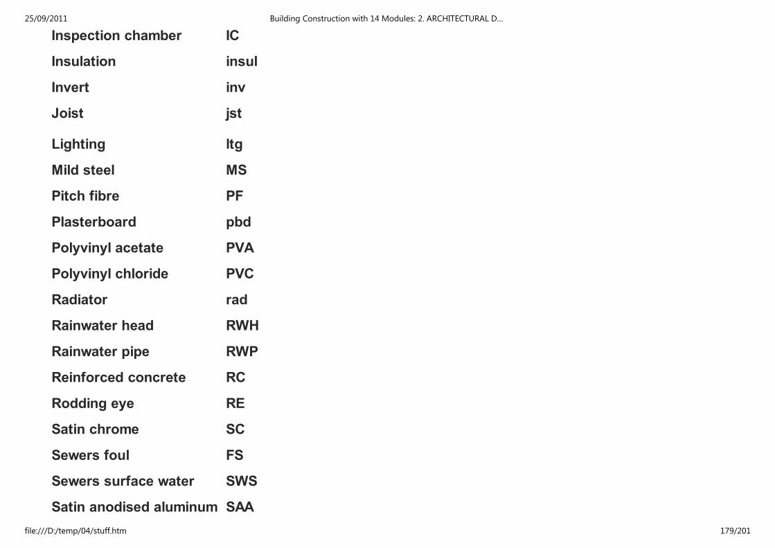
Inspection chamber IC
Insulation insul
Invert inv
Joist jst
Lighting ltg
Mild steel MS
Pitch fibre PF
Plasterboard pbd
Polyvinyl acetate PVA
Polyvinyl chloride PVC
Radiator rad
Rainwater head RWH
Rainwater pipe RWP
Reinforced concrete RC
Rodding eye RE
Satin chrome SC
Sewers foul FS
Sewers surface water SWS
Satin anodised aluminum SAA
25/09/2011 Building Construction with 14 Modules: 2. ARCHITECTURAL D…
file:///D:/temp/04/stuff.htm 179/201

Softwood swd
Stainless steel SS
Tongue and groove T&G
Unglazed pipe UGP
Vent pipe VP
Wrought iron Wl
2.6.5 REPRESENTATION OF MATERIALS
(→ BS 1192:1969)
Table shows recommended methods of indicating materials on drawings. These methods should only be
used where confusion is likely to occur in interpretation of drawings, but in all cases they should be
accompanied by a descriptive note, stating type of material, thickness, etc. Existing and proposed work
should be clearly indicated. Spacing of hatching lines should be adapted to scale of drawing and should
not normally be used on small scale drawings.
Colouring is costly, laborious and conducive to error and consequently to be avoided. Hatching is
preferable where it is necessary to show different materials.
Brick
Concrete
Earth
Fibre board
25/09/2011 Building Construction with 14 Modules: 2. ARCHITECTURAL D…
file:///D:/temp/04/stuff.htm 180/201

Fibre board
Glass
Hardcore
Loose insulation
Metal
Partition block
Plywood
Screed
Sheet membrane
Stone
Wood (unwrot)
Wood (wrot)
2.6.6 GRAPHICAL SYMBOLS AND REPRESENTATION
(→ BS 1192:1969)
A drawing is a symbolic representation of a real or imagined object. Aspects or parts of a drawing may
themselves be symbolically represented. Symbols for this purpose are termed graphical symbols, use of
which enables maximum information to be contained within the drawing, clearly and legibly, with
minimum effort.
25/09/2011 Building Construction with 14 Modules: 2. ARCHITECTURAL D…
file:///D:/temp/04/stuff.htm 181/201

Types of symbols
Principal types used in building drawing practice are graphical. Many of these, as well as other kinds of
symbols such as letters, numbers and signs, are covered by British Standards, of which the following
are relevant:
BS 108 Graphical symbols for general electrical purposes (power and lighting).
BS 1553 Graphical symbols for engineering:
Part 1 Pipes and valves
Part 4 Heating and ventilating systems.
BS 1635 Graphical symbols for fire protection drawings.
BS 1991 Letter symbols, signs and abbreviations
Part 1 General
Part 4 Structures, materials and soil mechanics.
BS 3939 Graphical symbols for electrical power, telecommunications and electronics diagrams.
Graphical symbols
Building drawing practice requires use of graphical symbols on drawings which are additional to those
covered in above British Standards. Examples of most commonly used graphical symbols are given
below
GRAPHICAL SYMBOLS AND REPRESENTATION
Draughtsmanship
Description Symbol
25/09/2011 Building Construction with 14 Modules: 2. ARCHITECTURAL D…
file:///D:/temp/04/stuff.htm 182/201
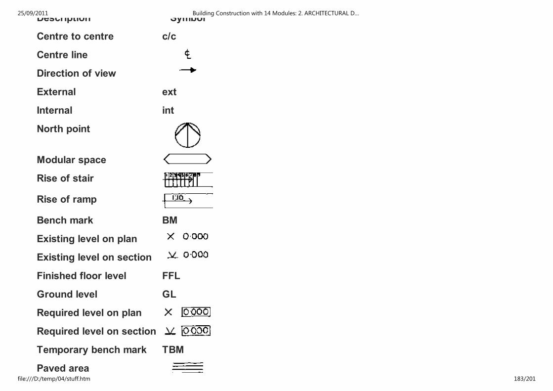
Description Symbol
Centre to centre c/c
Centre line
Direction of view
External ext
Internal int
North point
Modular space
Rise of stair
Rise of ramp
Bench mark BM
Existing level on plan
Existing level on section
Finished floor level FFL
Ground level GL
Required level on plan
Required level on section
Temporary bench mark TBM
Paved area
25/09/2011 Building Construction with 14 Modules: 2. ARCHITECTURAL D…
file:///D:/temp/04/stuff.htm 183/201

Paved area
Grass area
Planted area
New trees
Existing trees
Existing trees removed
2.6.7 HATCHING RULES
1. Draw HATCHING LINES preferably at 45 as thin lines with a spacing of - preferably - not less than 4
mm.
2. If two adjacent parts to be hatched, draw the HATCHING LINES in opposite directions.
25/09/2011 Building Construction with 14 Modules: 2. ARCHITECTURAL D…
file:///D:/temp/04/stuff.htm 184/201

3. Where more than two adjacent parts to be hatched, draw the HATCHING LINES of one area -preferably
the smallest - closer together.
4. In order to simplify distinguishing between more than two adjacent parts, HATCHING LINES drawn at
60 and/or 30 my be used additionally.
5. Large areas may be hatched along the borderline only.
25/09/2011 Building Construction with 14 Modules: 2. ARCHITECTURAL D…
file:///D:/temp/04/stuff.htm 185/201

6. If a part is drawn at such an angle that the HATCHING LINES become parallel to one edge of the part,
the angle of hatching may be caused.
7. Interrupt HATCHING LINES to give space for dimensioning figures, words etc.
2.7 APPLICATION FOR BUILDING PERMIT
2.7.1 PROCEDURE OF APPLYING FOR PERMISSION TO ERECT A BUILDING
Application for and Allocation of a plot:
a) Request to the (District) Land Officier
25/09/2011 Building Construction with 14 Modules: 2. ARCHITECTURAL D…
file:///D:/temp/04/stuff.htm 186/201

a) Request to the (District) Land Officier
b) Land Officier submit all applications to the Urban Planning Committee
c) Plots are allocated by the Urban Planning Committee
d) Right of Occupancy of the plot is issued through the Land - Officier.
Application for Permission to erect a Building
a) Submission of the Application to the Town Council Authority The application includes:
- A properly filled Form of Application for Permission to erect a Building
- A properly filled Form of Application for Planning Consent.
- 4 sets of drawings:
Blockplan scale 1:2500 (better 1:1000)
Siteplan scale 1: 500
All floor plans scale 1: 100
Sections scale 1: 100
Elevations scale 1: 100
R.C. Details scale 1: 20 - 1: 5
- Schedule of doors, windows, opening arrangements.
- Details of the Drainage system including septic tank and soakage, pit, inspection chambers, gully traps,
vent, pipes, etc.
25/09/2011 Building Construction with 14 Modules: 2. ARCHITECTURAL D…
file:///D:/temp/04/stuff.htm 187/201
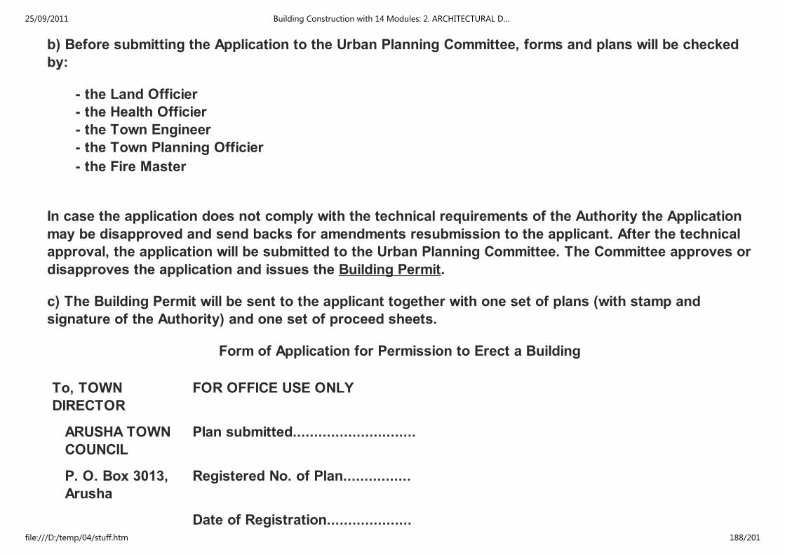
b) Before submitting the Application to the Urban Planning Committee, forms and plans will be checked
by:
- the Land Officier
- the Health Officier
- the Town Engineer
- the Town Planning Officier
- the Fire Master
In case the application does not comply with the technical requirements of the Authority the Application
may be disapproved and send backs for amendments resubmission to the applicant. After the technical
approval, the application will be submitted to the Urban Planning Committee. The Committee approves or
disapproves the application and issues the Building Permit.
c) The Building Permit will be sent to the applicant together with one set of plans (with stamp and
signature of the Authority) and one set of proceed sheets.
Form of Application for Permission to Erect a Building
To, TOWN
DIRECTOR
FOR OFFICE USE ONLY
ARUSHA TOWN
COUNCIL
Plan submitted.............................
P. O. Box 3013,
Arusha
Registered No. of Plan................
Date of Registration....................
25/09/2011 Building Construction with 14 Modules: 2. ARCHITECTURAL D…
file:///D:/temp/04/stuff.htm 188/201
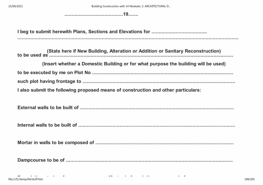
.........................................19.......
I beg to submit herewith Plans, Sections and Elevations for .......................................
...........................................................................................................................................................
(State here if New Building, Alteration or Addition or Sanitary Reconstruction)to be used as .................................................................................................................................
(Insert whether a Domestic Building or for what purpose the building will be used)
to be executed by me on Plot No ...................................................................................................
such plot having frontage to ...........................................................................................................
I also submit the following proposed means of construction and other particulars:
External walls to be built of ............................................................................................................
Internal walls to be built of ..............................................................................................................
Mortar in walls to be composed of .................................................................................................
Dampcourse to be of .....................................................................................................................
Foundations to be of ............................. Mortar in foundation composed of .................................
25/09/2011 Building Construction with 14 Modules: 2. ARCHITECTURAL D…
file:///D:/temp/04/stuff.htm 189/201

Foundations to be of ............................. Mortar in foundation composed of .................................
Roof to be constructed of ...............................................................................................................
Water supply from ..........................................................................................................................
Drainage to sewer/permeable cesspit/impermeable septic/tank (erase words which do not apply). In the
of septic tanks state how the effluent will be disposed of ....................................................
Material of drain pipes ..............................................................................................................
Closet accommodation - (state type)
Indoor
...................................................................................................................................
Outdoor
.................................................................................................................................
Name of Architect or Draughtsman ...............................................................................................
25/09/2011 Building Construction with 14 Modules: 2. ARCHITECTURAL D…
file:///D:/temp/04/stuff.htm 190/201
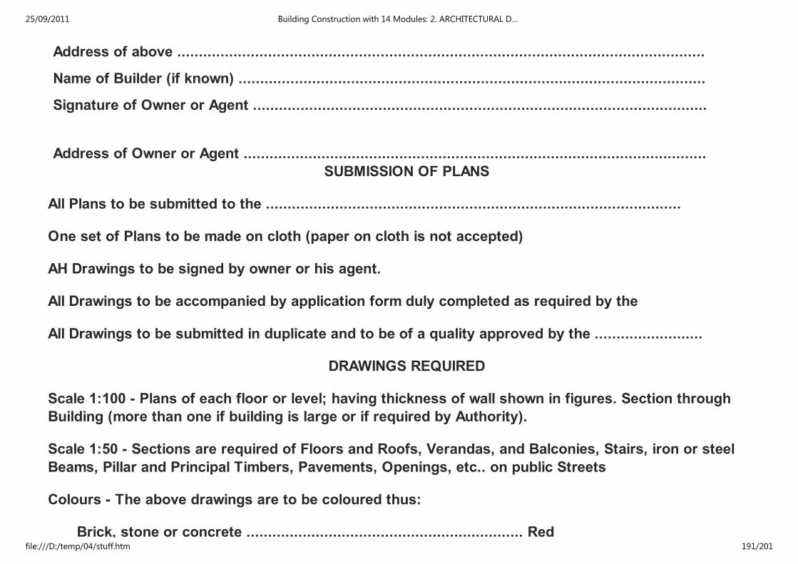
Address of above ..........................................................................................................................
Name of Builder (if known) ............................................................................................................
Signature of Owner or Agent .........................................................................................................
Address of Owner or Agent ...........................................................................................................
SUBMISSION OF PLANS
All Plans to be submitted to the ................................................................................................
One set of Plans to be made on cloth (paper on cloth is not accepted)
AH Drawings to be signed by owner or his agent.
All Drawings to be accompanied by application form duly completed as required by the
All Drawings to be submitted in duplicate and to be of a quality approved by the .........................
DRAWINGS REQUIRED
Scale 1:100 - Plans of each floor or level; having thickness of wall shown in figures. Section through
Building (more than one if building is large or if required by Authority).
Scale 1:50 - Sections are required of Floors and Roofs, Verandas, and Balconies, Stairs, iron or steel
Beams, Pillar and Principal Timbers, Pavements, Openings, etc.. on public Streets
Colours - The above drawings are to be coloured thus:
Brick, stone or concrete ................................................................ Red
25/09/2011 Building Construction with 14 Modules: 2. ARCHITECTURAL D…
file:///D:/temp/04/stuff.htm 191/201
Brick, stone or concrete ................................................................ Red
Fire-proofing, damp-proofing
or impervious floors of stables,
closets, etc. .................................................................................... Thick black line
Work to be removed ...................................................................... Dotted line
Steel or iron ................................................................................... Blue lines, in skeleton
Work existing ................................................................................ Natural Colour
Scale 1:500 - Block plan as follows:
To show plot on which buildings are to be erected.
To show plots immediately adjoining and names of the proprietors thereof.
To show buildings, existing or proposed, on all these plots.
To show numbers of plots, names of streets, and township.
To indicate of what materials existing buildings are composed, i.e. bricks wood and iron, or
stone, etc.
To show lines of drainage, giving size and fall of drains.
To show level and width of the street or streets upon which the proposed buildings will abut
with reference to their ground-floor level.
2.7.2 FORMULARS
25/09/2011 Building Construction with 14 Modules: 2. ARCHITECTURAL D…
file:///D:/temp/04/stuff.htm 192/201

for
office
Date Application
No.
Zone Category FORM A
.............................................................................
APPLICATION FOR PLANNING CONSENT
The Town and Country Planning Ordinance
(All development other then Use classes A (d), A (c) and A (f)
This form should be submitted in duplicate
To: The TOWN DIRECTOR
1. I hereby make application to the .............................................................................. Area
Planning Committee for planning consent to the following development -
.............................................................................................................................................
2. Location and planning zone of proposed development ......................................................
.............................................................................................................................................
3. Development (delete as necessary).
25/09/2011 Building Construction with 14 Modules: 2. ARCHITECTURAL D…
file:///D:/temp/04/stuff.htm 193/201

(a) Category I (Sub division and layout of land)
Number of plots proposed and proposed use of any buildings to be erected thereon
(b) Category II (Change of use of land or premises).
Number of buildings effected (if any) and changes of use proposed
(c) Category III (any building, engineering or mining work in, on under or over any land or
premises)
(d) Previous use: purpose for which building or land was last used
(e) Details of plot or land Area .....................................................................................
acres/sq feet Frontage to road ...............................................................................
feet. Width of street opposite ..................................................................................
feet. Building line or set back adjoining building ....................................................
........................................................................ feet.
4. My interest in land is .....................................................................................................
25/09/2011 Building Construction with 14 Modules: 2. ARCHITECTURAL D…
file:///D:/temp/04/stuff.htm 194/201

5. I enclose three copies of plans illustrating the proposals .............................................
......................................................
Signature of Applicant
Address ....................................................
P.O. Box 3013 ARUSHA TOWN COUNCIL
Phone: 3631/1 TOWN HALL
BUILDING PERMIT
The Township (Building) Rules 1930
Permission is hereby given to ........................................................................................... to erect a
building as a .................................................................................................................................... on
...................................................................................................................................................... in
accordance with the plan (No. ........................................) attached hereto and with all conditions
imposed by the above Rules.
...............................107........... TOWN DIRECTOR
25/09/2011 Building Construction with 14 Modules: 2. ARCHITECTURAL D…
file:///D:/temp/04/stuff.htm 195/201

N. D.: Your attention is invited to the Electricity Rules, 1953, which require you to
notify The Tanganyika Electric Supply Company, Limited, as well as the
Electrical Engineer, General Post Office, before Commencing to erect a
building; should the electric wires in the street be accessible from any
portion of such building where erected or from the scaffolding required
during its construction.
Building Rules 9 (6), This permit is subject to the fulfillment of the covenants entered into between
..................................................................lessee of the above mentioned plot and the Authority,
concerning connection of the building (s) to the main sewerage system when this is applicable.
Building Rule 5 (6), (G. N. 45/1955). The prescribed number of occupants permitted to reside in the
building to which this Permit refers is:
........................................................................................................................................................
........................................................................................................................................................
(Note - Two children may be counted as one adult person)
YOU ARE HEREBY WARNED THAT APPROVAL OF PLANS BY THE
AUTHORITY DOES NOT IMPLY THAT ERECTION OF BUILDINGS IN
ACCORDANCE WITH THESE PLANS WILL NECESSARILY BE IN
ACCORDANCE WITH THE CONDITIONS OF THE RIGHT OF OCCUPANCY
UNDER WHICH YOU HOLD THE LAND
25/09/2011 Building Construction with 14 Modules: 2. ARCHITECTURAL D…
file:///D:/temp/04/stuff.htm 196/201

UNDER WHICH YOU HOLD THE LAND
A
This form MUST be submitted in its proper sequence prior to any further work proceeding.
No. 1885
..............................
..............................
Date.....................................
Plot No. Block No. Area
I hereby give notice that I intend commence the work approved in Plan No. .................................. on
.................................................................... 197 ................
Signed.............................................
TWO DAYS NOTICE REQUIRED
B
This form MUST be submitted in its proper sequence prior to any further work proceeding.
No. 1885
..............................
..............................
Date.....................................
Plot No. Block No. Area
I hereby give notice that the foundation trenches are now ready for inspection.
Plan No. Refers
25/09/2011 Building Construction with 14 Modules: 2. ARCHITECTURAL D…
file:///D:/temp/04/stuff.htm 197/201

Plan No. Refers
Signed.............................................
TWO DAYS NOTICE REQUIRED
C
This form MUST be submitted in its proper sequence prior to any further work proceeding.
No. 1885
..............................
..............................
Date.....................................
Plot No. Block No. Area
I hereby give notice that the foundation concrete in now ready for inspection.
Plan No. Refers
Signed.............................................
TWO DAYS NOTICE REQUIRED
D
This form MUST be submitted in its proper sequence prior to any further work proceeding.
No. 1885
..............................
..............................
Date.....................................
25/09/2011 Building Construction with 14 Modules: 2. ARCHITECTURAL D…
file:///D:/temp/04/stuff.htm 198/201

Plot No. Block No. Area
I hereby give notice that the ground floor concrete and damp proof course are ready for inspection.
Plan No. Refers
Signed.............................................
TWO DAYS NOTICE REQUIRED
E
This form MUST be submitted in its proper sequence prior to any further work proceeding.
No. 1885
..............................
..............................
Date.....................................
Plot No. Block No. Area
I hereby give notice that the work of construction has now proceeded to wall plate level.
Plan No. Refers
Signed.............................................
TWO DAYS NOTICE REQUIRED
F
This form MUST be submitted in its proper sequence prior to any further work proceeding.
No. 1885
.............................. Date.....................................
25/09/2011 Building Construction with 14 Modules: 2. ARCHITECTURAL D…
file:///D:/temp/04/stuff.htm 199/201
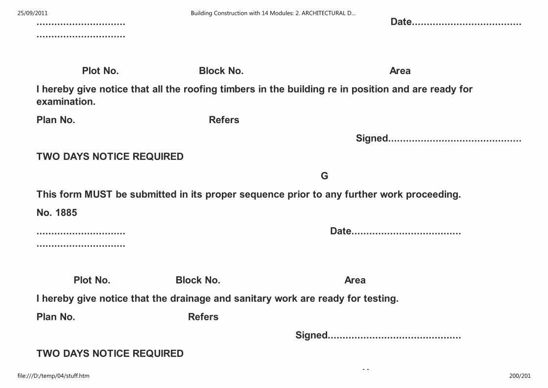
..............................
..............................
Date.....................................
Plot No. Block No. Area
I hereby give notice that all the roofing timbers in the building re in position and are ready for
examination.
Plan No. Refers
Signed.............................................
TWO DAYS NOTICE REQUIRED
G
This form MUST be submitted in its proper sequence prior to any further work proceeding.
No. 1885
..............................
..............................
Date.....................................
Plot No. Block No. Area
I hereby give notice that the drainage and sanitary work are ready for testing.
Plan No. Refers
Signed.............................................
TWO DAYS NOTICE REQUIRED
H
25/09/2011 Building Construction with 14 Modules: 2. ARCHITECTURAL D…
file:///D:/temp/04/stuff.htm 200/201

H
This form MUST be submitted in its proper sequence prior to any further work proceeding.
No. 1885
..............................
..............................
Date.....................................
Plot No. Block No. Area
I hereby give notice that the whole of the work has been completed and I hereby apply for a certificate
of occupation in respect of the premises.
Plan No. Refers
Signed.............................................
SEVEN DAYS NOTICE REQUIRED
Please provide your feedback English | French | Spanish | German
25/09/2011 Building Construction with 14 Modules: 2. ARCHITECTURAL D…
file:///D:/temp/04/stuff.htm 201/201