BRIDGES, CASINGS, AND JOINTS
36
BRIDGES, CASINGS, AND JOINTS OH MY
Transcript of BRIDGES, CASINGS, AND JOINTS

BRIDGES, CASINGS, AND JOINTSOH MY

Roy Mundy, P.E., ENV SP, Assoc. DBIASenior Regional EngineerMcWane [email protected]

Ductile Iron Pipe Joints
Restrained (or not?)

TYTON JOINT®

Spigot
Bell

Mechanical Joint

What Is The Forceat the End
of this 24” Main? 900 psi

TITAN IIrocket??
LadyLiberty!

Restrained JointsThe Design Bible
The Older Method
The Modern Method

No Need To Go
Belt and Suspenders
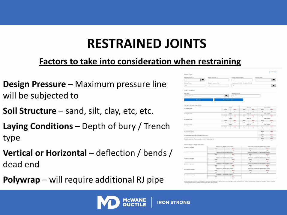
RESTRAINED JOINTS
Design Pressure – Maximum pressure line will be subjected to
Soil Structure – sand, silt, clay, etc, etc.
Laying Conditions – Depth of bury / Trench type
Vertical or Horizontal – deflection / bends / dead end
Polywrap – will require additional RJ pipe
Factors to take into consideration when restraining

American FLEX RING Griffin SNAP LOCK
McWane Ductile TR FLEX

THEN THEREWERE TWO
American FLEX RING
McWane Ductile TR FLEX

RESTRAINED JOINTSTR Flex

Restrained JointsBall & Socket (aka-River Crossing Pipe) Up to 15 degree
Deflection

Restrained JointsSure Stop 350® Gasket
• 3”- 24” Sizes• NSF-61 Approved• UL Listed • FM Approved• 350 psi Rated

Seismic Flex Coupling
• 10.5” of Axial Range• 11.5 degrees joint deflection• Conforms to AWWA C153

GETTING STARTED WITH A BRIDGE CROSSING• Envision –Are we doing the right project?• –Are we doing the project right?• •Bridge Details: will be discussed in further detail later.• –Length• –Radius• –Local Temperatures• –Pipe Location on bridge• –Specific Pipe lengths• –Transition of line from bridge to underground

PIPES YOU COMMONLY SEE• TR Flex vs MJ & Flange pipe• -TR-Flex –more flexible.• -Improved gasket compression.• -Tyton10% compression required –20 to 30% average.• •MJ compression is based on bolt torque.• –TR –readily available.• –TR –Easier to install.• •No bolts / concerns for relaxing bolts –vibration.• -8” Tyton–1 minute to install.• -8” Mj–15 to 30 minutes to install.

Sure Stops on a bridge is like a Beaver on Steroids at a Wood Chopping Convention:

Pipe location will determine the type of hangers required as well as spacing.
• Under the bridge Deck
• Through the Girders
• Side of the bridge
• One top of the bridge

• Supports must support weight of pipe and fluid: • 12” C350 • Gallons per 18’ length = 115 Gal.• 115 Gallons x 8.35 lbs per Gal. = 960 lbs• Pipe weight 35lbs per ft x 18’ = 630 lbs• Total weight = 1,590 lbs• Drilling / Anchoring in concrete –CAUTION
(Anchors are only as good as the connection)

• Supports should be placed as close to the bell on the bell side of the joint.
• May be necessary to provide cut pipe for the bridge crossing:
Example: Niagara Falls840 Feet of 24” pipeDual lineEach piece cut to specific lengthAll lengths marked on face of bellAll pipe joints and hangers matched

PIPES YOU COMMONLY SEE• TR Flex vs MJ & Flange pipe• -TR-Flex –more flexible.• -Improved gasket compression.• -Tyton10% compression required –20 to 30% average.• •MJ compression is based on bolt torque.• –TR –readily available.• –TR –Easier to install.• •No bolts / concerns for relaxing bolts –vibration.• -8” Tyton–1 minute to install.• -8” Mj–15 to 30 minutes to install.
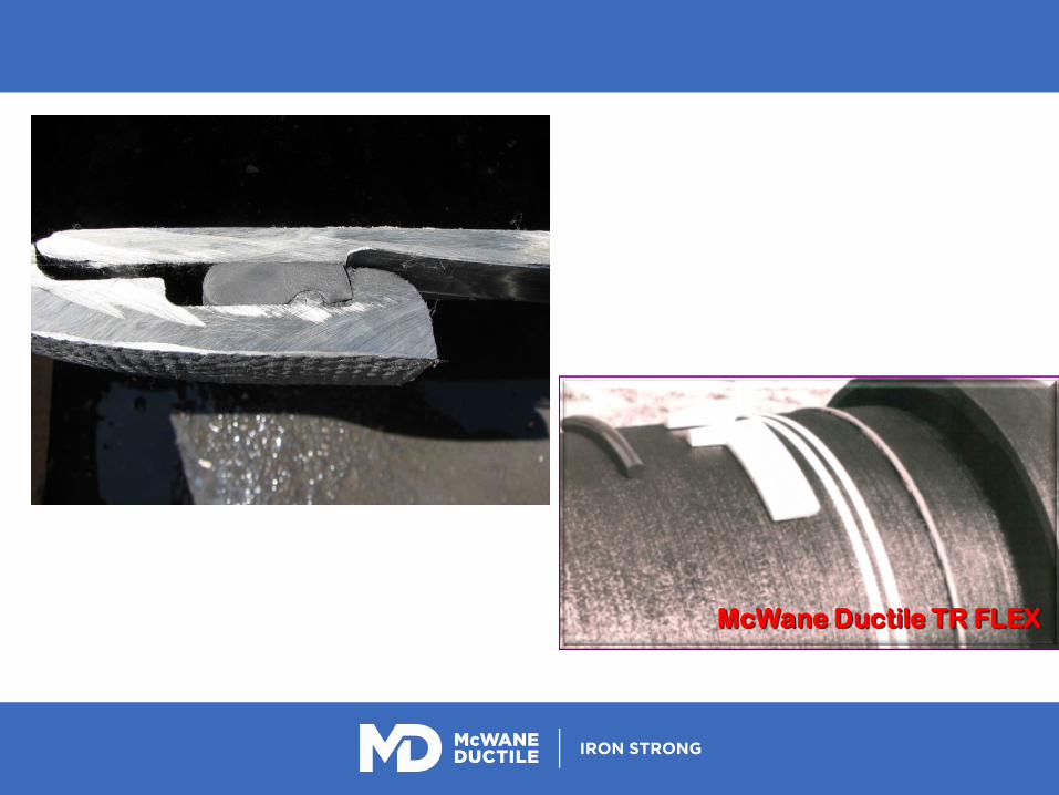
McWane Ductile TR FLEX


HANGERS and SUPPORTS

TRANSITION From
Bridge to Underground
• Casing is often required through Abutment.• –ID of casing / OD of pipe bell.
(OD information: Submittal Sheets. mcwaneductile.com)• •TR vs MJ fittings• –MJ fittings are more common.• –MJ field cuts are common making the transition.• –TR Flex fittings –No thrust blocks required.• •Reduce angles whenever possible.

Other Considerations
• Insulation–regions with freezing temps.• Cable bond connections may be installed for electrical
thawing.(TR Flex® Joint restraint is not adequate for Electrical
Thawing or Cathodic Protection.)• A drain plug may be installed to drain lines which are
not in continuous service.• Air release may be required if the bridge crossing is at a
high point in the system.(Also for pressure testing the bridge section.)

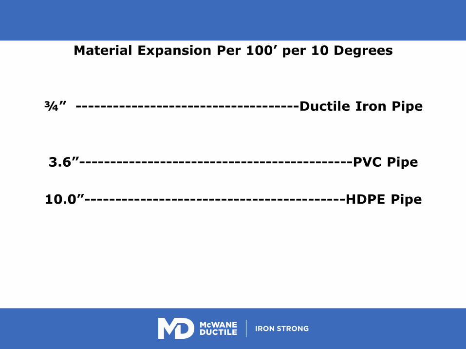
Material Expansion Per 100’ per 10 Degrees
¾” ------------------------------------Ductile Iron Pipe
3.6”--------------------------------------------PVC Pipe
10.0”------------------------------------------HDPE Pipe

QUESTIONS?
Presenter
Presentation Notes
THIS SLIDE CAN BE USED AS A SECTION DIVIDER WITH HEADLINE TYPE OR USED FOR GRAPHICS, CHARTS, IMAGES OR AS A VIDEO BACKGROUND. IT IS MEANT TO BREAK UP A LONGER PRESENTATION OR MAKE INFORMATION STAND OUT FROM THE WHITE CONTENT PAGE.