Management of Half Joints in RTA Bridges - Convention …€¦ · · 2015-02-09Management of Half...
12
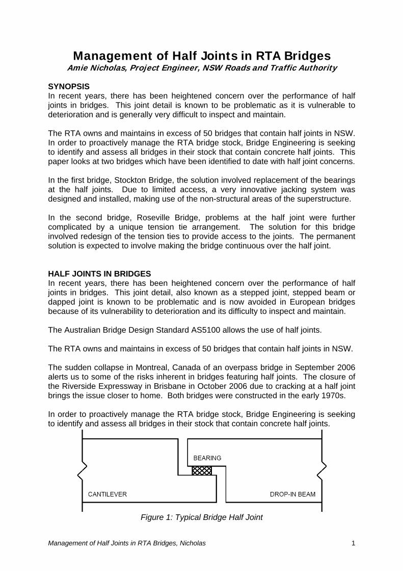
Management of Half Joints in RTA Bridges Amie Nicholas, Project Engineer, NSW Roads and Traffic Authority SYNOPSIS In recent years, there has been heightened concern over the performance of half joints in bridges. This joint detail is known to be problematic as it is vulnerable to deterioration and is generally very difficult to inspect and maintain. The RTA owns and maintains in excess of 50 bridges that contain half joints in NSW. In order to proactively manage the RTA bridge stock, Bridge Engineering is seeking to identify and assess all bridges in their stock that contain concrete half joints. This paper looks at two bridges which have been identified to date with half joint concerns. In the first bridge, Stockton Bridge, the solution involved replacement of the bearings at the half joints. Due to limited access, a very innovative jacking system was designed and installed, making use of the non-structural areas of the superstructure. In the second bridge, Roseville Bridge, problems at the half joint were further complicated by a unique tension tie arrangement. The solution for this bridge involved redesign of the tension ties to provide access to the joints. The permanent solution is expected to involve making the bridge continuous over the half joint. HALF JOINTS IN BRIDGES In recent years, there has been heightened concern over the performance of half joints in bridges. This joint detail, also known as a stepped joint, stepped beam or dapped joint is known to be problematic and is now avoided in European bridges because of its vulnerability to deterioration and its difficulty to inspect and maintain. The Australian Bridge Design Standard AS5100 allows the use of half joints. The RTA owns and maintains in excess of 50 bridges that contain half joints in NSW. The sudden collapse in Montreal, Canada of an overpass bridge in September 2006 alerts us to some of the risks inherent in bridges featuring half joints. The closure of the Riverside Expressway in Brisbane in October 2006 due to cracking at a half joint brings the issue closer to home. Both bridges were constructed in the early 1970s. In order to proactively manage the RTA bridge stock, Bridge Engineering is seeking to identify and assess all bridges in their stock that contain concrete half joints. Figure 1: Typical Bridge Half Joint Management of Half Joints in RTA Bridges, Nicholas 1
Transcript of Management of Half Joints in RTA Bridges - Convention …€¦ · · 2015-02-09Management of Half...
Management of Half Joints in RTA Bridges Amie Nicholas, Project Engineer, NSW Roads and Traffic Authority
SYNOPSIS In recent years, there has been heightened concern over the performance of half joints in bridges. This joint detail is known to be problematic as it is vulnerable to deterioration and is generally very difficult to inspect and maintain. The RTA owns and maintains in excess of 50 bridges that contain half joints in NSW. In order to proactively manage the RTA bridge stock, Bridge Engineering is seeking to identify and assess all bridges in their stock that contain concrete half joints. This paper looks at two bridges which have been identified to date with half joint concerns. In the first bridge, Stockton Bridge, the solution involved replacement of the bearings at the half joints. Due to limited access, a very innovative jacking system was designed and installed, making use of the non-structural areas of the superstructure. In the second bridge, Roseville Bridge, problems at the half joint were further complicated by a unique tension tie arrangement. The solution for this bridge involved redesign of the tension ties to provide access to the joints. The permanent solution is expected to involve making the bridge continuous over the half joint. HALF JOINTS IN BRIDGES In recent years, there has been heightened concern over the performance of half joints in bridges. This joint detail, also known as a stepped joint, stepped beam or dapped joint is known to be problematic and is now avoided in European bridges because of its vulnerability to deterioration and its difficulty to inspect and maintain. The Australian Bridge Design Standard AS5100 allows the use of half joints. The RTA owns and maintains in excess of 50 bridges that contain half joints in NSW. The sudden collapse in Montreal, Canada of an overpass bridge in September 2006 alerts us to some of the risks inherent in bridges featuring half joints. The closure of the Riverside Expressway in Brisbane in October 2006 due to cracking at a half joint brings the issue closer to home. Both bridges were constructed in the early 1970s. In order to proactively manage the RTA bridge stock, Bridge Engineering is seeking to identify and assess all bridges in their stock that contain concrete half joints.
Figure 1: Typical Bridge Half Joint
Management of Half Joints in RTA Bridges, Nicholas 1
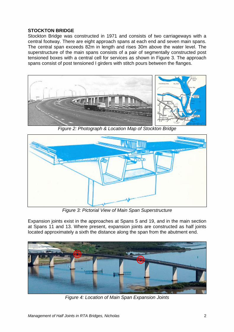
STOCKTON BRIDGE Stockton Bridge was constructed in 1971 and consists of two carriageways with a central footway. There are eight approach spans at each end and seven main spans. The central span exceeds 82m in length and rises 30m above the water level. The superstructure of the main spans consists of a pair of segmentally constructed post tensioned boxes with a central cell for services as shown in Figure 3. The approach spans consist of post tensioned I girders with stitch pours between the flanges.
Figure 2: Photograph & Location Map of Stockton Bridge
Figure 3: Pictorial View of Main Span Superstructure Expansion joints exist in the approaches at Spans 5 and 19, and in the main section at Spans 11 and 13. Where present, expansion joints are constructed as half joints located approximately a sixth the distance along the span from the abutment end.
Figure 4: Location of Main Span Expansion Joints
Management of Half Joints in RTA Bridges, Nicholas 2
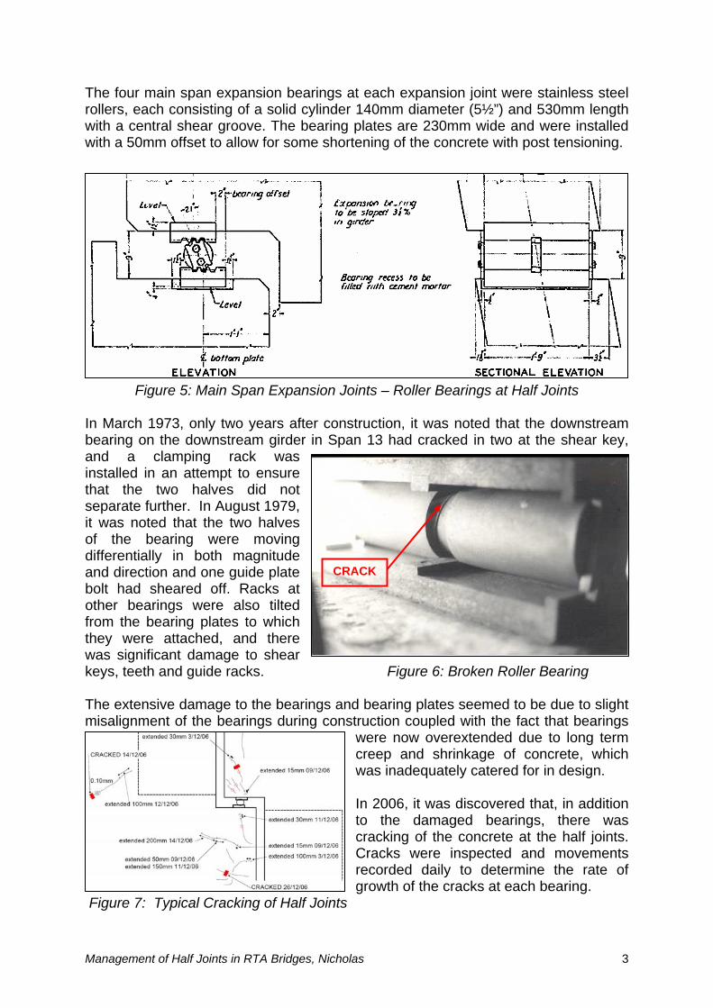
The four main span expansion bearings at each expansion joint were stainless steel rollers, each consisting of a solid cylinder 140mm diameter (5½”) and 530mm length with a central shear groove. The bearing plates are 230mm wide and were installed with a 50mm offset to allow for some shortening of the concrete with post tensioning.
Figure 5: Main Span Expansion Joints – Roller Bearings at Half Joints In March 1973, only two years after construction, it was noted that the downstream bearing on the downstream girder in Span 13 had cracked in two at the shear key, and a clamping rack was installed in an attempt to ensure that the two halves did not separate further. In August 1979, it was noted that the two halves of the bearing were moving differentially in both magnitude and direction and one guide plate bolt had sheared off. Racks at other bearings were also tilted from the bearing plates to which they were attached, and there was significant damage to shear keys, teeth and guide racks. Figure 6: Broken Roller Bearing
CRACK
The extensive damage to the bearings and bearing plates seemed to be due to slight misalignment of the bearings during construction coupled with the fact that bearings
were now overextended due to long term creep and shrinkage of concrete, which was inadequately catered for in design. In 2006, it was discovered that, in addition to the damaged bearings, there was cracking of the concrete at the half joints. Cracks were inspected and movements recorded daily to determine the rate of growth of the cracks at each bearing.
Figure 7: Typical Cracking of Half Joints
Management of Half Joints in RTA Bridges, Nicholas 3
WBM Pty Ltd was engaged by the RTA’s Bridge Evaluation and Assessment Unit to install real time monitoring in December 2006 in order to manage the risk of excessive movement. The instrumentation installed at the half joints monitored vertical and horizontal movements with temperature, and data was downloaded to a website. Any excessive movements would cause SMS alerts to be sent to key people from Bridge Engineering and the Region. Testing of the system was conducted with a semi-trailer and a B-Double to determine movement limits. The RTA engaged Taylor & Herbert Structural Pty Ltd to undertake a detailed analysis of the half joint and to provide a bearing replacement scheme.
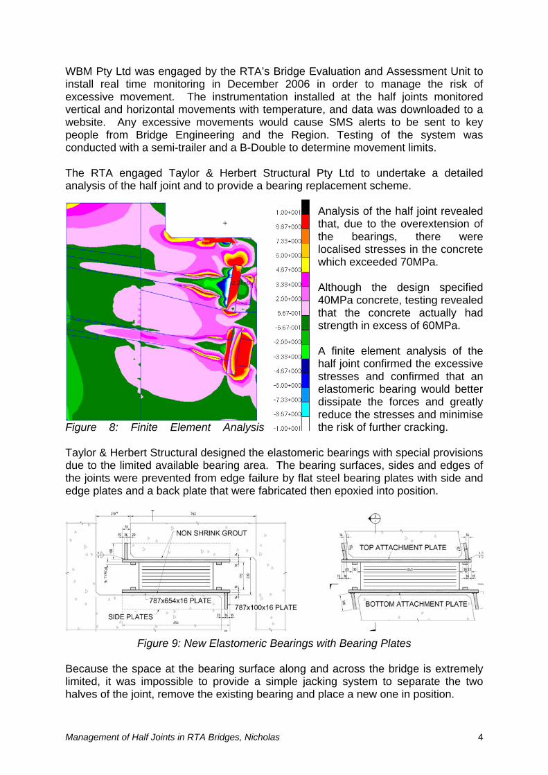
Analysis of the half joint revealed that, due to the overextension of the bearings, there were localised stresses in the concrete which exceeded 70MPa. Although the design specified 40MPa concrete, testing revealed that the concrete actually had strength in excess of 60MPa. A finite element analysis of the
aylor & Herbert Structural designed the elastomeric bearings with special provisions
ecause the space at the bearing surface along and across the bridge is extremely
limited, it was impossible to provide a simple jacking system to separate the two halves of the joint, remove the existing bearing and place a new one in position.
half joint confirmed the excessive stresses and confirmed that an elastomeric bearing would better dissipate the forces and greatly reduce the stresses and minimise
Figure 8: Finite Element Analysis the risk of further cracking.
Tdue to the limited available bearing area. The bearing surfaces, sides and edges of the joints were prevented from edge failure by flat steel bearing plates with side and edge plates and a back plate that were fabricated then epoxied into position.
Figure 9: New Elastomeric Bearings with Bearing Plates
B
Management of Half Joints in RTA Bridges, Nicholas 4
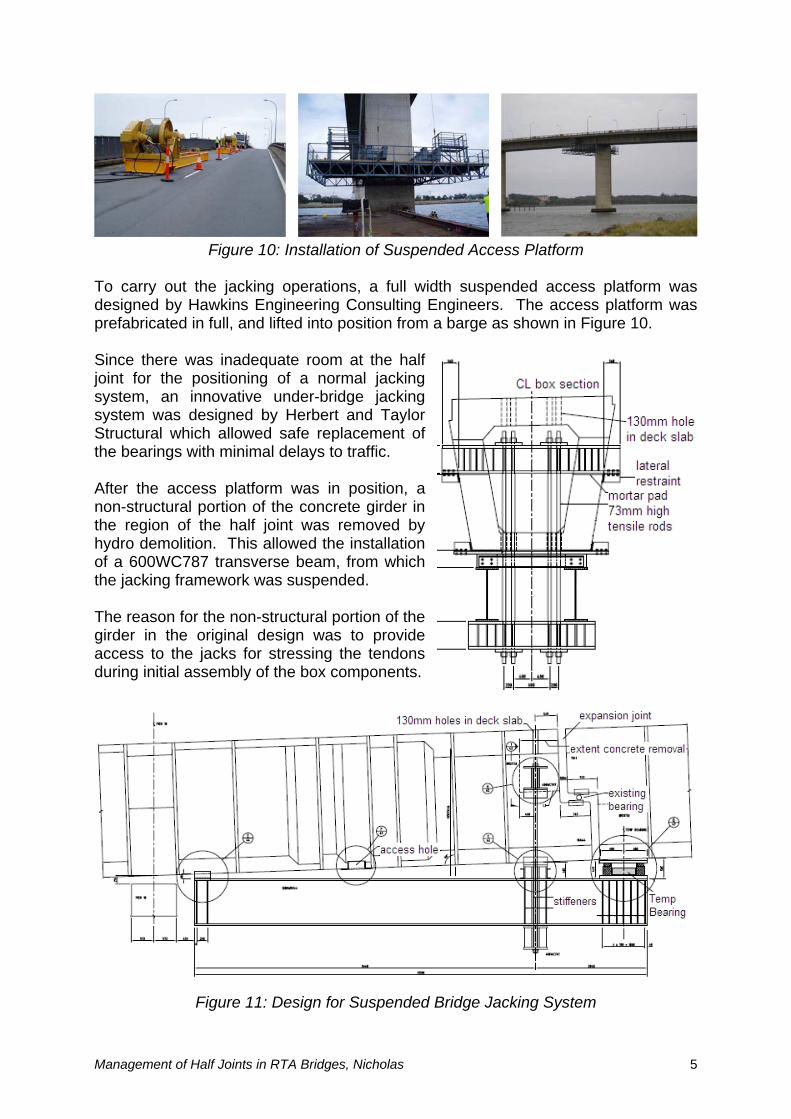
Figure 10: Installation of Suspended Access Platform To carry out the jacking operations, a full width suspended access platform was designed by Ha s platform was refabricated in full, and lifted into position from a barge as shown in Figure 10.
ystem, an innovative under-bridge jacking
r in e region of the half joint was removed by
rovide ccess to the jacks for stressing the tendons
wkins Engineering Consulting Engineers. The accesp Since there was inadequate room at the half joint for the positioning of a normal jacking ssystem was designed by Herbert and Taylor Structural which allowed safe replacement of the bearings with minimal delays to traffic. After the access platform was in position, a non-structural portion of the concrete girdethhydro demolition. This allowed the installation of a 600WC787 transverse beam, from which the jacking framework was suspended. The reason for the non-structural portion of the girder in the original design was to paduring initial assembly of the box components.
Figure 11: Design for Suspended Bridge Jacking System
Management of Half Joints in RTA Bridges, Nicholas 5
From the 600WC transverse beams, four 73mm diameter suspension rods supported 600WC cross beam under the bridge. These in turn supported two 1200WB
jacking beams e side of the
e end of the beams, a temporary elastomeric bearing was placed between the
Pa
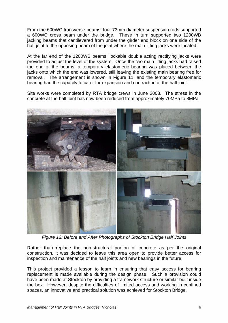
ather than replace the non-structural portion of concrete as per the original constru ss for
spection and maintenance of the half joints and new bearings in the future.
n could ave been made at Stockton by providing a framework structure or similar built inside
a that cantilevered from under the girder end block on on
half joint to the opposing beam of the joint where the main lifting jacks were located. At the far end of the 1200WB beams, lockable double acting rectifying jacks were provided to adjust the level of the system. Once the two main lifting jacks had raisedthjacks onto which the end was lowered, still leaving the existing main bearing free for removal. The arrangement is shown in Figure 11, and the temporary elastomeric bearing had the capacity to cater for expansion and contraction at the half joint. Site works were completed by RTA bridge crews in June 2008. The stress in the concrete at the half joint has now been reduced from approximately 70MPa to 8M
Figure 12: Before and After Photographs of Stockton Bridge Half Joints R
ction, it was decided to leave this area open to provide better accein This project provided a lesson to learn in ensuring that easy access for bearing replacement is made available during the design phase. Such a provisiohthe box. However, despite the difficulties of limited access and working in confined spaces, an innovative and practical solution was achieved for Stockton Bridge.
Management of Half Joints in RTA Bridges, Nicholas 6
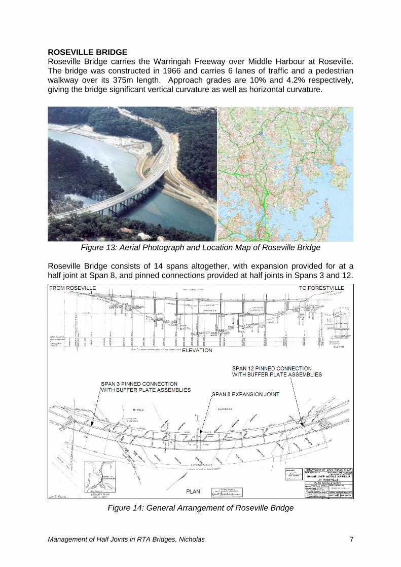
ROSEVILLE BRIDGE Roseville Bridge carries the Warringah Freeway over Middle Harbour at Roseville. The bridge was constructed in 1966 and carries 6 lanes of traffic and a pedestrian
length. Approach grades are 10% and 4.2% respectively,
oseville Bridge consists of 14 spans altogether, with expansion provided for at a half joint and 12.
walkway over its 375mgiving the bridge significant vertical curvature as well as horizontal curvature.
Figure 13: Aerial Photograph and Location Map of Roseville Bridge R
at Span 8, and pinned connections provided at half joints in Spans 3
Figure 14: General Arrangement of Roseville Bridge
Management of Half Joints in RTA Bridges, Nicholas 7
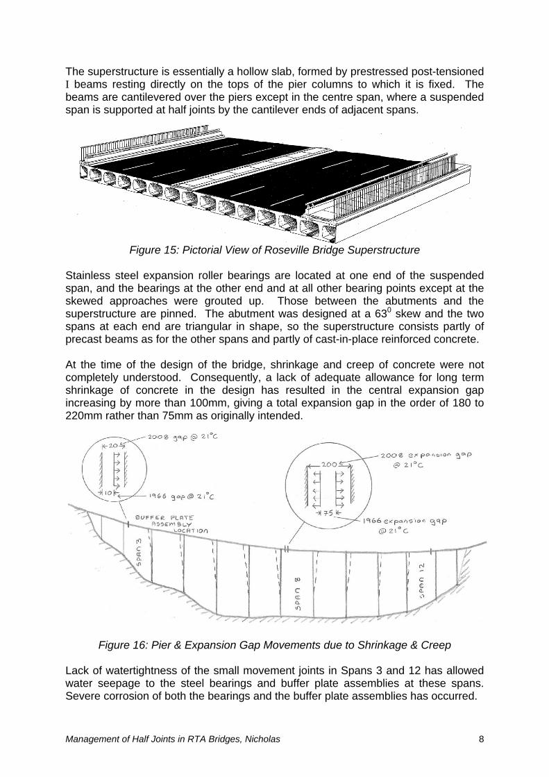
The superstructure is essentially a hollow slab, formed by prestressed post-tensioned er columns to which it is fixed. The
beams are canti e a suspended
tainless steel expansion roller bearings are located at one end of the suspended span, and th xcept at the kewed approaches were grouted up. Those between the abutments and the
hrinkage of concrete in the design has resulted in the central expansion gap
ack of watertightness of the small movement joints in Spans 3 and 12 has allowed water pans.
evere corrosion of both the bearings and the buffer plate assemblies has occurred.
I beams resting directly on the tops of the pilevered over the piers except in the centre span, wher
span is supported at half joints by the cantilever ends of adjacent spans.
Figure 15: Pictorial View of Roseville Bridge Superstructure S
e bearings at the other end and at all other bearing points essuperstructure are pinned. The abutment was designed at a 630 skew and the two spans at each end are triangular in shape, so the superstructure consists partly of precast beams as for the other spans and partly of cast-in-place reinforced concrete. At the time of the design of the bridge, shrinkage and creep of concrete were not completely understood. Consequently, a lack of adequate allowance for long termsincreasing by more than 100mm, giving a total expansion gap in the order of 180 to 220mm rather than 75mm as originally intended.
Figure 16: Pier & Expansion Gap Movements due to Shrinkage & Creep L
seepage to the steel bearings and buffer plate assemblies at these sS
Management of Half Joints in RTA Bridges, Nicholas 8
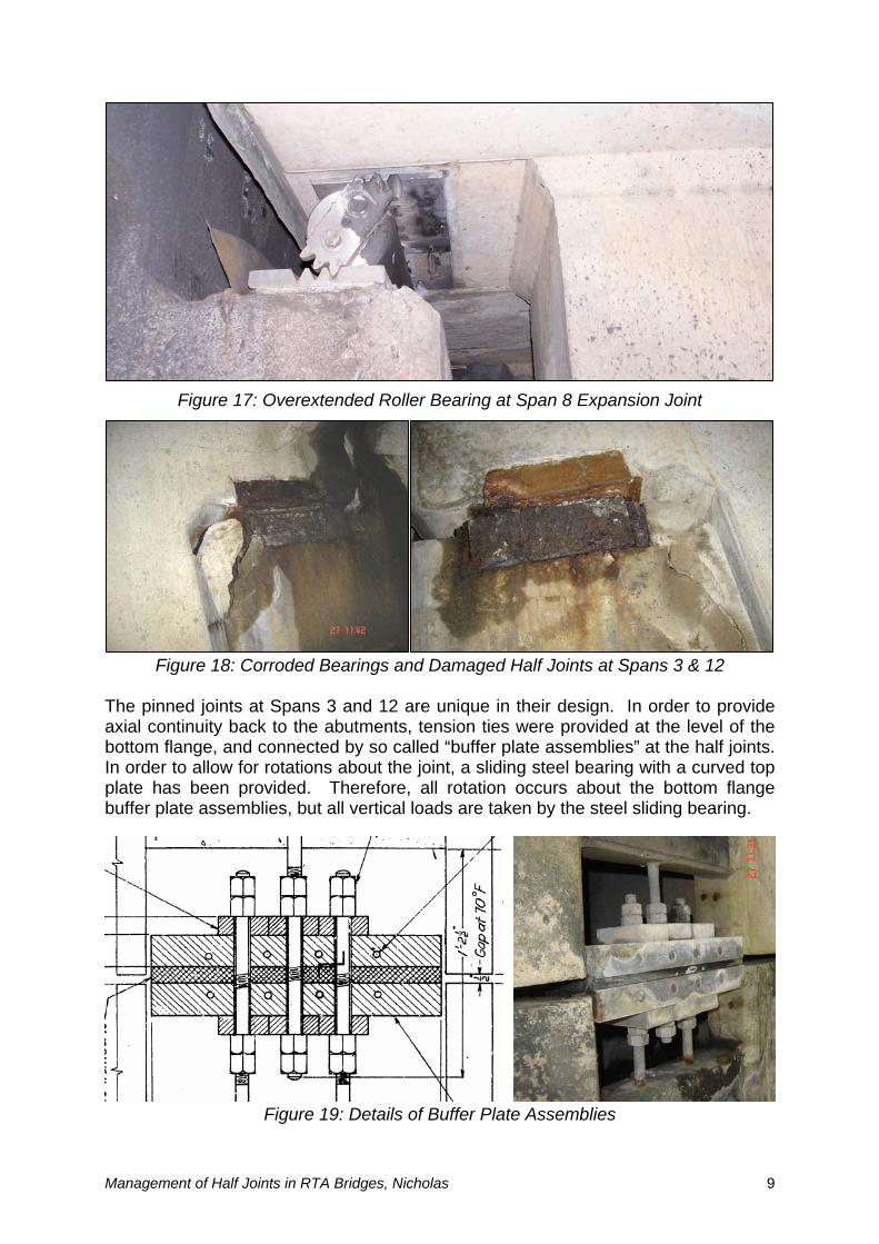
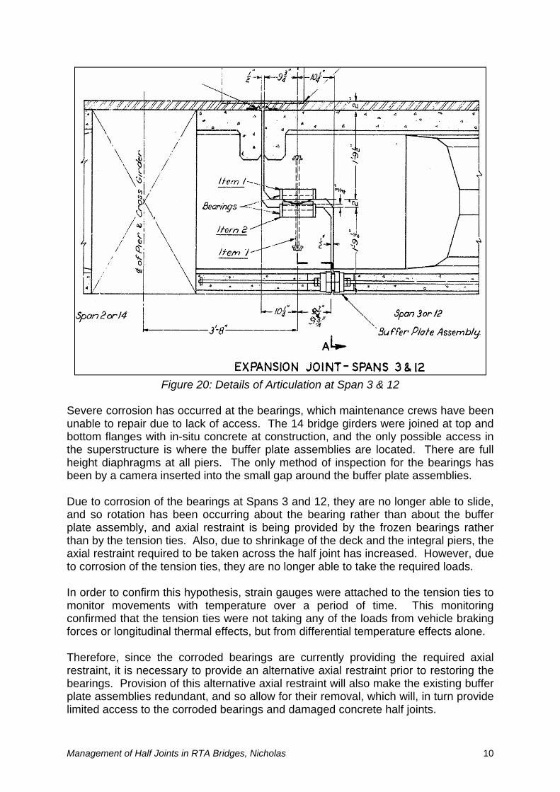
Figure 17: Overextended Roller Bearing at Span 8 Expansion Joint
he pinned joints at Spans 3 and 12 are unique in their design. In order to provide axial c f the ottom flange, and connected by so called “buffer plate assemblies” at the half joints.
Figure 18: Corroded Bearings and Damaged Half Joints at Spans 3 & 12 T
ontinuity back to the abutments, tension ties were provided at the level obIn order to allow for rotations about the joint, a sliding steel bearing with a curved top plate has been provided. Therefore, all rotation occurs about the bottom flange buffer plate assemblies, but all vertical loads are taken by the steel sliding bearing.
Figure 19: Details of Buffer Plate Assemblies
Management of Half Joints in RTA Bridges, Nicholas 9
evere corrosion has occurred at the bearings, which maintenance crews have been unable to repair du joined at top and ottom flanges with in-situ concrete at construction, and the only possible access in
ffer late assembly, and axial restraint is being provided by the frozen bearings rather
ing onfirmed that the tension ties were not taking any of the loads from vehicle braking
earings. Provision of this alternative axial restraint will also make the existing buffer
Figure 20: Details of Articulation at Span 3 & 12 S
e to lack of access. The 14 bridge girders werebthe superstructure is where the buffer plate assemblies are located. There are full height diaphragms at all piers. The only method of inspection for the bearings has been by a camera inserted into the small gap around the buffer plate assemblies. Due to corrosion of the bearings at Spans 3 and 12, they are no longer able to slide, and so rotation has been occurring about the bearing rather than about the bupthan by the tension ties. Also, due to shrinkage of the deck and the integral piers, the axial restraint required to be taken across the half joint has increased. However, due to corrosion of the tension ties, they are no longer able to take the required loads. In order to confirm this hypothesis, strain gauges were attached to the tension ties to monitor movements with temperature over a period of time. This monitorcforces or longitudinal thermal effects, but from differential temperature effects alone. Therefore, since the corroded bearings are currently providing the required axial restraint, it is necessary to provide an alternative axial restraint prior to restoring thebplate assemblies redundant, and so allow for their removal, which will, in turn provide limited access to the corroded bearings and damaged concrete half joints.
Management of Half Joints in RTA Bridges, Nicholas 10
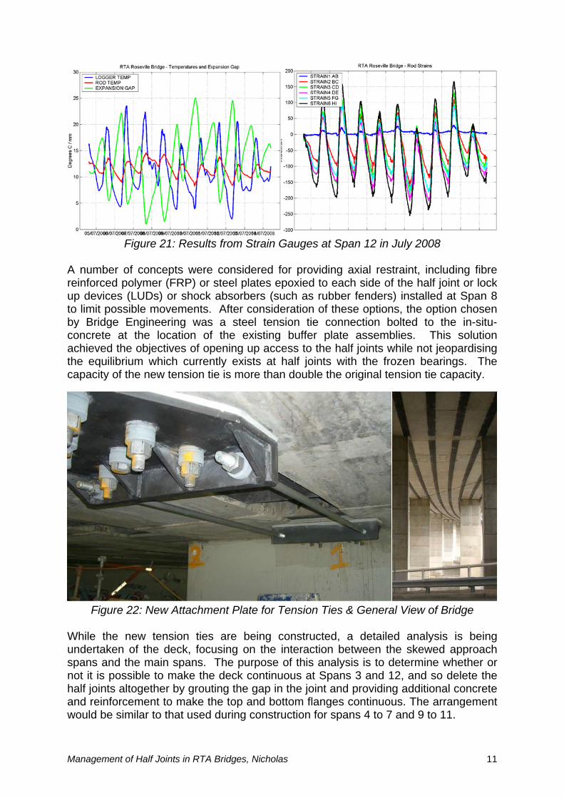
Figure 21: Results from Strain Gauges at Span 12 in July 2008 A number of concepts were considered for providing axial restraint, including fibre reinforced int or lock p devices (LUDs) or shock absorbers (such as rubber fenders) installed at Span 8
While the new tension ties are being constructed, a unde ach pans and the main spans. The purpose of this analysis is to determine whether or
polymer (FRP) or steel plates epoxied to each side of the half jouto limit possible movements. After consideration of these options, the option chosen by Bridge Engineering was a steel tension tie connection bolted to the in-situ-concrete at the location of the existing buffer plate assemblies. This solution achieved the objectives of opening up access to the half joints while not jeopardising the equilibrium which currently exists at half joints with the frozen bearings. The capacity of the new tension tie is more than double the original tension tie capacity.
Figure 22: New Attachment Plate for Tension Ties & General View of Bridge
detailed analysis is being
rtaken of the deck, focusing on the interaction between the skewed approsnot it is possible to make the deck continuous at Spans 3 and 12, and so delete the half joints altogether by grouting the gap in the joint and providing additional concrete and reinforcement to make the top and bottom flanges continuous. The arrangement would be similar to that used during construction for spans 4 to 7 and 9 to 11.
Management of Half Joints in RTA Bridges, Nicholas 11
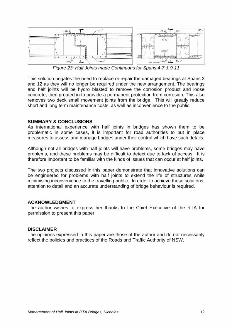
Figure 23: Half Joints made Continuous for Spans 4-7 & 9-11 This solution negates the need to replace or repair the damaged bearings at Spans 3 and 12 as t e bearings nd half joints will be hydro blasted to remove the corrosion product and loose
s international experience with half joints in bridges has shown them to be roblematic in some cases, it is important for road authorities to put in place
bridges under their control which have such details.
erefore important to be familiar with the kinds of issues that can occur at half joints.
inimising inconvenience to the travelling public. In order to achieve these solutions,
he author wishes to express her thanks to the Chief Executive of the RTA for ermission to present this paper.
he opinions expressed in this paper are those of the author and do not necessarily flect the policies and practices of the Roads and Traffic Authority of NSW.
hey will no longer be required under the new arrangement. Thaconcrete, then grouted in to provide a permanent protection from corrosion. This also removes two deck small movement joints from the bridge. This will greatly reduce short and long term maintenance costs, as well as inconvenience to the public. SUMMARY & CONCLUSIONS Apmeasures to assess and manage Although not all bridges with half joints will have problems, some bridges may have problems, and these problems may be difficult to detect due to lack of access. It is th The two projects discussed in this paper demonstrate that innovative solutions can be engineered for problems with half joints to extend the life of structures while mattention to detail and an accurate understanding of bridge behaviour is required. ACKNOWLEDGMENT Tp DISCLAIMER Tre
Management of Half Joints in RTA Bridges, Nicholas 12