Bosch Rexroth AG 1.4 Additonal Accessories Electric Drives ...
7
R911332606-AA_BPZ_DOC 21/10/2010 1/7 "IndraControl L" control 1 Content and Accessories 1.1 Variants This assembly instruction applies to all variants starting with the following type designation code: • CML45.1 … • CML65.1 … • CML85.1 … 1.2 Included Accessories Type Designation Code Parts number Description DOK-CONTRL- ICL45L65L85-IS01- DE-P R911332606 Assembly instruction 1.3 Required Accessories Type Designation Code Parts number Description R-IB IL CML S01 PLSET alternatively: R-IB IL CML S04 PLSE R911299856 R911172193 Connector set (2 input, 2 output and 1 power- connector) for IndraControl L45/L65/L85 1.4 Additonal Accessories Inline terminals, Compact Flash card, function modules, interface cables are listed in the project planning manual or on the internet: www.boschrexroth.com 2 About this Document 2.1 Purpose This assembly instruction explains how to carry out a safe mechanical and electrical installation of IndraControl L45/L65/L85 controls to the technical staff of the machine manufacturer. This document does not constitute the operating manual. 3 Further Documents 4 Safety Instructions IndraControl L45/L65/L85 may only be used with the accessories and add-on components specified in this documentation. Components not expressly listed must neither be assembled nor connected. The same applies to cables and conduits. The products may only be operated with the expressly stated configurations and component combinations as well as with the software and firmware specified in the respective functional description. Read all documents carefully before installing or commissioning the device. Read the safety instructions and all other user notes before operating the device. Bosch Rexroth AG Electric Drives and Controls Bgm.-Dr.-Nebel-Str. 2 97816 Lohr am Main, Germany Phone +49 (0)9352-40-50 60 Fax +49 (0)9352-40-48 85 www.boschrexroth.com Assembly Instruction Rexroth IndraControl L45 Rexroth IndraControl L65 Rexroth IndraControl L85 Title Code Rexroth IndraControl L45/65/85 DOK-CONTRL- ICL45L65L85-PR01-EN-P Project Planning Manual R911332116
Transcript of Bosch Rexroth AG 1.4 Additonal Accessories Electric Drives ...

R911332606-AA_BPZ_DOC 21/10/2010 1/7
"IndraControl L" control
1 Content and Accessories 1.1 Variants
This assembly instruction applies to all variants starting with the following type designation code: • CML45.1 … • CML65.1 … • CML85.1 …
1.2 Included Accessories Type Designation Code Parts number Description DOK-CONTRL-ICL45L65L85-IS01-DE-P
R911332606 Assembly instruction
1.3 Required Accessories Type Designation Code Parts number Description R-IB IL CML S01 PLSET alternatively: R-IB IL CML S04 PLSE
R911299856 R911172193
Connector set (2 input, 2 output and 1 power-connector) for IndraControl L45/L65/L85
1.4 Additonal Accessories
Inline terminals, Compact Flash card, function modules, interface cables are listed in the project planning manual or on the internet: www.boschrexroth.com
2 About this Document 2.1 Purpose
This assembly instruction explains how to carry out a safe mechanical and electrical installation of IndraControl L45/L65/L85 controls to the technical staff of the machine manufacturer. This document does not constitute the operating manual.
3 Further Documents
4 Safety Instructions
IndraControl L45/L65/L85 may only be used with the accessories and add-on components specified in this documentation. Components not expressly listed must neither be assembled nor connected. The same applies to cables and conduits. The products may only be operated with the expressly stated configurations and component combinations as well as with the software and firmware specified in the respective functional description.
Read all documents carefully before installing or commissioning the device. Read the safety instructions and all other user notes before operating the device.
Bosch Rexroth AG Electric Drives and Controls Bgm.-Dr.-Nebel-Str. 2 97816 Lohr am Main, Germany Phone +49 (0)9352-40-50 60 Fax +49 (0)9352-40-48 85 www.boschrexroth.com
Assembly Instruction
Rexroth IndraControl L45 Rexroth IndraControl L65 Rexroth IndraControl L85
Title CodeRexroth IndraControl L45/65/85 DOK-CONTRL-
ICL45L65L85-PR01-EN-P Project Planning Manual R911332116

For more detailed safety notes, refer to the “IndraControl L45/L65/L85” project planning manual, parts number: R911332116.
R911332606-AA_BPZ_DOC 21/10/2010 2/7
5 UL/CSA Certification IndraControl L45/L65/L85 are certified according to • UL508 (Industrial Control
Equipment) and • C22.2 No. 142-M1987 (CSA) However, there can be combinations or stages of expansions with limited or missing certification. Please verify the certification by using the UL label on the device.
To guarantee an UL/CSA-compliant operation, the following conditions have to be fulfilled: • Use only insulated copper wire
suitable for at least 60/75 °C.
6 Technical Data 6.1 Housing Dimensions
Housing dimensions of the IndraControl L45/L65/L85 controls: width: 176 mm, height: 120 mm, depth: 107 mm. Please refer to the following figures for detailed information about the dimensions:
Height of controls with fan: 143 mm
6.2 Top View
6.3 Front View
6.4 Left View
The cut-out for the top-hat rail is arranged centrally
6.5 Front View with Fan
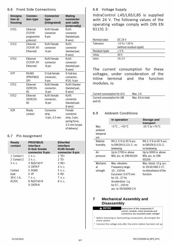
6.6 Front Side Connections
R911332606-AA_BPZ_DOC 21/10/2010 3/7
6.7 Pin Assignment
6.8 Voltage Supply
IndraControl L45/L65/L85 is supplied with 24 V. The following values of the operating voltage comply with DIN EN 61131 2:
Designation at housing
Connec-tion type
Connector type (integrated)
Mating connector and cable (externally)
X7E5 Ethernet (TCP/IP, programming device)
RJ45 female connector 8-pin
RJ45 connector (twisted pair, 8-wire)
X7E3 Ethernet (TCP/IP, RT-Ethernet)
RJ45 female connector 8-pin
RJ45 connector (twisted pair, 8-wire)
Nominal value DC 24 V Tolerance -15 % / +20 %
(without residual ripple) Residual ripple ± 5 % Umax 30 V Umin 19.2 V X7E4 Ethernet
(TCP/IP, RT-Ethernet)
RJ45 female connector 8-pin
RJ45 connector (twisted pair, 8-wire)
X7P RS485 (PROFIBUS DP)
D-Sub female connector,
The current consumption for these voltages, under consideration of the Inline terminal and the function modules, is: Current consumption for ULS Max. 3 A Current consumption for UM and US
Max. 8 A in total
6.9 Ambient Conditions
D-Sub bus connector, IP20, 9-pin 9-pin
X7E1 Ethernet (SERCOS-III)
RJ45 female connector, 8-pin
RJ45-Stecker (twisted pair, 8-wire)
X7E2 Ethernet (SERCOS-III)
RJ45 female connector, 8-pin
RJ45 connector (twisted pair, 8-wire)
X2R Ready Connector strip, 3-pin, 3.5 mm
Female connector strip, 3-pin, spring force, 3.5 mm (scope of delivery)
contact
7 Mechanical Assembly and Disassembly
Ready contact
PROFIBUS interface D-Sub female connector 9-pin
EtherNet interface RJ45 female connector 8-pin
1 Contact 1 2 Contact 2 3 n. c. Contact load: 30 V, 1 A, AC/DC
1 n. c. 2 n. c. 3 RxD/TxD-P 4 CNTR-P 5 DGND 6 VP 7 n. c. 8 RxD/TxD-N 9 CNTR-N
1 TD+ 2 TD- 3 RD+ 4 n. c. 5 n. c. 6 RD- 7 n. c. 8 n. c.
In operation Storage and transport
Max. ambient temperature
+5 °C ... +55 °C -25 °C to +70 °C
Relative humidity
RH-2; 5 % to 95 % acc. to DIN EN 61131-2, no bedewing
RH-2; 5 % to 95 % acc. to DIN EN 61131-2, no bedewing
Air pressure
Up to 2700 m above MSL acc. to DIN 60204
Up to 3000 m above MSL acc. to DIN 60204
Mechanical strength
Max. vibration: Frequency range: 10...150 Hz Excursion: 0.075 mm for 10...57 Hz
Max. shock: 15 g acc. to EN 60 068-2-27, no disturbance of the function
Acceleration: 1 g for 57...150 Hz acc. to EN 60068-2-6

R911332606-AA_BPZ_DOC 21/10/2010 4/7
7.1 Mounting the IndraControl L45/L65/L85
Provide sufficient cooling clearances for the control, see the following illustration:
Mount IndraControl L45/L65/L85 by attaching it onto the top-hat rail from above and then exerting slight pressure to engage the control in the lower section of the housing.
If required, assemble Rexroth Inline terminals in series.
The end plate has to form the mechanical termination to the right of the station, irrespective of whether Rexroth Inline terminals have been mounted in series or not.
Subsequently, place the function modules onto the top-hat rail to the left of IndraControl L45/L65/L85. Slide the function modules along the top-hat rail to the left side of IndraControl L45/L65/L85, until a secure connection is established via the PCIPLUS bus.
Finally, attach end clamps at both sides of the Rexroth control unit. 7.2 Disassembling IndraControl
L45/L65/L85
To disassemble IndraControl L45/L65/ L85, first disconnect the function modules mounted to the left of IndraControl L45/L65/L85. First remove the left-hand end clamp (CLIPFIX) and slide the function modules along the top-hat rail to the
left until the plug connection of the PCIPLUS bus is disconnected.
Subsequently, remove the first Rexroth Inline terminal that is assembled at the right of IndraControl L45/L65/L85. Proceed as follows: 1. Remove the labeling field, if
present. 2. Lever out the connector of the
terminal to be removed by pressing on the rear connector shaft latch. If a terminal is provided with more than one connector, all connectors have to be removed from the terminal.
3. Remove the connector(s).
4. Remove the power connector from IndraControl L45/L65/L85. This ensures that the feathers of the voltage jumpers and the keyway/feather key connection are not damaged. Moreover, the terminal can be accessed more easily.
5. Actuate the release mechanism (1 in the following figure) and remove the terminal perpendicularly to the top-hat rail (2 in the figure).
6. Now, IndraControl L45/L65/L85
can be removed from the top-hat rail by loosening the fixing claw on the bottom side by means of a screwdriver and pulling Indra-
R911332606-AA_BPZ_DOC 21/10/2010 5/7
Control L45/L65/L85 off the top-hat rail, tilting it and removing it by pulling it upwards.
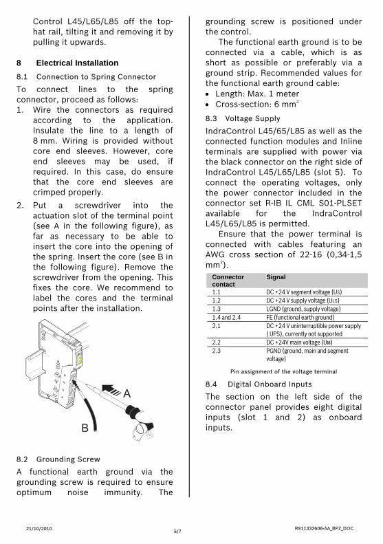
8 Electrical Installation 8.1 Connection to Spring Connector
To connect lines to the spring connector, proceed as follows: 1. Wire the connectors as required
according to the application. Insulate the line to a length of 8 mm. Wiring is provided without core end sleeves. However, core end sleeves may be used, if required. In this case, do ensure that the core end sleeves are crimped properly.
2. Put a screwdriver into the actuation slot of the terminal point (see A in the following figure), as far as necessary to be able to insert the core into the opening of the spring. Insert the core (see B in the following figure). Remove the screwdriver from the opening. This fixes the core. We recommend to label the cores and the terminal points after the installation.
8.2 Grounding Screw
A functional earth ground via the grounding screw is required to ensure optimum noise immunity. The
grounding screw is positioned under the control.
The functional earth ground is to be connected via a cable, which is as short as possible or preferably via a ground strip. Recommended values for the functional earth ground cable: • Length: Max. 1 meter • Cross-section: 6 mm2 8.3 Voltage Supply
IndraControl L45/65/L85 as well as the connected function modules and Inline terminals are supplied with power via the black connector on the right side of IndraControl L45/L65/L85 (slot 5). To connect the operating voltages, only the power connector included in the connector set R-IB IL CML S01-PLSET available for the IndraControl L45/L65/L85 is permitted.
Ensure that the power terminal is connected with cables featuring an AWG cross section of 22-16 (0,34-1,5 mm2).
Pin assignment of the voltage terminal
Connector contact
Signal
1.1 DC +24 V segment voltage (US) 1.2 DC +24 V supply voltage (ULS) 1.3 LGND (ground, supply voltage) 1.4 and 2.4 FE (functional earth ground) 2.1 DC +24 V uninterruptible power supply
( UPS), currently not supported 2.2 DC +24V main voltage (UM) 2.3 PGND (ground, main and segment
voltage)
8.4 Digital Onboard Inputs
The section on the left side of the connector panel provides eight digital inputs (slot 1 and 2) as onboard inputs.

Ensure that the power terminal is connected with cables featuring an AWG cross section of 22-16 (0,34-1,5 mm2).
9 Service and Contact 9.1 Service
The Bosch Rexroth service helpdesk at the Rexroth headquarters in Lohr, Germany, will assist you with all kind of enquiries.
Bosch Rexroth AG Bgm.-Dr.-Nebel-Str.2 97816 Lohr, Germany
Contact:
R911332606-AA_BPZ_DOC 21/10/2010 6/7
Eight digital inputs
• Phone: Mo. - Fr.: 7:00 a.m - 6:00 p.m. CET +49 (0) 9352 40 50 60
8.5 Digital Onboard Outputs
Between the digital inputs and the power terminals, eight digital outputs are arranged on slot 3 and 4. • Fax
+49 (0) 9352 40 49 41 • E-mail:
Eight digital outputs
Outside the helpdesk hours, please contact the German service department directly: • +49 (0) 171 333 88 26 or • +49 (0) 172 660 04 06
Hotline numbers for other countries can be found in the addresses of each region on the internet (see below).
9.2 Addresses
Please find the current addresses of Bosch Rexroth sales offices on the www.boschrexroth.com web site.
8.6 Additional Interfaces
Additional interfaces (EtherNet, PROFIBUS DP, SERCOS III, ready-contact, Flash card, Inline bus and function modules) are described in the Rexroth IndraControl L45/L65/L85 Project Planning Manual, parts number R911332116
On this web site, additional information regarding service, maintenance (e.g. delivery addresses) and training can be found. Outside Germany, please contact the Rexroth sales/service office in your area.

R911332606-AA_BPZ_DOC 21/10/2010 7/7
Notes