BIOREFINE Recycling inorganic chemicals from agro- and bio ... wastes.pdf · inside the pile, the...
74
BIOREFINE Recycling inorganic chemicals from agro- and bio-industrial waste streams Project/Contract number: 320J - Biorefine Document number: BIOREFINE – WP2 – A7 – P1, 2, 5 – D Techniques for nutrient recovery from household and industrial wastes Date: 17/07/2015 Start date of project: 1 May 2011 Duration: 56 months Authors: M. Alonso Camargo-Valero, L. Bamelis, L. De Clercq, F. Delvigne, E. Meers, E. Michels, D. R. Ramirez-Sosa, A. Ross, H. Smeets, C. Tarayre, N. Tarayre, P. T. Williams Authors’ Institutions: DLV InnoVision, Gembloux Agro-Bio Tech, Ghent University, University of Leeds Project funded by the European Regional Development Fund through INTERREG IV B Dissemination Level PU Public x PP Restricted to other programme participants (including the Commission Services) RE Restricted to a group specified by the consortium (including the Commission Services) CO Confidential, only for members of the consortium (including the Commission Services)
Transcript of BIOREFINE Recycling inorganic chemicals from agro- and bio ... wastes.pdf · inside the pile, the...

BIOREFINE
Recycling inorganic chemicals from agro- and bio-industrial
waste streams
Project/Contract number: 320J - Biorefine
Document number: BIOREFINE – WP2 – A7 – P1, 2, 5 – D
Techniques for nutrient recovery from household and industrial wastes
Date: 17/07/2015
Start date of project: 1 May 2011 Duration: 56 months
Authors: M. Alonso Camargo-Valero, L. Bamelis, L. De Clercq, F. Delvigne, E. Meers, E. Michels, D. R.
Ramirez-Sosa, A. Ross, H. Smeets, C. Tarayre, N. Tarayre, P. T. Williams
Authors’ Institutions: DLV InnoVision, Gembloux Agro-Bio Tech, Ghent University, University of Leeds
Project funded by the European Regional Development Fund through INTERREG IV B
Dissemination Level
PU Public x
PP Restricted to other programme participants (including the Commission Services)
RE Restricted to a group specified by the consortium (including the Commission Services)
CO Confidential, only for members of the consortium (including the Commission Services)

Techniques for nutrient recovery from household and industrial wastes
BIOREFINE – WP2 – A5 – P1, 2, 8 – D 2
Table of contents
Table of contents .................................................................................................................................... 2
1 Glossary ........................................................................................................................................... 3
2 Introduction .................................................................................................................................... 6
3 State-of-the-art nutrient recovery techniques from household and industrial wastes ................. 6
3.1 Composting of organic domestic waste .................................................................................. 6
3.2 Composting combined with energy production ................................................................... 13
3.3 Anaerobic digestion – Rainbarrow farm plant ...................................................................... 22
3.4 Anaerobic digestion – Nestlé’s Fawdon factory ................................................................... 25
3.5 Nutrient recovery from landfill leachate .............................................................................. 27
3.6 Phosphorus recovery from sewage sludge: general points .................................................. 28
3.7 Wet chemical treatment of sewage sludge ash .................................................................... 32
3.8 Production of struvite from sewage sludge: PHOSPAQ® process ........................................ 35
3.9 Production of struvite from sewage sludge: OSTARA® process ........................................... 41
3.10 Phosphorus precipitation from industrial wastewater ......................................................... 44
3.11 Production of pellet fertilizer from sewage sludge .............................................................. 46
3.12 Incineration and metal recovery from household and industrial wastes (designed by
SELCHP, UK) ....................................................................................................................................... 49
3.13 Incineration and metal recovery from household and industrial wastes (designed by
LondonWaste) ................................................................................................................................... 54
3.14 Removal of heavy metals from sludge and sediments ........................................................ 57
3.15 Removal of metallic compounds from ashes (IPALLE, Belgium) ........................................... 63
4 List of useful contacts ................................................................................................................... 68
5 Bibliography .................................................................................................................................. 71

Techniques for nutrient recovery from household and industrial wastes
BIOREFINE – WP2 – A5 – P1, 2, 8 – D 3
1 Glossary
AD: Anaerobic Digestion
Al: Aluminium
APC: Air Pollution Control
BTF: Bio Trickling Filter
CaO: Calcium oxide
CH4: Methane
CHP-unit: Combined Heat and Power unit
CO2: Carbon dioxide
CSDU: Centre de Stockage des Déchets Ultimes
C/N ratio: Carbon to nitrogen ratio
DM: Dry Matter
EBPR: Enhanced Biological Phosphorus Removal
Fe: Iron
FeCl3: Iron (III) chloride
GAC: Granule Activated Carbon
HC: Hydrocarbon
hrs: Hours
H2O: Water
H2S: Hydrogen sulfide
kg/d: Kilogram per day
kg/m³.d: Kilogram per cubic meter per day
kg/t: Kilogram per ton
kg CaO/t: Kilogram of calcium oxide per ton
kg K2O/t: Kilogram of potassium oxide per ton
Techniques for nutrient recovery from household and industrial wastes
BIOREFINE – WP2 – A5 – P1, 2, 8 – D 4
kg MgO/t: Kilogram of magnesium oxide per ton
kg N/t: Kilogram of nitrogen per ton
kt P/y: Kiloton of phosphorus per year
kV: Kilovolt
kW: Kilowatt
kWe: Kilowatt electric
kWh: Kilowatt hour
kWh/d: Kilowatt hour per day
m³: Cubic meter
m³/d: Cubic meter per day
m³/h: Cubic meter per hour
MAP: Magnesium Ammonium Phosphate
mbar: Millibar
mg/L: Milligram per liter
mm: Millimeter
MWe: Megawatt electric
MWh/d: Megawatt hour per day
MWth: Megawatt thermal
µm: Micrometer
µS/cm: Micro-siemens per centimeter
N: Nitrogen
NaOH: Sodium hydroxide
Nm³: Normal cubic meter
Nm³/h: Normal cubic meter per hour
N2: Molecular nitrogen

Techniques for nutrient recovery from household and industrial wastes
BIOREFINE – WP2 – A5 – P1, 2, 8 – D 5
P: Phosphorus
Sm³/h: Standard cubic meter per hour
t/y: Ton per year
UASB: Upstream Anaerobic Sludge Blanket
UK: United Kingdom
VFG waste: Vegetable, Fruit and Garden waste
WWTP: Wastewater treatment plant
<: Inferior to

Techniques for nutrient recovery from household and industrial wastes
BIOREFINE – WP2 – A5 – P1, 2, 8 – D 6
2 Introduction
Domestic and industrial waste streams such as wastewater and organic waste contain a lot of
valuable macronutrients (e.g. nitrogen, phosphorus and potassium) and micronutrients (e.g. heavy
metals and rare earth elements). In the past, most of these materials were just landfilled or
discharged, causing environmental damage and losses in nutrients. An advanced system of domestic
waste collection, sorting and recycling has been applied for years in most European countries,
leading to a gradual shift to sustainable resource management. Furthermore, industry is making
efforts to gain a green image and invest in recycling and recovery techniques.
The Interreg IVB project BioRefine aims at facilitating the shift to a circular, bio-based economy in
North Western Europe by using an action-oriented approach consisting in providing applied
technological solutions for improved recycling and recovering of valuable minerals from different
wastestreams. This report gives an overview of the most popular techniques (full-scale or under
development) for nutrient recovery applied to solids and liquids of domestic or industrial origin.
3 State-of-the-art nutrient recovery techniques from household and industrial wastes
Different techniques can be applied to household and industrial wastes. Here, we will consider
different types of wastes, including sewage sludge, leachate from landfills and other organic
materials. Liquid and solid states will be considered.
3.1 Composting of organic domestic waste
3.1.1 General context
The vegetable, fruit and garden (VFG) waste left over by households can be composted on a small
scale at home (the so-called small cycle) or selectively collected and composted on a large scale. The
collection can be organized by inter-municipal waste agencies, as is the case in Belgium, from door-
to-door or at the communal waste recycling depot. Some regions collect both VFG and green waste
(from parks, gardens, nature reserves, roadside verges, etc.) together, others collect them separately
(Vlaco vzw, 2015). Vegetable, fruit and garden (VFG) wastes can also be collected selectively and
used for the production of heat and electricity through anaerobic digestion. From an energetic point
of view, this is the most effective route, since both energy as heat and electricity and a valuable
residual product, digestate, are developed. Digestate can be composted and results in a sufficiently
hygienized product. In Flanders, the quality of the compost obtained is certified by the Flemish
Composting Organization (Vlaco vzw), which means that quality is ensured and so, the compost can
easily be marketed. Besides composting, the digestate can also be processed by mechanical
separation, drying, filtration, etc. as described in the BioRefine report ‘Recovery techniques from
digestate and digestate derivatives’.
Techniques for nutrient recovery from household and industrial wastes
BIOREFINE – WP2 – A5 – P1, 2, 8 – D 7
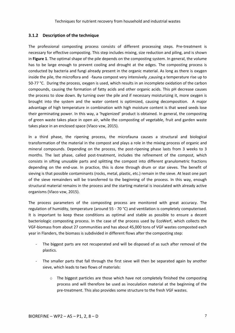
3.1.2 Description of the technique
The professional composting process consists of different processing steps. Pre-treatment is
necessary for effective composting. This step includes mixing, size reduction and piling, and is shown
in Figure 1. The optimal shape of the pile depends on the composting system. In general, the volume
has to be large enough to prevent cooling and drought at the edges. The composting process is
conducted by bacteria and fungi already present in the organic material. As long as there is oxygen
inside the pile, the microflora and -fauna compost very intensively ,causing a temperature rise up to
50-77 °C. During the process, oxygen is used, which results in an incomplete oxidation of the carbon
compounds, causing the formation of fatty acids and other organic acids. This pH decrease causes
the process to slow down. By turning over the pile and if necessary moisturizing it, more oxygen is
brought into the system and the water content is optimized, causing decomposition. A major
advantage of high temperature in combination with high moisture content is that weed seeds lose
their germinating power. In this way, a ‘hygienized’ product is obtained. In general, the composting
of green waste takes place in open air, while the composting of vegetable, fruit and garden waste
takes place in an enclosed space (Vlaco vzw, 2015).
In a third phase, the ripening process, the microfauna causes a structural and biological
transformation of the material in the compost and plays a role in the mixing process of organic and
mineral compounds. Depending on the process, the post-ripening phase lasts from 3 weeks to 3
months. The last phase, called post-treatment, includes the refinement of the compost, which
consists in sifting unusable parts and splitting the compost into different granulometric fractions
depending on the end-use. In practice, this is done through drum or star sieves. The benefit of
sieving is that possible contaminants (rocks, metal, plastic, etc.) remain in the sieve. At least one part
of the sieve remainders will be transferred to the beginning of the process. In this way, enough
structural material remains in the process and the starting material is inoculated with already active
organisms (Vlaco vzw, 2015).
The process parameters of the composting process are monitored with great accuracy. The
regulation of humidity, temperature (around 55 - 70 °C) and ventilation is completely computerised.
It is important to keep these conditions as optimal and stable as possible to ensure a decent
bacteriologic composting process. In the case of the process used by EcoWerf, which collects the
VGF-biomass from about 27 communities and has about 45,000 tons of VGF wastes composted each
year in Flanders, the biomass is subdivided in different flows after the composting step:
- The biggest parts are not recuperated and will be disposed of as such after removal of the
plastics.
- The smaller parts that fall through the first sieve will then be separated again by another
sieve, which leads to two flows of materials:
o The biggest particles are those which have not completely finished the composting
process and will therefore be used as inoculation material at the beginning of the
pre-treatment. This also provides some structure to the fresh VGF wastes.

Techniques for nutrient recovery from household and industrial wastes
BIOREFINE – WP2 – A5 – P1, 2, 8 – D 8
o The smallest particles (size of about and less than 1 mm) are the actual compost. At
this stage, the compost is not ready for use, as it needs some further maturation.
Figure 1: Compost post-treatment.
Source: Vlaco vzw
3.1.3 Unit operations
The case described below is the set-up that is actually implemented at EcoWerf in Vlaams-Brabant
(Belgium).
Reception / Storage volume (A)
The collected VGF will be dumped in this volume straight from the collection vehicle. In Flanders, a
lot of VGF-composting units have developed a separate collection strategy, so there is no direct
interference with other (non-organic) household wastes at this stage.
The presence of the VGF-biomass during this storage step is rather limited in time: in order to obtain
an optimal composting process and prevent rotting and production of odorous gases, it is necessary
to have the biomass treated within short notice (max. 48 hrs). The biomass is taken from these
bunkers with grip arms and placed on belt conveyors for transportation between the different
treatment steps.

Techniques for nutrient recovery from household and industrial wastes
BIOREFINE – WP2 – A5 – P1, 2, 8 – D 9
Rotating sieve (B)
The sieve in the pre-treatment stage will do a first screening of the particles based on their size. A
mesh-size of around 16 mm is usually used. The particles that fall through the sieve (< 16 mm) can
go straight to the composting unit. The bigger particles will have to pass the crusher (see Unit
Operation D) to decrease in size.
Ferro Detector (C)
Throughout the process, there are different places where the metals present in the biomass (e.g.
knives, forks, etc.) are removed. This is done by using a magnet moving above the biomass (without
actually touching it).
Crusher (D)
In the composting process, it is important to have a good surface/volume-ratio. As it is a
microbiological process, the bacteria need the surface to cling to. An increase of the surface-volume
ratio is obtained by crushing the bigger particles at the inlet.
Wooden branches remover (E)
This is a claw-shaped device that removes the branches that fell through the sieve from the biomass.
The wood that is recovered here can be chopped and used as structure material in the composting
unit or to fill the bio-filters for the odour treatment.
Composting (F)
Dependent on the type of biomass that is composted, one can decide between open-air composting
and indoor composting. In the VGF’s composting applications, only indoor composting is in use.
There are different ways to actually implement indoor composting, but the 2 most popular ones are
done either in big halls or in tunnels. EcoWerf’s choice fell on indoor composting. The biomass will
remain for about 5 weeks in the “composting zone” in which it is turned around on a weekly basis so
as to allow “passive” aeration.
In order to obtain a highly effective bacterial activity, it is essential to use optimal process
parameters: the right moisture content, oxygen level and temperature are of the utmost
importance. In order to keep the moisture content at a high level, fluid is sprayed over the
composting material – this can be fresh water, but whenever it is possible, it is the percolate liquid
from the storage of the biomass that is used. The oxygen level is controlled by the ventilation of air
through the biomass. As this ventilation greatly impacts the temperature of the composting
biomass, the type of ventilation will depend on the temperature: if the biomass temperature is too
Techniques for nutrient recovery from household and industrial wastes
BIOREFINE – WP2 – A5 – P1, 2, 8 – D 10
high, outside air will be ventilated through the composting hall. If it is too low, the inside air will be
recirculated and used for aeration.
The air inside the composting hall has about 45°C and relative moisture of 100%. During the process,
there will/can be an accumulation of odour in the air, which makes it necessary for it to be treated
before being discharged to the open air. This is done by a bio-filter system filled with wooden
material that is also collected by EcoWerf.
Plastics removal (G)
After the composting step, the plastic materials are removed by using a wind-shifter that uses the
differences in density to lift out the plastics.
Sieve 1 - composted material (H)
In a first step, the separation of the bigger material from the composted material is achieved. This
material contains too big particles for recirculation and will be disposed of “as such”.
Sieve 2 - composted material (I)
The next step is the separation of the actual compost from the inoculation material. All particles
exceeding 10 to 15 mm in diameter are seen as inoculation material. Inoculation materials are
“compostable” but not yet fully composted – this part of the biomass will be recirculated to the start
of the process where it will be mixed together with the fresh incoming compost.
The smaller particles (< 10 to 15 mm) are considered to be actual compost, and will go through a
maturation phase in order to ensure the stability of the material.
Maturation (J)
The final step of the composting process is the maturation phase, which lasts about 5 weeks. Here,
the composting process slowly goes on in the most resistant parts of the biomass. This can be done
either indoors or outdoors, though it is more common for it to be done in a covered area. The
necessity of turning over the material remains for the sake of aeration. Some additional aeration and
moistening might even be required to ensure the continuation of the process.
The process scheme is shown in Figure 2.

Techniques for nutrient recovery from household and industrial wastes
BIOREFINE – WP2 – A5 – P1, 2, 8 – D 11
3.1.4 Process scheme
Figure 2: Process scheme of compost production.
Source: EcoWerf
Ferro-detector (C)
Reception / storage
volume (A)
Rotating sieve (16 mm)
(B) VGF < 16 mm VGF > 16 mm
Crusher (D) Sieved VGF
Ferro-detector (C)
Wooden branches remover (E)
Composting (F)
Plastic removal (G)
Ferro-detector (C)
Sieve 1 (H) Smaller particles Bigger particles
Sieve 2 (I)
COMPOST
INOCULUM AND
STRUCTURE MATERIAL
Maturation (J)
Organic fraction from household waste
Metal
waste
Plastic
waste
Wood
Biomass
Percolate

Techniques for nutrient recovery from household and industrial wastes
BIOREFINE – WP2 – A5 – P1, 2, 8 – D 12
3.1.5 Characterization of end product
Compost is a stable, hygienized and humus rich end product. It has a high content of stable organic
matter and nutrients which become gradually available for plants. The composition of certified
compost (according to Vlaco vzw) is shown in Table 1.
Table 1: Average composition of Vlaco certified compost obtained from VFG and green wastes.
VFG compost Green compost
Dry matter (kg/ton) 700 600
Organic matter (kg/ton) 250 200
Electroconductivity (µS/cm) 2500 1000
pH-H2O 8 8
Total nitrogen (kg N/ton) 12 7
Total phosphorus (kg P2O5/ton) 7 2.8
Total potassium (kg K2O/ton) 10 6
Total calcium (kg CaO/ton) 23 16
Total magnesium (kg MgO/ton) 5 3
C/N ratio 12 17
Germinative seeds Absent Absent
Pathogens Absent Absent
Source: Vlaco vzw
3.1.6 Useful contact(s) for further information
EcoWerf (Belgium)
Email address: see the website www.ecowerf.be
Vlaco vzw (Belgium)
Email addresses: [email protected], [email protected]

Techniques for nutrient recovery from household and industrial wastes
BIOREFINE – WP2 – A5 – P1, 2, 8 – D 13
3.2 Composting combined with energy production
3.2.1 General description
This second process is very similar to the previous one, but with an additional treatment step in
between. In this case, the production of composting material from VGF waste will be combined with
the production of renewable energy.
The plant that is described below is the plant of Méthavalor (Sydème) in Morsbach (France). This site
has been operational since 2011 and treats about 42,000 tons of waste per year (385,000
inhabitants). About 32,000 tons of that waste consist of VGF waste disposed of by the inhabitants of
surrounding regions, 5,000 tons of organic waste come from restaurants and similar businesses and
the remaining 5,000 tons are green wastes. In the installation, 1 ton of VGF is converted to 100 m3 of
biogas (which corresponds to 70 litres of gasoil) and 200 kg compost.
“Multiflux” sorting
The collection of the waste is slightly different from the traditional collection process: inhabitants
have to put their wastes in plastic bags of different colours. Green bags are meant for biological
waste (VGF), orange bags are for plastics and metals and blue bags are for all other types of
domestic wastes. All these bags are collected simultaneously, which contributes to reducing
collection expenses, since waste is collected only once instead of 3 times.
When all the bags are delivered to the site, they are sorted optically and directed to the sites they
are meant for: the green bags are sent to the biomethane recovering unit, the orange bags are sent
to “recyclable waste” stock (recycling is done on a different site), and the blue bags will be further
treated (landfilled) at the “Centre de Stockage des Déchets Ultimes (CSDU)”.
Preparation of the biodegradable waste
After the separation of the green bags from the other waste, the preparation of the bio-waste for
use in the biogas production starts. As mentioned above, there are several types of bio-wastes that
will be processed in the biogas production: (1) VGF from households (green bags) (2) organic waste
from restaurants, markets, etc. that arrive in bulk (3) green waste and (4) liquid waste (e.g. fats, food
oil). Each type of waste is treated differently:
- VGF from households (in bags)
The first step is the opening of the plastic green bags. Once opened, the contents are spread
on a moving sieve, while the plastic bags are removed by a wind-shifter. This way all the
bags are collected and can be collected. All the material that gets through the sieve will be
directed straight to the intermediate storage unit. The material that is oversized will first go
through a shredder. The materials are also removed by magnets located above the conveyor
belts.

Techniques for nutrient recovery from household and industrial wastes
BIOREFINE – WP2 – A5 – P1, 2, 8 – D 14
- Organic waste (in bulk)
This type of waste is free of plastics as it comes straight from alimentary sources. The
material is guided straight to the shredder system before being sent to the intermediate
storage unit.
- Green waste
This type of waste is also crushed to smaller particles in the shredder.
- Liquid waste
There is no actual pre-treatment of the liquid waste. This type of bio-waste is stored and will
go through the process, in which the different flows and the recycled flow from the
digestate will be mixed together.
Mixing step
At this point, all the above-mentioned flows are mixed together to the actual “feedstock” for the
digester. But before this incoming organic biomass can be converted into biogas in the digesters, it is
important to obtain a feeding mix that meets the process requirements of the digester. To have an
optimal biogas production, several conditions must be fulfilled:
- The incoming biomass (and consequently also the content of the digester) must show an
optimal dry matter (DM) content. This is essential in order to ensure a good mixing and
dynamics within the digester. As this is a “dry digester” type, it can take a higher DM
content, which means that some problems might come up if the material is too dry.
- There must be some inoculation of the “fresh” biomass with a recycle-flow coming from the
digester. This contributes to speeding up the digestion process.
In order to meet these requirements, several precautions have been taken:
- There is a constant flow from the digestate treatment to this mixing point (= recycled flow)
which ensures the inoculation of the fresh material and a lowering of the DM concentration.
Only the liquid part of the digestate (after the separation step) is recycled.
- Also the liquid waste is added in order to lower the DM content. If there is too little liquid
waste to obtain a good DM-content, it is possible to add some fresh water.
From this point, the mixture (= fresh input material + water + recycled flow) is directed to the
digesters.
Digesters
The characteristics of the input material (i.e. a higher DM-content, about 30 to 35 % DM) require the
implementation of a dry digester, which has the advantage of being able to operate with a higher
DM-content: digestate of 25 to 35 % DM against up to 15 % DM in a “wet digester”. The need to add
water is therefore limited in this system.

Techniques for nutrient recovery from household and industrial wastes
BIOREFINE – WP2 – A5 – P1, 2, 8 – D 15
At Méthavalor, there are 3 parallel horizontal digesters. Each digester treats about 15,000 ton/year.
Multi-line work provides optimal flexibility and capacity throughout the year.
Within the digester, the biomass is converted into biogas through the anaerobic process. On
average, a biogas production of 110 to 120 Nm3 per ton of VGF material is achieved. There are
seasonal variations in the biogas-production: in winter, the material coming from households does
not contain garden waste, which generates a higher biogas production. In summer, a bigger fraction
of the incoming VGF is composed of garden waste (grass, weeds, etc.) which have a lower biogas
potential. This difference of composition leads to an overall lower biogas production per ton of VGF.
There are 2 outputs from a digester: biogas and digestate. On the site of Méthavalor, both these
flows are further processed for recovering.
Digestate treatment
The raw digestate coming from the digester is processed in order to separate the l liquid from the
thick fraction. This is done by using a 2-step separation system. Digestate first goes through 3 screw
presses working in parallel. The second step consists in having 2 centrifuges take out as much as DM
as possible from the liquid fraction. This liquid fraction is collected by farmers and applied on land as
a fertilizer. The thick fraction will go through a complete composting process in a tunnel composting
unit. The final compost is sold either in bulk or in small bags.
Biogas valorisation
On the Méthavalor site, there are 2 different ways of recovering biogas: either through a
cogeneration unit or a biogas production one. These two plants are located on the site:
- Cogeneration
Part of the biogas is burned in a cogeneration unit to produce electricity and heat. The
overall electricity production capacity is about 1.7 MWe. This electricity is primarily used to
provide power to all the equipment on the site and the non-consumed electricity is directed
to the grid. The heat produced by this cogeneration unit (about 2 MWth) is used to heat the
digesters. It can also contribute to heating other applications either on the site or elsewhere.
One Nm3 of biogas corresponds to about 2.4 kWe and 2.8 kWth when burnt in a
cogeneration unit.
- Biomethanisation
The part of the biogas that is not burnt in the cogeneration unit will be “upgraded” to a level
similar to the one of natural gas. In order to do this, CO2 and other impurities have to be
removed from the biogas. This purification is achieved in different steps:
o Drying of the biogas (removal of water),
o Purification with active coal (removal of H2S),
o Compressing by increasing the pressure from 16 mbar to 10 bar,
o 2-step Pressure Swing Adsorption (removal of CO2),

Techniques for nutrient recovery from household and industrial wastes
BIOREFINE – WP2 – A5 – P1, 2, 8 – D 16
o Filter (final H2S removal).
The bio-methane that is produced has to be odourised so that people can smell the gas in
case of accidental release into the air. On the Méthavalor site, this bio-methane is used as
fuel. For each Nm3 of biogas that goes into the system, about 0.5 Nm3 of bio-methane is
produced. The CO2 that is separated from the methane will be recycled in the digesters.
3.2.2 Unit operations
“Multiflux” sorting (A)
The “Multiflux” system will ensure the separation of the different types of coloured bags towards
the right treatment system. It is a set of cameras and optical sensors combined with conveyor belts.
There is always an additional “control step”, and in case 2 bags are accidentally misdirected, they
will automatically be returned to the bulk storage.
Bag Opener (B)
All the organic waste coming from households is delivered in plastic bags which are taken to the
ripper head on conveyor belts. The ripper head consists of ripper tines. The ripper head (rotor)
holding the tines rotates in the opposite direction to the flow of material.
Plastic Removal (C)
Plastic (from the bags and similar objects) is removed by a wind-shifter.
Sieve (D)
As with the standard composting process, the particles that go into the system have to be small
enough to ensure good interactions with the bacteria (both in the anaerobic treatment and in the
composting unit.). Therefore, it is important to crush the parts that are too big. Normally, the size of
the particles that go into the system should be less than 16 mm. All the particles that fall through the
sieve go straight to the intermediate storage unit. The bigger parts go through the crusher. In this
case, the sieving device is part of the conveyor belt.
Crusher (E)
Particles the size of which is superior to 16 mm will be crushed to a smaller size.
Ferro Detector (F)
Metals are removed by using big scale magnets that are located around the conveyor belts.

Techniques for nutrient recovery from household and industrial wastes
BIOREFINE – WP2 – A5 – P1, 2, 8 – D 17
Sieve (G)
With a mesh size of 12 to 16 mm, this will subdivide into smaller particles that can be stored in the
intermediate storage unit for further processing and bigger ones that will be sent to the crusher
again.
Intermediate storage (H)
The intermediate storage unit is a place in which all incoming organic flows (except the liquid ones)
can be kept until further treatment. Given the fast decomposition of the material, it is essential (e.g.
for the biogas production) for the retention time in this intermediate storage phase to be as low as
possible.
Mixer (I)
At this point, the feed mix for the digesters is prepared, with a certain level of DM content and
required inoculum. In this step, the mixing of incoming solid organic waste, incoming liquid organic
waste and part of the thin fraction of the digestate is achieved. Water can be added to the mix if
necessary to regulate the water content.
Digester (J)
Three dry digesters (type Kompogas) are used. These reactors are all plug-flow digesters that work
non-stop, which makes it more convenient to manage both the manpower involved and the
downstream located biogas-recovering equipment. The retention time of the organic material varies
from 14 to 20 days. A low-speed agitator prevents the sedimentation of dense media materials and
will take the material to the exit of the digester. The temperature inside the digesters is 50 – 55 °C,
which corresponds to thermophilic conditions. The advantages of this higher temperature
(compared to the one measured in mesophilic reactors) is that the conversion and digestion process
occurs faster and that the material is free of spores, germs and micro-organisms after passing
through the digester. On the other hand, the system is more sensitive to calamities and instabilities,
which means that a closer monitoring of the system is required.
First separation (K)
A first division of the digestate is done with 3 screw presses. In this process, about 25 – 40 % of the
DM are removed from the digestate. The thick fraction is sent to composting whereas the thin
fraction will be further treated. It is important to note that, at this point of the process, there is a lot
of odour production due to the loss of pressure and therefore a release of ammonia. This factor
must be taken into account for the set-up of a similar plant, as this will require an adequate odour
treatment system.

Techniques for nutrient recovery from household and industrial wastes
BIOREFINE – WP2 – A5 – P1, 2, 8 – D 18
Second separation (L)
In the second separation step, the DM that remained in the liquid fraction coming from the screw
presses will be further removed. As in this phase the DM-removal effectiveness needs to be higher, 2
parallel centrifuges have been installed. The removal potential of a centrifuge is normally about 75 %
of the DM.
Composting (M)
The thick fraction coming from the screw presses and the centrifuges will be further composted. This
is done in the same way as in the stages described before. The fully matured compost is sold in bulk
or in bags.
Cogeneration unit (N)
Part of the biogas produced in the digester is transformed into heat and electricity in a cogeneration
unit or in a combined heat and power plant (CHP unit). The total capacity of Méthavalor is 1.7 MWe.
The heat produced is used to heat the digesters and other equipment or even buildings in the
district. The heat produced by a CHP unit is available at different levels: the higher temperature level
corresponds to the heat coming from the exhaust gases of the engine. The temperature of these
exhaust gases at the outlet of the engine varies from 400 to 450 °C. About 20 – 25 % of the incoming
energy is converted into heat. The lower temperature results from the heat coming from the cooling
water from the engine. This heat is available at 55 or 90 °C. As this second type of heat is part of the
cooling system, the cooling away of this heat is crucial for the smooth running of the CHP-engine. In
case the heat is not consumed, it will be cooled away in air-coolers. About 20 – 25 % of the incoming
energy is converted into this lower level heat. The power is used all over the plant – the remaining
part is sent to the electricity grid. About 40-45 % of the energy generated by biogas is converted into
electricity in the CHP-unit. Working with 2 CHP-engines (700 kWe and 1000 kWe) has the advantage
that in case of maintenance of one of the devices, the other one can ensure enough energy
production to keep the plant running.
Drying (O)
The biogas that is not burned in the CHP unit will be dried in order to remove the water it contains.
This is done by cooling, leading to water condensation. After that, the condensed water is removed
and the biogas is heated up again.
Active Coal (P)
Active coal is used to remove different kinds of impurities from biogas, among which H2S, siloxanes
and other volatile organic compounds.

Techniques for nutrient recovery from household and industrial wastes
BIOREFINE – WP2 – A5 – P1, 2, 8 – D 19
Compressor (Q)
The pressure in the digesters is only 16 mbar, which is not sufficient to pass the complete processing
unit and to obtain actual bio-methane. In this process, a pressure of about 10 bar is required. The
rise (in pressure) from 16 mbar to 10 bar is obtained with the help of a biogas compressor.
Pressure Swing Adsorption (PSA) (R)
Pressure Swing Adsorption (PSA) is a dry method used to separate gases thanks to physical
properties. The raw biogas is compressed and fed into an adsorption column. In this column, CO2
(carbon dioxide) is retained but methane (CH4) is not. If the column is saturated with CO2, the
pressure is released and the CO2 will be desorbed and led into an off-gas stream. In order to be able
to work in a continuous mode, it is important to work with multiple columns in parallel, which will
alternately be closed and opened. The Méthavalor PSA-installation has a capacity of about 100
Nm3/h (input biogas flow).
Filtration (S)
Just before the biogas can be turned into engine fuel, a removal of all remaining impurities is
necessary.
Odourisation (T)
Methane (CH4) as such is odourless and cannot be smelled by humans. Therefore, in order to
prevent unnoticed accidental releases, the bio-methane can be made detectable thanks to
odourising agents.
The treatment is presented in Figures 3 and 4.

Techniques for nutrient recovery from household and industrial wastes
BIOREFINE – WP2 – A5 – P1, 2, 8 – D 20
3.2.3 Process scheme
Figure 3: Process scheme of Méthavalor (part 1).
Source: Sydeme-Méthavalor

Techniques for nutrient recovery from household and industrial wastes
BIOREFINE – WP2 – A5 – P1, 2, 8 – D 21
Figure 4: Process scheme of Méthavalor (part 2).
Source: Sydeme-Méthavalor
3.2.4 Additional comments
The overall investment cost of the Méthavalor site is significant (about 40,000,000 €). Nevertheless,
the operating company would like to extend the amount of digesters and to increase the capacity of
the plant.

Techniques for nutrient recovery from household and industrial wastes
BIOREFINE – WP2 – A5 – P1, 2, 8 – D 22
3.2.5 Useful contact(s) for further information
DLV Innovision (Belgium)
Email address: [email protected]
Sydeme-Méthavalor (France)
Email address: see website www.sydeme.fr/site/equip_methanisation1.php
3.3 Anaerobic digestion – Rainbarrow farm plant
3.3.1 General description
In 2012, the first commercial anaerobic digestion process generating biomethane connected to Grid
Plant in England was started at Rainbarrow farm, in Cornwall. The anaerobic digester at Rainbarrow
farm is fed with maize, grass, potato waste, whey and small amounts of food waste (chocolate and
muesli) from local factories. The plant uses around 41,000 tons of maize grass and potato waste
from local farmers as well as organic waste (e.g. chicken manure) from local farms and factories such
as Dorset Cereals and the House of Dorchester Chocolate Factory (Lermen, 2013).
About 850 standard cubic metres/hour (Sm³/h) of biogas production can be achieved in the
Rainbarrow plant. The gas produced (with approximately 53 % CH4) is shared between the energy
generator and the biogas upgrading system (gas grid injection). About 200 Sm³/h of biogas is used to
fuel a 400 kW generator. Around 50 % of the generated energy is used on site to supply the
installation and the rest is exported.
Up to 650 Sm³/h of biogas is led to the DMT Carborex® MS biogas upgrading plant, which cleans out
the CO2 from the gas stream with a multistage system of membranes so as to reach a gas with a
content of 98.4 % CH4. Before entering the gas networks, biomethane gets into the Net Entry Facility
(NEF unit) where about 4 % propane is added to increase the biogas potential. At this stage, a
specific gas odour is also added to the biomethane in order to match the quality of natural gas. The
biomethane flow produced in Rainbarrow is around 400 Sm3/h which is enough to provide gas for
4,000 houses in winter. Moreover, the plant produces 8,000 tons/year of digestate which can be
used as a fertiliser (Langerak, 2013).
3.3.2 Unit operations
The Rainbarrow multi-stage system makes use of highly selective membranes making it possible to
optimize methane production (98% CH4), reduce propane addition and obtain pure CO2 (>99.5 %
pure). It is the only upgrading technology that also removes significant amounts of oxygen (up to 70
%) (Langerak, 2013).

Techniques for nutrient recovery from household and industrial wastes
BIOREFINE – WP2 – A5 – P1, 2, 8 – D 23
After anaerobic digestion, the gas produced goes over to the upgrading plant where
desulphurisation, removal of carbon dioxide and dehumidification are done (Dirkse, 2015).
Biogas compression
The incoming biogas is compressed to 8-10 bar. Since biogas usually contains small amounts of
hydrogen sulphide, an oil-free compressor is needed. The compressed biogas is cooled with water
obtained via a cooling system.
Removal of carbon dioxide and hydrogen sulphide
After the cooling phase, carbon dioxide and hydrogen sulphide are removed in a scrubber. The
scrubber is designed for mass and heat transfer. The gases are absorbed together with the water at
a low and constant temperature. The recirculation water is fed into the absorber at the top, while
the biogas flows through the absorber in the opposite direction. They come into contact in the
absorber and the carbon dioxide and hydrogen sulphide in the biogas are reduced. Carbon dioxide
and hydrogen sulphide dissolve better than methane in water. Some methane will also be absorbed,
but this can be recycled in the gas-freeing phases.
Gasses’ removal from circulation water
Used circulation water with dissolved gases goes through a flash vessel at a 2-bar pressure in order
to reduce the methane losses. The water is partly degased and the gas from the flash tank is
recirculated to the inlet of the upgrading plant. The gas inside the multi-stage membrane system
separates CO2 from CH4 thanks to different permeation rates. The methane losses are controlled by
adjustments of the pressure in the flash tank.
The recirculation water out of the absorber is recycled by gas freeing in three steps.
- The recovered gas stream, with CO2, H2S and CH4 goes through the various pressure stages
for methane separation. In the meantime, the recirculation water coming from the absorber
is recycled by freeing gas, while water pressure is reduced from 10 to 2-4 bar so as to release
more gases. The gas recovered then goes through the pressure stages.
- The gas resulting from the lowest gas-freeing circuit with high concentration in CO2 either
goes through the pressure stages again or is used as industrial raw gas.
- The recirculation water coming from the methane recovery tower is sent into an air-
stripping unit in order to release CO2 and H2S. In the air-stripping tower, the air coming from
outside is blown into a desorption tower where the recirculation water flows down the
other way. Most of the CO2 and H2S is removed by stripping. The treated recirculation water
is pumped back to the absorber. The air coming from the air-stripping unit is sent to a Bio
Trickling Filter (BTF) in order to reduce H2S contamination biologically. The BTF is a biological
filter for the treatment of wastewater and air and consists of a cylindrical tank filled with

Techniques for nutrient recovery from household and industrial wastes
BIOREFINE – WP2 – A5 – P1, 2, 8 – D 24
plastic materials which act as biofilm carriers. The wastewater is fed into the filler at the top,
whilst the air flows through the filter. Intensive mixing takes place in the filter and the
contaminations in the air and water are reduced by the biofilm.
Biogas drying
An absorption dryer is installed behind the water absorption column to extract water from the
upgraded biogas. The dryer is self-regenerating and consists of two columns containing a drying
agent. The post-absorption upgraded biogas is dried and polished prior to delivery to the gas grid by
vessels filled with a drying agent and activated carbon. The drying vessels self-regenerate by guiding
approx. 5-10 % of the dried gas through the regenerating column.
Biogas purification
Before the dried gas is led into the column, it goes through a heat exchanger. The regeneration
pressure is approximately 200 mbar, which means that the gas is quite fit to absorb the water in the
drying agent. Granular Activated Carbon (GAC) vessels purify the upgraded biogas from H2S,
siloxanes and traces of HC. In order to optimize the process, CO2, CH4, H2O and H2S are measured
continuously. A programmable system controls the process according to the gas analyses results.
The scheme of the process is shown in Figure 5.

Techniques for nutrient recovery from household and industrial wastes
BIOREFINE – WP2 – A5 – P1, 2, 8 – D 25
3.3.3 Process scheme
Figure 5: Process scheme of the DMT Carborex MS system.
Source: Lems R. and Dirkse E.H.M., (2010)
3.3.4 Useful contact(s) for further information
University of Leeds (United Kingdom)
Email addresses: [email protected], [email protected]
3.4 Anaerobic digestion – Nestlé’s Fawdon factory
3.4.1 General description
Nestlé’s Fawdon factory is one of the UK’s main confectionery production sites. The former
Rowntree factory (Nestlé's second largest UK site) produces a range of confectionery brands.
Fawdon factory set off an anaerobic digestion plant for the treatment of its wastewater. This plant is
part of an initiative aiming at reducing the carbon footprint from the factory, and was started in
August 2013 with a production of 300 kWe.
The anaerobic digestion plant treats liquid effluents, reject, confectionery and residual ingredients
(mainly fed to pigs). By digesting these materials the plant is able to supply renewable energy to the
factory, reducing disposal and power costs.

Techniques for nutrient recovery from household and industrial wastes
BIOREFINE – WP2 – A5 – P1, 2, 8 – D 26
3.4.2 Unit operations
Nestlé’s liquid AD facility uses a wide range of techniques developed by Clearfleau (see Erreur !
Source du renvoi introuvable.), including several steps.
Feedstock supply
Two tanks balance variable flows. Solid residues are dissolved into the effluent before being fed into
the reactor.
Anaerobic Reactor
A 1,500 m3 tank is fed with 275 m3/d of mixed feedstock. A separator returns degradable solids to
the outside mixing digester.
Biogas Handling
The biogas generated in the digester and stored in the gas dome is cleaned prior to burning in the
CHP located alongside the AD plant. At present, most AD plants produce renewable electricity from
Combined Heat and Power (CHP) engines along with surplus heat. The electricity generated can be
used on site (to replace bought-in power) or sold to the national power grid.
Process Control
In the middle of the plant, the control system includes simulation tools of all the key elements of the
process linked to the site’s supervisory control and data acquisition system.
The project is beginning to lower the site’s CO2 emissions and helping to control energy costs. It is
part of an investment programme aiming at noticeably reducing its environmental footprint and
enhancing sustainable production (Clearfleau, 2015; Gueterbock, 2014a; Gueterbock, 2014b;
Clearfleau, 2013). The process scheme is shown in Figure 6.

Techniques for nutrient recovery from household and industrial wastes
BIOREFINE – WP2 – A5 – P1, 2, 8 – D 27
3.4.3 Process scheme
Figure 6: Nestlé’s Fawdon Anaerobic Digestion Process.
Source: Gueterbock R., (2014 a)
3.4.4 Useful contact(s) for further information
University of Leeds (United Kingdom)
Email addresses: [email protected], [email protected]
3.5 Nutrient recovery from landfill leachate
Municipal landfill leachate results from the percolation of rainwater through solid waste and is seen
as a wastewater type with one of the greatest environmental impacts because of high
concentrations of ammonium, salts and organic matter. The conventional nitrification–
denitrification is not very suitable for leachate treatment. Since the level of ammonia is high, high
hydraulic residence times (and thus large reaction volumes) are required to reduce the toxicity
coming from ammonia.
Recent investigations have shown that ammonium can be recovered from landfill leachate by
struvite, magnesium ammonium phosphate (MAP) and precipitation (Oloibiri, 2013). The limitation
of this way of recovering is that an external source of magnesium and phosphate is needed given the
fact that landfill leachate is deficient in magnesium and phosphorus. Li and Zhao (2001) obtained a

Techniques for nutrient recovery from household and industrial wastes
BIOREFINE – WP2 – A5 – P1, 2, 8 – D 28
reduction of the ammonium concentration in ammonium rich landfill leachate from 5,600 mg/L to
110 mg/L through struvite precipitation at a pH of 8.5 to 9.0. Results from Di Iaconi et al. (2010)
showed that 95 % ammonium removal was achieved with a Mg:NH4:PO4 ratio of 2:1:1, at pH 9.
Similar studies confirmed that ammonium removal efficiencies of up to 90% can be achieved by
struvite precipitation, involving addition of a magnesium and phosphorus source followed by pH
adjustment (Kim et al., 2007). Struvite precipitation from landfill leachate is a technique under
investigation and is not yet subject to full-scale implementation.
3.6 Phosphorus recovery from sewage sludge: general ities
3.6.1 Potentialities of sewage sludge in the United Kingdom: a case study
Phosphorus (P) is a nutrient indispensable to the growth of plants and the production of food.
Modern agriculture uses mineral fertilizers which are derived from phosphate rock and need to be
applied regularly to stimulate production. Since phosphate rocks are non-renewable, there is
growing concern over a lack of phosphorus and subsequent sustainability of agriculture and food
security (Cooper and Carliell-Marquet, 2013).
Cordell et al. (2009) reported that phosphate rock reserves are decreasing more and more in
addition to being located in few countries (Morocco, China, USA and Western Sahara). The discharge
of treated or untreated wastewater into bodies of water with high nitrogen and phosphorus
concentrations has also caused eutrophication. Owing to this, it is necessary to recover P from waste
streams and reuse it to various purposes.
Since the UK relies on imported phosphorus, it is crucial to optimize its use and find out ways of
recovering it most effectively. Figure 7 shows the imports and exports of phosphorus in the UK in
2009 (Cooper and Carliell-Marquet, 2013).

Techniques for nutrient recovery from household and industrial wastes
BIOREFINE – WP2 – A5 – P1, 2, 8 – D 29
Figure 7: Global overview of UK imports and exports.
Source: Cooper J. & Carliell-Marquet C., (2013)
Around 60% of the P concentration in wastewaters comes from anthropogenic sources, since
humans excrete most of the phosphorus they consume. Cooper and Carliell-Marquet (2013)
determined that 48 % (55 kt P/y) of P net imports end up in the UK wastewater treatment plants
(see Figure 8) whereas only 40.9 % of this wasted P are recovered for use in agriculture and 23.5 kt
P/y are discharged into water bodies.
The dried solids resulting from the sewage sludge generated by the wastewater treatment contain P
and N and are used in the UK agricultural process. These fertilisers have the advantage of releasing P
more slowly than standard fertilizers and manures, which makes them more effective. Around 1
million of tons of dry solids are applied on land each year with the advantage of being inexpensive
and more profitable for environment than incineration or landfill (Environment Agency, 2012).
Another way to remove P and N is the chemical addition of FeCl3, a conventional and well-known
technology widely used in the UK (95 % of the wastewater treatment plants in the UK use this
method). The main disadvantages are that it needs other processes, e.g. tertiary filtration. The use of
FeCl3 also involves a mix with the sludge, which could prove expensive due to the addition of the
flocculating agent (cost estimated at £3.3 million/year for Wales). A last problem lies in the fact that
P is considered a pollutant and not a resource (Environment Agency, 2012; Vale, 2013).

Techniques for nutrient recovery from household and industrial wastes
BIOREFINE – WP2 – A5 – P1, 2, 8 – D 30
Figure 8: Phosphorus flows through UK wastewater treatment plants.
Source: Cooper J. & Carliell-Marquet C., (2013)
Phosphorus and Nitrogen recovery as struvite (magnesium ammonium phosphate) is a new trend in
resources recovery from wastewater and involves the addition of MgCl2 at high pH for the
production of struvite salts. Struvite recovery is only practicable at high P concentrations and with
small water volumes. Profitability is only possible with plants exceeding 75,000 population
equivalents (one population equivalent corresponds to a five-day biochemical oxygen demand
(BOD5) of 60 g per day) and P concentrations higher than 75 mg/L. To reach these levels, Biological
Nutrient Removal is advisable. The payback for some P recovery technologies can be as little as five
years (Environment Agency, 2012). Phosphate removal and recovery will not just decrease the rising
P concentration in UK rivers and pollution. It can also result in the production of struvite-type
material which is rich in nutrients and can be sold as a fertiliser. It also contributes to lessening
struvite-related damage to equipment. Besides, struvite has been classed as a product rather than
waste by the UK regulations and consequently has a high market value (Ofwat, 2005).
3.6.2 Wastewater treatment plants as phosphorus sources
The existing phosphate recovery techniques from domestic wastewater can be applied at different
points throughout the wastewater flow at the treatment plant (Schoumans et al., 2015; Desmidt et
al., 2015). As shown in Figure 9, phosphate can be recovered from the liquid phase, from the sludge
phase or from sewage sludge ashes. Since in wastewater treatment plants without phosphorus
recovery, about 90-95% of the total phosphorus load is retained in the sewage sludge, the
theoretical P recovery potential from sludge is higher than in the liquor phase (<50-60 %) (Cornel
and Schaum, 2009). However, most current techniques aim at recovering phosphate from
dewatering streams, since the low concentration of suspended solids makes it relatively easy to
separate the phosphate precipitates from the wastewater (Desmidt et al., 2015).

Techniques for nutrient recovery from household and industrial wastes
BIOREFINE – WP2 – A5 – P1, 2, 8 – D 31
Figure 9: Overview of the possible locations for phosphorus recovery from municipal wastewater
(Ewert et al., 2014). 1 Direct agricultural utilization of dewatered sludge; 2a P recovery from
anaerobically digested sludge before dewatering; 2b P recovery from anaerobically digested
sludge liquor after dewatering; 3 P recovery from sludge ash after incineration.
Source: Ewert W. et al., (2014)
3.6.3 Global overview of the techniques applicable to the recovery of nutrients from
sewage sludge
P-recovery from the liquid phase
The phosphorus recovery methods from the liquid phase are implemented in a wastewater
treatment plant with a biological phosphorus removal process, since the method requires the
presence of free phosphates. The polyphosphate stored in the microorganisms after EBPR are partly
released under anaerobic conditions, which causes an increase of the free phosphate content in the
sludge systems, while if the phosphorus had been removed chemically with iron or aluminium salts,
the phosphates would remain have remained bound to these metals after anaerobic treatment. The
phosphorus rich water goes into a precipitation/crystallization tank where magnesium or calcium
salts and, if necessary, seed crystals are added to remove phosphorus as calcium phosphate or
magnesium ammonium phosphate (Cornel and Schaum, 2009), just like in struvite recovery from
industrial wastewater.

Techniques for nutrient recovery from household and industrial wastes
BIOREFINE – WP2 – A5 – P1, 2, 8 – D 32
P-recovery from the sludge phase
Phosphorus can be recovered from the sludge phase by a wet chemical or thermal technology. In a
wet chemical treatment, phosphorus and all metals are extracted from the sludge. After being
dissolved, the phosphate and metal ions are precipitated separately to obtain an uncontaminated
phosphate fertilizer which can be used in agriculture as it is (Sartorius et al., 2012). This process,
however, requires large amounts of chemicals and special acid-resistant equipment. Furthermore,
many different residuals are produced and have to be disposed of at high costs (Sartorius et al.,
2012). Struvite recovery from biologically treated sludge after anaerobic digestion has also been
tested by Aquafin nv (Belgium). The technique is described in the Biorefine report ‘Recovery
techniques from digestate and digestate derivatives’.
P-recovery from sewage sludge ashes
The phosphorus contained in sewage sludge ash can also be treated chemically or thermally. The
wet chemical treatment involves re-dissolution by adding acid or base. In most cases, (heavy) metals
are re-dissolved as well. After removal of the insoluble compounds, phosphates can be removed
from the liquid stream through precipitation, ion exchange, nanofiltration, liquid-liquid extraction,
etc. (Cornel and Schaum, 2009). Thermochemical treatment of sewage sludge ash removes heavy
metals and improves the availability of phosphorus for plants. Ashes are exposed to chlorine salts,
such as potassium chloride or magnesium chloride, and thermally treated. A large fraction of the
heavy metals is turned into heavy metal chlorides which vaporize and are captured during gas
treatment (Cornel and Schaum, 2009). A typical wet chemical process (Leachphos process) is
described below.
3.7 Wet chemical treatment of sewage sludge ash
3.7.1 General description - Leachphos process
The Leachphos process as described by the P-REX project partners Adam et al. (2015) consists of two
sequential steps: a leaching one and a precipitation one (see Figure 10). The sewage sludge ash is
leached with dilute sulphuric acid in a stirred batch reactor. About 70-90 % of the total phosphorus
content in the ash ends up in the leachate. The leaching process is followed by a solid/liquid
separation (filtration) step using a vacuum belt filter or a filter press. The leached sewage sludge ash
filter cake is withdrawn and must be disposed of. The phosphorus rich liquid stream is then pumped
into a second stirred reactor in which the dissolved P is precipitated by dosing lime (CaO) or caustic
soda (NaOH). If precipitation is conducted mainly with lime, phosphorus is present as calcium
phosphate as well as aluminium phosphate. First results indicated that the P compounds are present
in an amorphous form. Once the product has been purified, the liquid stream requires an additional
treatment involving a pH increase (obtained by adding lime) and a sulphidic metal precipitation
(obtained by dosing an organosulphide precipitation agent in a third reactor) followed by an
additional solid/liquid separation step using a filter press. In this way, the metals in the wastewater

Techniques for nutrient recovery from household and industrial wastes
BIOREFINE – WP2 – A5 – P1, 2, 8 – D 33
are removed almost completely. Afterwards, the pH is adjusted to 7 and the wastewater is
discharged into a WWTP or a collecting water body.
3.7.2 Process scheme - Leachphos process
Figure 10: Flow chart of the Leachphos P recovery process.
Source: Adam C. et al., (2015)
3.7.3 General description - Mephrec process
The Mephrec process is described by the P-REX project partners Adam et al. (2015). The input for the
process is dried sewage sludge, sewage sludge ash, coke and other additives for slag formation (such
as limestone, cement, etc.). The process can treat dried sludge, ash or a mixture of sludge and ash.
As shown in Figure 11, if dried sludge is used, the dewatered sewage sludge (25 % DM) is first dried
to 80 % DM with a low-temperature dryer or screw dryer. The dried sewage sludge is then
compacted to briquettes by means of a high pressure press. When sewage sludge ash is used as raw
material, it is mixed with 10 % water in a mixer before briquetting. The briquettes, coke and other
additives are weighed, mixed and added at the top of the Mephrec reactor by means of a bucket
system. This implies that a quasi continuous supply of the reactor is guaranteed. In the reactor, the
material is heated up to more than 1450 °C and moves from the top of the furnace down to the
bottom where the melt metal and the melt slag are separated by the action of gravity. The liquid
metal melt is tapped discontinuously. The slag melt continuously flows out of the siphon straight
into a water basin. Thanks to the scraper in the water basin, a uniform grain size is obtained. The
process step aiming at transforming the P-rich slag into a marketable fertilizer includes granulation

Techniques for nutrient recovery from household and industrial wastes
BIOREFINE – WP2 – A5 – P1, 2, 8 – D 34
and ideally the addition of other nutrients to produce complex fertilizers. The produced iron alloy is
enriched with phosphorus and can be used in the metal industry.
3.7.4 Process scheme - Mephrec process
Figure 11: Flow chart of the Mephrec P recovery process.
Source: Adam C. et al., (2015)
3.7.5 Useful contact(s) for further information
European Sustainable Phosphorus Platform (ESPP)
Email addresses: [email protected]
P-REX project
Email address: [email protected]

Techniques for nutrient recovery from household and industrial wastes
BIOREFINE – WP2 – A5 – P1, 2, 8 – D 35
3.8 Production of struvite from sewage sludge: PHOS PAQ® process
3.8.1 General description
Severn Trent Water have started the construction of a full-scale P and N recovery plant in Stoke
Bardolph, Nottingham (UK) - using the PHOSPAQ®™ process - where they are planning to extract
around 500 tons/year of phosphate contained in struvite from 2014 (Hadden, 2009; Vale, 2013).
PHOSPAQ®™ is a cost-effective technology compared to e.g. dosing of iron salts. Moreover, the
struvite produced is an excellent slow release fertilizer for N, P and Mg.
The PHOSPAQ®™ process removes biological degradable COD, phosphate (PO43-) and ammonium
(NH4+) from wastewater. With oxygen, the COD is biologically converted into new biomass and CO2.
By adding magnesium oxide (MgO), phosphate and ammonium precipitate as struvite
(MgNH4PO4.6H20 or MAP). The struvite granules are removed from the water phase, and are fit for
agricultural use (fertilizer) (Driessen, 2014). Severn Trent Water has come to an agreement with a
fertilizer producer who will blend the struvite with nitrogen to produce fertilizer with the required
nutrient balance (Hadden, 2009).
The treatments used in wastewater treatment plants usually involve:
- A preliminary treatment - so as to remove grit and gravel as well as screen large solids,
- A primary treatment - to settle larger suspended matter (mainly organic),
- A secondary treatment - to biologically break down and reduce residual organic matter,
- A tertiary treatment - to get rid of different pollutants using different treatment processes,
- A sludge treatment – to treat the sludge by anaerobic digestion for the production of
methane and bioenergy.
PHOSPAQ® Process
Severn Trent Water’s Stoke Bardolph STW, Nottingham, UK use PHOSPAQ®, UASB+ and ANAMMOX®
techniques in a combined process. The sludge dewatering liquors are first treated in a phosphate
removal reactor (PHOSPAQ®™), while the sludge stream is treated in a UASB+ reactor for biogas
production. Both streams are then combined and treated in a nitrogen removal reactor
(ANAMMOX®) (Durose and Jeffcoat, 2014).
The PHOSPAQ® process is used to recover phosphate from effluents such as struvite. Phosphate is
becoming limited and PHOSPAQ® is considering a technology less expensive than the one consisting
in dosing iron salts. Furthermore, the struvite obtained is an excellent fertilizer containing N, P and
Mg (Durose and Jeffcoat, 2014).
In the BIOPAQ® UASB bioreactor, organic compounds are transformed into biogas by bacteria in
anaerobic conditions. The main advantages of this process are the production of power-generating
biogas, a high effectiveness in COD removal, a small reactor height and a closed system with no
odour emissions. It is anticipated that BIOPAQ® UASB reactor will produce approximately 3 MW
hour/day, which is enough to power 200 houses (Durose and Jeffcoat, 2014).

Techniques for nutrient recovery from household and industrial wastes
BIOREFINE – WP2 – A5 – P1, 2, 8 – D 36
After treatment of the sludge dewatering liquor by the PHOSPAQ® reactor, the effluent is combined
with a nutrient-rich trade liquor and subsequently treated by an ANAMMOX® reactor for the
removal of nitrogen (Driessen, 2014). The process offers several advantages such as low energy use,
non-clogging of pipes by struvite because of P removal and an operational cost benefit of £165K per
year when compared with a conventional aerobic wastewater treatment (Wild, 2014).
The PHOSPAQ®™ reactor works with a continuous aeration and stirring system with magnesium
addition for the formation of struvite. The chemical reaction can be described as follows (Equation
1):
Mg2+ +NH4+ + HPO4
2- + 6H2O � MgNH4PO4.6H2O + H+
Eq.1: Formation of Magnesium ammonium phosphate (MAP): NH4-struvite
For the stimulation of struvite crystallization, pH must be raised to 8/8.5 by stripping the carbon
dioxide (CO2) (≈ 90 Nm³/h; 60 kWh/d) and adding magnesium oxide (MgO, 125 kg MgO/d) in a 50 m3
reactor (7 m in height, 3 m in diameter). The addition of MgO instead of MgCl2 is preferred because
it is more economical and helps to raise the pH, which also eliminates the need for additional NaOH
(Wild, 2014). PHOSPAQ® reactor has shown recovery percentages of 95 % of phosphate and around
22 % of ammonia in some wastewater treatment plants (Remy, 2014).
Furthermore, Severn Trent Water uses the ANAMMOX® process for the removal of ammonia and
nitrites as N2 gas to meet the N discharge limitations (Driessen, 2009). After the removal of nitrogen
and phosphates by struvite, the one-step ANAMMOX® reactor converts ammonium and nitrites by
associating nitritation and the ANAMMOX® process linked bacteria without requiring an external
carbon supply and a low oxygen consumption as shown in the equation below (Equation 2):
2NH4+ + 1.7O2 � 1.14NO2- + 0.86NH4
+ � 0.88N2 + 0.24NO3- + 2H+ + biomass
Eq.2: Removal of ammonia and nitrite using the ANNAMOX® process
A red granular biomass is generated owing to specific enzymes. The reactor is continuously aerated
and can be controlled by measuring nitrite and ammonium.
The ANAMMOX® process is appropriate for different types of liquors, such as sewage sludge
digestion liquors, dewatering liquors from Thermal Hydrolysis Plants and anaerobic effluents from
industry (Driessen and Reitsma, 2014). An ANAMMOX® reactor is around 55 m3, 6 m in height, 3.5 m
in diameter, with a load of 2.2 kg N/m3·d, a fine bubble aeration (≈180 Nm³/h, 100 kWh/d) and 96 %
N removal (Remy, 2014).
According to Remy (2014), the combination of PHOSPAQ® and ANAMMOX® treatments can achieve
a struvite production of 212 tons (expressed in DM) per year with 95 % phosphate recovery (73
kg/d) and 75 % ammonium removal rates.

Techniques for nutrient recovery from household and industrial wastes
BIOREFINE – WP2 – A5 – P1, 2, 8 – D 37
3.8.2 Unit operations
1) Conventional wastewater treatment process
Wastewater collection (1)
Wastewater goes down into a pipe which takes it to a larger sewer pipe under the road. The sewer
joins the sewage network which then takes the wastewater to a sewage treatment plant.
Screening (2)
The first stage of wastewater treatment is the removal of large objects such as face wipes, sanitary
items, rocks, plastics, etc. that may block or damage equipment, or be unsightly if allowed back into
the catchment water surface. The liquid flows through a number of sieves which remove these
materials.
Primary treatment (3)
After removal of big debris, the wastewater is sent into large settlement tanks, which causes the
solids (sludge) to settle on the bottom of the tank. These tanks have a circular shape and large arms
(scrapers) which move slowly around the tank to push the sludge to the bottom. The sludge is
pumped away for further treatment. The effluent overflows out of the tank and is taken to the next
stage of the treatment process.
Secondary treatment (4)
The effluent from the primary sedimentation is sent to rectangular tanks called ‘aeration lanes’. The
secondary treatment is an aerobic treatment (air is pumped to maintain a concentration of oxygen
in the reactor) where a consortium of bacteria break down the organic materials in the water. The
products from the aerobic sewage treatment are carbon dioxide, water and nitrogen gas. The
effluent flows out of the tanks to be directed to further settling tanks.
Secondary sedimentation (5)
The treated wastewater is taken to a final settlement tank, where the bacteria sink to the bottom.
The sludge on the bottom of the tank is recycled back to the aerobic treatment stage to keep an
optimal concentration in bacteria and the rest is sent to sludge treatment. The clean water
overflows out of the settlement tank for disposal, although additional treatment is sometimes
needed before disposal.
Polishing (6)
To meet some standards relating to specific pollutants and the removal of small particles, cleaned
water is often filtered through shallow gravel or sand beds as a final step.
Techniques for nutrient recovery from household and industrial wastes
BIOREFINE – WP2 – A5 – P1, 2, 8 – D 38
Treated water discharge (7)
After the whole treatment, wastewater is clean and sent back to local rivers and streams. The quality
of the treated wastewater depends on the legal constraints of the country concerned.
Sludge thermal treatment (8)
The sludge collected from the primary and secondary sedimentation tanks is then treated by a
hydrothermal process to obtain a high degree of hydrolysis of carbohydrates, proteins, lipids and
bacterial cell wall biomass. The hydrothermal process is energy-effective, reaches high digestion
levels and raises biogas production. Sewage sludge treated by hydrothermal process (165 °C, 10 bar,
30 min) has been used amply as feedstock for methane production with good yields and productivity
in many countries, including the UK, the USA, Norway, Germany, etc. (Abu-Orf et al., 2011; Kepp et
al., 2000; Panter, 2001; Ross et al., 2010). Thermal hydrolysis increases biogas yield, destroys
salmonella and 99.9999 % of the pathogens. These bio-solids are approved by Water UK and the
British Retail Consortium for use as a soil conditioner for all types of crops. The biogas produced by
the anaerobic digestion process can be used as fuel in a combined heat and power (CHP) plant or
cleaned and injected straight into the national gas grid (Tillier, 2013).
Anaerobic Digestion (AD) (9)
After going through the hydrothermal process, the waste activated sludge is sent to bioreactors for
anaerobic digestion. AD is a natural process in which a consortium of microorganisms breaks down
organic matter in anaerobic conditions for the production of biogas (CO2 and CH4) and digestate (a
nitrogen-rich fertilizer). Biogas is normally used to power engines for CHP, burnt to produce heat, or
can be cleaned and used as natural gas or as a vehicle fuel. In addition to that, digestate can be used
as a fertilizer or soil conditioner. AD is no new technology and has been widely used in the UK for the
treatment of sewage sludge for over 100 years (DEFRA, 2011). Around 660,000 dry tons of
separated, treated solids return to environment as sludge every year. Thames Water uses the sludge
for anaerobic digestion where bacteria grow at 35 oC for at least 12 days, turning organic matter into
gas which is burnt in engines.
2) PHOSPAQ® Process
Stirring and Aeration (1)
The water rejected from the anaerobic digester is sent to the PHOSPAQ® reactor for the sake of
stirring and aerating with CO2. CO2 bubbling increases the pH to about 8.0-8.5.
Magnesium addition (2)
When pH is about 8, magnesium salts are added to stimulate the controlled formation of struvite, as
shown in the previous reaction. Due to high pH, struvite crystallization is facilitated.

Techniques for nutrient recovery from household and industrial wastes
BIOREFINE – WP2 – A5 – P1, 2, 8 – D 39
Struvite Separation (3)
The PHOSPAQ®™ reactor is equipped with an internal separator especially designed for the retention
of struvite crystals. The average size of the struvite crystals collected from the PHOSPAQ® reactors is
0.7 mm (Driessen, 2014). Big struvite crystals can settle and are collected from the bottom of the
reactor, whereas small crystals are kept in suspension in the reactor by the aeration. These small
crystals in suspension are used as nuclei for further struvite crystallization.
Extraction (4)
Struvite is extracted from the bottom of the reactor and then dewatered. It is dewatered by a belt-
filter or a screw press down to 55 - 65 % dry struvite. During storage, the DM content increases to
over 70 %. Long term full-scale experience has shown the PHOSPAQ® process to be a reliable way to
remove and recover phosphorus from industrial wastewater (Driessen, 2014).
BIOPAQ® UASB bioreactor (5)
This reactor converts organic compounds into biogas which is then used for the CHP engines onsite
and produces approximately 3 MWh/day, contributing 7 % to the energy-neutral site’s total gas
output (Durose and Jeffcoat, 2014). BIOPAQ® bioreactor is based on a three-phase separator. It
separates gas, water and sludge mixtures under high turbulence conditions and can work with high
loading rates of 10 – 15 kg/m³·d.
ANAMMOX® digestion (6)
The effluent of the PHOSPAQ® reactor is sent to the ANAMMOX® reactor. This reactor is aerated
(bubble aeration ≈ 180 Nm³/h, 100 kWh/d) and contains granular biomass and a biomass retention
system. The aeration provides high contact with the biomass and oxygen supply in order to facilitate
the conversion into N2 gas (Equation 2).
Granular biomass separation (7)
The treated wastewater leaves the reactor by passing the biomass retention system at the top of the
reactor. The granular biomass is separated from the cleaned wastewater and returned to the reactor
to ensure a high biomass content. A high biomass content provides high conversion rates, which
means that a small reactor volume is required.
3.8.3 Process scheme
The system used by Severn Trent Water is presented in Figure 12. Figure 13 represents the system
used in the PHOSPAQ® Reactor.

Techniques for nutrient recovery from household and industrial wastes
BIOREFINE – WP2 – A5 – P1, 2, 8 – D 40
Figure 12: Full scale Phosphorus Recovery system used by Severn Trent Water.
Source: Wild R., (2014)
Figure 13: Principle of a PHOSPAQ® reactor.
Source: Remy M., (2014)

Techniques for nutrient recovery from household and industrial wastes
BIOREFINE – WP2 – A5 – P1, 2, 8 – D 41
3.8.4 Useful contact(s) for further information
P-REX Project
Email address: [email protected]
Severn Trent Water (United Kingdom)
Email address: see the website www.stwater.co.uk
University of Leeds (United Kingdom)
Email addresses: [email protected], [email protected], [email protected]
3.9 Production of struvite from sewage sludge: OSTA RA® process
3.9.1 General description
Severn Trent Water and Thames Water (White Slough treatment plant, Berkshire, United Kingdom)
are currently using the fluidized bed reactor Pearl® process from OSTARA®. The final product from
Pearl process is known as Crystal Green® and is pelletized and ready for usage (Akinola, 2013;
OSTARA®, 2013; Wentworth, 2014). Struvite usage is preferable to the use of bio-solids from treated
sludge since it allows up to 40 % more P to be recovered (Vale, 2013). The removal of struvite makes
it possible to recover phosphorus and other nutrients from wastewater and recycle them into an
environment-friendly, high-quality commercial fertilizer free from harmful chemicals. For example,
in the UK, the Pearl® struvite product contains very low heavy metal concentrations but it is still a bit
expensive (at ≈ £1000/ton) for use in agriculture (Akinola, 2013). It is estimated that by the end of
2015, Severn Trent Water will have over 600 plants removing P and 20 plants using Biological
Nutrient Removal (Environmental Agency, 2012).
Besides the conventional wastewater treatment process, P and N recovery can be achieved via
OSTARA® process by a slow-release fertilizer called Crystal Green® (MAP). Severn Trent Water's
Derby Sewage Treatment Works began operating an OSTARA® pilot plant in 2009 for a biological
phosphorus removal and the recovering of valuable materials from wastewater (Hadden, 2009, Vale,
2012). OSTARA® Pearl reactor adopts the same chemical principle for the formation of struvite:
continuous aeration, high pH and magnesium addition.
OSTARA®'s struvite recovery process claims to be able to both lower operating costs in the
wastewater treatment plants and meet environmental regulations. Moreover, the recovery of
pollutants (P and N) that are recycled into environment-friendly and slow-release fertilizer is
another advantage (Hadden, 2009). Among the Crystal Green® fertilizer advantages are: certified
product that can be used in horticulture and especially agriculture, 100 % sustainable and renewable
production process, small fraction of heavy metals, more effective nutrients uptake by plants, low

Techniques for nutrient recovery from household and industrial wastes
BIOREFINE – WP2 – A5 – P1, 2, 8 – D 42
overflow to surface waters due to P and N slow release, freedom from dust, right particle size and no
chemical coatings (Morgenschweis, 2011). Crystal Green® pellets are periodically collected from the
plant, subsequently dried and packed as Crystal Green®, and delivered as a ready-to-use product to
distributors and blenders. Crystal Green® production figures for a plant vary from 200 to 1,000 tons
per year, i.e. enough to fertilize 1,000 to 5,000 soccer play grounds.
The advantages of the OSTARA® process are: P removal higher than 85 %, process stability, up to 40
% N, reduced aeration, alkalinity for nitrification, reduced carbon demand for denitrification,
reduced chemical consumption (Fe/Al), lower energy consumption and smaller quantity of sludge for
disposal (Britton, 2009).
3.9.2 Unit operations
Magnesium addition
The liquor resulting from sludge dewatering is sent to the Pearl process unit (fluidized bed reactor)
for struvite crystallization. A magnesium chloride solution is fed into the reactor to maintain a molar
ratio of Mg:PO4:P equal to 1.3:1 inside the reactor (Britton et al., 2005).
pH control
Struvite formation is influenced by pH, so NaOH can be added to improve nutrient removal
performance. A reactor recycle pump controls hydraulic conditions and fluidization energy inside the
bed. The saturation point of a solution is strongly influenced by pH, which should ideally be kept
between 7 and 8. In some cases, additional NaOH is required.
Pellets formation
Fertilising pellets are first microscopic struvite crystals (created in the reactor). They then grow as
layers of struvite deposit on the particle surface. The result is extremely pure. These crystalline
struvite pellets are collected from the reactor when they are big enough for sale as a fertiliser. The
crystals collected are then air-dried in a final step (OSTARA®, 2014). The pellets contain more than
99.9% pure struvite and have the right size and hardness to be used as a fertiliser.
The process scheme is presented in Figure 14.

Techniques for nutrient recovery from household and industrial wastes
BIOREFINE – WP2 – A5 – P1, 2, 8 – D 43
3.9.3 Process scheme
Figure 14: OSTARA®’s Pearl Process.
Source: Britton A. et al., (2005), P-REX project, (2015)
3.9.4 Useful contact(s) for further information
P-REX Project
Email address: [email protected]
Severn Trent Water (United Kingdom)
Email address: see the website www.stwater.co.uk

Techniques for nutrient recovery from household and industrial wastes
BIOREFINE – WP2 – A5 – P1, 2, 8 – D 44
Thames Water (United Kingdom)
Email address: see the website www.thameswater.co.uk
University of Leeds (United Kingdom)
Email addresses: [email protected], [email protected], [email protected]
3.10 Phosphorus precipitation from industrial waste water
3.10.1 General description
Phosphorus can be recovered as struvite from industrial wastewater by the NuReSys® (Nutrient
Recovery System) technique, which is used on a full scale in a German dairy and in two potato
processing companies in Belgium. The reactors are shown in Figure 15.
Figure 15: Struvite recovery reactors (right: stripping reactor, left: crystallization reactor).
Source: NuReSys®, (2015)
3.10.2 Description of the technique
After treating the wastewater in a UASB (upstream anaerobic sludge blanket) reactor, the anaerobic
effluent is aerated to strip CO2 out of the liquid stream in a first reactor (stripping tank), which
results in a pH rise (see Figure 16). In the second reactor (crystallization tank), a 29 % NaOH solution
is added to obtain an optimal pH (pH 8-8.5) and MgCl2 is added to recover phosphate as struvite
(Desmidt et al., 2015). In the crystallization tank, a simple blade impeller and a specific automated
control algorithm ensure the optimal pH value, reagent dosing and mixing intensity. The struvite

Techniques for nutrient recovery from household and industrial wastes
BIOREFINE – WP2 – A5 – P1, 2, 8 – D 45
crystals are removed from the crystallization reactor through intermittent purging (Moerman et al.,
2009).
3.10.3 Process scheme
Figure 16: Schematic overview of the NuReSys® phosphorus recovery process.
Source: Moerman W. et al., (2009)
3.10.4 End-product
The end-product is BIOSTRU®, a commercially available struvite (magnesium ammonium phosphate)
product (5 % N – 28 % P2O5 – 10 % Mg, see Figure 17), a clean product that can safely be used as a
slow release phosphorus fertilizer or soil amendment in agriculture and horticulture (NuReSys,
2015). Part of the struvite produced is exported to France for use in wine growing while another part
is mixed with compost (Desmidt et al., 2015).
Figure 17: Struvite obtained with the process developed by NuReSys.
Source: NuReSys, (2015)

Techniques for nutrient recovery from household and industrial wastes
BIOREFINE – WP2 – A5 – P1, 2, 8 – D 46
3.10.5 Useful contact(s) for further information
NuReSys (Belgium)
Email address: [email protected]
3.11 Production of pellet fertilizer from sewage sl udge
3.11.1 General description
The Wastewater Treatment Plant of Wavre (Station d’épuration de la vallée de la Dyle, Belgium)
possesses an original treatment unit applied to sewage sludge. The treatment applied to waste
water in the common process consists of a preliminary treatment (screening and grit removal, de-
oiling), a biological treatment and a tertiary treatment (phosphorus removal by addition of FeCl3).
The capacity of the WWTP has now reached a population equivalent of more than 200,000. The
treatment of sewage sludge consists of three parts:
- Anaerobic digestion with a cogeneration unit,
- Thermal drying of sewage sludge,
- Pelletizing and storage on site (capacity of 6 months production).
After that, the pellets containing nitrogen, phosphorus and potassium can be used as fertilizers.
3.11.2 Unit operations
Here, the process of water treatment will not be described as it is a common process used in many
WWTPs. We will focus on the sludge treatment only.
Sludge thickening step (A)
The sewage sludge coming from the different treatment steps (primary, secondary and tertiary
sludge) is collected in two thickening ponds. The concentration in DM is more or less doubled (from
2 to 4.5 % of DM). The aim of this step is to concentrate the material before the anaerobic digestion.
Anaerobic digestion (B)
Anaerobic digestion is based on the degradation of organic matter without oxygen caused by specific
microorganisms. The degradation process is composed of three main phases: hydrolysis-
fermentation, acetogenesis and methanogenesis. The products of this anaerobic digestion are
digestate, water and biogas made up of bio-methane and carbon dioxide. The digestion tank can
take an input flow of about 14,000 kg of DM and produces about 5,000 Nm³ of biogas per day. About
35 % of DM is degraded through the anaerobic digestion process.
Techniques for nutrient recovery from household and industrial wastes
BIOREFINE – WP2 – A5 – P1, 2, 8 – D 47
Biogas storage and cogeneration (C)
The biogas produced is used to mix the input flow coming into the anaerobic digestion tank, and a
further part is used to provide the plant with electricity through a cogeneration device. The
cogeneration motor is powerful (366 kWh) and decreases the emissions of greenhouse gases from
the plant. This device made WWTP eligible for green certificates.
Liming step (D)
The liming phase consists in adding lime to the digestate to avoid undesired microbiological
activities. It also prevents the development of bad smells. The input flow of digestate has a DM
concentration of about 15 %.
Thermal drying (E)
The thin layer thermal dryer is 10.5 metres long and 1.2 metre wide and can take about 100 kg of
matter. The dryer has a double envelope into which a heat transfer fluid (250-260 oC) brings energy
to evaporate the water contained in the limed digestate. The sludge is distributed over the thin layer
by a turbine, which makes water evaporate. The circulation speed can be adjusted by an axis
equipped with mobile vanes. Another flow of hot gas is sent onto the digestate to improve the
drying process. About 3,300 kg of wet sludge come into the dryer per hour and about 2,600 kg of
water are evaporated, which produces 800 kg of powder (dried digestate) with about 90 % of DM.
Pelleting (F)
The pelletizing phase consists in making pellets of dried digestate. Those pellets are taken to the
storage room, with a maximal capacity of about 2,500 m³, which corresponds to the quantity of
pellets produced after 6 months of activity. The DM content is multiplied by 30 (from 3 % to 90 % of
DM) throughout the whole process. The pellets can be easily transported and used as fertilizers in
the fields.
The process scheme is presented in Figure 18.
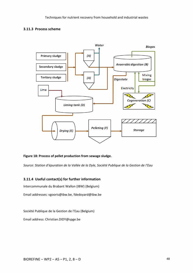
Techniques for nutrient recovery from household and industrial wastes
BIOREFINE – WP2 – A5 – P1, 2, 8 – D 48
3.11.3 Process scheme
Figure 18: Process of pellet production from sewage sludge.
Source: Station d’épuration de la Vallée de la Dyle, Société Publique de la Gestion de l’Eau
3.11.4 Useful contact(s) for further information
Intercommunale du Brabant Wallon (IBW) (Belgium)
Email addresses: [email protected], [email protected]
Société Publique de la Gestion de l’Eau (Belgium)
Email address: [email protected]

Techniques for nutrient recovery from household and industrial wastes
BIOREFINE – WP2 – A5 – P1, 2, 8 – D 49
3.12 Incineration and metal recovery from household and industrial wastes (designed by SELCHP, UK)
South East London Combined Heat and Power (SELCHP) is an advanced Energy Recovery Facility built
through a partnership between the public and private sectors. Opened in 1994 in South London,
SELCHP is now regarded as an example of industry best practice, with similar facilities modelled on
its design being constructed around the world.
3.12.1 General description
SELCHP receives waste from households and businesses. The waste is tipped into a bunker, where a
crane grabs it and places it into the feed hopper. It then drops down a feed chute onto a sloping
grate where it is constantly turned over so as to allow all combustion phases (such as drying, ignition
and combustion itself) to happen simultaneously and a constant high temperature to be maintained.
Ash from the burning process is transferred by an ash discharger and residue handling system to the
ash pit. During the transfer, ferrous metals are removed for recycling and the purified ash is recycled
as material for road building or construction use.
The hot gases produced in the combustion process pass through a water tube boiler where they are
cooled. The heated water is transformed into steam. A turbo-generator uses the steam to produce
electricity for the National Grid.
The gases from the boiler go through a complex flue gas cleaning process, involving the injection of a
dilute ammonia solution to reduce nitrogen oxides to nitrogen and water, lime milk to neutralise
acid gases and activated carbon to absorb heavy metals and potential remaining dioxins.
Finally, the dust particulates are removed from the gas stream by a bag filter before the cleaned gas
is released into the air. The resultant material known as Air Pollution Control Residue (APC Residue)
is sent to a licensed hazardous waste site for disposal.
The power is generated when the steam leaves the boilers at a 395 °C temperature and a 46 bar
pressure , and is fed directly into a single 35 MW steam turbine generator. The turbine rotates the
generator to produce electricity. The steam from the turbine is also used to pre-heat the combustion
air for the waste burning process.
The exhaust steam from the turbine is recycled as water (returning into the process) by air-cooled
condensers. Electricity is generated at 11kV and transformed up to 132 kV for export to the London
Electricity system which passes very close to the SELCHP facility. No supplementary fuel is required
to maintain combustion, just refuse and controlled addition of air.
Accepted Waste
SELCHP facility is designed to handle and treat normal domestic refuse and similar waste. This is
defined 'acceptable' and 'unacceptable' waste. 'Acceptable' waste is household and commercial
waste which is considered suitable for incineration.

Techniques for nutrient recovery from household and industrial wastes
BIOREFINE – WP2 – A5 – P1, 2, 8 – D 50
The type of waste that is accepted at SELCHP for incineration is: 'rubbish and refuse normally
collected and disposed of by residential households and commercial or institutional establishments'.
This does not include wastes in quantities and concentrations which need special handling when
processed and disposed of. Those include bulky items, waste oil and other items of 'unacceptable'
waste.
Acceptable wastes include leaves, twigs, grass and offcut from plants, paper, plastics, ferrous and
non-ferrous metals, glass and other materials present in household refuse. In order to avoid errors,
Hazardous Waste as defined by the Hazardous Waste Directive (Council Directive 91/689/ECJ) is
seen as unacceptable waste.
Unaccepted Waste
Processing any of the following materials may cause severe injury and damage:
- builders waste, liquid waste, non-burnable construction material, demolition debris
especially, plaster plates,
- gas cylinders, beer kegs or any other pressure cylinders,
- petrol, oils, greases, solvents or paints,
- animal or human remains or waste,
- acid or caustic substances,
- clinical, pathological and biological wastes,
- asbestos substances,
- tree trunks,
- large quantities of sulphur containing materials,
- machinery other than small household items,
- drugs or poisons,
- motor vehicle batteries, motorcycles, motor engines, transmissions, rear ends, springs,
fenders and major parts of motor vehicles, trailers, agricultural equipment, boats and ships,
farm and other large machinery,
- items weighing more than 25 kg each,
- items larger than 1.2 m,
- items larger than 1.2 m x 0.15 m x 0.15 m,

Techniques for nutrient recovery from household and industrial wastes
BIOREFINE – WP2 – A5 – P1, 2, 8 – D 51
- domestic 'white goods' such as fridges, freezers, washing machines, etc.
3.12.2 Unit operations
Air-Cooled Condenser (1)
The eight electrically powered fans push air through the finned tubes of the condenser so as to cool
the low pressure steam from the turbine exhaust. Cooling condenses the steam back to water which
is recycled back into the boilers, therefore minimising water usage in normal operating conditions.
Steam Turbine and Generator (2)
Steam arrives from the boilers, driving the turbine, which rotates the generator in order to produce
electricity. The electricity leaves via 11,000 volt cables lying across the floor.
Tipping Hall (3)
Vehicles drive up a slope into the tipping hall. They then reverse to the edge of the pit and empty
their contents into it.
Refuse Bunker (4)
Two semi-automatic cranes transfer refuse to boilers which burn up to 29 tons per hour. Each grab
lifts up to 5 tons of refuse. Normally there are 4,500 tons of refuse in the bunker. The bunker can
hold up to 6,000 tons.
Feed Hopper (5)
The refuse from the crane grabs is dropped here and fed onto the incineration grate in a controlled
manner.
Incineration Grate (6)
By pulling down the handle on the right-hand side of the viewing port and looking up at 45 oC to
observe the combustion of refuse, it is possible to see the ash falling into the cooling bath below.
Steam Boiler (7)
Refuse is dropped into the chutes. Hydraulic rams feed refuse onto the grate, where it burns at
temperatures over 850 °C. Heat energy is released into a multi pass boiler where 76 tons of steam
are produced each hour at 395 °C and 46 bar.

Techniques for nutrient recovery from household and industrial wastes
BIOREFINE – WP2 – A5 – P1, 2, 8 – D 52
Gas Treatment Scrubber (8)
As the hot combustion gases pass here, they are mixed and cooled with a measured amount of lime
milk sprayed in at the top. The lime falls through the gases, reacting with them, removing the acid
ones and reaching the bottom, where it is removedin powder form. The incoming acid gas content is
continuously measured to make sure the right amount of lime is added.
Bag House Filter (9)
The bag house contains around 3,000 individual bag filters. All the gases from the waste combustion
pass through the filter bags and all dusts are captured on the filter material. The cleaned gases are
then emitted from the chimney stack. The dust is periodically dislodged from the bags by a pulse of
compressed air. This removed dust becomes part of the Air Pollution Control residue.
Induced Draught Fan (10)
A powerful adjustable fan draws all the gases through the plant, keeping the whole process under a
slight vacuum and ensuring there are no leaks.
Residue Handling Crane (11)
This device transfers the bottom ash and recovered ferrous metal to loading chutes prior to
discharge into lorries for removal from site.
Bottom Ash Handling (12)
After combustion, the volume of the original refuse is reduced by 90 % and the mass by 70 %. From
this remaining bottom ash, an off-site joint venture business recycles a further 1.5 % of ferrous
metal and up to 1.5 % of non-ferrous metal such as aluminium, copper and brass. The off-site
business also processes the bottom ash to produce a high performance aggregate, sold for use in
road construction and other purposes.
Under Fire Fan (13)
These large ducts draw air from above the waste pit through the concrete wall to the west. The air is
fed into the furnace via fans from both below and above the flames. This air is vital to maintain the
correct combustion of the waste. Drawing the air from around the waste pit also stops smells from
spreading through the neighbourhood.

Techniques for nutrient recovery from household and industrial wastes
BIOREFINE – WP2 – A5 – P1, 2, 8 – D 53
Water Treatment Plant (14)
Two exchange units treat incoming mains water at the rate of 10 tons per hour per unit. The treated
water is then used in the boilers for the production of steam intended to drive the turbine.
The process scheme is shown in Figure 19.
3.12.3 Process scheme
Figure 19: Process scheme of the South East London Combined Heat and Power Plant.
Source: Website of South East London Combined Heat and Power Plant
3.12.4 Useful contact(s) for further information
South East London Combined Heat and Power Plant (United Kingdom)
Email address: see website http://www.selchp.com/
University of Leeds (United Kingdom)
Email addresses: [email protected], [email protected], [email protected]

Techniques for nutrient recovery from household and industrial wastes
BIOREFINE – WP2 – A5 – P1, 2, 8 – D 54
3.13 Incineration and metal recovery from household and industrial wastes (designed by LondonWaste)
3.13.1 General description
LondonWaste provides waste management services across London. The facilities recycle materials,
compost organic waste and recover energy from waste. Waste considered unsuitable for other
methods of recycling is sent to the Energy Centre. Here, waste is incinerated to produce energy. The
heat generated from the process turns water into steam which drives turbines to create electricity.
This is fed into the National Grid. The export is around 85 % of the electricity generated in
LondonWaste, which represents enough to power 72,000 homes throughout the year. The
remaining 15 per cent power all the EcoPark centres. From 1994, when LondonWaste Ltd was
awarded the NLWA contract, till the end of 2013, more than 9 million tons of waste have been
diverted from landfill.
3.13.2 Unit operations
Waste Input (1)
Residual Waste is delivered to the Energy Centre, generally by refuse collection vehicles and
deposited into the bunkers.
Bunkers (2)
There are five bunkers, each about 25 m deep and 14 m².
Overhead Grab Cranes (3)
There are three grabs which lift the waste from the bunkers and place it into one of the five feed
chutes. The boilers are fed at a rate of 15 tons per hour.
Boiler Feed Chute (4)
The waste is put onto the boiler grates at a pace controlled by a hydraulic ram.
Boiler grate (5)
Waste is burnt on the grate at temperatures over 1000 °C.

Techniques for nutrient recovery from household and industrial wastes
BIOREFINE – WP2 – A5 – P1, 2, 8 – D 55
Boiler (6)
Above the grate is the tube area where the hot gas is used to generate superheated steam from 40
tons of water every hour. The steam from the boiler is used to drive turbines and generate
electricity.
Ash (7)
Ash from the boiler grates is sent to an on-site ash recycling plant. The processors remove any
further metals for re-use and then grade and screen the ash for use as an aggregate in road building
and contruction.
Economiser (8)
To ensure that the maximum amount of energy is recovered from the waste, the hot gases from the
boiler flow into the economiser where they heat the incoming boiler water.
Precipitator (9)
The gases, now cooled to about 180 °C, carry on into the first part of the gas cleaning plant, the
precipitator. Wires and plates in the precipitator are charged with electrostatic electricity where
they attract the dust out of the flue gas.
Flue gas treatment plant (10)
The purpose of the flue gas treatment plant is to clean the flue gas before it enters the atmosphere.
The first part of the process cools the gas to 140 °C by adding water. Lime and activated carbons are
then injected into the gas stream to neutralize any acidity and absorb other pollutants.
Fabric Filter (11)
All the gas is filtered through an extremely fine fabric to remove remaining dust and lime before
flowing through the 100 metre high chimney.
Chimney (12)
All the gases are continuously monitored to ensure compliance with very strict regulations. A slight
plume, which is only water vapour, may be visible under some conditions.

Techniques for nutrient recovery from household and industrial wastes
BIOREFINE – WP2 – A5 – P1, 2, 8 – D 56
Alternator (13)
After supplying the internal needs, more than 85 % of the electricity generated by the plant are
exported to the National Grid. The export reaches 35,000 KW of power per hour.
The process scheme of the treatment is shown in Figure 20.
3.13.3 Process scheme
Figure 20: Process scheme of the LondonWaste Plant.
Source: Website of LondonWaste
3.13.4 Useful contact(s) for further information
LondonWaste Plant (United Kingdom)
Email address: [email protected]
University of Leeds (United Kingdom)
Email addresses: [email protected], [email protected], [email protected]

Techniques for nutrient recovery from household and industrial wastes
BIOREFINE – WP2 – A5 – P1, 2, 8 – D 57
3.14 Removal of heavy metals from sludge and sedim ents
3.14.1 General description
The CTP (Centre Terre et Pierre) is located in Tournai (Wallonia, Belgium). Its activities consist in
treating ores, industrial minerals, recycling solid materials, and contaminated soils, sediments and
dredging spoils. The analysis lab of the CTP is able to achieve complete physical, chemical and
mineralogical analyses of mineral materials. The center is also an authorized laboratory for waste
analysis by the Walloon Region. The 3,400 m² center is equipped with different types of
comminution and sorting devices able to treat up to several tons of materials.
The aim of the SOLINDUS platform is to validate recycling techniques applied to solid materials on a
partly industrialized scale. The treatment presented in this section explains a method which leads to
different fractions with defined and homogeneous particle size distribution, and complementary unit
operations can be added to the original technique. This process can be used to remove heavy metals
from silt-like materials obtained after wet treatment of different types of sludge or soil, and
therefore be used to purify the materials and increase their quality as fertilizers. Industrial sludge
and sediments can be treated, but ashes should also be considered.
The treatment is mainly composed of 8 important stages:
- Removal of big particles (> 2mm),
- Removal of particles the size of which is superior to 250 µm,
- Removal of particles the size of which is superior to 63 µm,
- Removal of particles the size of which is superior to 15 µm,
- Purification of the muddy fraction,
- Flocculation/decantation of the clayey fraction,
- Dehydration of the different fractions,
- Water treatment (not described here).
The raw material is taken to a first trommel by hydraulic excavators through a grid that retains
blocks bigger than 20 mm. This trommel divides the material into two fractions depending on their
sizes. Two fractions are obtained: one made of wastes the size of which is superior to 4 mm, and one
composed of wastes the size of which is inferior to 4 mm. After that, a vibrating sieve makes it
possible to obtain a finer fraction (size inferior to 2 mm). The two fractions composed of the biggest
elements are put together to make up the first waste fraction (Fraction 1, size superior to 2 mm).
The finest fraction is then homogenized and mixed with water before being sent to a curved sieve.
This results in a second fraction (Fraction 2) mainly composed of sand particles (between 250 µm
and 2 mm). A further unit operation consisting in magnetic separation can be achieved in Fraction 2
if it contains ferromagnetic materials. The materials are then sent to a vessel in which the pulp
density is modified and adjusted to the right value.
Techniques for nutrient recovery from household and industrial wastes
BIOREFINE – WP2 – A5 – P1, 2, 8 – D 58
The pulp, which is composed of particles the size of which is inferior to 250 µm, is then sent to a
hydro-cyclone combined with a screw classifier. This combined system leads to a fine fraction
(particle size inferior to 63 µm) and Fraction 3, composed of fine sands. This third fraction then goes
through further stages: attrition (optional) and spiral gravity separation, after which the material is
dehydrated by big bag filters.
The finest fraction is then composed of particles the size of which is inferior to 63 µm. The pulp is
sent to two parallel hydro-cyclones, which generates a muddy fraction (particle size from 15 to 63
µm) and a clayey fraction (size inferior to 15 µm). The muddy fraction is next purified in a flotation
tank so as to separate metallic and organic pollutants with a technique based on their hydrophobic
nature. Different substances are added to the pulp during this process in order to collect the
pollutants in the foam (supposed to contain metals and organic pollutants). The purified muddy
fraction is then decanted and filtered, giving Fraction 4.
The clayey fraction is sent to a flocculation/decantation system. The pulp is mixed with flocculation
reagents in a tank to improve and accelerate the sedimentation process. The pulp, which has been
thickened, is next sent to a filter press to be dehydrated. This final stage provides the finest fraction
of all, called Fraction 5.
3.14.2 Unit operations
Screening by a trommel (A)
The first unit operation is a screening phase achieved with a trommel composed of a rotary drilled
cylinder. The blades inside the cylinder mix the material. An aspersion device is also included in the
system to facilitate the de-agglomeration of the material. The device can treat a maximal input flow
of 1 to 1.5 m³/h, with a percentage of DM comprised between 50 and 60 %. Three fractions are
obtained (particle size superior to 20 mm, manually removed from a grid at the feeding end of the
trommel, inferior and superior to 4 mm, which is the size of the holes in the inner cylinder of the
trommel).
Screening by a vibrating sieve (B)
The second unit operation is another screening stage achieved on a vibrating sieve. Water is brought
to the material in order to facilitate the mass transfers. The device can treat a maximal input flow of
1.5 to 2 m³/h, with a percentage of DM between 30 and 40 %. The output flow contains about 20 %
of DM. Two fractions are obtained (particle size inferior and superior to 2 mm).
Mixing stage (1) (C)
A mixing stage is necessary to homogenize the material, added with water to obtain pulp. The
maximal input flow can reach 2 m³/h.

Techniques for nutrient recovery from household and industrial wastes
BIOREFINE – WP2 – A5 – P1, 2, 8 – D 59
Screening on a curved sieve (D)
This separation device is composed of small metallic blades separated by gaps of 500 µm. The
maximal input flow can reach 5 m³/h, with a percentage of DM varying from 10 to 20 %. Two
fractions are obtained (particle size inferior and superior to 250 µm).
Magnetic separation (E)
A magnetic separator can be integrated into the process if necessary. It consists of a rotary device
equipped with a permanent magnet. The magnetic particles are retained by the magnet before
being released in a zone in which the magnetic field is weaker. The device can treat an input flow of
5 m³/h with a percentage of DM from 10 to 20 %.
Mixing stage (2) (F)
A second mixing stage is needed to reach a specific density. The percentage of DM must be between
5 and 10 % in the output flow. Water is added in the tank to dilute the pulp. The device can treat an
input flow of 5 m³/h with a percentage of DM varying from 10 and 20 %.
Screening by a combined system (hydro-cyclone/screw classifier) (G)
A combined device composed of a hydro-cyclone and a screw classifier is used to treat the fraction
the particle size of which is inferior to 250 µm. This system generates two fractions: the fine sands
composed of particles with sizes between 63 and 250 µm and the fine fraction composed of the
smallest particles (size inferior to 63 µm). The device can treat an input flow of up to 12 m³/h with a
percentage of DM from 5 to 10 %.
Attrition (optional) (H)
This unit operation can be added to the process if necessary and is applicable to fine sands (size
between 63 and 250 µm, G). This system is located at the end of the screw classifier and is
composed of blades creating strong currents. Those currents allow to clean the particle surfaces and
remove hydrocarbons, metal oxides, etc. The machine can treat a maximal input flow of 1 m³/h with
a percentage of DM varying from 50 to 70%.
Screening by a hydro-cyclone and spiral devices (I)
This step is applicable to the fine sands obtained in (G). A hydro-cyclone is used to ensure a particle
size varying from 63 to 250 µm. Two in-line spiral separators generate a fine water blade to separate
the particles according to their weights. The heaviest particles (minerals) staying close to the axis of
the spiral are collected by the inner valve at the bottom of the spiral while the lightest particles
(organic matter) are collected by the outer valve. Small valves collect the different fractions. The

Techniques for nutrient recovery from household and industrial wastes
BIOREFINE – WP2 – A5 – P1, 2, 8 – D 60
finest and lightest particles tend to go to the spiral extremity because of the turbulences combined
with the centrifugal force. The system can treat an input flow of 5 m³/h with a percentage of DM
varying from 5 to 10%.
Filtration (J)
The finest fractions obtained thanks to the action of the spiral separators are dehydrated by big bag
filters.
Concentration of the heavy fraction by a hydro-cyclone and filtration (K)
The heavy fraction collected by the spiral separators is next treated on a vibrating screen for
dehydration. This combined device can treat a maximal input flow of 1 m³/h with a percentage of
DM varying from 10 to 20 %.
Mixing stage (3) (L)
The finest fraction obtained in (G) by the action of the hydro-cyclone combined with the screw
classifier (particle size inferior to 63 µm) is sent to a mixing vessel. This vessel is used to homogenize
the material and dilute it with water. The maximal input flow which can be treated is 10 m³/h with a
percentage of DM varying from 5 to 10 %.
Screening by parallel hydro-cyclones (M)
The finest fraction which has been homogenized is next sent to two parallel hydro-cyclones. This
device leads to two fractions: a muddy fraction composed of bigger particles (size between 15 and
63 µm) and a clayey fraction composed of small particles (size inferior to 15 µm). The system can
treat a maximal input flow of 15 m³/h with a percentage of DM from 5 to 10 %.
Purification of the muddy fraction by a hydro-cyclone (N)
The muddy fraction resulting from the previous stage (M) is next sent to another hydro-cyclone
before being treated in the flotation device.
Purification by flotation (O)
The aim of the flotation device is to remove the metallic and organic pollutants present on the
muddy particles. Reagents are prepared separately before being fed into the flotation tank. Air is
injected into the tanks and different types of reagents can be added: activating reagents, foaming
reagents, etc. Two in-line tanks of 750 L allow the foam containing the concentrated pollutants to be
collected at the surface. The maximal input flow can reach 1.5 m³/h, with a percentage of DM

Techniques for nutrient recovery from household and industrial wastes
BIOREFINE – WP2 – A5 – P1, 2, 8 – D 61
varying from 20 to 30 %. The reagents are chosen according to their ‘ability’ to select the pollutants
or nutrients to be removed and need a targeted preliminary study carried out in a laboratory.
Decantation stage (P)
The foam resulting from the flotation process and the clean muddy fraction are next sent to a
decantation device consisting of two tanks of 4.9 m³. The first decantation tank treats the polluted
foam (containing the metallic elements, or micronutrients), while the second one treats the clean
fraction.
Filtration (Q)
Both fractions obtained in (P) after the decantation step are next sent to big bag filters.
Flocculation and decantation of the clayey fraction (R)
The natural decantation of the clayey fraction is very slow and requires flocculation reagents to be
accelerated. Those reagents are prepared in a separate mixing tank by dissolving the powder. The
flocculation agents are then added to the clayey fraction in pulp form. The material mixed with the
flocculation reagents is sent to a decantation tank of 35 m³. A maximal input flow of 10 m³/h with a
percentage of DM of about 5 % can be treated in this device.
Dehydration of the clayey fraction (S)
The flocculated particles are dehydrated by a filter press. The device consists of 30 units and the
internal pressure can reach a maximal value of 15 bar, allowing to reach a final DM of 70% without
any other additives. One dehydration cycle takes between 1 and 2 hours per ton of final material
obtained. This final phase allows to recover the finest fraction of the raw material in the shape of
compressed cakes which are easy to handle.
The scheme of the process is shown in Figure 21.

Techniques for nutrient recovery from household and industrial wastes
BIOREFINE – WP2 – A5 – P1, 2, 8 – D 62
3.14.3 Process scheme
Figure 21: Scheme of the process used by the “Centre Terre et Pierre” to purify sludge and
sediments.
Source: Centre Terre et Pierre (Tournai, Belgium)

Techniques for nutrient recovery from household and industrial wastes
BIOREFINE – WP2 – A5 – P1, 2, 8 – D 63
3.14.4 Additional comments
Some unit operations can be added to the process if necessary. The magnetic separation (E) and the
attrition stage (H) are optional. A water treatment process - which is not described here - is also part
of the system. The pilot plant is being extended in order to integrate other unit operations such as jig
separation (heavy/light fraction separation combined with granulometry-oriented separation in wet
conditions) and will be fully operational in February 2016.
All this data was kindly provided by the “Centre Terre et Pierre” in Tournai (Belgium).
3.14.5 Useful contact(s) for further information
Centre Terre et Pierre (Belgium)
Email addresses: [email protected] ; [email protected]
3.15 Removal of metallic compounds from ashes (IPAL LE, Belgium)
3.15.1 General description
The waste incinerator of Thumaide is managed by the inter-municipal organization IPALLE (Wallonia,
Belgium). Its activities consist in recovering different types of materials through incineration. The
plant processes bulky wastes, industrial and household wastes, medical and hospital wastes, plastics,
cardboard, sewage sludge, etc. The post-incineration residue is clinker and its composition is quite
variable because of the heterogeneity of the input flows. The plant treats about 300,000 tons of
material every year.
The aim of the clinker-generating plant is to separate the different fractions according to their sizes
as well as their magnetic and metallic characteristics. It is possible to identify the techniques best
suited to the various fractions.
The treatment consists of 4 main kinds of processes:
- Screening stages,
- Magnetic separations,
- Metallic separation based on an eddy current separator,
- Mixing step.
The raw material is brought to a first screening sieve to separate the input flow into two fractions:
one made up of wastes the size of which is superior to 100 mm and one composed of wastes the size
of which is inferior to 100 mm.
The biggest fraction is next sent to a magnetic separator, producing a fraction of big magnetic
particles (size > 100 mm) and a fraction of big non-magnetic particles (size > 100 mm).

Techniques for nutrient recovery from household and industrial wastes
BIOREFINE – WP2 – A5 – P1, 2, 8 – D 64
The finest fraction is composed of the finest particles (size inferior to 100 mm). This flow is sent to a
screening trommel which provides two fractions: the smaller one composed of particles the size of
which is inferior to 20 mm and the bigger one made up of particles the size of which is varies from 20
to 100 mm.
The fraction is sent to another magnetic separator which generates a magnetic and a non-magnetic
fraction of fine particles. The fine magnetic fraction is sent to a mixing tank while the non-magnetic
flow is sent to an eddy current separator. This plant allows to separate the metallic compounds
contained in the material. The eddy current separator generates a non-metallic flow of fine particles
and a second fraction of non-magnetic metals (size inferior to 20 mm).
The flow composed of medium-sized particles (size from 20 to 100 mm) resulting from the size-
bound separation achieved in the trommel is next sent to a magnetic separator. This device
generates two fractions, a magnetic one and a non-magnetic one. The magnetic fraction is mixed
with the finest particles in the mixing tank. This mix is then sent to another magnetic separator
which creates two different flows: the fine magnetic particles (size inferior to 100 mm) and the fine
non-magnetic particles (size between 20 and 100 mm).
Finally, the non-magnetic fraction resulting from the magnetic separation following trommel
screening is mixed with the above-mentioned non-magnetic fine particles. Those two combined
flows are composed of medium-sized non-magnetic particles (size between 20 and 100 mm).
3.15.2 Unit operations
Primary screening sieve (A)
The raw material is first sent through a primary sieve, which leads to two different flows. Those two
fractions consist of a fine fraction (size < 100 mm) and of a big one (size > 100 mm). The input flow is
composed of about 67 % of household wastes, 23 % of industrial wastes, 7 % of sewage sludge and 2
% of hospital wastes.
Magnetic separation (1) (B)
A magnetic separator processes the biggest particles coming from the screening sieve, which results
in a magnetic fraction of big particles and in a non-magnetic fraction of big particles (size superior to
100 mm).
Trommel screening (C)
A screening trommel is used to separate the particles composing the finest flow coming from the
primary sieve (size inferior to 100 mm). This screening device produces a fine fraction (size < 20 mm)
and a big(ger) one (size comprised between 20 and 100 mm).

Techniques for nutrient recovery from household and industrial wastes
BIOREFINE – WP2 – A5 – P1, 2, 8 – D 65
Magnetic separation (2) (D)
A further magnetic separator is used for the finest fraction (size < 20 mm). The input flow is divided
into a magnetic flow (next sent to a mixing tank (G)) and a non-magnetic flow which is sent to an
eddy current separator.
Eddy current separator (E)
The principle of the eddy current separator is based on the magnetic properties of the elements but
it is more complex than the one of a common magnetic separator. The swirl is due to a high-
frequency magnetic flux. A rotating device equipped with permanent magnets makes it possible to
create specific magnetic fields. The magnets have alternating magnetic poles. The rotation of the
device causes a variation in the magnetic field, which causes a repulsion of the metallic elements.
The device creates both a flow of fine non-metallic particles and one of fine metallic elements
(particle size inferior to 20 mm).
Magnetic separation (3) (F)
The intermediate fraction (size between 20 and 100 mm) obtained in (C) is then sent to another
magnetic separator. The device generates a flow of fine magnetic particles and one of fine non-
magnetic particles (size between 20 and 100 mm).
Mixing step (G)
The aim of the mixing tank is to homogenize the magnetic fractions obtained in (D) and (F). Both
fractions are mixed together in the tank before being sent to (H).
Magnetic separation (4) (H)
This final magnetic separator creates two flows: the magnetic fraction of fine particles (size inferior
to 100 mm) and the non-magnetic fraction of fine particles. This flow is mixed with the one coming
from (F). A blower is then used to remove the finest particles, generating a non-magnetic fraction of
particles the size of which varies from 20 to 100 mm.
The process scheme is shown in Figure 22.

Techniques for nutrient recovery from household and industrial wastes
BIOREFINE – WP2 – A5 – P1, 2, 8 – D 66
3.15.3 Process scheme
Figure 22: Scheme of the process used by IPALLE to purify ashes.
Source: IPALLE (Belgium)
3.15.4 Additional comments
This plant is used to sort the different clinker fractions. It separates the magnetic elements from the
non-magnetic ones but disregards macronutrients (phosphorus, nitrogen and potassium).
All this data was kindly provided by the inter-municipal organization IPALLE (Belgium).

Techniques for nutrient recovery from household and industrial wastes
BIOREFINE – WP2 – A5 – P1, 2, 8 – D 67
3.15.5 Useful contact(s) for further information
IPALLE (Belgium)
Email address: [email protected]

Techniques for nutrient recovery from household and industrial wastes
BIOREFINE – WP2 – A5 – P1, 2, 8 – D 68
4 List of useful contacts
BELGIUM
Ecowerf
Aarschotsesteenweg 210, 3010 Kessel-Lo
Contact: see the website www.ecowerf.be
DLV InnoVision ESV
Rijkelstraat 28, 3550 Heusden-Zolder
Contact: Lies Bamelis, [email protected]
Gembloux Agro-Bio Tech – University of Liège
Passage des Déportés 2, 5030 Gembloux
Contacts: Frank Delvigne, [email protected] ; Cédric Tarayre, [email protected]
Intercommunale du Brabant Wallon (IBW)
Rue de la Religion 10, 1400 Nivelles
Contacts: Vincent Gooris, [email protected] ; François Dedoyard, [email protected]
IPALLE
Centre de valorisation des déchets de Thumaide
Rue de Ribonfosse 9, 7971 Thumaide
Contact: Laurent Dupont, [email protected]

Techniques for nutrient recovery from household and industrial wastes
BIOREFINE – WP2 – A5 – P1, 2, 8 – D 69
NuReSys
Rooseveltlaan 108/1, 8790 Waregem
Contact: Carl Dewaele, [email protected]
Société publique de la Gestion de l’Eau (SPGE)
Avenue de Stassart(NR) 15, 5000 Namur
Contact: Christian Didy, [email protected]
University of Ghent, Faculty of Bioscience Engineering
Coupure Links 653, 9000 Gent
Contacts: Erik Meers, [email protected] ; Evi Michels, [email protected]
Vlaamse Compostorganisatie (VLACO)
Stationsstraat 110, 2800 Mechelen
Contacts: Elke Vandaele, [email protected] ; Wim Vanden Auweele,
FRANCE
Sydeme-Méthavalor
Rue Jacques Callot 1, 57600 Morsbach
Contact: see the website www.sydeme.fr/site/equip_methanisation1.php
THE NETHERLANDS
Nijhuis Water Technology
Innovatieweg 4, 7007 CD Doetinchem
Contact: Frank Delgorge, [email protected]

Techniques for nutrient recovery from household and industrial wastes
BIOREFINE – WP2 – A5 – P1, 2, 8 – D 70
UNITED KINGDOM
LondonWaste EcoPark
Advent Way, N18 3 AG London
Contact: [email protected]
Severn Trent Water Ltd
PO Box 5310, CV3 9FJ Coventry
Contact: see the website www.stwater.co.uk
South East London Combined Heat and Power
SELCHP Energy Recovery Facility, Landmann Way Off Surrey Canal Road, SE14 5RS London
Contact: see the website www.selchp.com
Thames Water
Clearwater Court, Vastern Road, Reading, RG1 8DB West Berkshire
Contact: see the website www.thameswater.co.uk
University of Leeds
Faculty of Engineering, LS2 9JT Leeds
Contacts: Miller A. Camargo-Valero, [email protected] ; Andrew B. Ross,
EUROPE
European Sustainable Phosphorus Platform (ESPP)
Contact: [email protected]

Techniques for nutrient recovery from household and industrial wastes
BIOREFINE – WP2 – A5 – P1, 2, 8 – D 71
5 Bibliography
Abu-Orf, M., Stinson, B., Davies, G., Goss, T., Marija, P., Amad, S., Taylor, R., Belschner, D., Hartz, F. &
Hentz, L. (2011). Energy Recovery from Residuals ; Comparing Anaerobic Digestion with Combined
Heat and Power to Drying Gasification. Proceedings of the Water Environment Federation 2011 :
550-572.
Adam, C., Eicher, N., Hermann, L., Herzel, H., Mallon, J., Schaaf, M., Stemann, J. (2015). Comparative
review of ash processes.
Akinola, O. (2013). Overview of Phosphorus Recovery and Recycling From Selected Waste Streams -
Protecting Phosphorus as a Resource. MSc, Imperial College London.
Britton, A., Koch, F. A., Mavinic, D. S., Adnan, A., Oldham, W. K. & Udala, B. (2005). Pilot-scale
struvite recovery from anaerobic digester supernatant at an enhanced biological phosphorus
removal wastewater treatment plant. Journal of environmental engineering and science 4 : 265-277.
Clearfleau Ltd, (2013). Nestlé: Anaerobic Treatment and Energy Generation.
Clearfleau Ltd, (2015). Sweet success for Nestle's on-site anaerobic digestion plant.
Cooper, J. & Carliell-Marquet, C. (2013). A substance flow analysis of phosphorus in the UK food
production and consumption system. Resources, Conservation and Recycling 74 : 82-100.
Cordell, D., Drangert, J.-O. & White, S. (2009). The story of phosphorus: global food security and food
for thought. Global environmental change 19 : 292-305.
Cornel, P., Schaum, C. (2009). Phosphorus recovery from wastewater: needs, technologies and costs.
Water Sci. Technol. 59 : 1069–1076.
DEFRA, (2011). Anaerobic digestion strategy and action plan. In: Department for Environment, Food
and Rural Affairs (ed.). London, UK: Department for Environment, Food & Rural Affairs.
Desmidt, E., Ghyselbrecht, K., Zhang, Y., Pinoy, L., Van der Bruggen, B., Verstraete, W., Meesschaert,
B. (2015). Global phosphorus scarcity and full-scale P-recovery techniques-a review. Crit. Rev.
Environ. Sci. Technol. 45 : 336–384.
Di Iaconi, C., Pagano, M., Ramadori, R., Lopez, A. (2010). Nitrogen recovery from a stabilized
municipal landfill leachate. BioResource Technology 101 (2010): 1732-1736.
DIRKSE, E. (2015). Biogas upgrading using the DMT Carborex® PWS Technology.
Driessen, W. (2009). Sustainable Treatment of Reject Water and Industrial Effluent by Producing
Valuable Products. 14th European Biosolids and Organic Resources, 9-11 September 2009, Leeds,
UK. AquaEnviro.
Driessen, W. & Reitsma, G. (2014). One-Step ANAMMOX Process [Online]. UK Water Projects Online.
Available at http://www.waterprojectsonline.com/case_studies/Technologies/anammox_I&T.pdf.

Techniques for nutrient recovery from household and industrial wastes
BIOREFINE – WP2 – A5 – P1, 2, 8 – D 72
Driessen, W. (2014). PHOSPAQ®™ Process - Recovery of phosphorus by formation of struvite
[Online]. UK Water Projects Online. Available at
http://www.waterprojectsonline.com/case_studies/Technologies/PHOSPAQ®_I&T.pdf.
Durose, N. & Jeffcoat, T. (2014). Stoke Bardolph STW Centrate Scheme- first UK installation to utilise
the Phospaq, UASB+ and Anammox technologies in a single process solution [Online]. UK Water
Projects Online.
EcoWerf, year not specified. EcoWerf Afvalverwerking. Online
http://www.ecowerf.be/nl/getpage.asp?i=9#5.
Environment Agency, (2012). Review of best practice in treatment and reuse/recycling of
phosphorus at Wastewater Treatment Works. In: Environmental Agency (ed.). Bristol, UK.
Ewert, W., Hermanussen, O., Kabbe, C., Mêlè, C., Niewersch, C., Paillard, H., Stössel, E., Wagenbach,
A., Stemann, J. (2014). Description of sludge related processes.
Gueterbock, R. (2014a). The benefits of on-site AD (with Nestle Fawdon AD plant case study). In:
ASSOCIATION, A. D. A. B., ed. UK AD & Biogas 2014 Conference, Birmingham, England. Anaerobic
Digestion and Bioresources Association.
Gueterbock, R. (2014b). Smaller Scale, On-site Anaerobic Digestion – For Food & Beverage Sectors.
In: ALL-ENERGY, ed. All-Energy Conference, Glasgow, Scotland. All-Energy.
Hadden, D. (2009). Severn Trent First in Europe to Recycle Nutrients into “Environmentally Friendly”
Commercial Fertilizer [Online]. VANCOUVER, CANADA: OSTARA® Nutrient Recovery Technologies
Inc. Available at http://www.OSTARA®.com/news/news-releases/2009/severn-trent-first-europe-
recycle-nutrients-%E2%80%9Cenvironmentally-friendly%E2%80%9D-comme.
Kepp, U., Machenbach, I., Weisz, N. & Solheim, O. (2000). Enhanced stabilisation of sewage sludge
through thermalhydrolysis-three years of experience with full scale plant. Water Science &
Technology, 42 : 89-96.
Kim, D., Ryu, H., Kim, M., Kim, J., Lee, S. (2007). Enhancing struvite precipitation potential for
ammonia nitrogen removal in municipal landfill leachate. J. Hazard. Mater. 146 : 81–85.
Langerak, J., Lems, R., Giménez Dominguez P., Dirkse, E.H.M. (2013). Biogas upgrading: Membrane
separation take over. The success story of Poundbury continues. Available at http://www.dirkse-
milieutechniek.com/dmt/do/download/_/true/212310/Poundbury_Article_for_Manchester_V2JL_3
0_10_2013_1.pdf.
Lems, R., Dirkse, E.H.M. (2010). Small scale biogas upgrading: Green gas with the DMT Carborex® MS
system. 15th European Biosolids and Organic Resources Conference, Leeds, UK. AquaEnviro.
Lermen, A. (2013). Best practice example of an existing bio-methane gas grid injection plan. In:
GRIDS, G. G. (ed.).

Techniques for nutrient recovery from household and industrial wastes
BIOREFINE – WP2 – A5 – P1, 2, 8 – D 73
Li, X.Z., Zhao, Q.L. (2001). Efficiency of biological treatment affected by high strength of ammonium-
nitrogen in leachate and chemical precipitation of ammonium-nitrogen as pretreatment.
Chemosphere 44 : 37–43.
LondonWaste, year not specified. LondonWaste. Online http://www.londonwaste.co.uk/.
Moerman, W., Carballa, M., Vandekerckhove, A., Derycke, D., Verstraete, W. (2009). Phosphate
removal in agro-industry: Pilot- and full-scale operational considerations of struvite crystallization.
Water Res. 43 : 1887–1892.
Morgenschweis, C. (2011). The Pearl® technology [Online]. Available at
http://grontmij.com/highlights/water-and-energy/Documents/The-Pearl-Technology.pdf.
NuReSys, (2015). The Technology [WWW Document]. Available at
http://nuresys.be.apache22.hostbasket.com/?page_id=11.
Ofwat, (2005). Water Framework Directive – Economic Analysis of Water Industry Costs In: Ofwat
(Water Services Regulation Authority) (ed.). England: Ofwat - The Water Services Regulation
Authority.
Oloibiri, V.A. (2013). Ozonation of biologically treated landfill leachate. Ghent University.
OSTARA®, (2013). UK’s First Commercial Nutrient Recovery Facility. Thames Water’s Slough Sewage
Treatment Works [Online]. Slough, UK: OSTARA®. Available at
http://www.OSTARA®.com/sites/default/files/pdfs/OSTARA®-THAMES_case_study.pdf.
OSTARA®, (2014). Pearl® 2000 Nutrient Recovery Process [Online]. Available at
http://www.ostara.com/sites/default/files/pdfs/E-Pearl2000_brochure.pdf.
Panter, K. (2001). Getting the Bugs Out of Digestion and Dewatering with Thermal Hydrolysis.
Proceedings of the Water Environment Federation 2001 : 54-64.
P-REX, (2015). Pearl Struvite crystallisation in sludge liquor [Online]. P-REX Project - Practical
implementation of phosphorus recovery and recycling from wastewater stream in Europe. Available
at http://p-rex.eu/uploads/media/PREX_Factsheet_PEARL.pdf.
Remy, M. (2014). Integrated Solution for Nutrient Removal. LIFT Phosphorus Recovery Focus Group
Meeting. Portland, Oregon.
Ross, D., Shrive, C., Chauvin, D., Harnum, J. & Constantine, T. (2010). The Power of Sludge
Maximizing Energy Recovery at the Woodward Avenue WWTP in Hamilton, Ontario. Proceedings of
the Water Environment Federation 2010 : 1141-1149.
Sartorius, C., Horn, J. Von, Tettenborn, F. (2012). Phosphorus Recovery from Wastewater—Expert
Survey on Present Use and Future Potential. Water Environ. Res. 84 : 313–322.
Schoumans, O.F., Bouraoui, F., Kabbe, C., Oenema, O., van Dijk, K.C. (2015). Phosphorus
management in Europe in a changing world. Ambio 44 : 180–192.

Techniques for nutrient recovery from household and industrial wastes
BIOREFINE – WP2 – A5 – P1, 2, 8 – D 74
SELCHP, year not specified. Virtual Tour. Online http://www.selchp.co.uk/about-selchp/virtual-tour/.
Tillier, R. (2013). Oxford STW Bio Thelys® thermal hydrolysis plant provides green energy from
sewage sludge [Online]. UK Water Projects 2013. Available at
http://www.waterprojectsonline.com/case_studies/2013/Thames_Oxford_2013.pdf.
Vlaco vzw, (2015). Vlaco vzw: Professionele verwerking. Online www.vlaco.be.
Vale, P. (2013). Phosphorus Recovery from Wastewater. END-O-SLUDG Conference. Sludge and
Phosphorus Management in Europe: Present and Future., London.
Wentworth, J. (2014). Phosphate Resources. In: Parliamentary Office of Science and Technology
(ed.). The Parliamentary Office of Science and Technology.
Wild, R. (2014). Full Scale Phosphorus Recovery in Severn Trent Water. A UK Nutrient Platform?
Leeds, UK.