Bioinspiration from fish for smart material design and …glauder/reprints_unzipped/Aug... ·...
13
IOP PUBLISHING SMART MATERIALS AND STRUCTURES Smart Mater. Struct. 20 (2011) 094014 (13pp) doi:10.1088/0964-1726/20/9/094014 Bioinspiration from fish for smart material design and function G V Lauder 1 , P G A Madden 1 , J L Tangorra 2 , E Anderson 3 and T V Baker 3 1 The Museum of Comparative Zoology, Harvard University, 26 Oxford Street, Cambridge, MA 02138, USA 2 Department of Mechanical Engineering, Drexel University, Philadelphia, PA 19104, USA 3 Department of Mechanical Engineering, Grove City College, Grove City, PA, USA E-mail: [email protected] Received 31 January 2011, in final form 13 April 2011 Published 30 August 2011 Online at stacks.iop.org/SMS/20/094014 Abstract Fish are a potentially rich source of inspiration for the design of smart materials. Fish exemplify the use of flexible materials to generate forces during locomotion, and a hallmark of fish functional design is the use of body and fin deformation to power propulsion and maneuvering. As a result of nearly 500 million years of evolutionary experimentation, fish design has a number of interesting features of note to materials engineers. In this paper we first provide a brief general overview of some key features of the mechanical design of fish, and then focus on two key properties of fish: the bilaminar mechanical design of bony fish fin rays that allows active muscular control of curvature, and the role of body flexibility in propulsion. After describing the anatomy of bony fish fin rays, we provide new data on their mechanical properties. Three-point bending tests and measurement of force inputs to and outputs from the fin rays show that these fin rays are effective displacement transducers. Fin rays in different regions of the fin differ considerably in their material properties, and in the curvature produced by displacement of one of the two fin ray halves. The mean modulus for the proximal (basal) region of the fin rays was 1.34 GPa, but this varied from 0.24 to 3.7 GPa for different fin rays. The distal fin region was less stiff, and moduli for the different fin rays measured varied from 0.11 to 0.67 GPa. These data are similar to those for human tendons (modulus around 0.5 GPa). Analysis of propulsion using flexible foils controlled using a robotic flapping device allows investigation of the effect of altering flexural stiffness on swimming speed. Flexible foils with the leading edge moved in a heave show a distinct peak in propulsive performance, while the addition of pitch input produces a broad plateau where the swimming speed is relatively unaffected by the flexural stiffness. Our understanding of the material design of fish and the control of tissue stiffness is still in its infancy, and the development of smart materials to assist in investigating the active control of stiffness and in the construction of robotic fish-like devices is a key challenge for the near future. (Some figures in this article are in colour only in the electronic version) 1. Introduction Fish, as a result of their 500 million year evolutionary history, have evolved a remarkable variety of materials and configurations of these materials that allow them to swim, feed, reproduce, and locomote in the aquatic realm. Fish represent an elegant solution to the problem of moving through water at larger length scales. And although other types of evolutionary design solutions to this problem have occurred during the history of life, fishes are well known for the diversity of their locomotor abilities, with some species able to achieve high- speed locomotion and migrate many thousands of miles, while other species excel at low-speed maneuverability. Fishes are also striking for the diversity of body shapes and fin positions and sizes (Helfman et al 1997, Lauder 2006, Marshall 1971), with noteworthy examples including the variety of tail shapes 0964-1726/11/094014+13$33.00 © 2011 IOP Publishing Ltd Printed in the UK & the USA 1
Transcript of Bioinspiration from fish for smart material design and …glauder/reprints_unzipped/Aug... ·...

IOP PUBLISHING SMART MATERIALS AND STRUCTURES
Smart Mater. Struct. 20 (2011) 094014 (13pp) doi:10.1088/0964-1726/20/9/094014
Bioinspiration from fish for smart materialdesign and functionG V Lauder1, P G A Madden1, J L Tangorra2, E Anderson3 andT V Baker3
1 The Museum of Comparative Zoology, Harvard University, 26 Oxford Street, Cambridge,MA 02138, USA2 Department of Mechanical Engineering, Drexel University, Philadelphia, PA 19104, USA3 Department of Mechanical Engineering, Grove City College, Grove City, PA, USA
E-mail: [email protected]
Received 31 January 2011, in final form 13 April 2011Published 30 August 2011Online at stacks.iop.org/SMS/20/094014
AbstractFish are a potentially rich source of inspiration for the design of smart materials. Fish exemplifythe use of flexible materials to generate forces during locomotion, and a hallmark of fishfunctional design is the use of body and fin deformation to power propulsion and maneuvering.As a result of nearly 500 million years of evolutionary experimentation, fish design has anumber of interesting features of note to materials engineers. In this paper we first provide abrief general overview of some key features of the mechanical design of fish, and then focus ontwo key properties of fish: the bilaminar mechanical design of bony fish fin rays that allowsactive muscular control of curvature, and the role of body flexibility in propulsion. Afterdescribing the anatomy of bony fish fin rays, we provide new data on their mechanicalproperties. Three-point bending tests and measurement of force inputs to and outputs from thefin rays show that these fin rays are effective displacement transducers. Fin rays in differentregions of the fin differ considerably in their material properties, and in the curvature producedby displacement of one of the two fin ray halves. The mean modulus for the proximal (basal)region of the fin rays was 1.34 GPa, but this varied from 0.24 to 3.7 GPa for different fin rays.The distal fin region was less stiff, and moduli for the different fin rays measured varied from0.11 to 0.67 GPa. These data are similar to those for human tendons (modulus around 0.5 GPa).Analysis of propulsion using flexible foils controlled using a robotic flapping device allowsinvestigation of the effect of altering flexural stiffness on swimming speed. Flexible foils withthe leading edge moved in a heave show a distinct peak in propulsive performance, while theaddition of pitch input produces a broad plateau where the swimming speed is relativelyunaffected by the flexural stiffness. Our understanding of the material design of fish and thecontrol of tissue stiffness is still in its infancy, and the development of smart materials to assistin investigating the active control of stiffness and in the construction of robotic fish-like devicesis a key challenge for the near future.
(Some figures in this article are in colour only in the electronic version)
1. Introduction
Fish, as a result of their 500 million year evolutionaryhistory, have evolved a remarkable variety of materials andconfigurations of these materials that allow them to swim, feed,reproduce, and locomote in the aquatic realm. Fish representan elegant solution to the problem of moving through water atlarger length scales. And although other types of evolutionary
design solutions to this problem have occurred during thehistory of life, fishes are well known for the diversity of theirlocomotor abilities, with some species able to achieve high-speed locomotion and migrate many thousands of miles, whileother species excel at low-speed maneuverability. Fishes arealso striking for the diversity of body shapes and fin positionsand sizes (Helfman et al 1997, Lauder 2006, Marshall 1971),with noteworthy examples including the variety of tail shapes
0964-1726/11/094014+13$33.00 © 2011 IOP Publishing Ltd Printed in the UK & the USA1
Smart Mater. Struct. 20 (2011) 094014 G V Lauder et al
which range from the asymmetrical shape of the shark tail towing-like tuna tails, and the highly flexible elongate tails ofmany smaller maneuvering species. A similar diversity existsin the placement of fins around the body axis and in the sizeand shape of these fins (Young 1981, Webb 1975).
Another key characteristic of fish propulsion systems isthe use of flexible materials or combinations of materials.Most man-made systems designed for aquatic propulsion arecomposed of rigid materials, while fish execute their locomotorbehaviors by activating flexible bodies and fins. However,despite some recent significant advances in understandingthe material composition and function of fish (reviewed inSummers and Long 2006); also see the overview of fishbiomechanics in Shadwick and Lauder (2006), there is stillonly the most general understanding of the materials that makeup a fish body and fins and how these materials functionduring natural behaviors such as swimming. For example,the mechanical design of fin rays that support the fins offishes are very poorly understood, and yet these elementsare critical to understanding how fish swim because theydetermine fin conformation and allow muscular activationof fin motion (Lauder and Madden 2007, Lauder et al2007).
One of the current impediments to building our knowledgeabout fish material design is that we lack good model systemsfor laboratory investigation of individual mechanical propertiesof fish structures. As a result, even basic biomechanical issuessuch as how body stiffness affects locomotor performanceand swimming speed are not well understood. If we areto take inspiration from fish and use fish as a platform forconstructing flexible materials that can be used in roboticdevices or for new types of mechanical designs, thenwe need to have a better understanding of how fish areconstructed, of the material properties of the components,and to develop test platforms that allow us to answer basicbiomechanical questions about how fish function in the aquaticenvironment.
In this paper, we first provide a brief overview of somekey aspects of fish mechanical design, and then focus ontwo areas that are key to making progress in understandingfish biomechanics, with specific implications for fish-inspiredsmart material construction: the mechanics of fish fin rays,and the function of simple undulatory fish swimming modelsvarying in flexural stiffness. The underlying theme of the paperis that a great deal more information is needed about the designand function of flexible materials that make up the fins andbody of fishes.
2. Brief overview of fish functional design
Fish vary greatly in basic design, but almost all species ofthe loosely defined group termed ‘fishes’ (primarily sharksand relatives, and bony or ray-finned fishes) possess a centralbackbone that is stiff relative to the surrounding soft tissues(figures 1(A) and (B)). Attached in various ways to thisbackbone are the fins, and the presence of multiple propulsivefins that are used to produce fluid forces is a hallmark of
fish functional design. In most fish, the body is surroundedby fins, and the caudal (tail fin), anal and dorsal fins, andpectoral and pelvic fins (all under active muscular control)allow fish to position their body accurately in the three-dimensional fluid environment, and to generate and controlfluid forces.
The fins of bony fishes consist of a fan-like membranesupported by fin rays (figures 1(C)–(E)). Fin rays may developinto solid spines (figure 1(C)) or remain separate throughoutmost of their length, and the fin rays of most fishes aresegmented (figures 1(E) and 2). The fin rays of bony fisheshave a remarkable bilaminar structure that has been describedgenerally in several recent analyses (Alben et al 2007, Lauder2006, Lauder et al 2006), but much remains to be learnedabout the mechanical properties of fin rays in bony fishes(figure 2). Briefly, fin rays are composed of two halves (termedhemitrichs, figure 2(A)) that can slide past each other, allowingthe fin ray to curve along its length as a result of differentialmuscle activation at the base (Alben et al 2007, Lauder 2006).The ability to actively curve the propulsive surface of fins isa hallmark of bony fishes, and distinguishes the propulsivemechanics of these appendages from similar propulsors suchas bird feathers and insect wings. Sharks and rays have finswith fin rays, but these rays are solid and do not have thetwo hemitrich structure that allows active control of curvature.Each of these two halves is composed of small bony segmentsthat are attached to each other (figures 1(E) and 2(B)). Finrays can branch toward the distal end (away from the base)and in this case each of the hemitrichs branches to maintainthe bilaminar structure from base to the tip. The region ofthe fin ray near the base is often unsegmented. Each of thetwo hemitrichs often has a concave structure with small bloodvessels and nerves that run out along the length of the ray(figure 2(B)). Fin ray structure is also discussed in Goodrich(1904), Geraudie and Meunier (1982), Geraudie (1988), Haas(1962), Lanzing (1976), and papers by Geerlink and Videler(1987), Geerlink (1989).
Fin rays attach to the body (figure 3) via a series of smallbony elements (radials) that allow the fin rays to rotate aroundtheir base as a result of the activation of fin muscles. Eachhemitrich also has a complex expanded head at the base thatserves as the site of attachment of up to four separate musclesthat permit active control over fin motion, and allow the fin toexpand and contract like a fan thus changing surface area, andto produce limited rotation and twisting (figure 3). Fin musclesprovide the differential force at the base of the two hemitrichsthat cause the whole fin ray to curve as shown in figure 2(C)(Lauder 2006, Lauder and Madden 2006).
The body of fishes consists of a flexible backbonesurrounded by segmented muscular tissue with a complextopology, the functional significance of which is not yet fullyunderstood (Brainerd and Azizi 2005, Jayne and Lauder 1994,1995a, Alexander 1969) (figure 1(A)). The body muscles ofbony fishes are patterned into a series of W-shaped segmentstermed myomeres which are activated sequentially by thenervous system to produce an undulatory wave of bendingthat passes down the body, and this wave of muscularactivity causes the segmented backbone to bend in a wave-like pattern (Lauder and Tytell 2006, Jayne and Lauder
2
Smart Mater. Struct. 20 (2011) 094014 G V Lauder et al
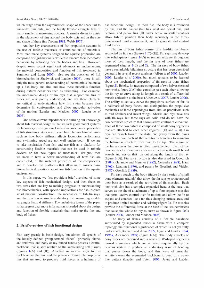
Figure 1. Overview of fish anatomy. (A) Skeleton of a perch-like bony fish showing the segmented vertebral column and the major medianfins. (B) Image of a bluegill sunfish, Lepomis macrochirus, to show the dorsal fin (with both a spiny anterior and posterior fin region withflexible fin rays), the pectoral, pelvic, and anal fins. (C) Spiny portion of the dorsal fin in a bluegill sunfish. (D) Caudal (tail) region of abluegill sunfish. (E) Close-in view of fin rays to show that each ray is composed of jointed bony segments; a thin fin membrane is presentbetween each fin ray. Red color indicates alizarin stain for bone.
1996). A considerable number of studies have been conductedon fish muscular properties, and work-loop analyses havedemonstrated how these properties change along the bodyand how power is generated by longitudinal fish musculature(Syme 2006, Johnston and Salamonski 1984, Johnston 1981,Rome et al 1992). Wave-like deformations of the fish bodywith increasing amplitude from head to tail result in theproduction of thrust which is manifested in the water as a seriesof vortices shed into the wake by the bending body (Webb1975, Lauder and Tytell 2006).
Although some important studies have provided data onthe mechanics of fish backbones (Long 1992, Long et al 1996,Long and Nipper 1996, Hebrank 1982, Porter et al 2006),the role of body musculature in modulating stiffness duringswimming and the mechanisms by which fish can alter flexuralstiffness are as yet poorly understood. Even basic features ofundulatory locomotion such as the extent to which changingflexural stiffness of the body can affect propulsion are notwell characterized (McHenry et al 1995), and we have onlya general idea of how or if fish tissue stiffness is activelycontrolled to modulate locomotor performance.
3. Mechanics of fish fin rays
In order to investigate the mechanical properties of bony fishfin rays, we performed experiments on fresh rays from bluegillsunfish (Lepomis macrochirus) under a variety of conditions(figure 4). Individual fin rays were removed from fins andeach hemitrich clamped separately in small clips attached tomicrometer actuators allowing independent displacement ofeach hemitrich as well as measurement of the force exertedto displace one hemitrich relative to the other (figure 4(A)).This arrangement also allowed us to quantify fin ray curvaturerelative to hemitrich displacement (figure 4(B)). Cantilevermeasurements of the force output at varying sites along the finray relative to force and displacement inputs at the hemitrichs(figure 4(C)), and three-point bending tests (figure 4(D)) tocalculate the fin ray Young’s modulus were also performed.Micro-CT scans of fin rays allowed calculation of the secondmoment of area along each fin ray. All results reported here arefor bluegill sunfish pectoral fin rays.
Displacing one hemitrich relative to the other generatescurvature along the length of the fin rays, and the shape
3
Smart Mater. Struct. 20 (2011) 094014 G V Lauder et al
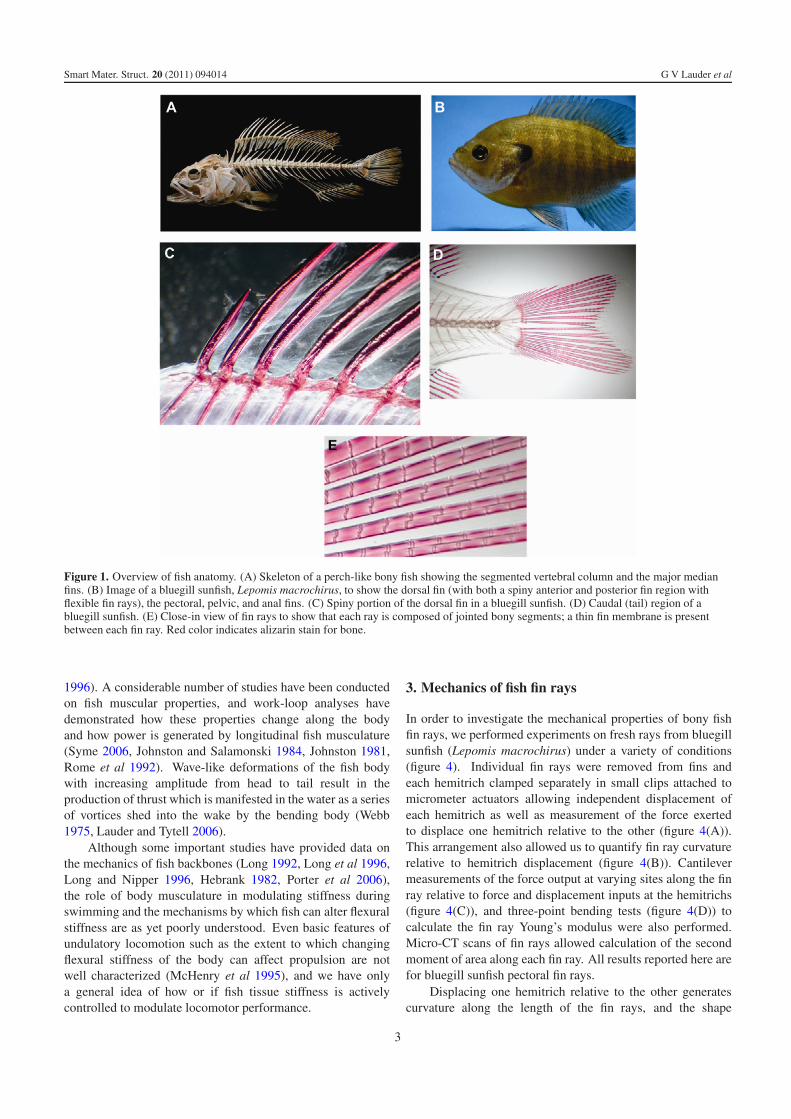
Figure 2. Schematic diagrams of ray anatomy in ray-finned fishes.(A) Lateral and dorsal views of a whole pectoral fin and two fin rays,respectively. The two hemitrichs that make up each fin ray can beseen in the dorsal view of individual fin rays. (B) Schematic diagramof the structure of an individual fin ray. Each ray has two halvescalled hemitrichs that are semilunate (shown in the raycross-section). Each hemitrich is composed of multiple bonyhemisegments. Each ray can branch one or more times along itslength. The tips of the hemitrichs are joined by fibrous actinotrichia.(C) Simplified fin ray bending mechanism. Forces are applied tohemitrichs via muscles attaching through tendons near the hemitrichbase. When the applied forces move one hemitrich relative to theother (large red arrow) to create an offset (labeled in figure) the finray bends. A ligament (green) that joins the bases of the hemitrichsslides over a supporting cartilage pad. Portions of this figuremodified from Alben et al (2007).
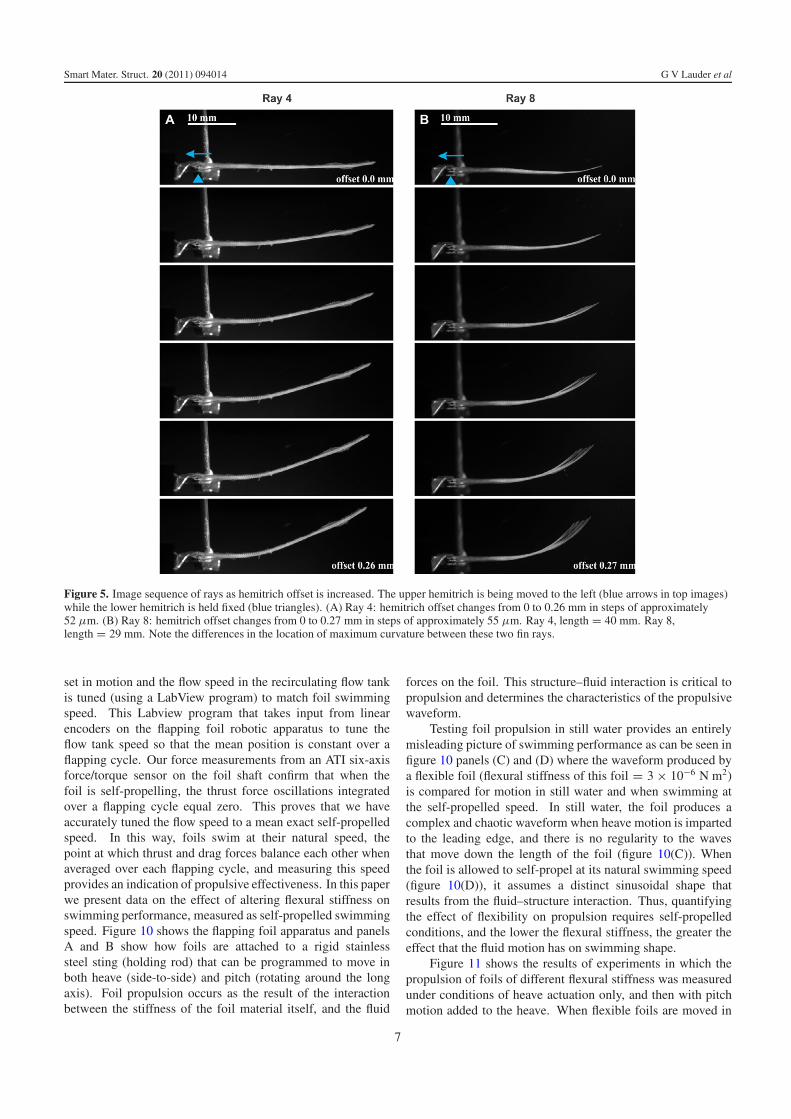
of the ray varies depending on its location within the fin(figure 5). In general, the distal and basal thirds of fin raysshow relatively little curvature, while the greatest curvature
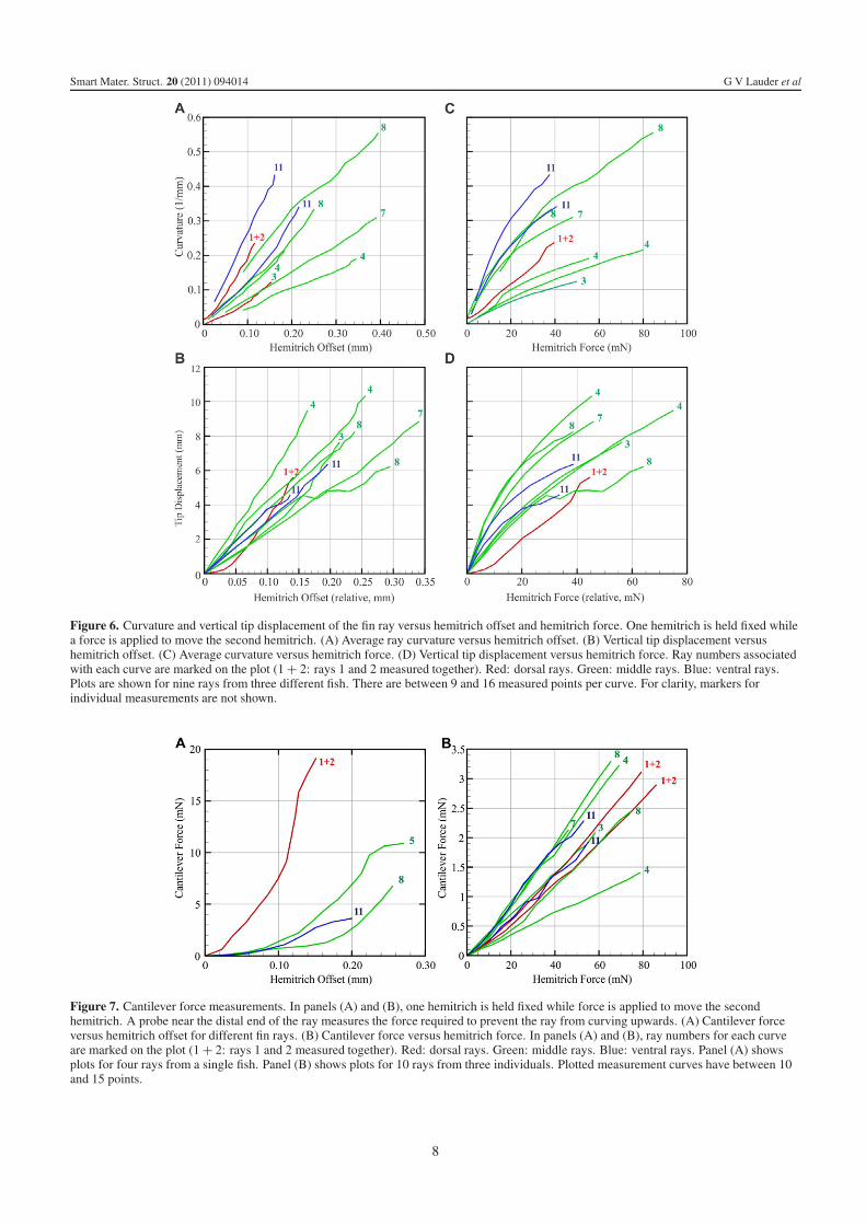
occurs in the middle region of the fin (figure 5). The maximumcurvatures of each fin ray produced by hemitrich displacementare approximately linear functions of the offset of the bases(figures 6(A) and (B)). Fin rays differ considerably in theextent of curvature for a given hemitrich base offset. Raysin the middle of the fin give curvature values of around0.3 mm−1 for a 0.2 mm displacement, and the tips of the finrays displace 5–10 mm from the centerline for an 0.2 mmoffset. These curvature values are similar to those observedin kinematic studies of the fins of swimming fishes (Standenand Lauder 2005, 2007, Taft et al 2008), and indicatethat these in vitro manipulations of fin rays produce naturaldeformations. Measurement of the force required to displacehemitrichs relative to each other show that fin rays at differentlocations within the fin differ considerably from each otherin the extent of force needed to produce a given curvatureor tip displacement (figures 6(C) and (D)): a force of 30 mNapplied to one hemitrich of the pair can generate between0.1 mm−1 and 0.4 mm−1 curvature and 3.5 mm and 8.5 mmtip displacement respectively depending on the fin ray.
Cantilever force measurements to quantify the relationshipbetween hemitrich offsets and force inputs at the hemitrichbases and output at the fin ray (method shown in figure 4(C))show that the first two fin rays (joined together tightly and thustreated as a unit) produce much more force out for a givenoffset input than the other fin rays (figure 7). A 0.15 mmoffset generates almost 20 mN force near the end of the finray for ray 1 + 2, but only 1–4 mN force for other fin rays(figure 7(A)). Simultaneous measurements of force input andoutput show that the fin ray design is not particularly effectiveat transmitting force, as a 50 mN force input only produces1.5 mN of force near the tip of the ray (figure 7(B)).
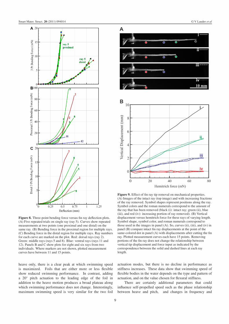
Three-point bending tests on bluegill sunfish fin rays showthat there is considerable variation between locations along thefin rays (figure 8) and that the basal region of each ray is muchstiffer than the distal (outer) region (figure 8(A)). Fin rayswithin the fin differ considerably in their force–displacementcurve with smaller rays on the ventral margin of the fin (rays11 and 12) being much less stiff than other rays in the fin.
Because fin rays are reported to possess a seriesof connections along the lengths of the two hemitrichs,and mathematical models of fin ray function indicate theimportance of these connections compared to the attachment atthe tips (Alben et al 2007) we made a series of measurementsof tip displacement versus force input for fin rays in whichwe sequentially cut the ray shorter from the tip toward thebase (figure 9). In figure 9(B), each curve ii, iii, and ivcompares intact fin ray displacements at the point of thesame-colored dot in figure 9(A) (online figure version is incolor), with displacements after cutting the fin ray. These datashow that cutting the fin ray to remove any tip connectionsand to progressively make the ray shorter does not alter thedisplacement–force plot slope as compared to an intact finray: both the dashed lines and solid lines in figure 9(B)are very similar for each fin ray length compared to thesame position in the intact ray. Shorter sections of fin raysthus show the same response to a given force input as theintact ray, indicating clearly that the two hemitrichs possess a
4
Smart Mater. Struct. 20 (2011) 094014 G V Lauder et al
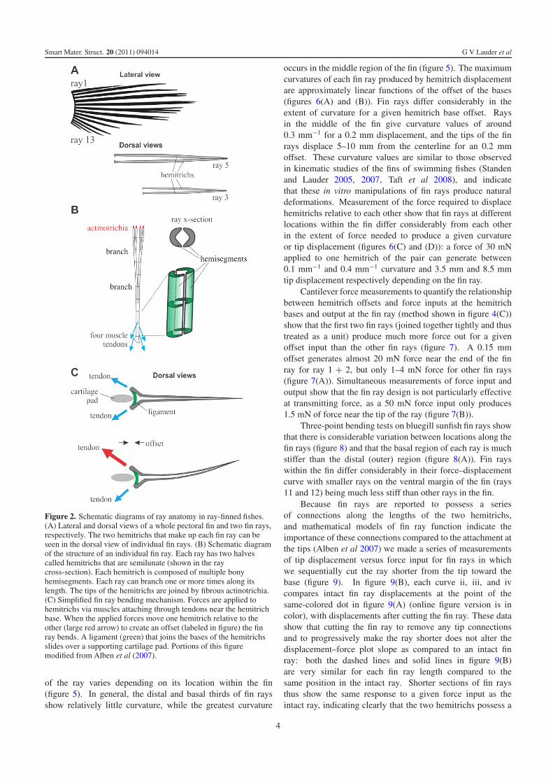
Figure 3. Three-dimensional reconstructions from micro-CT scans of fin rays and the supporting skeleton in a bluegill sunfish, with the majorelements segmented and indicated in different colors. (A) The pectoral girdle with the scapula, coracoid, and radials support the pectoral finrays. Medial hemitrichs are shown in red and lateral hemitrichs are shown in blue. (B) Most hemitrichs have two tendon attachment points.The adductor superficialis and adductor profundus pectoral fin muscles attach to the medial hemitrichs (yellow arrows). The abductorprofundus and abductor superficialis attach to the lateral hemitrichs (not shown). (C) The medial hemitrich of the first ray has a large basestructure that articulates with the coracoid. The lateral hemitrich base is much smaller. Unlike other rays, the hemitrichs of ray 1 are fusedover much of their lengths, and the bases of the two hemitrichs are asymmetrical in structure. The base of the ray 2 medial hemitrich is shownfor comparison. (D) Protrusions at the base of the hemitrichs are attachment points for muscle tendons. The ventralmost nine fin rays are eachshown in a different color, and in an oblique view down the fin from proximal to distal.
series of interconnections along their length that dominate themechanical behavior of the system. It is currently unclear justwhat the nature of the connection between the two hemitrichsof fish fin rays is, and what the material located inside thetwo semilunar hemitrichs consists of. Certainly small bloodvessels, lymphatics, and nerves may be present, but thesestructures will not bridge the two hemitrichs. There has beensome suggestion of elastic fibers connecting the two hemitrichsof a fin ray (Videler 1993, Geerlink and Videler 1987),but considerable future work will be needed to convincinglyidentify the specific components that are responsible for thebehavior of the bilaminar fin ray design.
Data from the three-point bending tests along with micro-CT scans of bluegill sunfish fin rays were used to estimatethe second moment of area of individual fin rays and also themodulus of elasticity (Young’s modulus). Table 1 shows asummary of these data and calculated values of the modulusof elasticity of different fin rays. The mean modulus for theproximal (basal) region of the fin rays was 1.34 GPa, but thisvaried from 0.24 to 3.7 for different fin rays. The distal finregion was less stiff, and moduli for the different fin rays
measured varied from 0.11 to 0.67 GPa. These data are similarto that of human tendon (modulus around 0.5 GPa), whichis not too surprising given that adjacent fin ray segments areconnected by collagenous fibers, and that bending of fin rayswould stretch these fibers. Hence, fin ray stiffness may bedominated by the same collagenous proteins found in tendons.
4. Flexible foils as models of fish propulsion
Understanding fin ray mechanics is a critical part of learningabout the material design of fishes, but a second key featureof fish design is the flexible body that is used in a wave-like undulatory fashion to power propulsion in fishes. Bodydeformations have frequently been quantified to calculatewave velocities, the amplitude of side-to-side excursionsdown the body, and locomotor efficiency (e.g. Webb 1975,1978, Webb and Keyes 1982, Lauder and Tytell 2006).Measurements of body wave characteristics have given rise tothe common terminology used to characterize different modesof undulatory locomotion in fishes, such as the anguilliform(or eel-like) pattern of body waves compared to a trout-like
5
Smart Mater. Struct. 20 (2011) 094014 G V Lauder et al
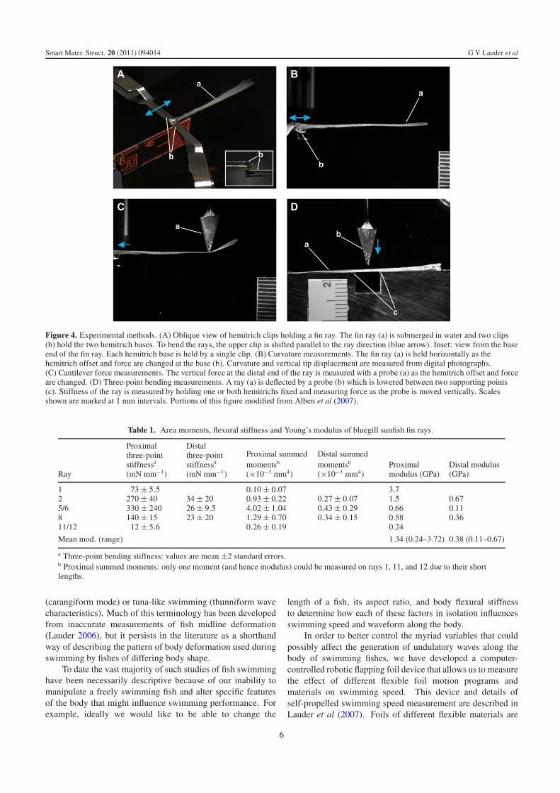
Figure 4. Experimental methods. (A) Oblique view of hemitrich clips holding a fin ray. The fin ray (a) is submerged in water and two clips(b) hold the two hemitrich bases. To bend the rays, the upper clip is shifted parallel to the ray direction (blue arrow). Inset: view from the baseend of the fin ray. Each hemitrich base is held by a single clip. (B) Curvature measurements. The fin ray (a) is held horizontally as thehemitrich offset and force are changed at the base (b). Curvature and vertical tip displacement are measured from digital photographs.(C) Cantilever force measurements. The vertical force at the distal end of the ray is measured with a probe (a) as the hemitrich offset and forceare changed. (D) Three-point bending measurements. A ray (a) is deflected by a probe (b) which is lowered between two supporting points(c). Stiffness of the ray is measured by holding one or both hemitrichs fixed and measuring force as the probe is moved vertically. Scalesshown are marked at 1 mm intervals. Portions of this figure modified from Alben et al (2007).
Table 1. Area moments, flexural stiffness and Young’s modulus of bluegill sunfish fin rays.
Ray
Proximalthree-pointstiffnessa
(mN mm−1)
Distalthree-pointstiffnessa
(mN mm−1)
Proximal summedmomentsb
(×10−3 mm4)
Distal summedmomentsb
(×10−3 mm4)Proximalmodulus (GPa)
Distal modulus(GPa)
1 73 ± 5.5 0.10 ± 0.07 3.72 270 ± 40 34 ± 20 0.93 ± 0.22 0.27 ± 0.07 1.5 0.675/6 330 ± 240 26 ± 9.5 4.02 ± 1.04 0.43 ± 0.29 0.66 0.118 140 ± 15 23 ± 20 1.29 ± 0.70 0.34 ± 0.15 0.58 0.3611/12 12 ± 5.6 0.26 ± 0.19 0.24
Mean mod. (range) 1.34 (0.24–3.72) 0.38 (0.11–0.67)
a Three-point bending stiffness: values are mean ±2 standard errors.b Proximal summed moments: only one moment (and hence modulus) could be measured on rays 1, 11, and 12 due to their shortlengths.
(carangiform mode) or tuna-like swimming (thunniform wavecharacteristics). Much of this terminology has been developedfrom inaccurate measurements of fish midline deformation(Lauder 2006), but it persists in the literature as a shorthandway of describing the pattern of body deformation used duringswimming by fishes of differing body shape.
To date the vast majority of such studies of fish swimminghave been necessarily descriptive because of our inability tomanipulate a freely swimming fish and alter specific featuresof the body that might influence swimming performance. Forexample, ideally we would like to be able to change the
length of a fish, its aspect ratio, and body flexural stiffnessto determine how each of these factors in isolation influencesswimming speed and waveform along the body.
In order to better control the myriad variables that couldpossibly affect the generation of undulatory waves along thebody of swimming fishes, we have developed a computer-controlled robotic flapping foil device that allows us to measurethe effect of different flexible foil motion programs andmaterials on swimming speed. This device and details ofself-propelled swimming speed measurement are described inLauder et al (2007). Foils of different flexible materials are
6
Smart Mater. Struct. 20 (2011) 094014 G V Lauder et al
Figure 5. Image sequence of rays as hemitrich offset is increased. The upper hemitrich is being moved to the left (blue arrows in top images)while the lower hemitrich is held fixed (blue triangles). (A) Ray 4: hemitrich offset changes from 0 to 0.26 mm in steps of approximately52 µm. (B) Ray 8: hemitrich offset changes from 0 to 0.27 mm in steps of approximately 55 µm. Ray 4, length = 40 mm. Ray 8,length = 29 mm. Note the differences in the location of maximum curvature between these two fin rays.
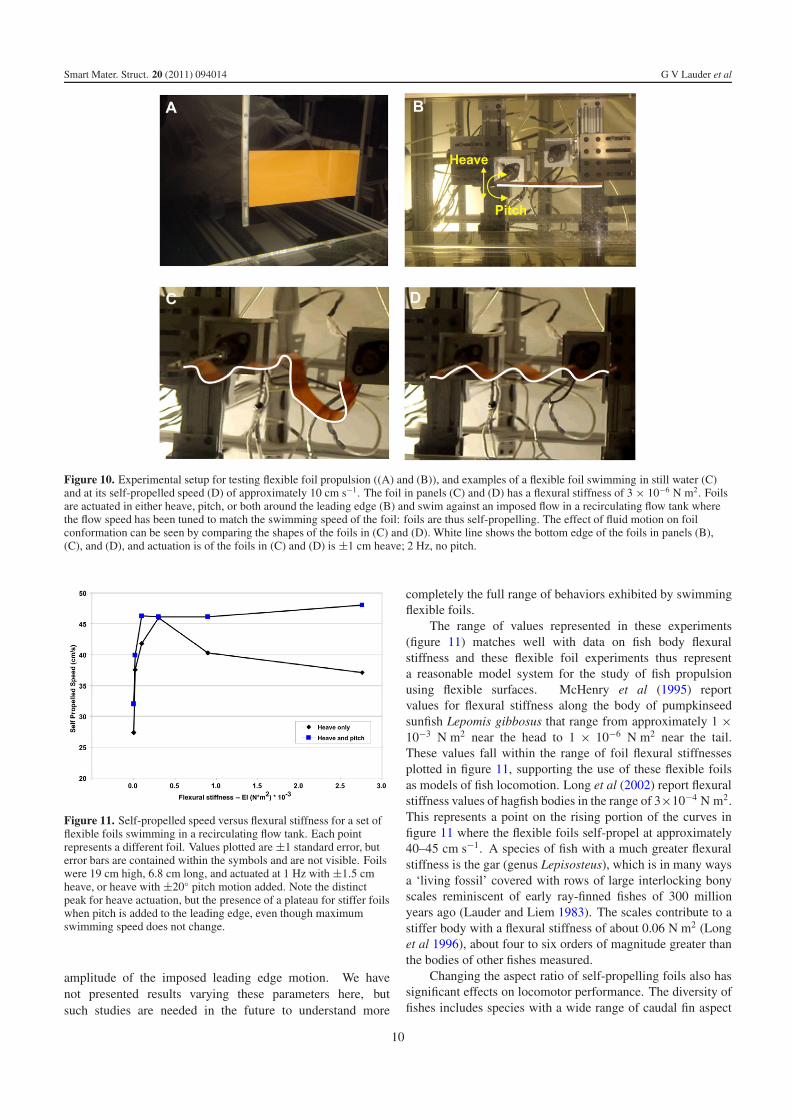
set in motion and the flow speed in the recirculating flow tankis tuned (using a LabView program) to match foil swimmingspeed. This Labview program that takes input from linearencoders on the flapping foil robotic apparatus to tune theflow tank speed so that the mean position is constant over aflapping cycle. Our force measurements from an ATI six-axisforce/torque sensor on the foil shaft confirm that when thefoil is self-propelling, the thrust force oscillations integratedover a flapping cycle equal zero. This proves that we haveaccurately tuned the flow speed to a mean exact self-propelledspeed. In this way, foils swim at their natural speed, thepoint at which thrust and drag forces balance each other whenaveraged over each flapping cycle, and measuring this speedprovides an indication of propulsive effectiveness. In this paperwe present data on the effect of altering flexural stiffness onswimming performance, measured as self-propelled swimmingspeed. Figure 10 shows the flapping foil apparatus and panelsA and B show how foils are attached to a rigid stainlesssteel sting (holding rod) that can be programmed to move inboth heave (side-to-side) and pitch (rotating around the longaxis). Foil propulsion occurs as the result of the interactionbetween the stiffness of the foil material itself, and the fluid
forces on the foil. This structure–fluid interaction is critical topropulsion and determines the characteristics of the propulsivewaveform.
Testing foil propulsion in still water provides an entirelymisleading picture of swimming performance as can be seen infigure 10 panels (C) and (D) where the waveform produced bya flexible foil (flexural stiffness of this foil = 3 × 10⁻⁶ N m2)is compared for motion in still water and when swimming atthe self-propelled speed. In still water, the foil produces acomplex and chaotic waveform when heave motion is impartedto the leading edge, and there is no regularity to the wavesthat move down the length of the foil (figure 10(C)). Whenthe foil is allowed to self-propel at its natural swimming speed(figure 10(D)), it assumes a distinct sinusoidal shape thatresults from the fluid–structure interaction. Thus, quantifyingthe effect of flexibility on propulsion requires self-propelledconditions, and the lower the flexural stiffness, the greater theeffect that the fluid motion has on swimming shape.
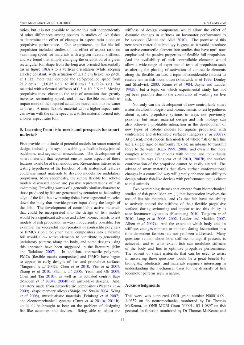
Figure 11 shows the results of experiments in which thepropulsion of foils of different flexural stiffness was measuredunder conditions of heave actuation only, and then with pitchmotion added to the heave. When flexible foils are moved in
7
Smart Mater. Struct. 20 (2011) 094014 G V Lauder et al
Figure 6. Curvature and vertical tip displacement of the fin ray versus hemitrich offset and hemitrich force. One hemitrich is held fixed whilea force is applied to move the second hemitrich. (A) Average ray curvature versus hemitrich offset. (B) Vertical tip displacement versushemitrich offset. (C) Average curvature versus hemitrich force. (D) Vertical tip displacement versus hemitrich force. Ray numbers associatedwith each curve are marked on the plot (1 + 2: rays 1 and 2 measured together). Red: dorsal rays. Green: middle rays. Blue: ventral rays.Plots are shown for nine rays from three different fish. There are between 9 and 16 measured points per curve. For clarity, markers forindividual measurements are not shown.
Figure 7. Cantilever force measurements. In panels (A) and (B), one hemitrich is held fixed while force is applied to move the secondhemitrich. A probe near the distal end of the ray measures the force required to prevent the ray from curving upwards. (A) Cantilever forceversus hemitrich offset for different fin rays. (B) Cantilever force versus hemitrich force. In panels (A) and (B), ray numbers for each curveare marked on the plot (1 + 2: rays 1 and 2 measured together). Red: dorsal rays. Green: middle rays. Blue: ventral rays. Panel (A) showsplots for four rays from a single fish. Panel (B) shows plots for 10 rays from three individuals. Plotted measurement curves have between 10and 15 points.
8
Smart Mater. Struct. 20 (2011) 094014 G V Lauder et al
Figure 8. Three-point bending force versus fin ray deflection plots.(A) Five repeated trials on single ray (ray 5). Curves show repeatedmeasurements at two points (one proximal and one distal) on thesame ray. (B) Bending force in the proximal region for multiple rays.(C) Bending force in the distal region for multiple rays. Ray numbersfor each curve are marked on the plot. Red: dorsal rays (ray 2).Green: middle rays (rays 5 and 8). Blue: ventral rays (rays 11 and12). Panels B and C show plots for eight and six rays from twoindividuals. Where markers are not shown, plotted measurementcurves have between 11 and 15 points.
heave only, there is a clear peak at which swimming speedis maximized. Foils that are either more or less flexibleshow reduced swimming performance. In contrast, addinga 20◦ pitch actuation to the leading edge of the foil inaddition to the heave motion produces a broad plateau alongwhich swimming performance does not change. Interestingly,maximum swimming speed is very similar for the two foil
Figure 9. Effect of fin ray tip removal on mechanical properties.(A) Images of the intact ray (top image) and with increasing fractionsof the ray removed. Symbol shapes represent positions along the ray.Symbol colors and the roman numerals correspond to the amount ofthe ray that has been removed (black (i): intact ray; green (ii), blue(iii), and red (iv): increasing portion of ray removed). (B) Verticaldisplacement versus hemitrich force for these rays of varying length.Symbol shape, symbol color, and roman numerals correspond tothose used in the images in panel (A). So, curves (ii), (iii), and (iv) inpanel (B) compare intact fin ray displacements at the point of thesame-colored dot in panel (A) with displacements after cutting the finray. Plotted measurement curves each have 15 points. Removingportions of the fin ray does not change the relationship betweenvertical tip displacement and force input as indicated by thecorrespondence between the solid and dashed lines at each raylength.
actuation modes, but there is no decline in performance asstiffness increases. These data show that swimming speed offlexible bodies in the water depends on the type and pattern ofactuation, and on the value chosen for flexural stiffness.
There are certainly additional parameters that couldinfluence self-propelled speed such as the phase relationshipbetween heave and pitch, and changes in frequency and
9
Smart Mater. Struct. 20 (2011) 094014 G V Lauder et al
Figure 10. Experimental setup for testing flexible foil propulsion ((A) and (B)), and examples of a flexible foil swimming in still water (C)and at its self-propelled speed (D) of approximately 10 cm s−1. The foil in panels (C) and (D) has a flexural stiffness of 3 × 10⁻⁶ N m2. Foilsare actuated in either heave, pitch, or both around the leading edge (B) and swim against an imposed flow in a recirculating flow tank wherethe flow speed has been tuned to match the swimming speed of the foil: foils are thus self-propelling. The effect of fluid motion on foilconformation can be seen by comparing the shapes of the foils in (C) and (D). White line shows the bottom edge of the foils in panels (B),(C), and (D), and actuation is of the foils in (C) and (D) is ±1 cm heave; 2 Hz, no pitch.
Figure 11. Self-propelled speed versus flexural stiffness for a set offlexible foils swimming in a recirculating flow tank. Each pointrepresents a different foil. Values plotted are ±1 standard error, buterror bars are contained within the symbols and are not visible. Foilswere 19 cm high, 6.8 cm long, and actuated at 1 Hz with ±1.5 cmheave, or heave with ±20◦ pitch motion added. Note the distinctpeak for heave actuation, but the presence of a plateau for stiffer foilswhen pitch is added to the leading edge, even though maximumswimming speed does not change.
amplitude of the imposed leading edge motion. We havenot presented results varying these parameters here, butsuch studies are needed in the future to understand more
completely the full range of behaviors exhibited by swimmingflexible foils.
The range of values represented in these experiments(figure 11) matches well with data on fish body flexuralstiffness and these flexible foil experiments thus representa reasonable model system for the study of fish propulsionusing flexible surfaces. McHenry et al (1995) reportvalues for flexural stiffness along the body of pumpkinseedsunfish Lepomis gibbosus that range from approximately 1 ×10⁻³ N m2 near the head to 1 × 10⁻⁶ N m2 near the tail.These values fall within the range of foil flexural stiffnessesplotted in figure 11, supporting the use of these flexible foilsas models of fish locomotion. Long et al (2002) report flexuralstiffness values of hagfish bodies in the range of 3×10⁻⁴ N m2.This represents a point on the rising portion of the curves infigure 11 where the flexible foils self-propel at approximately40–45 cm s−1. A species of fish with a much greater flexuralstiffness is the gar (genus Lepisosteus), which is in many waysa ‘living fossil’ covered with rows of large interlocking bonyscales reminiscent of early ray-finned fishes of 300 millionyears ago (Lauder and Liem 1983). The scales contribute to astiffer body with a flexural stiffness of about 0.06 N m2 (Longet al 1996), about four to six orders of magnitude greater thanthe bodies of other fishes measured.
Changing the aspect ratio of self-propelling foils also hassignificant effects on locomotor performance. The diversity offishes includes species with a wide range of caudal fin aspect
10
Smart Mater. Struct. 20 (2011) 094014 G V Lauder et al
ratios, but it is not possible to isolate this trait independentlyof other differences among species in studies of live fishesto determine the effect of changes in aspect ratio alone onpropulsive performance. Our experiments on flexible foilpropulsion included studies of the effect of aspect ratio onswimming speed for materials with a given flexural stiffness,and we found that simply changing the orientation of a givenrectangular foil shape from the long axis oriented horizontally(as in figure 10(A)) to a vertical orientation (while keepingall else constant, with actuation of ±1.5 cm heave, no pitch,at 1 Hz) more than doubled the self-propelled speed from21.2 cm s−1 (±0.85 s.e.) to 46.0 cm s−1 (±0.24 s.e.) formaterial with a flexural stiffness of 0.3 × 10⁻³ N m2. Movingpropulsive mass closer to the axis of actuation thus greatlyincreases swimming speed, and allows flexible materials toimpart more of the imposed actuation movement into the wateras thrust. A more flexible material with a higher aspect ratiocan swim with the same speed as a stiffer material formed intoa lower aspect ratio foil.
5. Learning from fish: needs and prospects for smartmaterials
Fish provide a multitude of potential models for smart materialdesign, including fin rays, fin webbing, a flexible body, jointedbackbone, and segmental musculature. The development ofsmart materials that represent one or more aspects of thesefeatures would be of tremendous use. Researchers interested intesting hypotheses of the function of fish anatomical featurescould use smart materials to develop models for undulatorypropulsion. More specifically, the simple flexible foil roboticmodels discussed above are passive representations of fishswimming. Traveling waves of a generally similar character tothose produced by fish are generated by actuation at the leadingedge of the foil, but swimming fishes have segmental musclesdown the body that provide power input along the length ofthe fish. The development of controllable active materialsthat could be incorporated into the design of fish modelswould be a significant advance and allow biomechanists to testmodels of fish propulsion in ways not currently possible. Forexample, the successful incorporation of contractile polymersor IPMCs (ionic polymer metal composites) into a flexiblefoil would allow active elements to contribute to generatingundulatory patterns along the body, and some designs usingthis approach have been suggested in the literature (Kimand Tadokoro 2007). In addition, contractile polymers,FMCs (flexible matrix composites) and IPMCs have begunto appear in early designs of fins and propulsive surfaces(Tangorra et al 2007a, Chen et al 2010, Yim et al 2007,Zhang et al 2010, Shan et al 2006, Yeom and Oh 2009,Chen and Tan 2010), as well as in actuated control flaps(Madden et al 2004a, 2004b) on airfoil-like designs. And,actuators made from peizoelectric composites (Wiguna et al2009), shape memory alloys (Shinjo and Swain 2004, Wanget al 2008), muscle-tissue materials (Feinberg et al 2007),and electromechanical systems (Curet et al 2011a, 2011b),could all be brought to bear on the problem of designingfish-like actuators and devices. Being able to adjust the
stiffness of design components would allow the effect ofdynamic changes in stiffness on locomotor performance tobe assessed (Mutlu and Alici 2010). The promise of thisnew smart material technology is great, as it would introducean active contractile element into studies that have until nowemphasized the passive properties of flexible foil propulsion.And the availability of such controllable elements wouldallow a wide range of experimental tests of propulsion suchas altering the phasing of activation of contractile elementsalong the flexible surface, a topic of considerable interest toresearchers in fish locomotion (Shadwick et al 1999, Donleyand Shadwick 2003, Rome et al 1984, Jayne and Lauder1995b), but a topic on which experimental study has notyet been possible due to the constraints of working on livefish.
Not only can the development of new controllable smartmaterials allow biologists and biomechanists to test hypothesesabout aquatic propulsive systems in ways not previouslypossible, but smart material design and fish biology canalso achieve a profitable interaction in the development ofnew types of robotic models for aquatic propulsion withcontrollable and deformable surfaces (Tangorra et al 2007a).At present, most robotic fish models of whole fish or fish finsuse a single rigid or uniformly flexible membrane to transmitforce to the water (Kato 1999, 2000), and even in the morecomplex robotic fish models with jointed and individuallyactuated fin rays (Tangorra et al 2010, 2007b) the surfaceconformation of the propulsor cannot be easily altered. Theadvent of smart materials that allow surface conformationalchanges in a controlled way will greatly enhance our ability todesign robotic fish-like devices with performance that is closerto real animals.
Two overarching themes that emerge from biomechanicalstudies of fish propulsion are (1) that locomotion involves theuse of flexible materials, and (2) that fish have the abilityto actively control the stiffness of their flexible propulsivesurfaces during swimming and appear to use this ability totune locomotor dynamics (Flammang 2010, Tangorra et al2010, Long et al 2006, 2002, Lauder and Madden 2007,Alben et al 2007). And the extent to which body and finstiffness changes moment-to-moment during locomotion in atime-dependent fashion has not yet been addressed. Manyquestions remain about how stiffness tuning, if present, isachieved, and to what extent fish can modulate stiffnessof the body and fins to optimize propulsive performance.The advent of smart materials that can be used to assistin answering these questions would be a great benefit forbiologists, roboticists, and materials engineers interesting inunderstanding the mechanical basis for the diversity of fishlocomotor patterns seen in nature.
Acknowledgments
This work was supported ONR grant number N00014-09-1-0352 on fin neuromechanics monitored by Dr ThomasMcKenna, an ONR-MURI Grant N00014-03-1-0897 on fishpectoral fin function monitored by Dr Thomas McKenna and
11
Smart Mater. Struct. 20 (2011) 094014 G V Lauder et al
initiated by Dr Promode Bandyopadhyay, and by NSF EFRI-0938043. We thank members of the Lauder and Tangorra Labsfor many helpful discussions on fish fins and flexible flappingfoil propulsion.
References
Alben S, Madden P G A and Lauder G V 2007 The mechanics ofactive fin-shape control in ray-finned fishes J. R. Soc. Interface4 243–56
Alexander R M 1969 The orientation of muscle fibers in themyomeres of fishes J. Mar. Biol. Assoc. UK 49 263–90
Brainerd E L and Azizi E 2005 Muscle fiber angle, segment bulgingand architectural gear ratio in segmented musculature J. Exp.Biol. 208 3249–61
Chen Z, Shatara S and Tan X 2010 Modeling of biomimetic roboticfish propelled by an ionic polymer–metal composite caudal finIEEE Trans. Mechatron. 15 448–59
Chen Z and Tan X 2010 Monolithic fabrication of ionicpolymer–metal composite actuators capable of complexdeformation Sensors Actuators A 157 246–57
Curet O M, Patankar N A, Lauder G V and MacIver M A 2011aAquatic manoeuvering with counter-propagating waves: a novellocomotive strategy J. R. Soc. Interfacedoi:10.1098/rsif.2010.0493
Curet O M, Patankar N A, Lauder G V and MacIver M A 2011bMechanical properties of a bio-inspired robotic knifefish withan undulatory propulsor Bioinsp. Biomimet. 6 026004
Donley J and Shadwick R 2003 Steady swimming muscle dynamicsin the leopard shark Triakis semifasciata J. Exp. Biol.206 1117–26
Feinberg A W, Feigel A, Shevkoplyas S S, Sheehy S,Whitesides G M and Parker K K 2007 Muscular thin films forbuilding actuators and powering devices Science 317 1366–70
Flammang B E 2010 Functional morphology of the radialis muscle inshark tails J. Morphol. 271 340–52
Geerlink P J 1989 Pectoral fin morphology: a simple relation withmovement pattern? Neth. J. Zool. 39 166–93
Geerlink P J and Videler J J 1987 The relation between structure andbending properties of teleost fin rays Neth. J. Zool. 37 59–80
Geraudie J 1988 Fine structural peculiarities of the pectoral findermoskeleton of two Brachiopterygii, Polypterus senegalusand Calamoichthys calabarisus (Pisces, Osteichthyes) Anat.Rec. 221 455–68
Geraudie J and Meunier F 1982 Comparative fine structure of theosteichthyan dermotrichia Anat. Rec. 202 325–8
Goodrich E S 1904 On the dermal fin-rays of fishes, living andextinct Q. J. Microsc. Sci. 47 465–522
Haas H J 1962 Studies on mechanisms of joint and bone formation inthe skeletal rays of fish fins Dev. Biol. 5 1–34
Hebrank M R 1982 Mechanical properties of fish backbones inlateral bending and in tension J. Biomech. 15 85–9
Helfman G S, Collette B B and Facey D E 1997 The Diversity ofFishes (Malden, MA: Blackwell Science)
Jayne B C and Lauder G V 1994 Comparative morphology of themyomeres and axial skeleton in four genera of centrarchidfishes J. Morphol. 220 185–205
Jayne B C and Lauder G V 1995a Are muscle fibers within fishmyotomes activated synchronously? Patterns of recruitmentwithin deep myomeric musculature during swimming inlargemouth bass J. Exp. Biol. 198 805–15
Jayne B C and Lauder G V 1995b Red muscle motor patterns duringsteady swimming in largemouth bass: effects of speed andcorrelations with axial kinematics J. Exp. Biol. 198 1575–87
Jayne B C and Lauder G V 1996 New data on axial locomotion infishes: how speed affects diversity of kinematics and motorpatterns Am. Zool. 36 642–55
Johnston I A 1981 Structure and function in fish muscle Symp. of theZoological Society of London vol 84, pp 71–113
Johnston I A and Salamonski J 1984 Power output and force-velocityrelationship of red and white muscle fibres from the pacific bluemarlin (Makaira nigricans) J. Exp. Biol. 111 171–7
Kato N 1999 Hydrodynamic characteristics of a mechanical pectoralfin J. Fluids Eng. 121 605–13
Kato N 2000 Control performance in the horizontal plane of a fishrobot with mechanical pectoral fins IEEE J. Ocean. Eng.25 121–9
Kim K and Tadokoro S (ed) 2007 Electroactive Polymers for RoboticApplications (Berlin: Springer)
Lanzing W J R 1976 The fine structure of fins and finrays of Tilapiamossambica (Peters) Cell Tissue Res. 173 349–56
Lauder G V 2006 Locomotion The Physiology of Fishes 3rd edn,ed D H Evans and J B Claiborne (Boca Raton, FL: CRC Press)pp 3–46
Lauder G V, Anderson E J, Tangorra J and Madden P G 2007 Fishbiorobotics: kinematics and hydrodynamics of self-propulsionJ. Exp. Biol. 210 2767–80
Lauder G V and Liem K F 1983 The evolution and interrelationshipsof the actinopterygian fishes Bull. Mus. Comp. Zool. Harv. 15095–197
Lauder G V and Madden P G A 2006 Learning from fish: kinematicsand experimental hydrodynamics for roboticists Int. J. Automat.Comput. 4 325–35
Lauder G V and Madden P G A 2007 Fish locomotion: kinematicsand hydrodynamics of flexible foil-like fins Exp. Fluids43 641–53
Lauder G V, Madden P G A, Mittal R, Dong H andBozkurttas M 2006 Locomotion with flexible propulsors I:experimental analysis of pectoral fin swimming in sunfishBioinsp. Biomimet. 1 S25–34
Lauder G V and Tytell E D 2006 Hydrodynamics of undulatorypropulsion Fish Biomechanics vol 23 Fish Physiologyed R E Shadwick and G V Lauder (San Diego, CA: Academic)pp 425–68
Long J H 1992 Stiffness and damping forces in the intervertebraljoints of blue marlin (Makaira nigricans) J. Exp. Biol. 162131–55
Long J H, Hale M, McHenry M and Westneat M 1996 Functions offish skin: flexural stiffness and steady swimming of longnosegar Lepisosteus osseus J. Exp. Biol. 199 2139–51
Long J, Koob-Emunds M, Sinwell B and Koob T J 2002 Thenotochord of hagfish Myxine glutinosa: visco-elastic propertiesand mechanical functions during steady swimming J. Exp. Biol.205 3819–31
Long J H, Koob T J Jr, Irving K, Combie K, Engel V, Livingston N,Lammert A and Schumacher J 2006 Biomimetic evolutionaryanalysis: testing the adaptive value of vertebrate tail stiffness inautonomous swimming robots J. Exp. Biol. 209 4732–46
Long J H and Nipper K S 1996 The importance of body stiffness inundulatory propulsion Am. Zool. 36 678–94
Madden J, Vandesteef N A, Anquetil P, Madden P, Takshi A,Pytel R, Lafontaine S, Wieringa P A and Hunter I W 2004aArtificial muscle technology: physical principles and navalprospects IEEE J. Ocean. Eng. 29 706–28
Madden P, Madden J, Anquetil P, Vandesteef N A and Hunter I W2004b The relation of conducting polymer actuator materialproperties to performance IEEE J. Ocean. Eng. 29 696–705
Marshall N B 1971 Explorations in the Life of Fishes (Cambridge,MA: Harvard University Press)
McHenry M J, Pell C A and Long J A 1995 Mechanical control ofswimming speed: stiffness and axial wave form in undulatingfish models J. Exp. Biol. 198 2293–305
Mutlu R and Alici G 2010 Artificial muscles with adjustable stiffnessSmart Mater. Struct. 19 045004
12
Smart Mater. Struct. 20 (2011) 094014 G V Lauder et al
Porter M E, Beltran J L, Koob T J and Summers A P 2006 Materialproperties and biochemical composition of mineralizedvertebral cartilage in seven elasmobranch species(chondrichthyes) J. Exp. Biol. 209 2920–8
Rome L, Loughna P T and Goldspink G 1984 Muscle fiber activity incarp as a function of swimming speed and muscle temperatureAm. J. Physiol. 247 R272–9
Rome L C, Choi I, Lutz G and Sosnicki A 1992 The influence oftemperature on muscle function in the fast-swimming scup. I.Shortening velocity and muscle recruitment during swimmingJ. Exp. Biol. 163 259–79
Shadwick R E, Katz S L, Korsmeyer K E, Knower T andCovell J W 1999 Muscle dynamics in skipjack tuna: timing ofred muscle shortening in relation to activation and bodycurvature during steady swimming J. Exp. Biol. 202 2139–50
Shadwick R E and Lauder G V (ed) 2006 Fish Biomechanics vol 23(San Diego, CA: Academic)
Shan Y, Philen M, Bakis C, Wang K and Rahn C 2006Nonlinear-elastic finite axisymmetric deformation of flexiblematrix composite membranes under internal pressure and axialforce Compos. Sci. Technol. 66 3053–63
Shinjo N and Swain G W 2004 Use of a shape memory alloy for thedesign of an oscillatory propulsion system IEEE J. Ocean. Eng.29 750–5
Standen E M and Lauder G V 2005 Dorsal and anal fin function inbluegill sunfish (Lepomis macrochirus): three-dimensionalkinematics during propulsion and maneuvering J. Exp. Biol.205 2753–63
Standen E M and Lauder G V 2007 Hydrodynamic function of dorsaland anal fins in brook trout (Salvelinus fontinalis) J. Exp. Biol.210 325–39
Summers A and Long J 2006 Skin and bones, sinew and gristle: themechanical behavior of fish skeletal tissues Fish Biomechanicsvol 23 Fish Physiology ed R E Shadwick and G V Lauder(San Diego, CA: Academic) pp 141–77
Syme D A 2006 Functional properties of skeletal muscle FishBiomechanics vol 23 Fish Physiology ed R E Shadwick andG V Lauder (San Diego, CA: Academic) pp 179–240
Taft N, Lauder G V and Madden P G 2008 Functional regionalizationof the pectoral fin of the benthic longhorn sculpin during stationholding and swimming J. Zool. Lond. 276 159–67
Tangorra J, Anquetil P, Fofonoff T, Chen A, Del Zio M andHunter I 2007a The application of conducting polymers to abiorobotic fin propulsor Bioinsp. Biomimet. 2 S6–17
Tangorra J L, Davidson S N, Hunter I W, Madden P G A,Lauder G V, Dong H, Bozkurttas M and Mittal R 2007b Thedevelopment of a biologically inspired propulsor for unmannedunderwater vehicles IEEE J. Ocean. Eng. 32 533–50
Tangorra J L, Lauder G V, Hunter I, Mittal R, Madden P G andBozkurttas M 2010 The effect of fin ray flexural rigidity on thepropulsive forces generated by a biorobotic fish pectoral finJ. Exp. Biol. 213 4043–54
Videler J J 1993 Fish Swimming (New York: Chapman and Hall)Wang Z, Hang G, Wang Y, Li J and Du W 2008 Embedded sma wire
actuated biomimetic fun: a module for biomimetic underwaterpropulsion Smart Mater. Struct. 17 025039
Webb P W 1975 Hydrodynamics and energetics of fish propulsionBull. Fish Res. Board Can. 190 1–159
Webb P W 1978 Hydrodynamics: nonscombroid fish FishPhysiology vol VII Locomotion ed W S Hoar andD J Randall (New York: Academic) pp 189–237
Webb P W and Keyes R S 1982 Swimming kinematics of sharksFish. Bull. 80 803–12
Wiguna T, Heo S, Park H C and Goo N S 2009 Design andexperimental parameteric study of a fish robot actuated bypiezoelectric actuators J. Intell. Mater. Syst. Struct. 20 751–7
Yeom S-W and Oh I-K 2009 A biomimetic jellyfish robot based onionic polymer metal composite actuators Smart Mater. Struct.18 085002
Yim W, Lee J and Kim K J 2007 An artificial muscle actuator forbiomimetic underwater propulsors Bioinsp. Biomimet. 2 S32–41
Young J Z 1981 The Life of Vertebrates (Oxford: Oxford UniversityPress)
Zhang Z, Philen M and Neu W 2010 A biologically inspired artificialfish using flexible matrix composite actuators: analysis andexperiment Smart Mater. Struct. 19 094017
13