BIBLIOGRAFIA de referencia
49
BIBLIOGRAFIA de referencia • Bernard J. Hamrock, Elementos de máquinas. Ed. Mc Graw Hill. • Robert L. Norton, Diseño de máquinas. Ed. Prentice Hall. • Shigley, Diseño en Ingeniería Mecánica, Ed. Mc Graw-Hill
description
Bernard J. Hamrock , Elementos de máquinas. Ed. Mc Graw Hill. Robert L. Norton , Diseño de máquinas. Ed. Prentice Hall. Shigley , Diseño en Ingeniería Mecánica, Ed. Mc Graw-Hill. BIBLIOGRAFIA de referencia. Load, Stress and Strain. When I am working on a problem, I never think - PowerPoint PPT Presentation
Transcript of BIBLIOGRAFIA de referencia
BIBLIOGRAFIAde referencia
• Bernard J. Hamrock, Elementos de máquinas. Ed. Mc Graw Hill.
• Robert L. Norton, Diseño de máquinas. Ed. Prentice Hall.
• Shigley, Diseño en Ingeniería Mecánica, Ed. Mc Graw-Hill
Load, Stress and Strain
When I am working on a problem, I never thinkabout beauty. I only think of how to solve theproblem. But when I have finished, if the solutionis not beautiful, I know it is wrong.
Richard Buckminster Fuller
Image: A dragline lifts a large load in a mining operation.
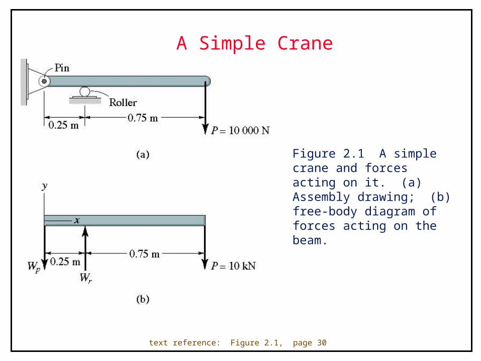
A Simple Crane
Figure 2.1 A simple crane and forces acting on it. (a) Assembly drawing; (b) free-body diagram of forces acting on the beam.
text reference: Figure 2.1, page 30
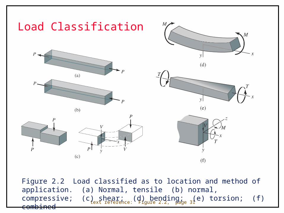
Load Classification
text reference: Figure 2.2, page 31
Figure 2.2 Load classified as to location and method of application. (a) Normal, tensile (b) normal, compressive; (c) shear; (d) bending; (e) torsion; (f) combined

Sign Convention
Figure 2.3 Sign convention used in bending. (a) y coordinate upward; (b) y coordinate downward.
text reference: Figure 2.3, page 32
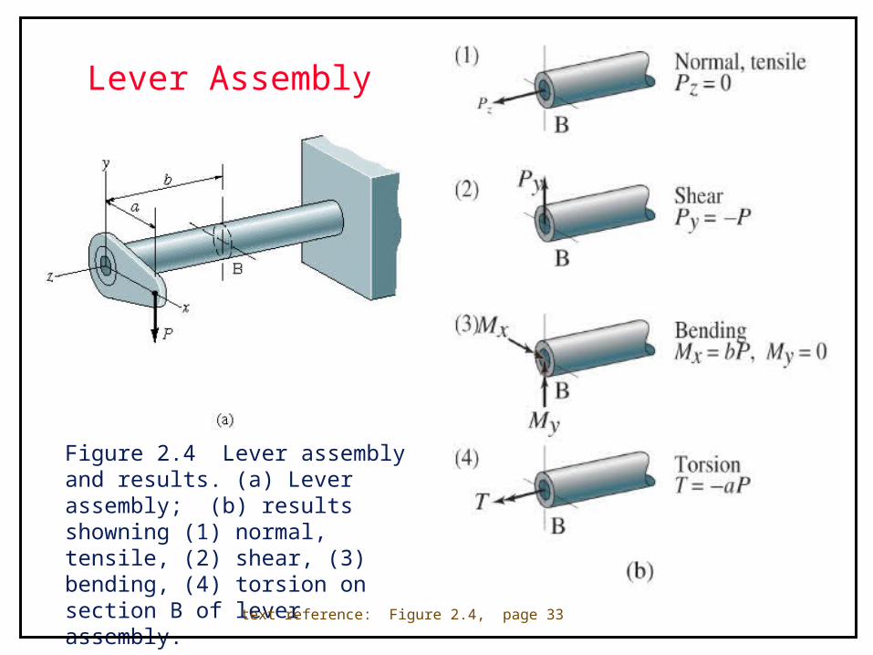
Lever Assembly
Figure 2.4 Lever assembly and results. (a) Lever assembly; (b) results showning (1) normal, tensile, (2) shear, (3) bending, (4) torsion on section B of lever assembly.
text reference: Figure 2.4, page 33
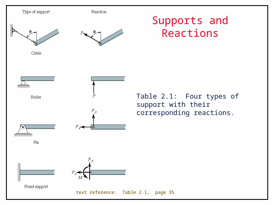
Supports and Reactions
Table 2.1: Four types of support with their corresponding reactions.
text reference: Table 2.1, page 35
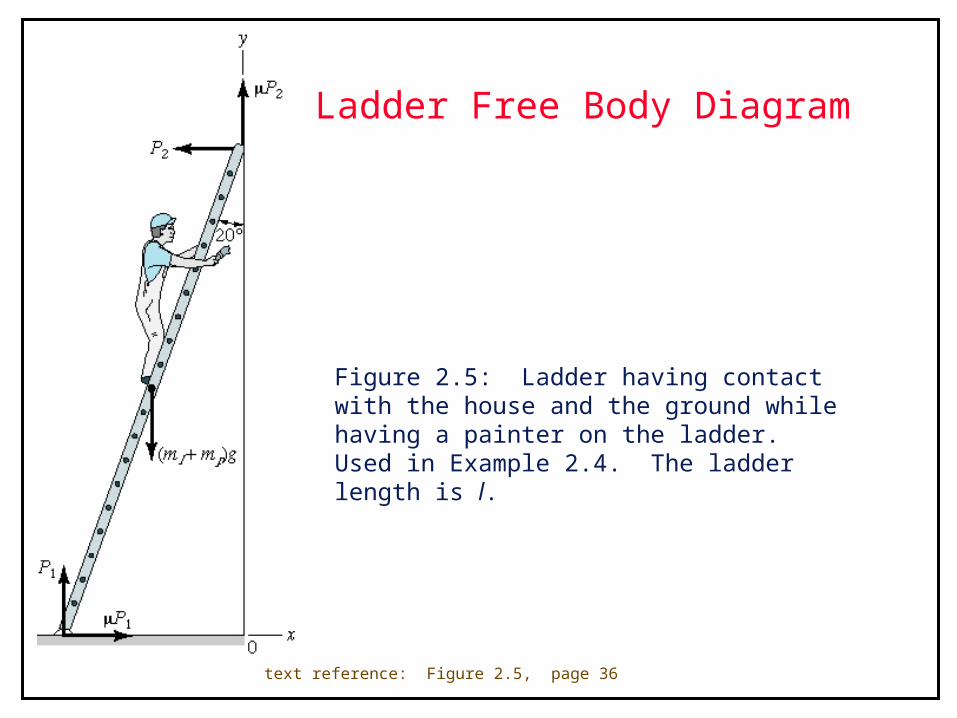
Ladder Free Body Diagram
Figure 2.5: Ladder having contact with the house and the ground while having a painter on the ladder. Used in Example 2.4. The ladder length is l.
text reference: Figure 2.5, page 36
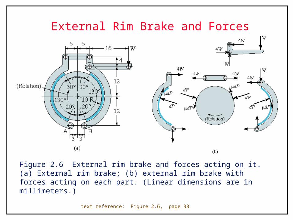
External Rim Brake and Forces
Figure 2.6 External rim brake and forces acting on it. (a) External rim brake; (b) external rim brake with forces acting on each part. (Linear dimensions are in millimeters.)
text reference: Figure 2.6, page 38
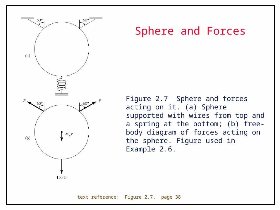
Sphere and Forces
Figure 2.7 Sphere and forces acting on it. (a) Sphere supported with wires from top and a spring at the bottom; (b) free-body diagram of forces acting on the sphere. Figure used in Example 2.6.
text reference: Figure 2.7, page 38

Beam Supports
Figure 2.8 Three types of beam support. (a) Simply supported; (b) cantilevered; (c) overhanging.
text reference: Figure 2.8, page 39

Simply Supported Bar
Figure 2.9 Simply supported bar with (a) midlength load and reactions; (b) free-body diagram for 0<x<l/2; (c) free body diagram for l/2<x<l; (d) shear and bending moment diagrams.
text reference: Figure 2.9, page 40
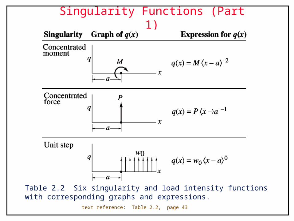
Singularity Functions (Part 1)
Table 2.2 Six singularity and load intensity functions with corresponding graphs and expressions.
text reference: Table 2.2, page 43
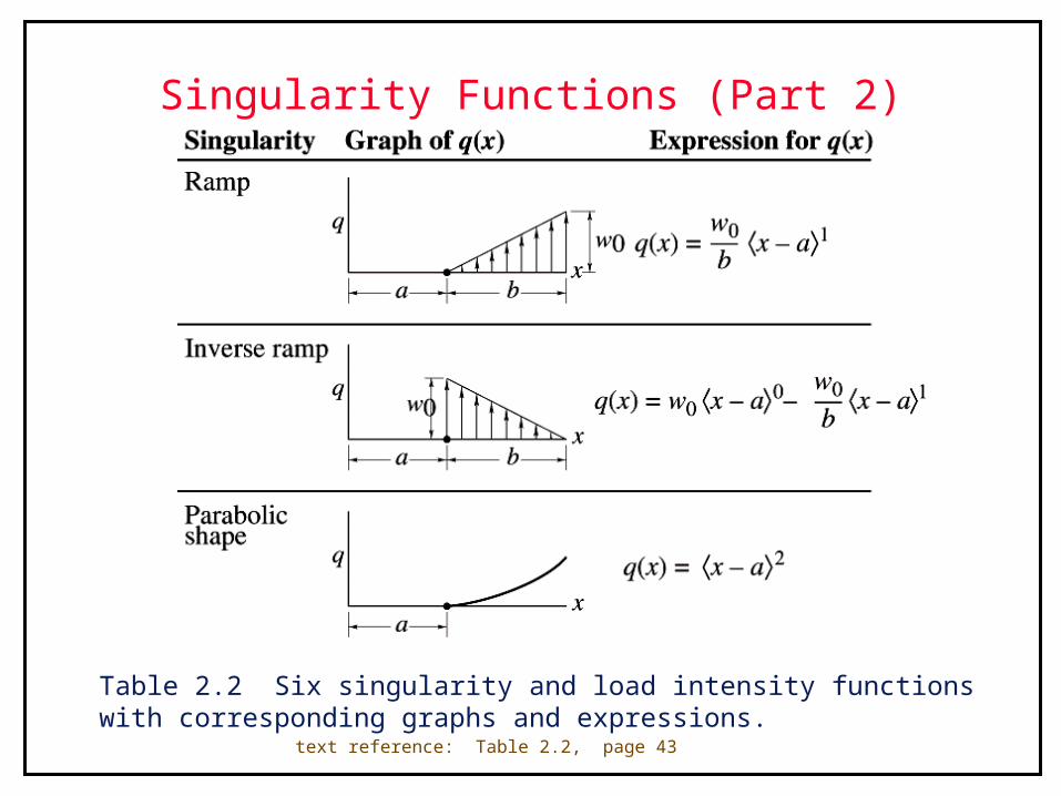
Singularity Functions (Part 2)
Table 2.2 Six singularity and load intensity functions with corresponding graphs and expressions.
text reference: Table 2.2, page 43

Shear and Moment Diagrams
Figure 2.10 (a) Shear and (b) moment diagrams for Example 2.8.
text reference: Figure 2.10, page 44
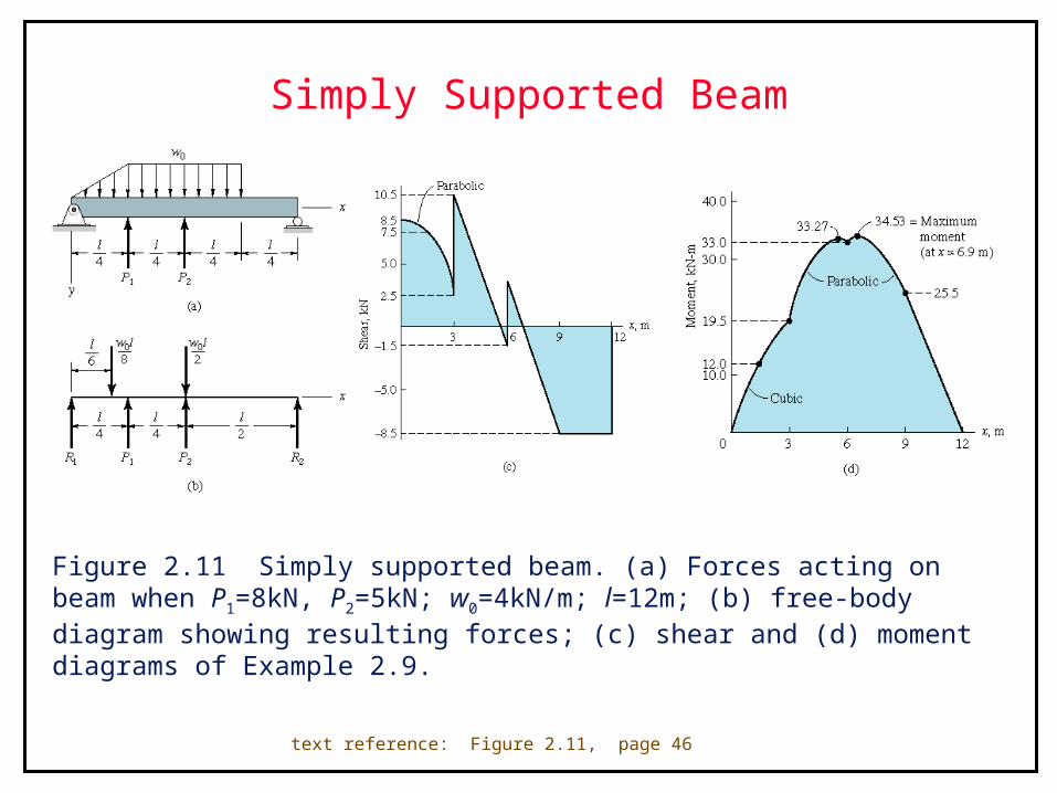
Simply Supported Beam
Figure 2.11 Simply supported beam. (a) Forces acting on beam when P1=8kN, P2=5kN; w0=4kN/m; l=12m; (b) free-body diagram showing resulting forces; (c) shear and (d) moment diagrams of Example 2.9.
text reference: Figure 2.11, page 46
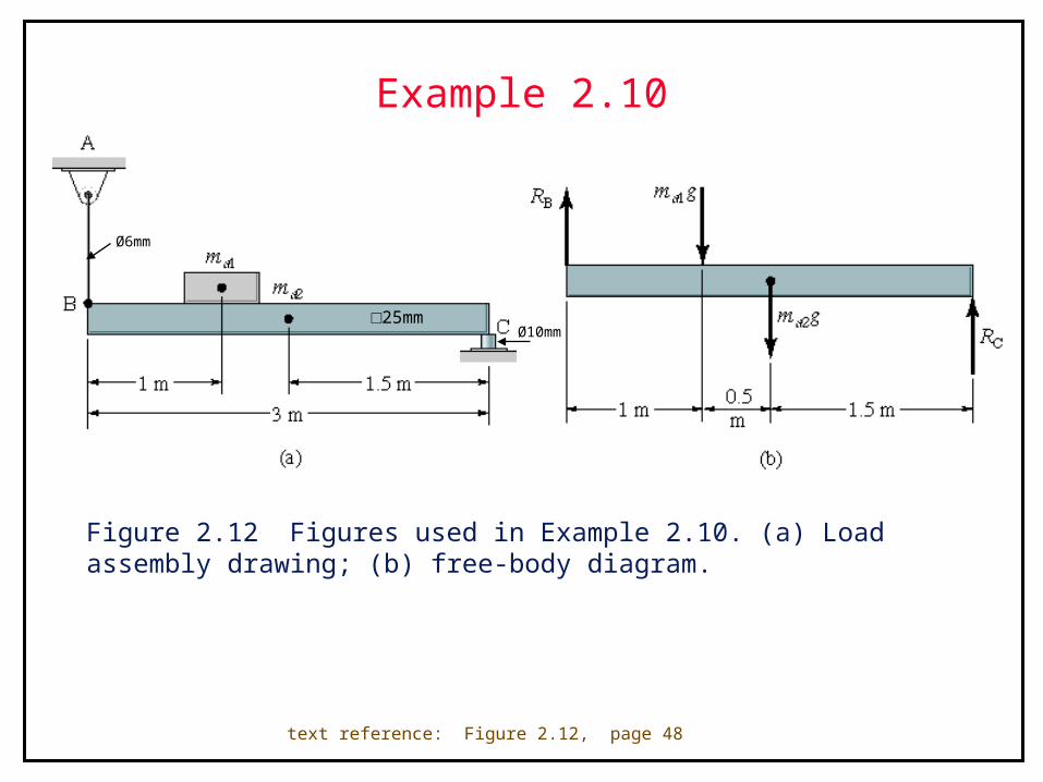
Example 2.10
Figure 2.12 Figures used in Example 2.10. (a) Load assembly drawing; (b) free-body diagram.
text reference: Figure 2.12, page 48
Ø10mm
Ø6mm
□25mm
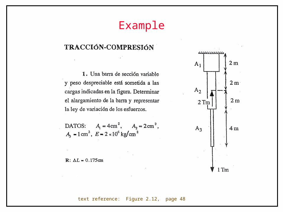
Example
text reference: Figure 2.12, page 48
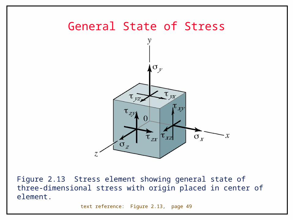
General State of Stress
Figure 2.13 Stress element showing general state of three-dimensional stress with origin placed in center of element.
text reference: Figure 2.13, page 49
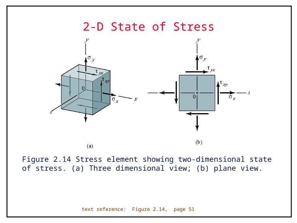
2-D State of Stress
Figure 2.14 Stress element showing two-dimensional state of stress. (a) Three dimensional view; (b) plane view.
text reference: Figure 2.14, page 51
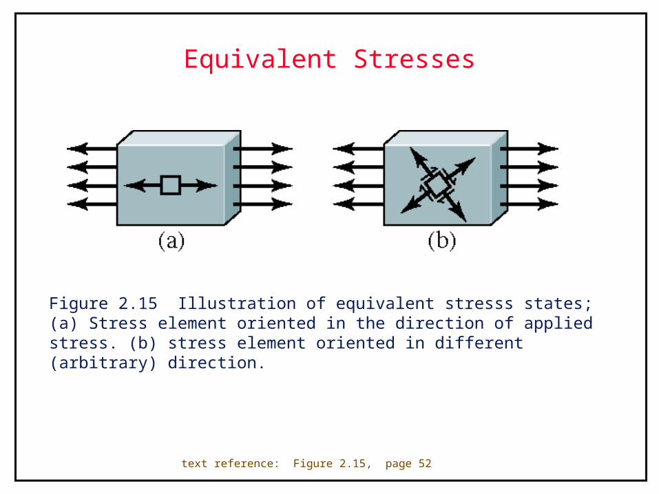
Equivalent Stresses
Figure 2.15 Illustration of equivalent stresss states; (a) Stress element oriented in the direction of applied stress. (b) stress element oriented in different (arbitrary) direction.
text reference: Figure 2.15, page 52
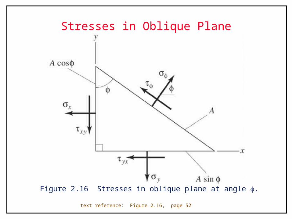
Stresses in Oblique Plane
Figure 2.16 Stresses in oblique plane at angle .
text reference: Figure 2.16, page 52
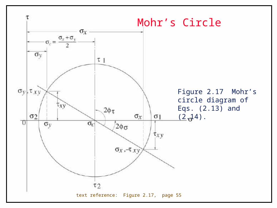
Mohr’s Circle
Figure 2.17 Mohr’s circle diagram of Eqs. (2.13) and (2.14).
text reference: Figure 2.17, page 55
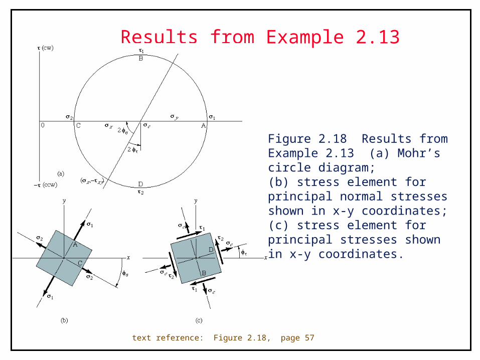
Results from Example 2.13
Figure 2.18 Results from Example 2.13 (a) Mohr’s circle diagram; (b) stress element for principal normal stresses shown in x-y coordinates; (c) stress element for principal stresses shown in x-y coordinates.
text reference: Figure 2.18, page 57
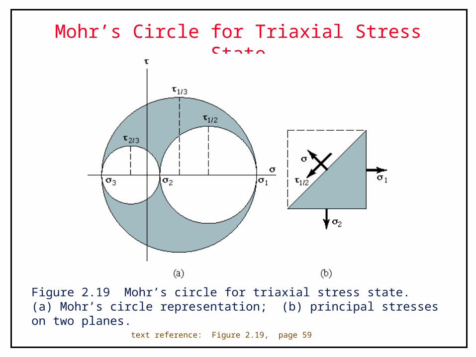
Mohr’s Circle for Triaxial Stress State
Figure 2.19 Mohr’s circle for triaxial stress state. (a) Mohr’s circle representation; (b) principal stresses on two planes.
text reference: Figure 2.19, page 59
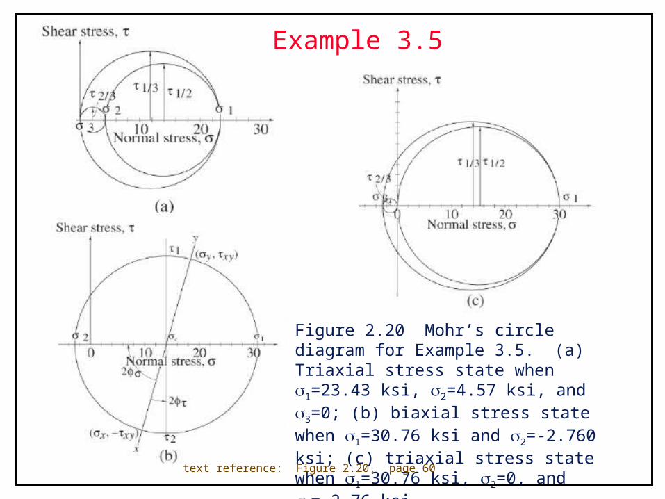
Example 3.5
Figure 2.20 Mohr’s circle diagram for Example 3.5. (a) Triaxial stress state when 1=23.43 ksi, 2=4.57 ksi, and 3=0; (b) biaxial stress state when 1=30.76 ksi and 2=-2.760 ksi; (c) triaxial stress state when 1=30.76 ksi, 2=0, and 3=-2.76 ksi.
text reference: Figure 2.20, page 60
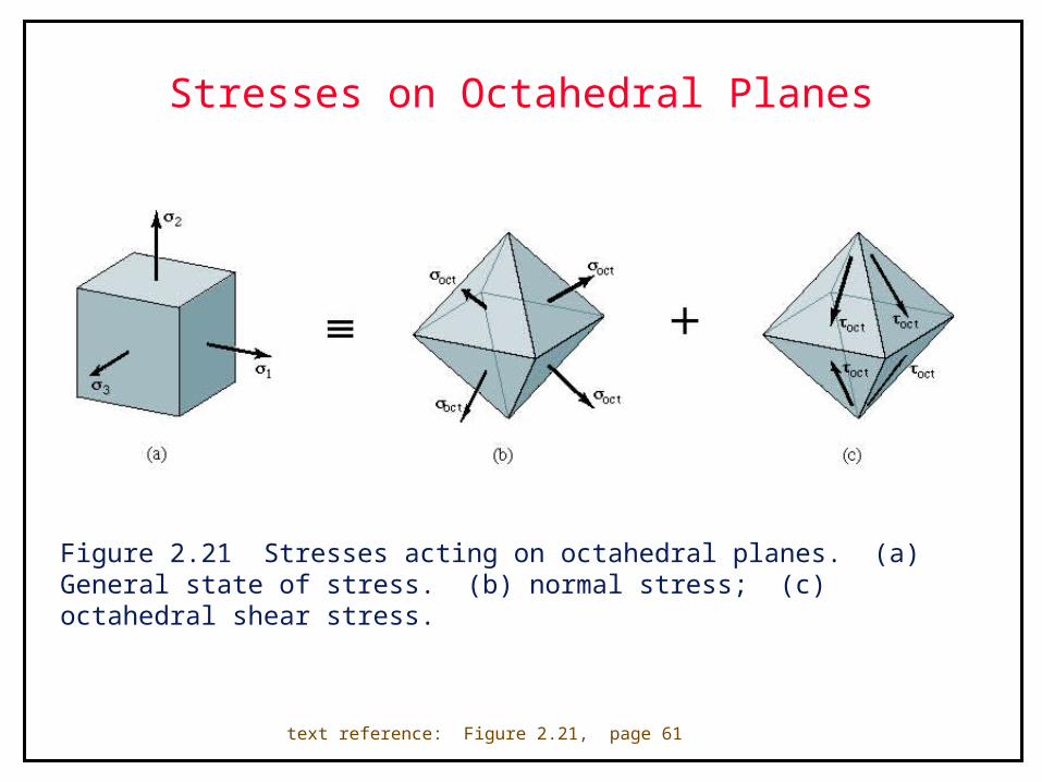
Stresses on Octahedral Planes
Figure 2.21 Stresses acting on octahedral planes. (a) General state of stress. (b) normal stress; (c) octahedral shear stress.
text reference: Figure 2.21, page 61
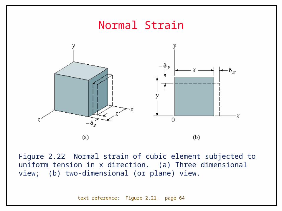
Normal Strain
Figure 2.22 Normal strain of cubic element subjected to uniform tension in x direction. (a) Three dimensional view; (b) two-dimensional (or plane) view.
text reference: Figure 2.21, page 64
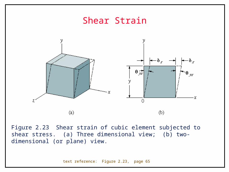
Shear Strain
Figure 2.23 Shear strain of cubic element subjected to shear stress. (a) Three dimensional view; (b) two-dimensional (or plane) view.
text reference: Figure 2.23, page 65

Plain Strain
Figure 2.24 Graphical depiction of plane strain element. (a) Normal strain x; (b) normal strain y; and (c) shear strain xy.
text reference: Figure 2.24, page 66
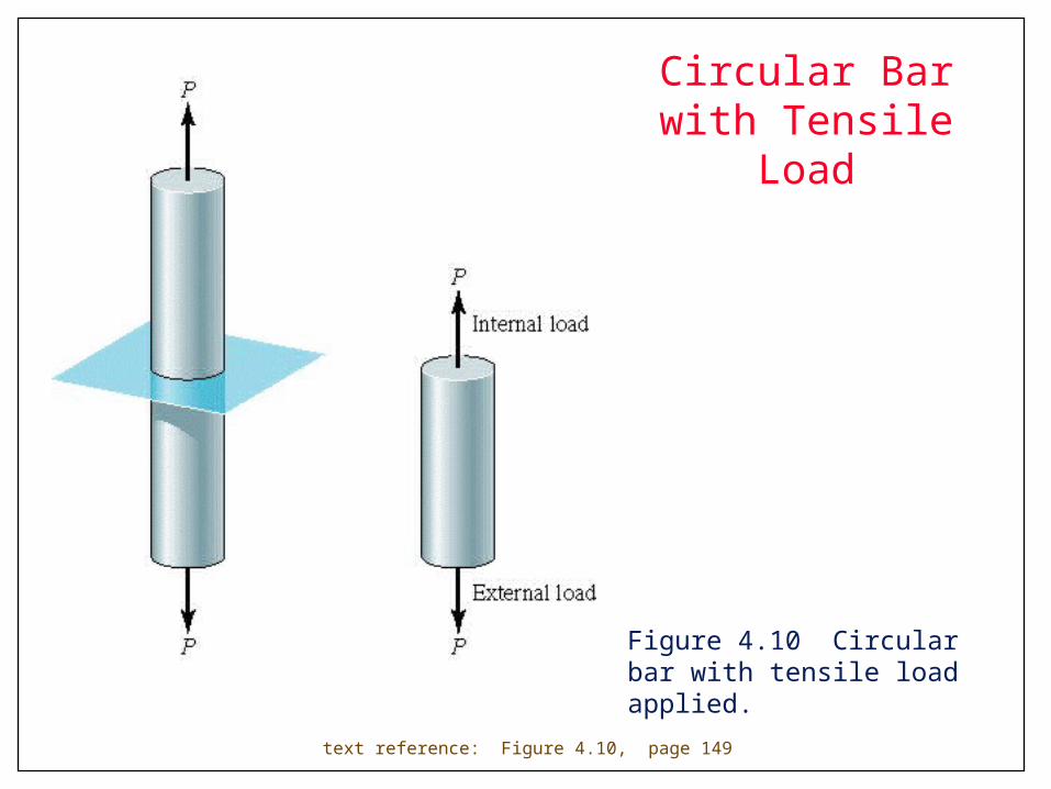
Circular Bar with Tensile Load
Figure 4.10 Circular bar with tensile load applied.
text reference: Figure 4.10, page 149
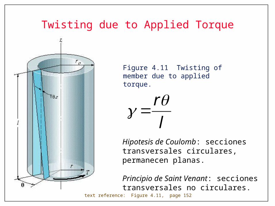
Twisting due to Applied Torque
Figure 4.11 Twisting of member due to applied torque.
text reference: Figure 4.11, page 152
lr
Hipotesis de Coulomb: secciones transversales circulares, permanecen planas.
Principio de Saint Venant: secciones transversales no circulares.
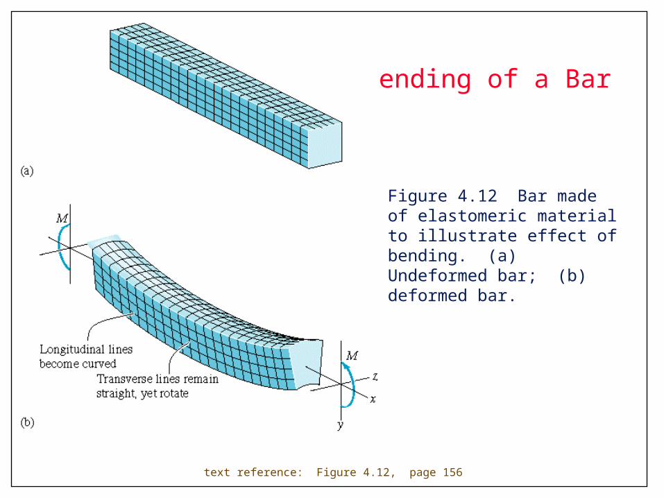
Bending of a Bar
Figure 4.12 Bar made of elastomeric material to illustrate effect of bending. (a) Undeformed bar; (b) deformed bar.
text reference: Figure 4.12, page 156
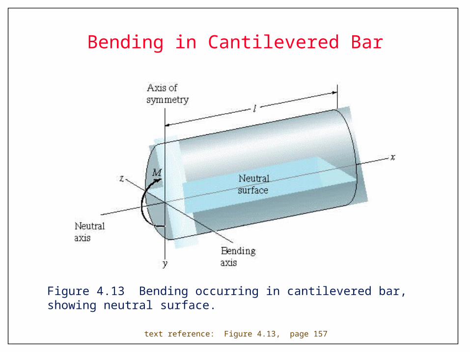
Bending in Cantilevered Bar
Figure 4.13 Bending occurring in cantilevered bar, showing neutral surface.
text reference: Figure 4.13, page 157
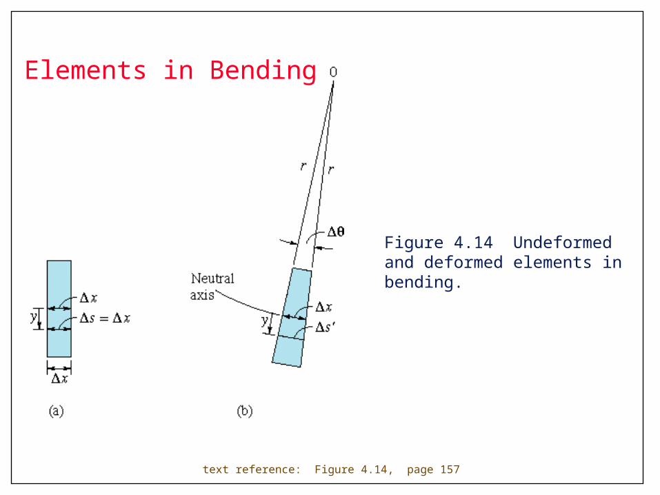
Figure 4.14 Undeformed and deformed elements in bending.
text reference: Figure 4.14, page 157
Elements in Bending
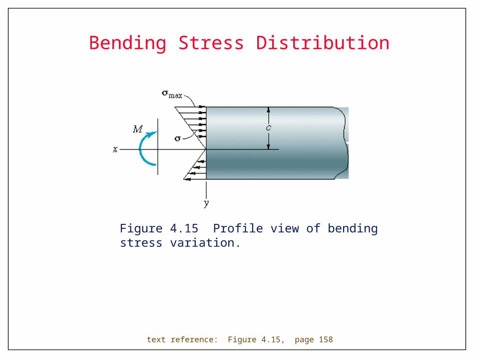
Bending Stress Distribution
Figure 4.15 Profile view of bending stress variation.
text reference: Figure 4.15, page 158
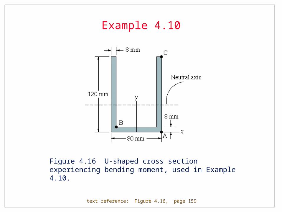
Example 4.10
Figure 4.16 U-shaped cross section experiencing bending moment, used in Example 4.10.
text reference: Figure 4.16, page 159

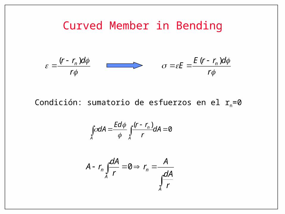
Curved Member in Bending
text reference: Figure 4.17, page 161
rdrr n )(
Curved Member in Bending
0)(
dA
rrrEddA
A
n
A
rdrrEE n )(
r
drr n )(
Condición: sumatorio de esfuerzos en el rn=0
A
nA
n
rdAAr
rdArA 0
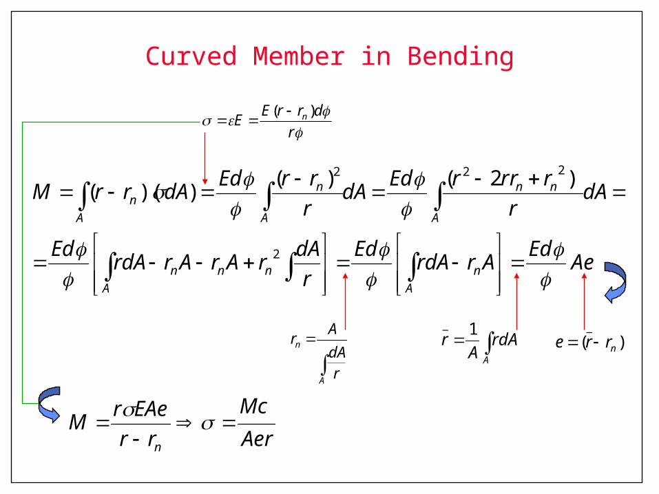
Curved Member in Bending
dArA
rA
1_
rdrrEE n )(
)(_
nrre
A
n
rdAAr
AerMc
rrEAerM
n
AeEdArrdAEdr
dArArArrdAEd
dAr
rrrrEddArrrEddArrM
An
Annn
A
nn
A
n
An
2
222 )2()())((
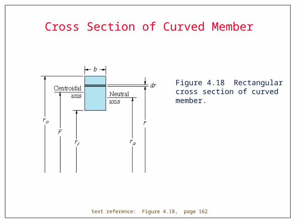
Cross Section of Curved Member
Figure 4.18 Rectangular cross section of curved member.
text reference: Figure 4.18, page 162
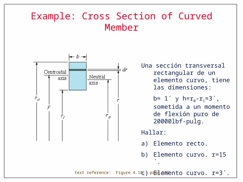
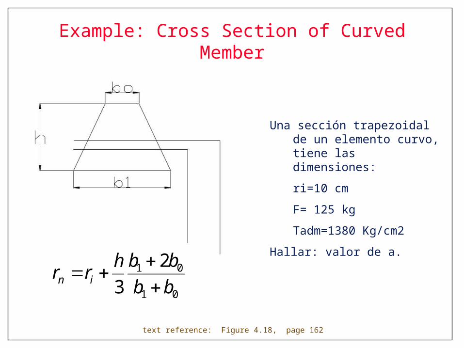
Example: Cross Section of Curved Member
Una sección transversal rectangular de un elemento curvo, tiene las dimensiones:
b= 1´ y h=r0-ri=3´, sometida a un momento de flexión puro de 20000lbf-pulg.
Hallar:
a) Elemento recto.
b) Elemento curvo. r=15´.
c) Elemento curvo. r=3´.
text reference: Figure 4.18, page 162
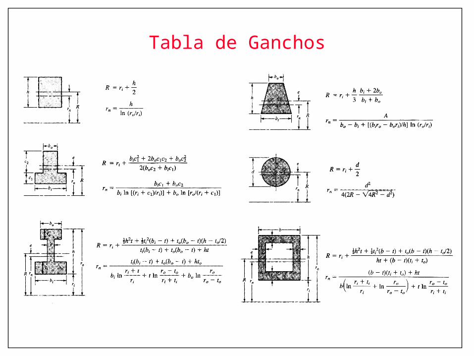
Tabla de Ganchos
Example: Cross Section of Curved Member
Una sección trapezoidal de un elemento curvo, tiene las dimensiones:
ri=10 cm
F= 125 kg
Tadm=1380 Kg/cm2
Hallar: valor de a.
text reference: Figure 4.18, page 162
01
01 23 bb
bbhrr in
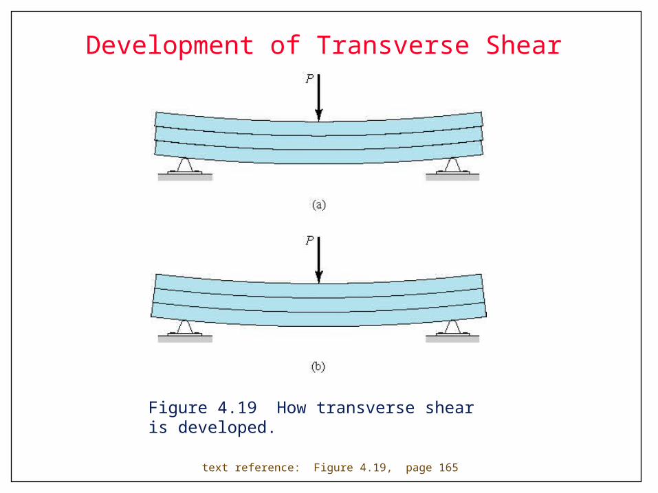
Development of Transverse Shear
Figure 4.19 How transverse shear is developed.
text reference: Figure 4.19, page 165
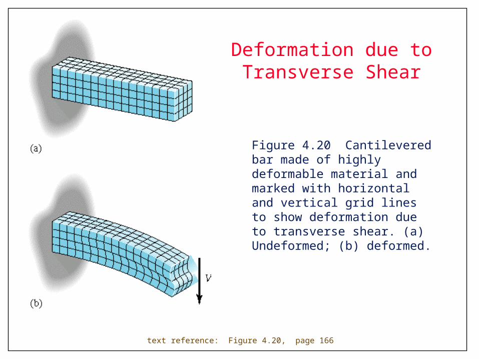
Deformation due to Transverse Shear
Figure 4.20 Cantilevered bar made of highly deformable material and marked with horizontal and vertical grid lines to show deformation due to transverse shear. (a) Undeformed; (b) deformed.
text reference: Figure 4.20, page 166

Moments and Stresses on Elements
Figure 4.21 Three-dimensional and profile views of moments and stresses associated with shaded top segment of element that has been sectioned at y’ about neutral axis. (a) Three-dimensional view; (b) profile view.
text reference: Figure 4.21, page 166
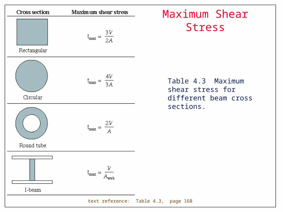
Maximum Shear Stress
Table 4.3 Maximum shear stress for different beam cross sections.
text reference: Table 4.3, page 168
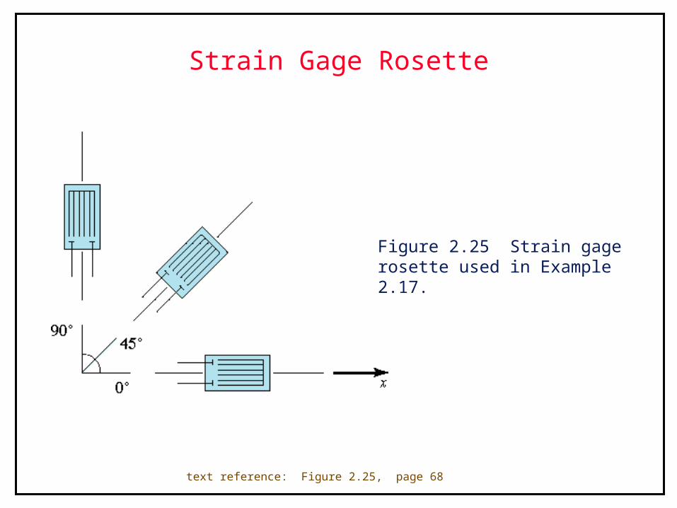
Strain Gage Rosette
Figure 2.25 Strain gage rosette used in Example 2.17.
text reference: Figure 2.25, page 68