
Best Practice in Design and Testing of Isolation Rooms in Nordic Hospitals
57
Nordic Innovation Centre ISSN 0283-7234 Stensberggata 25, 0170 OSLO Telephone +47 47 61 44 00 Fax +47 22 56 55 65 [email protected] www.nordicinnovation.net BEST PRACTICE IN DESIGN AND TESTING OF ISOLATION ROOMS IN NORDIC HOSPITALS James P. Rydock Pål Kjetil Eian Conny Lindqvist Irma Welling Egil Lingaas September 2004 TR 564 Approved 2005-11
-
Upload
manoj-mahendia -
Category
Documents
-
view
156 -
download
1
Transcript of Best Practice in Design and Testing of Isolation Rooms in Nordic Hospitals

Nordic Innovation Centre ISSN 0283-7234 Stensberggata 25, 0170 OSLO Telephone +47 47 61 44 00 Fax +47 22 56 55 65 [email protected] www.nordicinnovation.net
BEST PRACTICE IN DESIGN AND TESTING OF ISOLATION ROOMS
IN NORDIC HOSPITALS
James P. Rydock Pål Kjetil Eian
Conny Lindqvist Irma Welling Egil Lingaas
September 2004
TR 564 Approved 2005-11


NT TECHN REPORT 564 Approved 2005-11
Nordic Innovation Centre project number: 04015 (1646-03)
Authors: James P. Rydock1) Pål Kjetil Eian2) Conny Lindqvist3) Irma Welling4) Egil Lingaas5)
Institution: 1)NBI 2)Norconsult AS 3)Energo AB 4)Finnish Institute of Occupational Health 5)Rikshospitalet
Title:
Best practice in design and testing of isolation rooms in Nordic hospitals Abstract:
At present, there are no international standards available for design and testing of isolation rooms in health-care facilities. Standardization regarding airborne infection (negative pressure) isolation rooms is an important task not only for improving public health across national boundaries, but also for controlling health care costs, as isolation room suites often require con-siderable resources to construct and maintain. An important step in moving toward international standardization is to come to a consensus about what exactly is proper and adequate function in a negative-pressure isolation room. In this report we examine current and best practice in design and performance testing of negative pressure isolation rooms in Nordic hospitals. Design con-siderations and performance monitoring tests for isolation rooms are discussed. Nordic, Euro-pean and other national existing guidelines and standards are examined. Current practice in de-sign and testing of isolation rooms in Nordic hospitals is described, based on information ob-tained from building engineering and health care professionals in over 20 hospitals in Norway, Sweden, Denmark and Finland. Finally, best practice is identified based in part on the review of current and pertinent guidelines, standards, and regulations; in part based on an evaluation of the scientific evidence behind these guidelines, standards and regulations; and in part based on our review of current practice in Nordic hospitals.
Technical Group: Building
ISSN: 0283-7234
Language: English
Pages: 40 p. + appendices
Key Words: Isolation rooms, health-care facilities, negative pressure, airborne infection, standardisation
Distributed by: Nordic Innovation Centre Stensberggata 25 N-0170 Oslo Norway
Report Internet address: www.nordicinnovation.net

i
Foreword This report was authored by Dr. James P. Rydock (Ph.D.) of the Norwegian Building Research Institute with input from a reference group consisting of Mr. Pål Kjetil Eian of Norconsult AS (Norway), Mr. Conny Lindqvist of Energo AB (Sweden), Dr. Irma Welling (Ph.D.) of the Finnish Institute of Occupational Health and Dr. Egil Lingaas (M.D.) of the Norwegian Rikshospital. Valuable input was also received from many building engineering professionals working in the Nordic countries and other countries mentioned in the report. The report was funded in part by Nordtest, an institution under the Nordic Council of Ministers that acts as a joint Nordic body in the field of conformity assessment. Significant funding for completion of the work was also provided by the project group members’ employers, listed above.

ii
Summary At present, there are no international standards available for design and testing of isolation rooms in health-care facilities. Standardization regarding airborne infection (negative pres-sure) isolation rooms is an important task not only for improving public health across national boundaries, but also for controlling health care costs, as isolation room suites often require considerable resources to construct and maintain. An important step in moving toward inter-national standardization is to come to a consensus about what exactly is proper and adequate function in a negative-pressure isolation room. In this report we examine current and best practice in design and performance testing of negative pressure isolation rooms in Nordic hospitals. Design considerations and performance monitoring tests for isolation rooms are discussed. Nordic, European and other national existing guidelines and standards are exam-ined. Current practice in design and testing of isolation rooms in Nordic hospitals is de-scribed, based on information obtained from building engineering and health care profession-als in over 20 hospitals in Norway, Sweden, Denmark and Finland. Finally, best practice is identified based in part on the review of current and pertinent guidelines, standards, and regu-lations; in part based on an evaluation of the scientific evidence behind these guidelines, stan-dards and regulations; and in part based on our review of current practice in Nordic hospitals.
iii
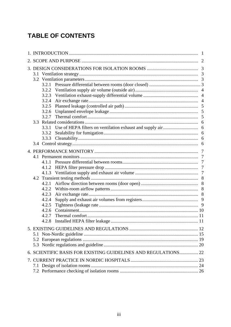
TABLE OF CONTENTS
1. INTRODUCTION............................................................................................................... 1
2. SCOPE AND PURPOSE .................................................................................................... 2
3. DESIGN CONSIDERATIONS FOR ISOLATION ROOMS ............................................ 3 3.1 Ventilation strategy...................................................................................................... 3 3.2 Ventilation parameters ................................................................................................. 3
3.2.1 Pressure differential between rooms (door closed) ............................................ 3 3.2.2 Ventilation supply air volume (outside air) ...................................................... 4 3.2.3 Ventilation exhaust-supply differential volume ............................................... 4 3.2.4 Air exchange rate.............................................................................................. 4 3.2.5 Planned leakage (controlled air path) ............................................................... 5 3.2.6 Unplanned envelope leakage ............................................................................ 5 3.2.7 Thermal comfort ............................................................................................... 5
3.3 Related considerations ................................................................................................. 6 3.3.1 Use of HEPA filters on ventilation exhaust and supply air .............................. 6 3.3.2 Sealability for fumigation................................................................................. 6 3.3.3 Cleanability....................................................................................................... 6
3.4 Control strategy............................................................................................................ 6
4. PERFORMANCE MONITORY ......................................................................................... 7 4.1 Permanent monitors ..................................................................................................... 7
4.1.1 Pressure differential between rooms................................................................. 7 4.1.2 HEPA filter pressure drop ................................................................................ 7 4.1.3 Ventilation supply and exhaust air volume ...................................................... 7
4.2 Transient testing methods ............................................................................................ 8 4.2.1 Airflow direction between rooms (door open) ................................................. 8 4.2.2 Within-room airflow patterns ........................................................................... 8 4.2.3 Air exchange rate.............................................................................................. 8 4.2.4 Supply and exhaust air volumes from registers................................................ 9 4.2.5 Tightness (leakage rate ..................................................................................... 9 4.2.6 Containment...................................................................................................... 10 4.2.7 Thermal comfort ............................................................................................... 11 4.2.8 Installed HEPA filter leakage ........................................................................... 11
5. EXISTING GUIDELINES AND REGULATIONS ........................................................... 12 5.1 Non-Nordic guideline .................................................................................................. 15 5.2 European regulations ................................................................................................... 19 5.3 Nordic regulations and guideline ................................................................................. 20
6. SCIENTIFIC BASIS FOR EXISTING GUIDELINES AND REGULATIONS................ 22
7. CURRENT PRACTICE IN NORDIC HOSPITALS .......................................................... 23 7.1 Design of isolation rooms ............................................................................................ 24 7.2 Performance checking of isolation rooms ................................................................... 26

iv
8. BEST PRACTICE................................................................................................................28 8.1 Design of isolation rooms ............................................................................................ 28 8.2 Performance checking of isolation rooms.................................................................... 32
8.2.1 Permanent monitors .......................................................................................... 32 8.2.2 Commissioning (start-up) ................................................................................. 33 8.2.3 Routine performance monitoring...................................................................... 35
REFERENCES ........................................................................................................................ 38
APPENDIX A. – Additional information from individual Nordic hospitals
APPENDIX B. – Construction details for adequate isolation room tightness

1
1. Introduction At present, there are no international standards available for design and testing of isolation rooms in health-care facilities. Standardization regarding airborne infection (negative pres-sure) isolation rooms is an important task not only for improving public health across national boundaries, but also for controlling health care costs, as isolation room suites often require considerable resources to construct and maintain. An important step in moving toward inter-national standardization is to come to a consensus about what exactly is proper and adequate function in a negative-pressure isolation room. In this report we examine current and best practice in design and performance testing of nega-tive pressure isolation rooms in Nordic hospitals. Protective environment (positive pressure) rooms are not considered here.

2
2. Scope and purpose This document does not address special measures for airborne infection control such as use of ultraviolet disinfection lamps, portable HEPA (for High Efficiency Particulate Arrestance) filter systems or negative-ion generators within isolation rooms, or use of respiratory protec-tion by health care workers. Design of isolation rooms in this report refers specifically to the ventilation strategy, ventilation parameters and related considerations that are necessary for adequate infection protection in an airborne infection (or negative pressure) isolation room. Testing refers to test methods used for performance checking of an isolation room for assess-ing whether the functionality provided by the finished product is adequate, both upon com-missioning and over time, with regard to airborne infection containment. The purpose of the report is to provide an overview of what is currently being done in this area in the Nordic countries and abroad; what is the scientific basis for justifying design speci-fications and test methods in use today; and what is best practice in this area.

3
3. Design considerations for isolation rooms All patient rooms in hospitals should provide an acceptable environment for patients to re-cover and a good working environment for health care professionals who attend to them. The special purpose of an isolation room is to protect health care workers, other patients and visi-tors in a hospital from exposure to an airborne infectious agent in the event that an infectious patient is staying in the room. A principal design goal for an isolation room, then, should be to achieve and maintain an adequate level of airborne infection protection in the environment surrounding an infectious patient. In other words, to contain the airborne infectious material in such a way that the threat of exposure to health care personnel within the isolation room and others outside of the room is minimized. Ventilation is a key component of aerosol con-tainment in isolation rooms. In the following we discuss the ventilation strategy, design pa-rameters and other important related factors that need to be considered in the design of isola-tion rooms.
3.1 Ventilation strategy The strategy in designing ventilation for an isolation room suite should be to obtain the best containment possible while maintaining an acceptable thermal comfort for the patient. The contribution of ventilation to containment can in theory be maximized within an isolation room through source removal, a high dilution rate and a directional airflow from health care personnel to the patient. It is also important that there are no stagnant, under ventilated areas in the room where infectious aerosols might be concentrated. An isolation room suite typi-cally consists of a patient room, attached bathroom and anteroom between the patient room and corridor. Containment can in principle be maximized within an isolation suite by maxi-mizing containment within the patient room, maintaining a directional airflow from the ante-room to the patient room at all times, maintaining a high dilution rate in the anteroom, and maintaining a directional flow from the corridor to the anteroom at all times.
3.2 Ventilation parameters Because containment both within the patient room and within the isolation suite is dependent on so many factors, containment itself cannot be completely described by any single design parameter. The following is an overview of design parameters that can be used to characterize and specify isolation room performance in terms of containment and of thermal comfort for the patient.
3.2.1 Pressure differential between rooms (door closed) A properly functioning isolation room should be maintained at a negative pressure with re-spect to its surroundings, in general, and with respect to the anteroom, in particular, when the door between the room and anteroom is closed. Likewise, the anteroom should maintain a negative pressure with respect to the corridor when the anteroom-corridor door is closed. In other words, a negative pressure differential should exist between the patient room and ante-room and anteroom and corridor when the doors are closed. When the anteroom door is open, air should flow from the corridor to the anteroom. When the patient room door is open, air should flow from the anteroom to the patient room. The pressure differential when the doors are closed is often used as a surrogate measure of containment performance in isolation rooms, and is usually expressed in Pascals (Pa).

4
3.2.2 Ventilation supply air volume (outside air) Ventilation supply air to the patient room in this context is filtered, conditioned outside air supplied directly to the patient room and does not include outside air that has first been sup-plied to the corridor or anteroom before being transferred to the patient room. Likewise, venti-lation supply air to the anteroom is filtered outside air supplied directly to the anteroom, and does not include outside air that has first been supplied to the corridor before passing into the anteroom. Some level of outside supply air will be necessary in a patient room that may be permanently occupied and can have a substantial heating load. This is not necessarily the case in an anteroom that does not have as large a heat load as the patient room and is meant to be occupied only for short time intervals while people are traveling into and out of an isolation room.
3.2.3 Ventilation exhaust-supply differential volume In order that a negative pressure can be achieved and maintained in an isolation room with respect to the surroundings, there must be more ventilation air extracted from the room than is supplied to the room. The patient room ventilation differential volume is given by the exhaust air volume from the room minus the supply air volume to the room. The pressure differential between a room and its surroundings that can be achieved by a given ventilation volume dif-ferential is dependent on the tightness of the room. At steady state, when the pressure differ-ential is constant, the total amount of air going into the room has to be the same as the total amount of air going out. The total amount of air going out is in this case given by the exhaust air volume (plus the exhaust air volume from the attached bathroom, if the bathroom is at a lower absolute pressure than the patient room). The total amount of air going in is given by the ventilation supply air volume plus leakage, or infiltration, driven by the pressure differen-tial between the room and its surroundings. If the room is very tightly sealed (when the door is closed), the pressure differential will have to be relatively large to obtain a given air leakage rate. If the room is not well sealed, the pressure differential to obtain the same leakage rate will be much smaller. In an extremely tight room, a small exhaust-supply differential volume can produce a relatively large pressure differential. Conversely, in a very leaky room, a large exhaust-supply differential volume may not be capable of producing the desired pressure dif-ferential. Optimally, the exhaust-supply air differential volume should be large enough that the doors are not difficult to open and that the ventilation system is stable in operation when doors are opened. This in effect requires an intentional, controlled leakage path into the room (see below).
3.2.4 Air exchange rate Air exchange rate is commonly used as a measure of how quickly contaminants released in a well-mixed zone are removed from the zone (Dilution time is also used to describe contami-nant removal rate, see below). In an isolation room, where infiltration from adjoining spaces can represent a substantial total of the airflow into the room, a distinction must be made be-tween the outside air exchange rate and the total air exchange rate, as these rates can be mark-edly different. The total air exchange rate is given by the ventilation exhaust flow from the room (plus exfiltration from the patient room to the bathroom in the case where the bathroom is at lower absolute pressure than the patient room) divided by the room volume. The outside air exchange rate, on the other hand, is given approximately by the ventilation supply airflow divided by the room volume (direct infiltration of outside air is expected to be minimal in a properly sealed isolation room). The air exchange rate is typically expressed as the number of air exchanges per hour (ACH) in a defined volume. It is commonly used as a parameter describing ventilation in a room as a

5
whole, and assumes complete mixing of supply air throughout the entire volume. Dilution time, on other hand, is expressed as the time necessary for a pollutant concentration to drop to a fractional value of the original concentration at a point in a volume. As such the dilution time can vary at different points in a room with a given air exchange rate, depending on the actual local ventilation effectiveness (which again depends on the degree of mixing of ventila-tion air) at these points.
3.2.5 Planned leakage (controlled air path) Planned leakage provides a controlled air path from the corridor to anteroom and from the anteroom to the patient room in an isolation suite. The planned air leakage into a properly sealed isolation suite normally occurs through or around the doors between these spaces. When a door is closed, the planned leakage will typically be designed to occur through the gap under the door and the unsealed sides and top of the door, or through a grille in the door in the case where a door is sealed around all edges. Alternatively, in the case where a door and door edges are completely sealed, a dedicated duct between rooms can be installed to provide a controlled air path when the door is closed.
3.2.6 Unplanned envelope leakage Unplanned envelope leakage refers to airflow into an isolation suite or room that occurs be-cause of insufficient tightness in joints and penetrations through the suite or room envelope. Common unplanned leakage points include electrical and plumbing outlets and wall-ceiling and floor-wall joints. The sum of the planned and unplanned leakage rates into the isolation room while the room is at the design under pressure should equal the exhaust-supply airflow differential. In order to ensure that the ventilation system is not overly sensitive to changes in the unplanned leakage over time, the unplanned leakage rate upon commissioning should be a small fraction of the planned leakage providing the controlled air path. Leakage rate can be conveniently expressed in this application as a fraction of the exhaust-supply airflow differen-tial or as an air change rate per hour (ACH) at a specified under pressure. Unplanned envelope leakage can be measured by first appropriately and sufficiently sealing the planned leakage paths in an isolation room.
3.2.7 Thermal comfort Isolation rooms have relatively high air exchange rates in relation to other patient rooms. This implies high ventilation air supply and exhaust rates as well. Potentially uncomfortable air velocities (draughts) within the patient room can be a result, and special attention must there-fore be given to thermal comfort, particularly for the patient, as a design issue. Draught risk, defined in EN ISO 7730 [1], is dependent not only on local air velocity, but also on air tem-perature, relative humidity and clothing and activity levels of people in the room.

6
3.3 Related considerations There are several other important design considerations for isolation room suites that fall within the scope of this document. These are discussed below.
3.3.1 Use of HEPA filters on ventilation exhaust and supply air Because ventilation ducts leading to and from an isolation room suite can potentially be routes of transfer of airborne infectious aerosols out of an isolation room, use of HEPA filters should be considered in the design of the ventilation system. This includes consideration of how the filters will be safely replaced as well as periodically performance-checked. While use of HEPA filters is not directly related to ventilation and containment performance within an iso-lation room suite and between the suite and the corridor, HEPA filtration in isolation room ductwork can have a substantial impact on the investment and operational cost and complex-ity of the ventilation system.
3.3.2 Sealability for fumigation Because an isolation room may need to be fumigated after an infectious patient has been in the room, the ability to fumigate the room should be considered in the isolation room design. In order to minimize the risk of exposure to other building occupants during and after fumiga-tion, an isolation room should be able to be sealed (to be made gastight).
3.3.3 Cleanability The ability to adequately, effectively and routinely clean and disinfect surfaces in an isolation room suite and the relevant components of the ventilation system serving the room (when necessary) needs to be considered at the design stage.
3.4 Control strategy The ventilation system of an isolation suite should be designed to achieve and maintain (within agreed upon acceptance limits) desired values of the design parameters discussed above. An isolation room suite in service will be subjected to disturbances that can affect the ventilation system, most notably when doors are opened and people enter and leave the suite. However, an isolation room suite is generally, in addition, an integral part of a hospital build-ing containing other complexly ventilated spaces. Both the building and its individual rooms and spaces will be subjected to changing stack and wind pressure effects over time. In order to maintain the desired containment function in an isolation suite in the presence of these distur-bances and changes in the external environment, the ventilation system must be designed with a control strategy in mind. A primary control requirement is an interlocking system between doors that ensures that both the corridor-anteroom and anteroom-patient room doors cannot be opened at the same time. In addition, there are two fundamental control strategies that reflect the basic ventilation strategy discussed above of achieving containment between patient room and anteroom and anteroom room and corridor. One strategy is to maintain constant exhaust-supply flow differentials under changing conditions and accept that the pressure differentials between patient room and anteroom and anteroom and corridor will vary. The second strategy is to maintain constant pressure differentials under changing conditions by varying the ex-haust-supply flow differentials. Alternatively, a combination of the two approaches can be used. Choice of ventilation control strategy can have a profound impact on the cost and com-plexity of isolation room ventilation.

7
4. Performance monitoring Performance monitoring with measuring equipment can consist of a combination of measur-ing with permanent monitors and monitoring using transient testing methods, that is to say bringing equipment in, doing a test or check, and removing the equipment.
4.1 Permanent monitors This refers to permanently installed equipment for monitoring some aspect of isolation room containment performance.
4.1.1 Pressure differential between rooms Presence of a permanent monitor providing information about whether the isolation room is maintaining negative pressure with respect to the surroundings means that that the status of the isolation suite can be rapidly assessed at any time and that problems can be quickly dis-covered and addressed. 4.1.1.1 Direct-reading pressure gauge A direct-reading pressure gauge indicates whether a measurable pressure differential exists between the two rooms. Equipment: See ref. [2]. 4.1.1.2 Airflow direction monitor A pressure differential between two rooms drives air through an opening in the wall between the rooms. A measuring device, such as a ball-in-tube or flutter strip, is installed in the open-ing in order to continuously monitor the airflow direction. This can be used as a substitute for direct reading of pressure differentials. Equipment: See ref. [3].
4.1.2 HEPA filter pressure drop As a HEPA filter collects particulate matter and gets clogged over time, the pressure drop across the filter will increase. When the predetermined HEPA filter pressure drop limit is reached, the filter element must be changed. A clogged HEPA filter on the exhaust side can, for example, result in a dramatically reduced exhaust airflow rate that can compromise isola-tion room suite containment performance. Equipment: See ref. [2].
4.1.3 Ventilation supply and exhaust air volumes In the event that the control strategy for ventilation of an isolation suite involves adjusting ventilation supply and exhaust volumes, the system controller may require measurement of ventilation supply and exhaust volumes as a feedback input. In this case, permanent airflow monitors may need to be installed in the supply and exhaust ducts. Equipment: Venturi meter or orifice meter, see ref. [2].

8
4.2 Transient testing methods This refers to transient tests that can be performed before or upon commissioning or as peri-odic maintenance tests to document isolation room performance over time. This section gives an overview of testing methods for evaluating isolation rooms, based on information obtained from the scientific literature, from national isolation room standard, from international stan-dards for related environments such as cleanrooms and from engineering and health care pro-fessional working in this area. Where two or more methods are given for a test, advantages and disadvantages (if applicable) are listed for each.
4.2.1 Airflow direction between rooms (door open) This is a qualitative test with a smoke release to examine whether air flows inward, both near the floor and near the ceiling in the doorway when the patient room door is open and when the anteroom door is open. Equipment: Smoke tube Procedure: Release smoke and observe movement patterns.
4.2.2 Within-room airflow patterns This is a qualitative test with a smoke release to examine airflow patterns within the patient room. Equipment: Smoke tube Procedure: Release smoke and observe movement patterns. Examine whether short-circuiting occurs between supply and exhaust registers within patient room. Look for stagnant areas where air is not well mixed. Assess whether airflow within room is from the health care worker to the patient and then to the exhaust register (and out of the room).
4.2.3 Air exchange rate The air exchange rate can be obtained in the patient room by dividing the ventilation exhaust rate by the room volume. It can also be measured directly using a tracer release. 4.2.3.1 Tracer methods Require trained personnel and specialized equipment not usually available from most ventila-tion contractors.
4.2.3.1.1 Method 1: Tracer decay rate A tracer is instantaneously released into the room and the concentration decay over time is observed. This method can also be used to measure the dilution rate at a point or points in a room. Equipment & procedure: See refs. [4], [5] & [6] Advantages: Can give a more accurate measurement of air exchange rate than direct meas-urement of supply and exhaust airflow rates. Can be used to assess ventilation effectiveness in different areas of a room if multiple measurement points are used.

9
4.2.3.1.2 Method 2: Tracer constant release method A tracer gas is released at a known rate into the volume. Measurement of the steady state tracer gas concentration yields a quantitative measure of air exchange rate in the volume Equipment & procedure: See ref. [4] Advantages: Can give a more accurate measurement of air exchange rate than direct meas-urement of supply and exhaust airflow rates. Can be used to assess ventilation effectiveness in different areas of a room if multiple measurement points are used. Disadvantages: Requires use of more tracer gas than tracer decay method. This can be an is-sue where environmentally sensitive tracer gases are used. Requires knowledge of room vol-ume to calculate air change rate.
4.2.4 Supply and exhaust air volumes from registers There are a number of ways of measuring supply and exhaust air volumes from ventilation registers in isolation room suites. Measurement of these rates can also in some situation be used as a substitute for the measurement of air exchange rate directly with a tracer gas (See 4.2.3.1 above). Equipment & procedure: See ref. [2].
4.2.5 Tightness (leakage rate) There are a number of ways of measuring the leakage rate, both quantitatively and qualita-tively. 4.2.5.1 Smoke visualization combined with pressurization This method can be used to check for leakage visually by releasing smoke at suspected leak-age locations while the isolation room is at under or over pressure with respect to the sur-roundings Equipment: Smoke tube, pressure gauge Procedure: Pressurize room by closing and sealing appropriate ventilation registers and other envelope openings (such as doors) and shutting off supply or exhaust fan. Measure under or over pressure with pressure gauge and look for leaks with smoke source. Advantages: Smoke tubes are inexpensive and relatively easy to obtain. Disadvantages: Some types of smoke are acrid, can be difficult to see smoke in low light con-ditions or in cases where room walls are white. This is a qualitative measure of envelope leak-age.

10
4.2.5.2 Fan pressurization method This method quantifies leakage rate in m3/hr by measures airflow rate into or out of the room at a specified pressure differential, commonly done with commercially available ‘blower door’ apparatus. Equipment & procedure: See ref. [7]. Use of blower door apparatus in most cases means that the planned leakage path through the door is sealed during the test. Alternately, a sufficient pressure differential can possibly be obtained in an isolation room by turning off the supply fan and sealing (using tape and plastic sheeting, for example) supply registers and planned leakage paths. Measurement of the airflow rate through the exhaust register can then yield a leakage rate directly. Both of these methods yield an upper limit to the unplanned leakage, limited by the extent to which planned leakage paths or unfinished openings (in the case where the test is performed before the isolation room is complete) can be blocked during the test. Advantages: This is a quantitative measure of leakage. Disadvantages: Blower-door test requires specialized equipment. Testing can be relatively time consuming and obtrusive, requiring transport and set up of bulky equipment. Most com-mercially available blower doors are not supplied with flow measuring devices that can quan-tify the design leakage rate from a properly sealed isolation room (less than 100 m3/hr at a pressure differential of 50 Pa). Therefore, if blower door is to be meaningfully used, a non-standard flow-measuring device must be employed. Measurement of exhaust flow requires appropriate measurement access to exhaust register.
4.2.5.3 Tracer method: measure air exchange rate during pressurization This method quantifies leakage rate in ACH by measuring the tracer concentration decay rate while the room is pressurized Equipment: Tracer test equipment for measuring air exchange rate (See 4.2.3.1 above), pres-sure gauge. Procedure: Pressurize room by closing and sealing supply vents and other envelope openings (such as doors) and shutting off supply fan. Adjust exhaust air so that a pressure of –50 Pa is achieved in the room. Measure air exchange rate using a tracer method as described in 4.2.3.1. Advantages: This is a quantitative measure of envelope leakage that is more sensitive than a leakage determination done with a flow-measuring device supplied with a commercially available blower door apparatus (See 4.2.5.2 above). Using this method, a leakage rate down to less than 10 m3/hr at a pressure differential of 50 Pa can typically be measured. Disadvantages: Requires trained personnel and specialized equipment not usually available from most ventilation contractors.
4.2.6 Containment Containment with regard to an isolation room suite refers to the ability of the suite to withhold airborne infectious substances, particularly when persons exit the room and suite. Contain-ment is not in itself a currently established design parameter
11
4.2.6.1 Point release tracer method Containment of an instantaneously released point tracer source at the patient bed is measured from the patient room to the anteroom and anteroom to corridor in an isolation room suite. Equipment: Disposable polyethylene syringes with caps for tracer release and sampling, a gas chromatograph to analyze sulfur hexafluoride tracer in air at levels down to low parts-per-trillion-volume. (Note: Release of sulfur hexafluoride is banned in Denmark because of its strong global warming potential). Procedure: Tracer is instantaneously released at the position of the patient bed in the patient room. Tracer concentrations are measured in the anteroom and corridor outside of the patient room after a person exits the room and anteroom. Advantages: Doesn’t require any set up time beforehand. Provides a true measurement of con-tainment of gaseous aerosols. Disadvantages: Requires trained personnel and specialized equipment not usually available from most ventilation consultants or contractors. References: [8], [9] 4.2.6.2 Constant tracer release method Equipment & procedure: Similar to 4.2.6.1 above, except a constant release of tracer gas is used in patient room, resulting in a steady-state constant concentration of tracer gas in the volume Advantages: Provides a true measure of containment of a gaseous aerosol when persons exit an isolation room or suite. Disadvantages: Requires trained personnel and expensive equipment not usually available from most ventilation consultants or contractors. Relatively obtrusive procedure (in compari-son to point release tracer method), requiring transport and set up of equipment before test and break down and removal of equipment after test.
4.2.7 Thermal comfort Equipment & procedure: Measure draught rating in accordance with ISO 7726 [10] and ISO 7730 [1] at the position of the head of the patient.
4.2.8 Installed HEPA filter leakage Refers to the leakage of aerosol through or around an installed HEPA filter when an aerosol challenge is presented upstream of the filter. Equipment & procedure: See ref. [2].
12
5. Existing guidelines and regulations In this section we focus on guidelines specifically pertaining to isolation rooms. In addition, we also look at several relevant regulations applicable in the Nordic countries for work envi-ronments in which biological hazards may be encountered, particularly two European Union Directives and an adaptation and translation of these directives into a work environment regu-lation in Norway. A summary of recommended values of design parameters from selected isolation room guidelines is given in Table 1 below. The list of guidelines and countries is not meant to be all-inclusive globally. The work environment regulations mentioned above are not included in Table 1 as they do not make specific recommendations about design values for isolation rooms. Rather, they list more general requirements that can have implications for isolation room design and approval for use in treating infectious patients. Strictly speaking, the guidelines we have examined do not as a rule make a distinction be-tween ‘design’ values and ‘commissioning’ or ‘in-use’ values for these parameters. We use ‘design’ parameters here in order to be consistent with the background information provided in section 3.2. Only design parameters that appear in at least one of the guidelines and for at least one of the areas we are focussing on (patient room and anteroom of an isolation suite and corridor outside of the suite) are listed in Table 1. For example, because no design values for leakage rates (either intentional, unintentional or total) appear in any of the guidelines dis-cussed below, this parameter is not included in the table. Recommended permanent monitoring and commissioning and maintenance tests for isolation rooms in each of the countries with guidelines discussed in this report are given in Table 2. Appearance of a test (as defined in section 4 above) in Table 2 signifies that the test is specifi-cally mentioned in the referenced guideline from that country. The individual guidelines from which the data in Table 1 and Table 2 are obtained are discussed in the following sections.

13
Table 1 – Current recommended minimum values of design parameters for isolation rooms from guidelines in different countries. Values listed for USA for each parameter are the high-est among the three referenced guidelines (CDC, AIA & ASHRAE).
Patient room Anteroom Corridor Country Pressure
Differential2 Exhaust-supply
Airflow differential
Air exch. rate
Pressure Differential3
Air exch. rate
Air exch. rate
USA 2.5* 126 m3/h† 2 & 12¤§ (+,-)6 2 & 10†§ 2 & 4†§ UK --4 10% or 85 m3/h† 6-12†
Canada --4 10% or 85 m3/h† 9† Australia1 30 15† 15
Japan --8 2 & 6-12§ --7 Norway 15 10-12† 5 10# Sweden -- --5
Denmark 15 12† 5 -- Signifies that no numerical value for pressure differential is given in the guideline * from CDC [12], AIA [13] & ASHRAE [14] † From ASHRAE [14] ¤ from AIA [13] & ASHRAE [14] § First number represents minimum outside air exchange rate, second number represents
minimum total air exchange rate) # A distinction is not made between outside air exchange rate and total air exchange rate
(outside air plus infiltration/exfiltration) 1 Several states/territories have developed their own guidelines in Australia. Here we have
referenced standards from Victoria [15] and Queensland [16]. 2 Denotes patient room-corridor pressure differential 3 Denotes anteroom-corridor pressure differential 4 Patient room should have enough negative pressure to maintain airflow from corridor into
room. The negative pressure must be measurable. 5 Anteroom should be negative with respect to both patient room and corridor so that rooms
can be used for both positive and negative isolation 6 Anteroom can be either positive or negative with respect to corridor 7 Should be negative with respect to corridor 8 Should be negative with respect to anteroom.

14
Table 2 - Current recommended isolation room permanent monitors and commissioning and routine performance checks in guidelines from selected countries. Key for numerical codes is given below.
Country Permanent monitors Commissioning checks Routine performance checks
USA1 1, 2 1 or 3, 4¤, 10 1 or 3, 10† UK 1 * 1, 3
Canada2 3, 6 * 3 Australia3 1 -- 5,6
Japan -- -- -- Norway4 1 4, 5, 8§, 9 7‡, 10 Sweden -- -- --
Denmark4 1 4, 5, 8§, 9 7‡, 10
1 From CDC [11] 2 Airflow direction can be verified using permanent monitors or periodic testing 3 From Victoria [15] guidelines. The maintenance tests should occur at an interval not
greater than 13 weeks. 4 Tests in Norwegian [17] and Danish guidelines [18] are not specifically called ‘commis-
sioning’ or ‘maintenance’ tests. Classification of the tests is therefore our own interpreta-tion, based on the wording of the text in the document. For the maintenance tests, the guidelines specify tests that ‘can be included’ and not ‘shall be included’.
¤ Standard describes how test can be done without actually recommending that it should be done or specifying when.
† To be repeated every six months * There is no specific distinction between commissioning and maintenance tests in the refer-
enced guideline(s) from this country. § No guidance is given about how to perform a containment test or what value is acceptable. ‡ No acceptable values for tightness are specified. Numerical codes for monitoring and tests in Table 2 (a description of these is given in Section 4 above): 1 : Pressure differential between rooms 2 : HEPA filter pressure drop 3 : Airflow direction between rooms 4 : Within room airflow patterns 5 : Air exchange rate 6 : Supply and exhaust airflow rates from registers 7 : Tightness (leakage rate) 8 : Containment 9 : Thermal comfort 10 : HEPA filter leakage.

15
5.1 Non-Nordic guidelines The guidelines discussed in this section are from the United States, United Kingdom, Canada, Australia and Japan.
5.1.1 United States of America Guidelines for ventilation in isolation rooms are available from several different sources in the United States, including the Centers for Disease Control and Prevention (CDC), American Institute of Architects (AIA) and American Society for Heating and Refrigeration Engineers (ASHRAE). Recommendations from these guidelines are generally broadly consistent with one another, and give details in varying degrees about different design aspects of airborne infection isolation rooms. 5.1.1.1 Centers for Disease Control and Prevention (USA) CDC’s ‘Guidelines for Preventing the Transmission of Mycobacterium Tuberculosis in Health-Care Facilities’ [11] is a standard reference in most literature pertaining to airborne infection protection isolation rooms in hospitals. These guidelines recommend at least 0.001 inch of water (or 0.25 Pa) under pressure in a negative pressure isolation room in order to achieve and maintain a flow of air into the room. This is clearly meant to be an absolute minimum pressure difference. Further, it is stated that this can normally be achieved by ad-justing the room supply and exhaust flows so that there is an exhaust flow at least 10% or 50 cubic feet per minute (cfm) greater that the supply (whichever is greater). If this amount of excess exhaust flow does not result in at least 0.001 inch of water (0.25 Pa) under pressure then the room should be evaluated for leaks. The CDC’s guidelines for prevention of tuberculosis recommend that air in an isolation room should flow from clean parts of the room where health personnel are likely to work, across the infectious source and into the exhaust. A suggested way of achieving this is with supply air at one side of the room (opposite the patient) and exhaust at the other side (the side with the pa-tient bed). An alternative is described in which air is supplied at the ceiling and exhausted near the floor level. Two figures are provided in the document to illustrate this. The first shows two supply registers on one wall and two exhaust registers on the opposite wall. The second shows two supply registers on the ceiling and one exhaust register each low down on opposing walls. In more recent issuances from the CDC (for example ‘Guidelines for Environmental Infection Control in Health-Care Facilities’, which appeared in June 2003 [12]), the recommended pressure differential is increased to at least 2.5 Pa between patient room and corridor. In a figure in an appendix to this document, an exhaust-supply airflow differential of at least 125 cubic feet per minute (212 m3/hr) and a leakage area of 0.5 square feet (465 cm2) are recom-mended for airborne infection isolation rooms. With regard to monitoring and testing, The CDC guidelines specify that, where HEPA filters are used, they should be adequately leak tested upon commissioning and every six months thereafter in systems where exhaust air is likely to be contaminated with M. tuberculosis (for example isolation rooms). Furthermore, proper flow direction between rooms or a negative pressure differential should be verified regularly (at least once per day when isolation rooms are in use, at least once per month when not in use) using smoke tubes or a manometer, even in systems where permanent pressure monitoring devices are installed and in use. In addition,

16
these guidelines describe how air flow patterns within rooms can be investigated using smoke tubes, without actually saying that this type of test should be done upon commissioning or as a maintenance test. Though recommended air exchange rates and exhaust supply airflow dif-ferentials are provided (see Table 1 above) no mention of how or when these parameters are to be measured or verified is given in the CDC guidelines. 5.1.1.2 The American Institute of Architects The AIA publishes ‘Guidelines for Design and Construction of Hospitals and Health Care Facilities’ [13], with the most recent updated version appearing in 2001. The AIA Guidelines recommend a minimum outdoor air exchange rate of two per hour, with a minimum total air exchange rate of 12 per hour in the patient room. A total air exchange rate of 10 per hour is recommended for the anteroom. The differential pressure between room and corridor should be at least 2.5 Pa. The AIA guidelines do not specify whether an anteroom is needed or how an anteroom of a negative-pressure isolation room should be ventilated. The only specific guidance about loca-tions of air supply and return ducts is that the bottoms of ventilation openings shall be at least three inches (76.2 millimeters) above the floor in all hospital rooms. The AIA guidelines also specify that airborne infection isolation rooms shall have a perma-nently installed visual mechanism for monitoring the pressure status of the room when occu-pied by an infectious patient, and that the mechanism shall continuously monitor the direction of airflow. The AIA guidelines are updated every four to five years. 5.1.1.3 American Society of Heating Refrigerating and Air-Conditioning Engineers ASHRAE recently published new design guidelines for hospitals entitled ‘HVAC Design Manual for Hospitals and Clinics’[14]. The ASHRAE Guidelines recommend a minimum outdoor air exchange rate of two per hour, with a minimum total air exchange rate of 12 per hour in the patient room. A total air exchange rate of 10 per hour is recommended for the an-teroom, with an outdoor air exchange rate of two per hour. The differential pressure between room and corridor should be at least 2.5 Pa, with an exhaust-supply airflow differential of at least 75 cfm (126 m3/hr). A reasonable exhaust-supply airflow differential is listed as 100 cfm (170 m3/hr). The ASHRAE guidelines point out that in practice, the positioning of the exhaust register in the patient room has little effect on the room airflow pattern. Also, in practice, the achieve-ment of a directional flow pattern from caregiver to patient and then out of the room is not realistic at the modest air exchange rates found in isolation rooms. Thus, the best practice ven-tilation strategy is to achieve effective mixing and the highest contaminant dilution rate that is consistent with maintenance of an acceptable thermal comfort in an isolation room suite. This can be achieved with ceiling mounted, horizontal-throw diffusers located near the center of the room or slightly toward the entrance, and ceiling mounted exhaust registers located over the patient bed.

17
5.1.2 United Kingdom The Prevention and Control of Tuberculosis in the United Kingdom [19] is available on the internet at http://www.open.gov.uk/doh.coinh.htm. This document also uses the US CDC Guidelines as a basis. 6-12 air changes per hour are recommended for isolation rooms. The document points out that the minimum pressure difference of 0.25 Pa in the CDC Guidelines (from 1994) is a value not readily measurable, and therefore that a larger pressure differential is advised. A minimum pressure differential is, however, not defined in this document. It is the direction of flow that is important, not an absolute pressure differential. The document advises that a range of acceptable pressures be defined upon commissioning of an isolation room, and that some type of gauge or readout that can indicate pressure differential be in-stalled and checked daily, with results documented. Smoke testing can in some cases provide periodic visualization of air patterns at the door of an isolation room, but this alone is not an adequate method for periodic performance checking. With regard to exhaust-supply airflow differential, this document references the CDC recom-mendation of 10% of supply air or 50 cfm (85 m3/hr), whichever is greater, but points out that this is a minimum and that there is little practical reason to not employ a much greater differ-ential. HEPA filtration on exhaust air is ‘rarely required’, and can adversely reduce the rate of air-flow. Coarse filtration is less likely to adversely affect the exhaust flow rate. A high airflow rate is the important feature for exhaust air. No guidance about placement and number of supply and exhaust registers in isolation room suite.
5.1.3 Canada Guidelines for Preventing the Transmission of Tuberculosis in Canadian Health Care Facili-ties and Other Institutional Settings [20]. This document recommends that new isolation rooms have nine air changes per hour (ACH) and negative pressure with respect to the corri-dor, resulting in inward flowing air. The 10%/50 cfm greater exhaust rule of thumb used in the CDC guidelines is also recommended here, with no number given for a minimum accept-able negative pressure differential in an isolation room. The location of supply and exhaust registers should achieve an airflow from the doorway to the patient, and should be positioned in a manner such that all parts of the room are adequately ventilated, but no more specific guidance about placement is given. The inward direction of flow must be verified regularly, either with a permanently mounted electronic monitor which gives information about the ‘efficacy of the inward directional flow system and rate of air change’ or with smoke tests. A reasonable smoke test frequency is sug-gested to be once every six months for isolation rooms not in use and once weekly for rooms occupied by infectious patients.
5.1.4 Australia In Australia, guidelines for airborne infection protection rooms in hospitals have been devel-oped at the state and territory level. There are also guidelines at the national level. Here we present guidelines from Victoria [15] and Queensland [16]. These are nearly identical and are both very detailed documents that incorporate many of the elements of the CDC guidelines

18
discussed in 5.1.1.1, except pressure differentials are increased to 30 Pa between room and adjacent ambient pressure areas (for example, corridor) if a suite has an anteroom, and at least 15 Pa in isolation suites without an anteroom. These Australian guidelines also use AIA guidelines as a reference. The patient room is to have the lowest pressure, with the adjacent bathroom at least 15 Pa negative with respect to ambient (corridor) and the anteroom also at least 15 Pa negative with respect to ambient (corridor). An air change rate of at least 12 per hour, or 145 litres per second per patient (100% fresh air), whichever results in the greatest airflow rate, is specified. For routine performance monitoring and maintenance, the Australian guidelines include daily monitoring and documentation of room and anteroom pressures when an isolation room is in use. Scheduled planned maintenance should occur at an interval no greater than 13 weeks and should include a check of both air change rate, and supply and exhaust quantities. Exhaust grilles should be at least 150 mm above the floor. HEPA filters on exhaust air are listed as optional to prevent back draught. Furthermore, negative pressure isolation room ductwork must not be connected to the ductwork of the rest of the ventilation system of a hospital, and the exhaust fan should be located at a point in the system that will ensure that the entire ductwork is under negative pressure within the building. 5.1.4.1 Dept. of Human Services, Victoria (Australia) Guidelines for the Classification and Design of Isolation Rooms and Health Care Facilities (1999) [15] is available on the Internet at http://dhs.vic.gov.au/phd/. In sections of the Victo-ria guidelines describing desired air distribution patterns, positive and negative pressure isola-tion rooms are not differentiated in the discussion of placement of supply and exhaust register locations. Supply air ducts should ensure an effective displacement (low induction) pattern, with air flowing from the source (health care worker), over the target area (patient) and to the exhaust. A possible means of accomplishing this is with multiple uniformly distributed dis-placement diffusers in the ceiling, with several low level exhausts. In the following paragraph of this section, however a design based on supply air mixing is also somewhat vaguely de-scribed. Using this design option, high induction diffusers are listed as desirable and a careful consideration of effective ventilation rates in different areas of the room is said to be neces-sary. CFD modelling can be used to ensure that the desired effect is achieved. 5.1.4.2 Queensland Health (Australia) Capital Works Guidelines, Building and Refurbishment: Infection Control (2002) [16]. The Queensland guidelines also detail additional requirements for quarantine rooms, which are more restrictive than regular negative pressure isolation rooms. Each quarantine room must have a dedicated ventilation system (both supply and exhaust). Front access HEPA filters are required at each exhaust point in the room. Duct dampers with sealable blades are required immediately downstream of HEPA filters so that the duct can be isolated for HEPA filter re-moval. An anteroom that functions as a true airlock is required and is to have supply air but not exhaust air, with a grille between airlock and patient room.
5.1.5 Japan New Guideline for Planning/Design of Patient's Bedroom for Infectious Diseases (2003) [21]. Working Committee for Buildings/Engineering of Patient's Bedroom for Infectious Diseases, Health Publications. Regarding pressure differentials, this document recommends only that pressure in an isolation room should be kept negative with respect to anteroom and anteroom

19
should be negative with respect to the hallway. Anterooms are also recommended, with an interlock system so that the doors between corridor and anteroom and anteroom and patient room cannot be opened at the same time. High efficiency filters should be used to prevent backflow of air in case of ventilation shutdown. Exhaust systems of isolation rooms should be independent, and exhaust fans should be at the end of exhaust ducts so that the entire system is at negative pressure with respect to the surroundings. High efficiency filters should be used on exhaust air so that infectious agents are not scattered to the outside air. Windows should be kept airtight and opened only for emergency use. Air change rates should be at least 6-12 per hour, with at least two exchanges per hour of outside air. Doors of rooms should be wide enough to admit passage of patient beds (at least 1.2 meters wide).
5.2 European regulations The European regulations discussed here refer to safe work with biohazards, primarily in laboratories, though isolation rooms are mentioned. 5.2.1 Council Directive 90/679/EEC on the protection of workers from risks related to exposure to biological agents at work [22]. This Directive provides a table, known as Annex V, of indications concerning containment measures and containment levels for work places in which biological hazards are handled or may be encountered. Biological agents are to be clas-sified as group 2, 3 or 4, depending on their hazard level, with group 2 being least hazardous and group 4 most hazardous. The table lists containment measures necessary for work with hazards in each group. The directive, however, differentiates between isolation rooms and laboratories, industrial processes and animal rooms in application of the Annex V measures. For industrial processes, laboratories and animal rooms, containment measures shall be de-termined from the table (Article 16, while for isolation rooms where there are humans who are, or are suspected of being, infected with group 3 or 4 biological agents, containment measures shall be selected from the table (Article 15, pt. 3). The wording implies that for in-dustrial processes, laboratories and animal rooms, containment measures are prescribed, while for isolation rooms, if containment measures are to be used then they should be implemented in accordance with the table. In other words, containment measures appear to be optional (de-pendent upon perceived risk) for isolation rooms. According to Annex 5, for class 3 biological agents, extract air from the workplace is to be HEPA filtered. For class 4 biological agents, both extract and supply air is to be HEPA fil-tered. For class 3 biological agents, it is recommended that the workplace be sealable to per-mit disinfection, while this is a requirement for class 4 containment. 5.2.2 Council Directive 93/88/EEC amending Directive 90/679/EEC [23]. This Directive provides the classification of bacteria, viruses, parasites and fungi into groups 2, 3 or 4 for selection of containment measures. Mycobacterium tuberculosis, for example, is classified as a group 3 biological agent in the Directive.

20
5.3 Nordic regulations and guidelines Presently, Norway, Sweden and Denmark have developed separate national isolation guide-lines that include some level of design specifications for airborne infection isolation rooms in hospitals. The European Directives discussed above are also applicable in these countries. In addition, Norway has a work environment regulation that is written in Norwegian and based on these European Directives.
5.3.1 Norway In Norway, the isolation guideline is a recommendation, whereas the work environment regu-lation is a law. As such, the work environment regulation in effect supersedes the isolation guideline. 5.3.1.1 Norwegian work environment regulation 1322: ‘Forskrift om vern mot eksponering for biologiske faktorer (bakterier, virus, sopp m.m.) på arbiedsplassen (Translation: Regulation about protection from exposure to biological hazards (bacteria, vi-ruses, fungi, etc.) at the work place) [24]. The wording in this document with regard to con-tainment measures for work with biological agents parallels the wording in Council Directive 90/679/EEC above. For laboratories, containment measures shall be applied, while for work in isolation rooms with patients who may be infected with group 3 or group 4 biological haz-ards, containment levels 3 or 4 may be appropriate depending on a risk assessment. One con-tainment measure that can directly impact the design of an isolation room is the requirement for containment level 3 that exhaust air be HEPA filtered and that both exhaust and supply air be HEPA filtered for containment level 4. Another is the recommendation that the workplace be sealable for disinfection for containment level 3 and the requirement that the workplace be sealable for disinfection for containment level 4. 5.3.1.2 Veiledning til arbeidsmiljøloven: Biologiske faktorer (Translation: Guidance for work environment law: Biological hazards)[25]. This document provides supplemental advice about how to comply with regulation 1322 above. In terms of concrete statements about de-sign parameters in isolation rooms, it states that hospital isolation rooms use an under pres-sure of 15-20 Pa to prevent the spread of biological hazards through the air. 5.3.1.3 Norwegian isolation guideline The Norwegian isolation guideline is entitled ’Isoleringsveilederen: Bruk av isolering av pasienter for å forebygge smittespredning i helseinstitusjoner’ (Translation: Isolation guide-line: Use of isolation of patients to prevent infection transmission in health institutions) [17]. This document recommends a pressure differential of at least 5 Pa between anteroom and cor-ridor and at least 10 Pa between anteroom and patient room, for a total pressure differential of 15 Pa between patient room and corridor. The most important criterion, however, is that proper function is maintained. Proper function implies, among other things, that air passes from the anteroom into the patient room while the patient room door is open. Interestingly, this is changed from the previous draft (from 2000) in which it was stated that an isolation room suite ‘shall have’ a minimum pressure differential of 5 Pa between anteroom and corri-dor and a minimum of 10 Pa between room and anteroom. In other words, the minimum pres-sure differential has been changed from a requirement to a recommendation. The bathroom should be at under pressure with respect to the corridor and can be at the same pressure as the patient room.

21
With respect to air change rates, the Norwegian guideline is consistent with the AIA guide-lines – at least 12 air changes per hour in patient room and 10 in anteroom, though recircula-tion is not allowed. In addition 10 ACH are recommended for the bathroom. Air exchange rate or dilution rate in the patient room ‘shall be tested and documented’. With regard to placement of supply and exhaust vents in the isolation room suite, the Norwe-gian guideline states that supply and exhaust vents should be placed such that short-circuiting does not occur. Exhaust vents in walls should be at least 15 cm above the floor. The Norwegian guideline requires that adequate function of isolation room ventilation be documented with respect to dilution time, containment, airflow patterns and comfort, and that the tests be performed with people in the room. No guidance is given about how tests should be done, and an acceptable value for containment is not given. The Norwegian guideline also recommends that a hospital have a plan for how often isolation room ventilation is to be maintenance tested and that the tests should include envelope tight-ness (important so that pressure differences can be maintained), duct tightness (to ensure proper airflow rates and to prevent infection spread) and HEPA-filter leak testing. An Accept-able value for envelope tightness is not given.
5.3.2 Sweden The Swedish guideline is entitled ’Byggenskap och Vårdhygien: Vårdhygieniska aspekter vid ny- och ombyggnation samt renovering av vårdlokaler’ (Translation: Building design and hospital hygiene: Hospital hygiene aspects of new, remodeled and renovated hospital areas) [26]. Published by the Svensk förening för vårdhygien (Swedish Association for Hospital Hy-giene), this document recommends an anteroom for isolation rooms, with the anteroom at negative pressure with respect to both the patient room and to corridor. The rationale for this is that an isolation suite operated in this way can be used both for negative pressure and posi-tive pressure isolation.
5.3.3 Denmark The Danish guideline is entitled ‘Anbefaling vedrørende type og indretning af isolationsenheder, der kan bruges til patienter med smitsomme sygdomme og som tilfredsstiller kravene til isolering ved luftbåren smitte’ (Translation: Recommendation regard-ing type and furnishing of isolation units that can be used for patients with infectious diseases and that satisfies the requirements for airborne infection isolation) [18]. Drawing heavily on standards from Norway [17], the United States [11] [12] and Canada [20], this document rec-ommends a minimum of 5 Pa under pressure in the anteroom, a minimum of 15 Pa under pressure in the patient room and attached bathroom. Testing recommendations are virtually identical with those given in the Norwegian guidelines (see Table 2 above). As is the case with the Norwegian guidelines, acceptable values for containment and envelope tightness are not given.

22
6. Scientific basis for existing guidelines and regulations Few studies have been done to test the efficacy of isolation precautions in health-care settings [12]. Therefore, there is little concrete data available to support the establishment of techni-cally demanding and expensive design specifications (such as high pressure differentials and extreme levels of tightness of the isolation room envelope) for hospital isolation rooms. Rather, in the absence of any other evidence, international standards for cleanroom design [27] [28] and pharmaceutical manufacturing [29], as well as biotechnology laboratories [30] appear to serve as the basis for justifying the relatively high minimum pressure differentials that are increasingly common in new and revised national guidelines (for example from Aus-tralia, Norway and Denmark).

23
7. Current practice in Nordic hospitals This applies to current practice in newer isolation rooms or rooms currently under develop-ment in Nordic hospitals, based on information obtained from engineering and health care professionals working in this area in Norway, Sweden, Finland and Denmark. Information was obtained from over 20 hospitals in the Nordic countries, and our assessment of current practice is based on this. We have found a considerable range both within and between Nordic countries as to what constitutes current practice in design and performance checking of isola-tion rooms. Design specifications of some ventilation parameters from selected hospitals are presented in Table 3 and Appendix A. (Note: The names of hospitals are not provided in this report). Information about performance checking from these same hospitals is summarized in Table 4 below. Table 3 – Design values of pressure differentials (in Pa), ventilation supply rates (m3/hr), ex-haust-supply airflow differentials (m3/h) and air exchange rates (per hour) in isolation rooms in selected Nordic hospitals. Country in which the hospital is located is given in parentheses ((N) for Norway, (S) for Sweden and (F) for Finland).
Patient room Anteroom CorridorHosp. number
Pressure
diff.1 Vent. supply
rate
Exhaust-supply airflow
diff.
Air exch.rate
Pressurediff.2
Vent. supply
rate
Exhaust-supply airflow
diff.
Air exch. rate
Air exch. rate
1(N) 30 400-500 200-250 15-21 15 200 200 44-47 2(N) 30 10-12 15 3(N) 15 120 12 10 4(S) 50 5 25 5(S) 50 * 25 6(F) 5-10 7(F) 180 5 126 10 8(N) 20 350 150† 12 10 110 90 15 4
1Denotes patient room-corridor pressure differential 2Denotes anteroom-corridor pressure differential *60 l/s per patient †Exhaust includes attached bathroom
24
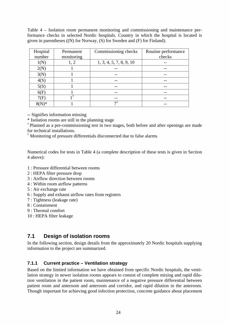
Table 4 – Isolation room permanent monitoring and commissioning and maintenance per-formance checks in selected Nordic hospitals. Country in which the hospital is located is given in parentheses ((N) for Norway, (S) for Sweden and (F) for Finland).
Hospital number
Permanent monitoring
Commissioning checks Routine performance checks
1(N) 1, 2 1, 3, 4, 5, 7, 8, 9, 10 -- 2(N) 1 -- -- 3(N) 1 -- -- 4(S) 1 -- -- 5(S) 1 -- -- 6(F) 1 -- -- 7(F) 1† -- --
8(N)* 1 7¤ -- -- Signifies information missing * Isolation rooms are still in the planning stage ¤ Planned as a pre-commissioning test in two stages, both before and after openings are made for technical installations. † Monitoring of pressure differentials disconnected due to false alarms Numerical codes for tests in Table 4 (a complete description of these tests is given in Section 4 above): 1 : Pressure differential between rooms 2 : HEPA filter pressure drop 3 : Airflow direction between rooms 4 : Within room airflow patterns 5 : Air exchange rate 6 : Supply and exhaust airflow rates from registers 7 : Tightness (leakage rate) 8 : Containment 9 : Thermal comfort 10 : HEPA filter leakage
7.1 Design of isolation rooms In the following section, design details from the approximately 20 Nordic hospitals supplying information to the project are summarized.
7.1.1 Current practice – Ventilation strategy Based on the limited information we have obtained from specific Nordic hospitals, the venti-lation strategy in newer isolation rooms appears to consist of complete mixing and rapid dilu-tion ventilation in the patient room, maintenance of a negative pressure differential between patient room and anteroom and anteroom and corridor, and rapid dilution in the anteroom. Though important for achieving good infection protection, concrete guidance about placement

25
of supply and exhaust registers in a patient room, anteroom and bathroom in an isolation suite is generally lacking in today’s isolation room guidelines. Probably in large part because of this, placement and number of supply and exhaust registers in isolation room suites varies widely in Nordic hospitals today.
7.1.2 Current practice – Ventilation parameters In the following section, the limited data appearing in Table 3 are supplemented with addi-tional information from these and other Nordic hospitals that were not included in the table. 7.1.2.1 Pressure differentials Design pressure differentials between patient room and corridor varied widely in the Nordic hospitals from which we received information. At one end of the scale, in one hospital, rooms designated for airborne infection isolation use were not known to have been specifically de-signed for negative pressure. On the other end of the scale, two hospitals in Sweden (See Ta-ble 3 above) had a patient room-corridor design pressure differential of 50 Pa. 7.1.2.2 Ventilation supply air volume (outside air) Design ventilation supply air represented about two-thirds of the total air change rate in pa-tient rooms (with the remainder coming from the anteroom) and one-half of the total air change rate in anterooms (with the remainder coming from the corridor) in the two hospitals where we have information in Table 3 above. 7.1.2.3 Ventilation exhaust-supply airflow differential rate Design within-room exhaust-supply airflow differentials within isolation rooms varied widely in the Nordic hospitals from which we received information. At one end of the scale, in one hospital, rooms designated for airborne infection isolation use were not known to have been designed with an exhaust-supply airflow differential. On the other end of the scale, one hospi-tal in Norway (see Table 3 above) had a design exhaust-supply differential of 250 m3/h in one isolation room (Hospital 1). This resulted in a ventilation exhaust flow rate 38% greater than the supply rate to the room. Exhaust airflow rates were 50% greater than supply airflow rates in anterooms in this hospital. 7.1.2.4 Air exchange rate Design air exchange rates ranged from 5 to 21 per hour in patient rooms (from six hospitals) and from 10 to 47 in anterooms (from four hospitals) in Table 3 above. In other hospitals, most isolation rooms had design air exchange rates ranging from 6 to12. 7.1.2.5 Planned leakage (controlled air path) The importance of planned leakage in the form of a controlled air path was a design consid-eration in at least one of the hospitals (Hospital 1 in Appendix) providing basis material for this report. 7.1.2.6 Unplanned envelope leakage More and more focus is being placed on design for good envelope tightness (and a minimal air leakage rate), without which adequate pressure differentials between room, anteroom and corridor will be difficult to achieve upon commissioning and to maintain over time. A newer option is for hospitals to buy prefabricated isolation rooms in which a maximum level of un-

26
planned envelope leakage (or tightness specification) is contractually agreed upon between the hospital and manufacturer. 7.1.2.7 Thermal comfort The importance of thermal comfort was acknowledged during commissioning testing in at least one of the hospitals (Hospital 1, see Table 4 above), though we do not have any informa-tion about whether draught risk was explicitly considered in any of the isolation room projects at the design stage.
7.1.3 Current practice – Related considerations Limited information was obtained about current practice in Nordic hospitals regarding related considerations to ventilation system design for containment in isolation room suites. 7.1.3.1 Use of HEPA filters on ventilation exhaust and supply air Design for adequate access to HEPA filters both for safe replacement and for periodic per-formance checking was included in at least one Nordic hospital represented in this study (Hospital 1 in Tables 3 and 4 above and in Appendix A below). 7.1.3.2 Sealability for fumigation Sealability for fumigation as a design issue was included in at least one Nordic hospital repre-sented in this study (Hospital 1 in Tables 3 and 4 above and in Appendix A below). In order that a sealable patient room could be achieved at the same time that a controlled air path was assured when the doors to the isolation suite were closed, bypass ducts with sealable dampers were installed between the patient room and anteroom and anteroom and corridor. The con-trolled air path was thus provided by the bypass ducts. 7.1.3.3 Cleanability Design for optimum cleanability was included in at least one Nordic hospital represented in this study (Hospital 1 in Tables 3 and 4 above and in Appendix A below).
7.1.4 Current practice – Control strategy Limited information was obtained about current practice in Nordic hospitals regarding the control strategy for ventilation systems in isolation room suites. For Hospital 1, pressure con-trol was implemented while for Hospital 8, constant air supply volume and constant exhaust-supply differential volume was chosen.
7.2 Performance checking of isolation rooms A systematic, comprehensive and commonly accepted testing protocol is at present lacking for commissioning and periodic performance testing of negative pressure isolation rooms in Nordic hospitals. This is evidenced by the general lack of information appearing in Table 4 above. Commissioning tests appear to be defined individually in each case, based on require-ments set forth by the hygiene experts at the hospital involved and developed in consultation with the ventilation contractor responsible for the project. The nature and content of the test-ing (including acceptance criteria) are therefore highly dependent on the knowledge and pref-erences of these professionals.

27
7.2.1 Current practice – Permanent monitors Some type of permanent visual indicator that a pressure differential exists between corridor, anteroom and patient room appears to be a standard feature in new or planned isolation rooms in Nordic hospitals today. We did not obtain any information about whether permanent moni-tors for exhaust HEPA filter pressure drop and supply and exhaust air volumes are currently in use in Nordic hospitals.
7.2.2 Current practice – Commissioning (start-up) We obtained few details about specific commissioning procedures performed at individual Nordic hospitals. In at least one case (Hospital 1 above and in Appendix A below), airflow direction between rooms, within-room airflow patterns, air exchange rates (using tracer meth-ods), envelope tightness, containment and thermal comfort tests were performed upon com-missioning. Tightness testing appears to be becoming more prevalent as part of commissioning testing for planned isolation rooms in Norway, as the importance of adequate tightness in achieving and maintaining a high pressure differential has been realized (See for example the description of tightness testing planned for Hospital 8 in Appendix A). There is no common guidance, how-ever, about the level of tightness required to achieve and maintain an adequate pressure dif-ferential, and about how to satisfactorily demonstrate this in a tightness test.
7.2.3 Current practice – Routine performance monitoring We did not obtain any details about specific routine performance monitoring procedures at individual Nordic hospitals

28
8. Best practice Best practice in this instance refers to our interpretation of best practice with regard to design and performance testing of isolation room suites, in part based on the review above of current and pertinent guidelines, standards, and regulations; in part based on the evaluation above of the scientific evidence behind these guidelines, standards and regulations; and in part based on the review above of current practice in Nordic hospitals.
8.1 Design of isolation rooms
8.1.1 Best practice – Ventilation strategy Of all of the isolation room guidelines evaluated for this report, ASHRAE [14] gives the most detailed guidance regarding ventilation strategy, and appears to represent current best practice in this area. Though a laminar, directional air flow is a proven technology in clean room ap-plications, the air flow rates in isolation rooms are too low to allow for effective directional flow from a health care giver at one side of the patient room to the patient bed and out of the room. The most effective ventilation strategy is, in practice, to try to achieve effective mixing and contaminant dilution so that risk of exposure is minimized for isolation room occupants. In addition, an important aspect of the ventilation strategy is to create and maintain a con-trolled air path into the patient room. This is not possible if the windows in the isolation room can be opened. Exhaust registers should be located as close to the patient’s head as is practical, as removal at the source is the best strategy for optimising contaminant control. This must not be at the ex-pense of thermal comfort and acceptable noise levels for the patient, however. To enable achievement of a very high air exchange rate and efficient contaminant removal in an anteroom, both supply and exhaust registers should be included within the anteroom.
8.1.2 Best practice – Ventilation parameters The following is a closer look at best practice in design values for ventilation parameters im-portant to isolation room performance 8.1.2.1 Pressure differential between rooms (door closed) There is presently no direct evidence that between-room pressure differentials of greater than 10 Pa yield any significant containment improvement in isolation suites in hospitals. This would imply an isolation room suite pressure differential (patient room-anteroom-corridor) of 20 Pa. In other words, isolation suite pressure differentials of 30 Pa, 40 Pa and even 50 Pa have not been shown to be better than 20 Pa. A very high pressure differential may in fact increase turbulence from door opening, which could conceivably reduce the level of contain-ment of an isolation room suite. Exactly at what pressure differential this could become an issue is not well defined. Taking Nordic and international standards and guidelines for isola-tion rooms and clean rooms into consideration, patient room-anteroom and anteroom corridor pressure differentials of 10-15 Pa, for a total patient room-corridor isolation suite pressure differential of 20-30 Pa represent best practice for in-service isolation rooms at present. De-sign (and commissioning) values, then, of 15 Pa for both patient room-anteroom and ante-

29
room-corridor pressure differentials allow for substantial variations in pressure differentials through the year in the event that a control strategy maintaining constant supply air volume and constant exhaust-supply differential volume is chosen (see 8.3 below). Some design strategies for achieving and maintaining a high pressure differential between an isolation room, an anteroom and a corridor (in addition to ensuring that the rooms are as air-tight as possible):
1. Timber doors bend in time under the force and lift off the seals. Rigid aluminium or fibreglass doors with glass viewing panels seem best.
2. Large doors give large door opening forces and these are often difficult to overcome by nursing staff with items in their hands. Automatic or powered doors are therefore preferable.
3. An interlock on the doors to ensure that the door between corridor and anteroom and anteroom and patient room cannot be opened at the same time.
4. A sliding entry door may be preferable to a swinging door (sliding doors may however result in an unacceptably large air leakage, as the sliding components are difficult to seal). In case a swinging door is used, the pressure differential should force the door into (and not away from) the seal. In other words, doors should open outwards going into a negative pressure isolation room suite.
8.1.2.2 Ventilation supply air volume (outside air) As is discussed above, many of the isolation room guidelines examined in this report do not make a clear distinction between total air exchange rate and outside air exchange rate in isola-tion rooms and anterooms. In a case where a distinction is made (ref. [14]), the outside air exchange rate is recommended to be a minimum of two per hour for the patient room and two in the anteroom, suggesting (at minimum) modest ventilation supply airflows to the patient room and the anteroom, assuming no recirculation of exhaust air. Complete mixing and high ventilation effectiveness throughout a zone are, however, facilitated by a high supply air ven-tilation rate. An outside air ventilation rate corresponding to approximately 10 outside air ex-changes in the patient room and 20 outside air exchanges in the anteroom, in conjunction with the ventilation exhaust-supply airflow differentials discussed in section 8.2.2.3 below, yields total air exchange rates (see 8.2.2.4 below) that are consistent with good containment as well as with maintenance of an acceptable thermal comfort, and therefore represent current best practice. 8.1.2.3 Ventilation exhaust-supply airflow differential rate Best practice includes design for a substantial within-room exhaust-supply airflow differential (coupled with a controlled air path) in the patient room and anteroom to ensure airflow into the isolation suite and thereby to maximize containment performance. Taking international guidelines and current practice into account, a patient room exhaust-supply airflow differen-tial of 200-250 m3/hr and an anteroom exhaust-supply airflow differential of about 200 m3/hr (ensuring a very high air exchange rate in the anteroom) represents current best practice. 8.1.2.4 Air exchange rates As high a total air exchange rate as is feasible and compatible with an acceptable thermal comfort in a patient room is desirable to protect healthcare workers who must enter and work in the isolation suite. Rapid contaminant dilution and removal from the patient room also minimizes potential contaminant transfer out of the patient room when a person leaves the room. Commissioning tests of thermal comfort in Hospital 1 (in Appendix A below) demon-

30
strated that draught risk at the location of the patient bed in a room was low in isolation rooms with total air exchange rates of 15-21 per hour. Taking this and Nordic and other standards and guidelines for isolation rooms and clean rooms into consideration, a fresh air exchange rate of about 15 represents current best practice for the patient room. As tracer testing has repeatedly shown that some tracer gas will escape from an isolation room suite into the corri-dor when a person leaves even at a patient room-corridor pressure differential of 30 Pa, a very high air exchange rate (greater than 40) in the anteroom is a good strategy for maximizing containment performance of the suite as a whole. As the anteroom is a relatively small vol-ume in relation to the patient room, this can be achieved at relatively modest flow rates (and correspondingly, operating costs). 8.1.2.5 Planned leakage (controlled air path) Best practice includes design for a controlled air path into the anteroom and patient room of an isolation room suite. For reference, a leakage area of about 30 cm2 was sufficient to allow for the transfer of 200-250 m3/hr from corridor to anteroom and anteroom to patient room with pressure differentials of 15 Pa between corridor and anteroom and 15 Pa between ante-room and patient room in isolation rooms in hospital 1 in Table 3 above. The ASHRAE guidelines [14] also provide a formula for estimating air leakage area from air leakage volume (flow rate) and pressure differential. 8.1.2.6 Unplanned envelope leakage Best practice includes design and construction for good envelope tightness. The envelope must be solid enough to withstand constant under pressure over many years and must be con-structed in a way that the envelope will not be subjected to appreciable thermal expansion and contraction from seasonal temperature variations that could lead to cracks and increased leak-age over time. Otherwise adequate pressure differentials between room, anteroom and corri-dor will be difficult to maintain. This can be achieved using enclosed plasterboard (gypsum) ceilings, well-sealed penetrations and tight-fitting doors and windows. An example listing of construction details and a protocol to follow to ensure adequate isolation room tightness is given in Appendix B. 8.1.2.7 Thermal comfort Best practice includes design for an acceptable thermal comfort as defined in ISO 7730 [1].
8.1.3 Best practice – Related considerations Best practice includes consideration at the design stage of factors that are related to ventila-tion and isolation room performance. 8.1.3.1 Use of HEPA filtration HEPA terminals have to be built so that they can be tested. Supply and exhaust filters must in practice be tested using two different methods. Supply filters are tested with a scanning method. This requires an access point upstream of the filter so that the challenge aerosol can be injected. In addition, the HEPA filter terminals must be provided with sampling points so that the upstream aerosol concentration can be determined. Exhaust HEPA filters cannot gen-erally be scanned in the same way as a supply filter unless the filter surface is accessible on the downstream side of the filter. Alternately, exhaust filters are tested using an overall leak test for filters mounted in ducts or air handling units. For testing of exhaust HEPA filters, challenge aerosol can be released at one of the exhaust registers. The filter itself (which should be Safe Change) must be equipped with sampling points such that the upstream con-

31
centration can be determined. Downstream of the filter in the duct system there must be at least one measurement point, for example a curved tube in the direction of the flow, so that the concentration of aerosol can be measured and quantified in case of leakage. Comprehen-sive information about HEPA filter testing is given in reference [2]. The exhaust side filter must be able to be changed in a safe manner, and the duct length be-tween the exhaust register(s) and HEPA filter should be as short as possible and should be able to be fumigated (and therefore should be gastight). A good way to do this is to allow ac-cess to the filter(s) from a cabinet in the isolation room. A bad way to do this is to place the filter(s), for example, in the above the ceiling where access is difficult and service personnel may run the risk of damaging filter bags during removal. Correct installation of new filters requires ample space so that the filter can be adequately tightened. A pre-filter must be used upstream of the exhaust HEPA filters to prevent rapid clogging of the exhaust HEPA filters. In some instances, a fine mesh net has been used on the exhaust register as a dust filter. This has not proven to be a good solution, as the net represents a very small area for dust collection and therefore can become rapidly clogged. Use of a bag filter, for example and EU9 filter, appears to be a better alternative, as it provides a much larger surface area (and therefore capacity) for collection of large quantities of textile fibres and other particles before the pressure drop becomes significant. 8.1.3.2 Sealability for fumigation The likelihood of the need to seal an isolation room for fumigation should be assessed. The possibility that appropriate sealing for fumigation could be achieved if necessary through use of tape and plastic to cover controlled air paths should be considered. Use of gastight dampers on supply and extract ducts, however, is desirable as it allows for airing out the disinfectant after fumigation without having to go into the room and manually uncover the supply and exhaust registers. 8.1.3.3 Cleanability Important design details representing best practice for achieving optimum cleanability in iso-lation rooms include:
• Smooth cleanable surfaces resistant to chemical agents for cleaning and disinfec-
tion • Rounded corners for the floor, wall & ceiling • Smooth junction between floor and wall • Minimizing horizontal surfaces.
8.1.4 Best practice – Control strategy Control by maintaining a constant ventilation supply volume and constant supply-exhaust differential volume implies that the patient room-anteroom pressure differential and ante-room-corridor pressure differential will be allowed to vary over time. This will not be a prob-lem if the commissioning level pressure differences are high enough so that minimum pres-sure differentials (doors closed) can be upheld throughout the year and in the event of non-transitory disturbances (disturbances other than opening of isolation suite doors) affecting isolation suite ventilation. The relative simplicity of this approach is a strong argument for its use as a best practice control strategy in this application.

32
On the other hand, pressure is easy to monitor and relatively easy to use as a control variable, and therefore system function is in practice easy to follow up over time. One strategy using dynamic control of air volumes would be to use a constant air volume (CAV) unit on the sup-ply side (in the event that HEPA filtration is used on the supply air, then the CAV unit can probably be dropped, as the supply side is likely to be hydraulically very stable) with the total exhaust volume (patient room/anteroom/bathroom) adjustable to maintain the desired pressure differential. In this way the anteroom under pressure will follow the patient room under pres-sure, and there is no need to provide separate exhaust regulation for the patient room and ante-room. Though the supply air volume may not be regulated in this approach, monitoring of supply air volume would still be desirable.
8.2 Performance checking of isolation rooms Best practice in performance checking of isolation rooms implies that a combination of per-manent monitors and appropriate measuring equipment for performing transient testing are available, and that the monitors and equipment are used in a commissioning test upon deliv-ery of the finished product and then periodically afterwards for routine performance monitor-ing to ensure that isolation room function remains satisfactory over time.
8.2.1 Permanent monitors The following is a listing of the permanent monitors that should be included to achieve best practice in isolation room performance checking. Also included is a justification for inclusion of each monitor. 8.2.1.1 Pressure differential monitor with alarm Some type of permanent visual indicator that a pressure differential exists between corridor, anteroom and patient room, and an audible or visual alarm that is actuated when the pressure differential is lost or insufficient, represents best practice. The reading on the indicator should be logged, either manually or electronically, and available for review. Justification: Corridor-anteroom and anteroom-patient room pressure differentials are impor-tant facets of containment in isolation rooms. Permanent monitors for checking whether a pressure differential exists between rooms are readily available, either as pressure transducers or as airflow direction indicators. Review of the pressure differential record over time is an important element of routine performance monitoring (see below) and can represent a valu-able diagnostic tool in case of problems. 8.2.1.2 HEPA filter pressure drop monitor on exhaust side Pressure drop on the exhaust HEPA filter should be permanently monitored and logged, and the data should be accessible. Justification: A clogged HEPA filter on the exhaust side of the isolation room can mean that isolation performance is compromised. With a permanent monitor showing the exhaust HEPA-filter pressure drop, a clogged HEPA filter can be quickly discovered and replaced. A clogged filter on the supply side is less likely and less critical for isolation room containment performance. Periodic checking of the HEPA filter pressure drop is an important element of routine performance monitoring and can represent a valuable diagnostic tool in case of prob-lems.

33
8.2.1.3 Supply and exhaust air volume monitors In the event that the control strategy involves a constant supply volume and a constant ex-haust supply volume differential, then permanently installed supply and exhaust volume monitors in isolation suite ductwork may not strictly be necessary, though these would still be desirable for monitoring system performance.
8.2.2 Commissioning (start-up) Detailed and comprehensive requirements for commissioning (start-up) tests are not provided in any of the isolation room guidelines that we have examined in this report. Furthermore, no international standard methods presently exist for commissioning of hospital isolation rooms. An important aspect of the commissioning process is to define acceptable ranges for the measured values of the parameters that are to be quantified during commissioning and later in routine performance monitoring checks. Adequate documentation is essential for demonstrating satisfactory performance in a commis-sioning test for a new isolation room or for an isolation room that must be recommissioned as a condition for demonstration of continued acceptable performance (see 8.3.3 below). An in-ternational standard for commissioning of cleanrooms (see ref [28]) can provide guidance about adequate documentation regarding testing and approval. The following is a listing of parameters that should be checked and documented to achieve best practice in demonstration of adequate airborne infection containment performance during isolation room commissioning. Also included is a justification for inclusion of each item. 8.2.2.1 Pressure differential between rooms The pressure differential (door closed) between corridor and anteroom and corridor and pa-tient room should be checked on the permanent monitors (described in 4.1.1 above) and the results documented. Justification: Pressure differential is an important measure of containment between rooms. Documentation of pressure differentials at start-up sets the benchmark for evaluating system performance over time. 8.2.2.2 Airflow direction between rooms (door open) The airflow direction between corridor and anteroom and anteroom and patient room should be checked, with one door open at a time, using one of the testing methods described in 4.2.1 above, and the results documented. Justification: Airflow direction is an important measure of containment between rooms. Documentation of airflow directions at start-up sets the benchmark for evaluating system per-formance over time. 8.2.2.3 Within-room airflow patterns The airflow pattern within the patient room should be checked to ensure that there are no stagnant areas and that short-circuiting from supply to extract registers is not occurring, using one of the testing methods described in 4.2.2 above, and the results documented.

34
Justification: Airflow pattern within the patient room is an important facet of containment within the patient room. Documentation of airflow pattern within the patient room at start-up sets the benchmark for evaluating system performance over time. 8.2.2.4 Air-exchange rate The air exchange rate in the patient room and anteroom should be checked using one of the testing methods described in 4.2.3 above, and the results documented. Justification: Air exchange rate is an important measure of contaminant dilution, which in itself is an important measure of containment in an isolation room suite. Documentation of patient room and anteroom air-exchange rates at start-up sets the benchmark for evaluating system performance over time. 8.2.2.5 Supply and exhaust air volumes from registers Supply and exhaust airflow rates should be checked in all registers in the anteroom, patient room and bathroom, if possible, using one of the testing methods described in 4.2.4 above, and the results documented. Justification: Supply and exhaust air volumes from registers are important measures of whether the ventilation system performs as designed. Documentation of supply and exhaust airflow rates at start-up sets the benchmark for evaluating system performance over time. 8.2.2.6 Tightness (leakage rate) The tightness of the patient room should be checked using one of the testing methods de-scribed in 4.2.5 above, and the results documented. Justification: Measurement of tightness is important for determining whether sealing meas-ures have been adequate. Documentation of tightness at start-up sets the benchmark for evalu-ating change in tightness over time in the event that a tightness test is necessary at a later date. 8.2.2.7 Containment The containment of the isolation room suite should be checked using one of the testing meth-ods described in 4.2.6 above, and the results documented. Justification: Adequate containment under the challenge of a person or persons exiting an isolation room is a principal purpose of an isolation room suite. Documentation of contain-ment at start-up sets the benchmark for evaluating change in containment performance over time. 8.2.2.8 Thermal comfort Thermal comfort conditions should be checked at the patient bed using one of the testing methods described in 4.2.7 above, and the results documented. Justification: Measurement of thermal comfort parameters is important for determining whether the ventilation system performs as designed. Documentation of thermal comfort at start-up sets the benchmark for evaluating system performance over time. 8.2.2.9 HEPA filter leakage HEPA filter leakage should be checked for all HEPA filters in the isolation room ventilation system using one of the testing methods described in 4.2.8 above, and the results documented.

35
Justification: HEPA filters cannot perform their intended function if there are air leakages through or around the filters. 8.2.2.10 HEPA filter pressure drop Pressure drop should be checked across all HEPA filters in the isolation room ventilation sys-tem, either by observing pressure readings on permanently installed monitors, or by using a portable pressure gauge, and the results documented. Justification: Measurement of HEPA filter pressure drop is important for determining whether the ventilation system performs as designed. Documentation of HEPA filter pressure drop at start-up sets the benchmark for evaluating system performance over time.
8.2.3 Routine performance monitoring Recommendations for routine performance monitoring to demonstrate continued proper func-tion are included in varying degrees of detail in most of the isolation room guidelines evalu-ated in this report. There are no international standards as yet available, however, that cover this area. An international standard does exist, however, for demonstrating continued compliance of cleanrooms [31]. Continued compliance is demonstrated in this standard through routine per-formance monitoring. Routine performance monitoring test results that are within specified limits signify that a cleanroom is in a condition of continued compliance. If results from one or more routine performance checks are outside of acceptable limits, then the cleanroom is said to be out of compliance. Cleanrooms must be requalified (recommissioned) after an out-of-compliance condition is corrected. In the absence of an international standard for isolation room continued compliance, we adopt a similar approach here. The following is a listing of parameters that should be checked and documented to achieve best practice in routine performance monitoring for demonstration of continued adequate iso-lation room suite containment performance. Also included is a recommendation for the fre-quency of each check (with justification) and a justification for inclusion of each check in a routine performance monitoring protocol. If the results of the checks are within the limits specified (as agreed upon between customer and supplier), then the isolation room suite is considered to be in an acceptable condition. In the course of routine performance monitoring, in the event that one of the measured parameters falls outside of the acceptable range (as agreed upon between customer and supplier) for that parameter, then the isolation suite could be considered to be in an unacceptable condition. In this case, an action plan should be speci-fied. The action plan could involve further diagnostic tests and steps to return the parameter into the acceptable range for adequate containment performance. Best practice implies that recommissioning of an isolation room suite is undertaken after remedial action to correct an unacceptable condition, or in the event that the operational use of the room changes signifi-cantly from the design specification, in agreement with ref. [31]. 8.2.3.1 Pressure differential between rooms The pressure differential (door closed) between corridor and anteroom and corridor and pa-tient room should be checked on permanently installed monitors (described in 4.1.1 above) and the results documented. In addition, the performance of the pressure differential monitor

36
should be verified at an interval not greater than 12 months, in connection with the tests in 8.2.3.3 and 8.2.3.4 described below. Frequency: No less than once per month when an isolation room is empty, and once per day when it is occupied, in agreement with ref. [11]. Justification: Checking and recording the pressure differential can be done quickly and easily, in addition to the justification provided in 8.2.1.1 above. 8.2.3.2 HEPA filter pressure drop on exhaust side The HEPA filter pressure drop on the exhaust side of the ventilation system should be checked on permanently installed monitors (described in 4.1.2 above) and the results docu-mented. Frequency: At an interval not greater than one month, in conjunction with the pressure differ-ential check described above. Justification: An acceptable HEPA filter pressure drop on the exhaust side can be critical for maintaining adequate containment in an isolation room suite. If the pressure drop is too high, exhaust airflow rates, pressure differentials and air change rates can be adversely affected. 8.2.3.3 Air exchange rate The total air exchange rate using one of the methods described in 4.2.3 should be measured in the patient room as part of routine performance monitoring, and the results documented. Frequency: At an interval not greater than 12 months. Though ref. [15] recommends an inter-val not greater than 13 weeks for checking of air change rate, provided that the tests in 8.2.3.1 and 8.2.3.2 yield values that are continually within specified limits, then an interval of 12 months is acceptable for this test. Justification: Total air change rate in the patient room is a critical measure of containment, and can be highly dependent on changes in supply and extract airflow rates in the ventilation system, as well as on infiltration and exfiltration airflow rates. 8.2.3.4 Supply and exhaust rates from registers In the event that supply and exhaust registers are readily accessible for measurement of air-flow rates using one of the methods described in 4.2.4 above, they should be measured as part of routine performance monitoring, and the results documented. Frequency: At an interval not greater 12 months, in agreement with ref. [31]. Though ref. [15] recommends an interval not greater than 13 weeks for checking supply air and exhaust quanti-ties, provided that the tests in 8.2.3.1 and 8.2.3.2 yield values that are continually within specified limits, then an interval of 12 months is acceptable for this test. Justification: Adequate supply and exhaust airflow rates from registers are primary indicators that the ventilation system is continuing to perform as expected. 8.2.3.5 Airflow direction between rooms and within-room airflow patterns Airflow visualization should be performed in accordance with the methods described in 4.2.1 and 4.2.2 as part of routine performance monitoring, and the results documented.

37
Frequency: At an interval not greater than two years, in agreement with ref. [31]. Justification: Airflow visualization is an important qualitative check of continued acceptable isolation room performance and can be done relatively easily. 8.2.3.6 Containment Containment using one of the methods described in 4.2.6 should be measured in the isolation suite as part of routine performance monitoring, and the results documented. Frequency: At an interval not greater than two years, in agreement with ref. [31]. Justification: Adequate containment under the challenge of a person or persons exiting an isolation room is a principal purpose of an isolation room suite, and can be measured directly relatively easily. 8.2.3.7 Installed HEPA filter leakage HEPA filter leakage should be measured using the method referenced in section 4.2.8 as a part of routine performance monitoring, and the results documented. Frequency: At an interval not greater than two years, in agreement with ref. [31]. Though ref. [11] recommends every six months for the HEPA filter leakage test, this reference also allows for the use of HEPA filtered return air in the hospital ventilation system. As recirculation of isolation room exhaust air is not used in Nordic hospitals, this test is perhaps less critical for demonstrating a continued healthy work environment in Nordic hospitals and therefore can be performed semi-annually. Justification: Absence of leakage through or around HEPA filters in the ventilation system is important for ensuring the effectiveness of HEPA filters as containment measures in isolation room suite ventilation ducting.

38
References [1] ISO 7730: Moderate thermal environments, Determination of the PMV and PPD indices and specification of the conditions for thermal comfort. European Committee for Standardiza-tion, 1994. [2] ISO 14644-3: Cleanrooms and associated controlled environments: Part 3 - Metrology and test methods. European Committee for Standardization, 2001. [3] Wiseman B (2003). Room pressure for critical environments. ASHRAE Journal. February 2003, 34-39. [4] EN-ISO 12569: Thermal insulation in buildings – Determination of air change in build-ings – Tracer gas dilution method. European Committee for Standardization, 2001. [5] Pavelchak N, Palmer W, DePersis RP, London MA (2002). A simple and inexpensive method for determining the effective ventilation rate in a negatively pressurized room using airborne particles as a tracer. Applied Occupational and Environmental Hygiene, 17(10), 704-710. [6] Decker J (1995). Evaluation of isolation rooms in health care settings using tracer gas analysis. Applied Occupational and Environmental Hygiene, 10(11), 887-891. [7] EN 13829: Thermal performance of buildings – Determination of air permeability of buildings – Fan pressurization method (ISO 9972:1996, modified). European Committee for Standardization, 2000. [8] Rydock JP (2002). A simple method for tracer containment testing of hospital isolation rooms. Applied Occupational and Environmental Hygiene, 17(7),1-5. [9] Rydock JP, Eian PK (2004). Containment testing of isolation rooms. Journal of Hospital Infection, 57(3), 228-232. [10] ISO 7726: Thermal environments, Instruments and methods for measuring physical quantities. European Committee for Standardization, 1993. [11] Centers for Disease Control and Prevention. Guidelines for preventing the transmission of Mycobacterium tuberculosis in health-care facilities (1994). MMWR 43(RR13). [12] Centers for Disease Control and Prevention. Guidelines for environmental infection con-trol in health-care facilities (2003). MMWR 52(RR10), 1-42. [13] American Institute of Architects and The Facilities Guidelines Institute. Guidelines for design and construction of hospital and health care facilities, ISBN 1-57165-002-4. American Institute of Architects Press, Washington, DC, 2001. [14] American Society of Heating, Refrigerating and Air-Conditioning Engineers, Inc. HVAC design manual for hospitals and clinics, ISBN 1-931862-26-5.ASHRAE, Atlanta, USA, 2003.

39
[15] Dept. of Human Services, Victoria, Australia. Guidelines for the classification and de-sign of isolation rooms in health care facilities, July 1999. [16] Queensland Health, Australia. Capital works, Building and refurbishment: Infection con-trol guidelines, September 2002. [17] National Institute of Public Health (Norway). Isoleringsveilederen: Bruk av isolering av pasienter for å forebygge smittespredning i helseinstitusjoner (2004). ISBN 82-82-072-8. [18] Statens Serum Institut (Denmark). Anbefaling vedrørende type og indretning af isolationsenheder, der kan bruges til patienter med smitsomme sygdomme og som tilfredsstiller kravene til isolering ved luftbåren smitte, Ref. 2974-37, 30 December 2003. [19] The Interdepartmental Working Group on Tuberculosis, UK Dept. of Health. The pre-vention and control of tuberculosis in the United Kingdom, September 1998. [20] Health Canada, Health Protection Branch – Laboratory Center for Disease Control. Guidelines for preventing the transmission of tuberculosis in Canadian health care facilities and other institutional settings (1996). Canada Communicable Diseases Report – Supplement Vol 22SI. [21] Working Committee for Buildings/Engineering of Patient's Bedroom for Infectious Dis-eases. New guideline for planning/design of patient's bedroom for infectious diseases (2003). Health Publications (Translation provided by Mr. Masamitu Ohtsu, Deputy Managing Direc-tor of Isotech Corporation, Japan). [22] Council Directive 90/679/EEC of 26 November 1990 on the protection of workers from risks related to exposure to biological agents at work (seventh individual Directive within the meaning of Article 16(1) of Directive 89/391/EEC. Official Journal of the European Commu-nities - 31.12.90 – Page No L 374/1. [23] Council Directive 93/88/EEC of 12 October 1993 amending Directive 90/679/EEC. Offi-cial Journal of the European Communities - 29.20.93 – Page No L 268/271. [24] Arbeids- og administrasjonsdepartement (Norway). FOR 1997-12-19 nr. 1322: Forskrift om vern mot eksponering for biologiske faktorer (bakterier, virus, sopp m.m.) på arbeidsplassen. [25] Direktoratet for arbeidstilsynet (Norway). Veiledning til arbeidsmiljøloven: Biologiske faktorer. October 1999, revised November 2002. [26] Swedish Association for Hospital Hygiene. Byggenskap och Vårdhygien: Vårdhygieniska aspekter vid ny- och ombyggnation samt renovering av vårdlokaler (2003). [27] Whyte W (2000). Cleanroom Design, 2nd ed. John Wiley & Sons, Chichester, England. ISBN 0471942049. [28] ISO 14644-4: Cleanrooms and associated controlled environments – Part 4: Design, con-struction and start-up.

40
[29] European Committee for Standardization, 2001. European Union Enterprise Directorate General. EC guide to good manufacturing practice revision to annex 1, Manufacture of sterile medicinal products. Brussels, 30 May 2003. [30] EN 12128: Biotechnology – Laboratories for research, development and analysis – Con-tainment levels of microbiology laboratories, areas of risk, localities and physical safety re-quirements. European Committee for Standardization, 1998. [31] ISO 14644-2: Cleanrooms and associated controlled environments – Part 2: Specifica-tions for testing and monitoring to prove continued compliance with ISO 14644-1. European Committee for Standardization, 2000.

Appendix A – Additional information from individual Nordic hospitals Hospital 1 (N): Positions of supply and exhaust locations in newest isolation rooms are as follows:
Key: Supply location Exhaust location Overflow supply from corridor Rooms completed in 2003. All supply and exhaust locations are in the ceiling except exhaust in anteroom which is on the wall (facing bathroom) just above the floor. Overflow supply is to the room only except when room/anteroom door is open, automatically switches to anteroom High inductance supply diffusers with supply air spread out along ceiling in all directions.
Bed
Bathroom Anteroom
Patient room

Results from commissioning tests: Tightness (leakage rate): In each patient room, the air exchange rate at –50 Pa was measured using a tracer (Method 4.3.5.3 described above). Rooms exhibited air exchange rates of 0.14 - 0.36 per hr at the test under pressure, which varied from –52 Pa to –60 Pa. Air exchange rate: In each patient room and anteroom, the recovery time was measured us-ing the tracer decay method (Method 4.2.3.1.1 described above). The results were as shown in Table A1 below. Note: PR2 was the only room exhibiting a recovery time equal to or better than the design criterion. Table A1: Air exchange rates from commissioning tests for isolation rooms in Hospital 1. ‘PR’ denotes patient room, ‘AR’ denotes anteroom.
Room Design air exchange rate (per hour)
Theoretical recovery time
(min.)
Measured recovery time
(min.) PR 1 15 18.4 24.7 AR 1 45 6.1 7.9 PR 2 20 13.8 11.2 AR 2 45 6.1 8.4 PR 3 21 13.1 17.5 AR 3 47 5.9 6.6 PR 4 20 13.8 16.3 AR 4 44 6.3 6.7
Containment: Containment was measured in the isolation room suites using the tracer point release method (Method 4.2.6.1 described above). The results were as follows: Table A2: Calculated dilution factors in anterooms and corridor when a technician exits a patient room at two minutes after tracer release and then exits anteroom 5 minutes after release.
Isolation room Suite number
Dilution factor in anteroom At 5 minutes after tracer release
Dilution factor in corridor at 10 minutes after tracer release
1 152 3110 2 122 1260 3 211 3670 4 125 1280
Containment is expressed as dilution factors in the anteroom and corridor, and represents the ratio of the concentration in the anteroom/corridor to the calculated concentration in the pa-tient room at the time the testing technician first left the patient room two minutes after the tracer release, assuming complete and instantaneous mixing of the tracer in the room. Thermal comfort: Draught rating was measured 30 cm above the patient bed and at different points around the room at 80 cm above the floor, with the acceptance criterion that the draught rating should not exceed 10% at any of the measurement points. The calculated draught rating ranged from 0.0% – 9.8% and the air velocity ranged from 0.033 – 0.072 m/s for the 10 measurement points.

Hospital 2 (N): Isolation rooms with this design came into service in 1999. Dimensions patient room + bath-room + anteroom: 20 m3 + 5 m3 + 5.5 m3 = 30.5 m3. 10-12 fresh air exchanges per hour. Design pressure differences: Patient room-corridor: -30 Pa Anteroom-corridor: -15 Pa Manometer plus data logger give record of under pressure in isolation room that is reviewed every day. HEPA filters on both supply and exhaust vents. All supply and exhaust locations are in the ceiling. Separate supply and exhaust fans for each room, no heat recovery. Hospital 3 (N):
Key: Supply location Exhaust location 12 air fresh air exchanges per hour in patient room, 10 in anteroom 15 Pa pressure difference between patient room and corridor (Total of about 320 m3/hr ex-haust air, 200 m3/hr supply). Separate ventilation system for each suite.
Bathroom Anteroom
Patient room

Hospital 4 (S): - Design pressure differences: 25 Pa between anteroom and corridor, 50 Pa between patient
room and corridor - Entrance directly from outside possible through a second attached (external) anteroom. - To minimize risk of transfer of infectious agent to corridor, system designer recommends
that health care personnel always exit patient room through external anteroom - Pressure gauges in corridor display pressure differentials between patient room and each
anteroom as well as patient room and corridor, with audible alarm. - Exhaust from attached bathroom through absolute filter in ceiling. - Supply air through absolute filters in both anterooms. - Overflow ducts (with fire dampers) in the walls between anterooms and patient room and
patient room and bathroom provide supply air to patient room and bathroom. - Interlock mechanism on anteroom doors to ensure that the doors between corridor and an-
teroom and anteroom and patient room cannot be open at the same time. Hospital 5 (S): - Design pressure differences: 25 Pa between patient room and anteroom and 25 Pa between
internal anteroom and corridor, implying 50 Pa between patient room and corridor. - Entrance directly from outside possible through a second attached (external) anteroom - To minimize risk of transfer of infectious agent to corridor, system designer recommends
that health care personnel always exit patient room through external anteroom - Five fresh air changes per hour in patient room - Pressure gauges in corridor display pressure differentials between patient room and each
anteroom as well as internal anteroom and corridor, with audible alarm. - Supply air is through an absolute filter in inner anteroom, exhaust from bathroom through
absolute filter in ceiling - Overflow ducts (with fire dampers) in the walls between the internal anteroom and patient
room and patient room and bathroom provide supply air to patient room and bathroom, respectively.
- Interlock mechanism on anteroom doors to ensure that the doors between corridor and anteroom and anteroom and patient room cannot be open at the same time.
Hospital 6 (F): - Isolation rooms can be pressurized negatively or positively. - Pressurization can be adjusted by a control device. - Pressure difference display in corridor. - Alarm to real estate management. - Pressure difference transmitters are calibrated annually. - No return air, each room has separate ventilating units for supply- and exhaust air and
separate ducts. - HEPA filters for supply- and exhaust air. - Negative pressurization at least 5-10 Pa, according to experience under 5 Pa is not
sufficient.

Hospital 7 (F): - Airflow values in negatively pressurized isolation rooms (supply air-exhaust air): patient
rooms -50 dm3/s, anteroom -35dm3/s, toilet -30 dm3/s. - Air change rate (air changes per hour): patient room 5, anteroom 10. - Common ventilating unit for isolation rooms. - EU 8/9 filters in supply and exhaust. - Too low negative pressurization has caused problems: door opening gives false alarm ->
monitoring of the pressure difference has been removed from service. - Heat recovery by air-to-air cross flow heat exchanger. - Instructions for maintenance of the ventilating unit: annual service, change of the filters
twice per year or according to alarms of the control automation. Hospital 8 (N): - Design air change rates: 12 in patient room, 15 in anteroom, 4 in corridor - Design pressure differentials: patient room – corridor: 20 Pa, anteroom – corridor: 10 Pa - Supply air common for isolation room and patient rooms on same wing - Each isolation suite has separate exhaust, with 2 exhaust fans (one of which is a backup) - Supply and exhaust in anteroom and patient room, exhaust only in bathroom - Airflow rates are regulated, not pressure differentials - Anteroom locking mechanism requires a minimum pressure differential and number of air
exchanges before a person can leave anteroom for corridor after exiting patient room to anteroom.
- Corridor – anteroom and corridor – patient room pressure differentials continuously meas-ured displayed in corridor outside of isolation room suite
- Isolation rooms still in design stage, to be completed in 2006 - Two stage tightness testing planned: both before and after penetrations are established for
technical installations. The following requirements for tightness are proposed, based on the experience of the consulting engineers (Airflow rates are expressed as the maximum al-lowable percent of the difference in the supply/exhaust airflow rates):
Pressure difference
(Pa) % of supply/ exhaust airflow differential
20 15 30 20 50 25

Appendix B – Construction details for adequate isolation room tightness The following is an example of a detailed description (from Hospital 8 above) of how to con-struct an isolation room to achieve adequate tightness. An isolation room construction includes:
• A building frame of rendered concrete • Walls of reinforced stands of thin plate profiles, plywood and two layers of gypsum
plate • A suspended ceiling with one layer of plywood and two layers of gypsum • Surfaces made tight with use of surface sealant • Neutral zones in the walls and above the ceiling
B1. Instructions to follow during isolation room construction process
B1.1 Gypsum walls Mount the walls according to the gypsum manufacturer’s instructions. The walls are made with reinforced frames (1.25 mm), one layer of plywood as a nailing strip and two layers of gypsum. Mounting, caulking, joint spackling and taping of corners as in a smoke-tight room. (See point B2.1).
B1.2 Ceiling Suspended gypsum ceiling (if necessary with a reinforced suspension system) with one layer of plywood (as a nailing strip) and two layers of gypsum, with the outer panel sealed with elastic caulking between the gypsum plate edge and the adjacent walls. Spackling and taping of corners.
B1.3 Technical installations Mounting of technical installations in relation to gypsum panel work follows the usual se-quence. The technical contractor delivers and mounts the equipment for his own installations. Open-ings and nailing strip (studs) are done by the building contractor, after instruction from the technical contractor.
B1.4 Penetrations for cables/pipes and inlaid electrical boxes After the plywood panels (studs) are mounted, the packing frame for gastight penetrations of cables/pipes is installed. Alternatively, this can be a box of stainless steel with gastight pene-trations for electrical cables.

The packing frame/box with flange is mounted in elastic caulking against the plywood and screwed tight. Mill the plywood to a depth equal to the thickness of the flange, such that the outer edge of the flange is in the plane of the plywood. The first layer of gypsum should be mounted with the necessary openings for the cables /pipes that must come into the room. These can if necessary be round openings for standard electrical boxes. The second layer of gypsum hides the flange of the packing frame/box and ensures that the penetration is minimally visible in the room. With use of a standard electrical box, use a type that can be fastened with ‘claws’ to the gypsum panel, and with elastic caulking between the panel and flange on the adjacent stainless steel box. It is important that the penetrations are tested for tightness before the second layer of gypsum is mounted.
B1.5 Penetrations for equipment hanging on internal walls Penetrations are done with a casing with a welded flange for a gastight seal and are mounted with the flange placed in elastic caulking against the plywood. The first layer of gypsum is mounted with the necessary opening for cabling/piping that is to come into the room. Standard cable and pipe penetrations (as used in B1.5 above) can also be used here in the event that the hanging equipment covers the opening. The same type of penetration is also used for water and gas pipes. The dimensions of the opening should be consistent with standard gastight penetrations. Flanges for the different boxes can be made of 1.5 mm stainless steel sheeting and can be placed between the first gypsum layer and the plywood without resulting in visible bulging in the wall surface.
B1.6 Other penetrations Other penetrations of varying sizes such as ventilation registers must have flanges welded too them and then they are mounted between the gypsum layers and sealed with elastic caulking. Drainage pipes must be sealed with elastic caulking. It is important that caulking be done with bottom filling and the bead has the correct shape. Gypsum edges should be sealed and this should be done before the caulking is applied. See points B2.1 and B 2.2.
B1.7 Light fixtures Light fixtures are mounted inlaid in the ceiling. The ceiling is built with a cage over the light-ing fixture, where the cage is prefabricated of 1.5 mm stainless steel or lacquered steel, and is tightness tested before mounting. Electrical supply to the light fixture occurs with a casing for gastight penetration, as is men-tioned in B1.5 above. This means that the ceiling will be completely tight, independent of the type of light fixture used.

B1.8 Openings for doors and windows Openings for doors and windows should be lined with gypsum plates and surface treated in the same manner as a wall. Doors/windows are installed and sealed with elastic caulking. Frames are fixed in place using screws into the caulking.
B1.9 Surface treatment (tight surface) To achieve sufficient tightness, the rooms are to be constructed as wet rooms. The membrane must be as elastic as possible. Scotia moldings are used between the floor and walls, walls and ceiling and interior corners. The floor covering is laid with 900 mm collar along the walls. Surface treatment with prim-ing, gluing of the membrane and the prescribed number of paint coats should be applied be-fore mounting of equipment. Paint with a gloss value of 40 should be used. Internal edges in openings should be treated (sealed) before the elements are installed (doors, internal windows, etc.). Windows in the outer wall should be reinforced with an internal glass pane to ensure an adequate seal against air leakage. This should be mounted and sealed after the edges inside the opening are treated, but before the last coat of paint is applied on the walls. The joint between the wall and floor covering should be spackled and sealed down to 50 mm below the joint. Surface treatment must also be carried out into gastight boxes and should be done in a way that gypsum edges are properly sealed.
B1.10 Caulking It is essential that proper caulking be used.
B2. Instructions for mounting of isolation room elements
B2.1 Order to follow for mounting walls and ceiling, including penetrations
• Mounting of thin plate frames for gypsum walls • Mounting of plywood as a nailing strip, incl. milling for packing frames if necessary • Mounting of penetrations (packing frames, tight box of stainless steel, case with flange for
gastight penetrations, ventilation ducts, etc) with elastic caulking between flange and plywood and between flange and first layer of gypsum
• Mounting of first layer of gypsum • Check of tightness of penetrations, documentation • Extension of cables/pipes into penetrations • Sealing with installation of packing material in gastight penetration frames for ca-
bles/pipes • Sealing with caulking around ventilation ducts/drainage pipes • Temporary sealing of interiors of ventilation ducts /drainage pipes • Check of work done so far, tightness testing and documentation

• Mounting of second layer of gypsum with cutting out of holes for ca-bles/pipes/electrical boxes. Sealing with elastic caulking between all plate layers: gyp-sum plates and plywood and against flanges of gastight boxes, documentation
• Surface treatment applied to all openings • Check of surface treatment, documentation • Mounting of inlaid electric boxes • Pulling of cables • Mounting of technical installations in the room (ventilation, pipes, cable ducts, light
fixtures, etc.) • Mounting switches/electrical outlets with covers • Final check, documentation
B2.2 Order to follow for penetrations in floor elements
• Drill 100 mm diameter holes for water and drainage pipes from sinks and washstands. • Mount pipe cases that are set in concrete and rendered. Use elastic caulking glue
between pipes and casings. • Stainless steel floor flange (deck pipe) with top cover, 100 mm outer diameter and 300
mm high is fixed to the concrete floor. The penetration in the flange cover is sealed with caulking in the space between the cover and the penetrating pipes.
• The concrete flooring and floor covering area adjusted to the deck pipe. Caulking ap-plied between floor and deck pipe.


![[Nordic Built Challenge 17.12.2013] Trine Pertou Mach, Nordic Built: Nordic Built](https://static.fdocuments.in/doc/165x107/547174dcb4af9f980a8b4ad9/nordic-built-challenge-17122013-trine-pertou-mach-nordic-built-nordic-built.jpg)

