Airborne Infection Isolation Rooms - mintie.com for TB.pdf · This manual provides basic...
25
CHAPTER TITLE 87 Airborne Infection Isolation Rooms
Transcript of Airborne Infection Isolation Rooms - mintie.com for TB.pdf · This manual provides basic...
CHAPTER TITLE 87
Airborne InfectionIsolation Rooms
88 TUBERCULOSIS INFECTION CONTROL: A PRACTICAL MANUAL FOR PREVENTING TB
A properly designed and operating AIIR can be an effective infection control measure. Infectious airborne particles are contained within the room, and the concentration of these particles inside the room is reduced.
However, a badly designed and/or incorrectly operating AIIR can place HCWs and other patients at risk for TB infection and disease. In this situation, infectious particles may not be contained in the room, and/or their concentration inside the room may not be effectively reduced. Staff members who rely on such an AIIR may have a false sense of security.
The mechanical elements that make an AIIR effective will deteriorate over time, which may make the controls ineffective. For example, fans can break and ducts can be-come clogged with dust and lint. People who have not been trained in environmental controls may inadvertently adjust or alter the controls. An AIIR that was successfully tested after construction may not be operating correctly a month later. Hence, peri-odic and ongoing assessment of AIIRs is important.
This manual provides basic information about assessing and improving the design and operation of an AIIR. It also includes options to convert an existing patient room into an AIIR and information on guidelines and regulations covering AIIR environmen-tal controls.
TB control in high-risk settings is commonly organized in a hierarchy: administrative (or work practice) controls are the most important, followed by environmental controls, and then respiratory protection. Although this section only addresses environmental controls, all three components should be in place for an effective TB control program.
Whenever an AIIR is used, written policies and procedures should be developed and im-plemented to address the administrative aspects of the AIIR. They should include:
• criteria for initiating and discontinuing isolation
• who has authority for initiating anddiscontinuing isolation
• isolation practices
• how often and by whom the policy and procedure is evaluated
• developing and implementing a written respiratory protection program is also required.
AIRBORNE INFECTION ISOLATION ROOMS (AIIRS)
Designing a New State-of-the-Art AIIR This section describes the requirements and guidelines to be considered when designing a new AIIR, either during new construction or during renovation.
Planning StageDuring the planning stages of a new construction or a remodel project, users often meet with architects to discuss various design elements. This enables the users to provide in-put to the design team. These discussions usually concentrate on the physical layout of the space. The mechanical elements are often left to the mechanical engineer‘s discretion.
Infection control coordinators and other appropriate managers should be included in this process. The infection control aspects of the mechanical system should be addressed so that the people relying on the controls understand this system.
Architects and mechanical engineers may not be aware of some infection control require-ments. While engineers must comply with building codes to get approval for construction and occupancy, they may not be aware of CDC recommendations, or of federal or local OSHA requirements. However, architects and engineers should be familiar and comply with the most current AIA Guidelines for Design and Construction of Hospital and Health Care Facilities and ANSI/ASHRAE Standard for Ventilation for Acceptable Indoor Air Quality.
The mechanical design elements of a new hospital AIIR should, at a minimum, meet all local code requirements, as well as OSHA requirements, CDC recommendations, AIA Guidelines, and ANSI/ASHRAE Standards.
Architectural ConsiderationsArchitecturally, an AIIR should meet all the detailed requirements for a single-patient room, including a dedicated adjacent bathroom.
Architectural design elements should also meet local code requirements. For example, California requirements include:
• Code minimum clearance around the bed
• Code minimum room area
• Windows operable only by use of tools or keys
To increase the effectiveness of negative pressure, the architectural elements should en-sure that the AIIR suite is sealed, except for a half-inch high air gap under the door. To-wards this end, the ceiling should be plaster/sheet rock rather than removable ceiling tiles, and lights should be surface-mounted. Gasketing should be provided at the sides and top of the door, and at ceiling and wall penetrations such as those around medical and electri-cal outlets.
The location of the proposed AIIR should also be considered: areas prone to strong drafts, such as those near elevator banks or doorways, should be avoided if possible.
AIIR doors should be equipped with self-closing devices.
AIRBORNE INFECTION ISOLATION ROOMS 89
The mechanical
design elements of
a new hospital AIIR
should, at a
minimum, meet all
local code
requirements, as
well as OSHA
requirements, CDC
recommendations,
AIA Guidelines, and
ANSI/ASHRAE
Standards.
90 TUBERCULOSIS INFECTION CONTROL: A PRACTICAL MANUAL FOR PREVENTING TB
Determining the Correct Ventilation RateWhen designing the heating, ventilating, and air-conditioning (HVAC) elements of a build-ing, the amount of air supplied to each room is usually selected on the basis of comfort concerns. Unless there are governing code requirements, the engineer will provide venti-lation air as required to keep the space comfortable. This air quantity is usually less than the amount required for effective dilution and removal of infectious particles.
For many spaces in healthcare facilities, such as AIIRs, infection control concerns may be more important than comfort concerns. Engineers should increase the airfl ow rate ac-cordingly. A straightforward way to increase the effectiveness of ventilation is to increase the amount of air moving through a space—in other words, to increase the ventilation rate.
A room’s ventilation rate can be calculated if it has mechanical ventilation. The ventilation rate is usually expressed in air changes per hour (ACH). By calculating the ACH, the room ventilation rate can be compared to published standards, codes, and recommendations. It can also be used to estimate the length of time required to remove infectious particles.
One air change occurs in a room when a volume of air equal to the volume of the room is supplied and/or exhausted. The air change rate in ACH is the volume of air circulating every hour divided by the room volume. Appendix K (page 156) describes air change rates in more detail and demonstrates how to calculate the air change rate of a room that has mechanical ventilation and/or a HEPA fi lter unit.
It is recommended that AIIRs have an exhaust air ventilation rate of at least 12 ACH. This recommendation is consistent with the CDC Guidelines and meets all local requirements known to CNTC.
The ACH is the airfl ow per hour divided by room volume (see Appendix K). For AIIRs, the exhaust airfl ow should be calculated, rather than supply airfl ow. The ACH of the dedi-cated bathroom or anteroom, when present, should be calculated separately from that of the AIIR itself. In other words, only include exhaust air that is exhausted in the AIIR.
Variable Air Volume (VAV) Systems Many mechanical systems do not provide a constant airfl ow rate. These are called vari-able air volume (VAV) systems. They are designed to continually vary the amount of cool-ing or heating air delivered to a room in response to the amount of cooling or heating re-quired. Supply air varies between a fi xed minimum and a fi xed maximum using a VAV box installed in the ductwork. VAV systems are generally not found in hospitals, but are com-mon in buildings that may include clinics.
The volume of air supplied to an AIIR should not vary. Therefore, if an AIIR is to be in-cluded in a building served by a VAV system, the box supplying air to the AIIR should be set to deliver constant airfl ow. The mechanical engineer will need to address comfort control of this room separately.
Locating Supply and Exhaust Ductwork and OutletsThe supply and exhaust location should be chosen to maximize air mixing and to optimize directional airfl ow from the staff member towards the patient. Exhaust should be removed near the possible contamination source.
The best arrangement is to supply air at the ceiling above the foot of the bed, and to ex-haust air on the wall near the fl oor at the head of the bed (where the patient’s head is likely to be).
The supply diffuser should be the louvered blade type, rather than the perforated face type. The diffuser neck size and blow pattern should be selected so that air is directed to all parts of the room. Locate the diffuser where the airfl ow is not obstructed by items such as surface-mounted light fi xtures or a suspended television set.
The bottom of the exhaust grille should be located approximately 6 inches above the fl oor. Because the grille does not direct air, its face pattern is not as important as that of the diffuser. The vertical exhaust duct should be installed in the AIIR wall. An enlarged wall cavity will be required and should be coordinated with the architect. To reduce noise, dampers should be located at a point in the duct far from the outlet. The area in front of the exhaust grille should be kept clear of obstructions, such as furniture and supply carts.
The individual air ducts providing supply and exhaust air for the AIIR suite should have control dampers to adjust the airfl ow quantity. These dampers are usually manually oper-ated, but may be automatic. To ensure access, the handles for the dampers should not be above the AIIR ceiling. They should be either accessible from above the corridor ceil-ing, or remote, tamper-proof handles should be provided in the ceiling or wall of the AIIR.
Maintaining Negative PressureAs described previously (on page 26), negative pressure is achieved when exhaust air exceeds supply air and the room is well sealed except for a gap under the door.
The CDC Guidelines recommend a negative pressure differential of at least 0.01 inches of water gauge (" W.G.).
In practice, an offset this small can be inadequate. Negative pressure may not be consis-tently maintained if there are other external factors, such as fl uctuating air currents caused by elevators, doors, or windows to the outside.
Because smoke may migrate into a room during a fi re, building code offi cials are con-cerned with the amount of air drawn into a room under the door from a corridor. The amount of exhaust air offset from the corridor will need to comply with local codes, which may limit the maximum allowable offset. If the AIIR is equipped with an anteroom, this is-sue will not be as important.
CNTC recommends that the negative pressure differential across the AIIR door be ap-proximately 0.03" W.G. In practice, this may require that the airfl ow offset be adjusted to more than 100 CFM after the room is built, but before it is occupied. Engineers should allow for this possibility in their designs.
AIRBORNE INFECTION ISOLATION ROOMS 91
92 TUBERCULOSIS INFECTION CONTROL: A PRACTICAL MANUAL FOR PREVENTING TB
AIIR with Dedicated Bathroom
Some AIIRs have a dedicated bathroom that is part of the AIIR suite and only for use by the isolated patient. Such AIIRs are more likely to be found in hospitals than in clinics. The advantage of the bathroom is that the patient will not have to open and close the door as often to leave the suite.
To contain odors, the AIIR bathroom should be at negative pressure with respect to the AIIR, where applicable. The bathroom ventilation should comply with local requirements. For example the California Mechanical Code (CMC) mandates an air change rate of 10 ACH, negative pressure, and direct exhaust to the outdoors for bathrooms. In general, an offset of 50 CFM is suffi cient between the bathroom and the AIIR.
Both the AIIR and the combined AIIR and bathroom should be at negative pressure. In other words, not only must the total exhaust for the AIIR plus bathroom exceed the total supply for AIIR plus bathroom, but the AIIR exhaust should also exceed the AIIR supply. This is illustrated in the “Case Study: Dedicated Bathroom” on page 107.
Handling AIIR ExhaustExhaust air removed from AIIRs is likely to contain infectious particles. Consequently, this air should be discharged directly outside the building, where the particles can be diluted by outdoor air and killed by sunlight.
While not included as a minimum recommendation by the CDC Guidelines, the optimum type of exhaust system should serve only AIIR suites, i.e., a dedicated exhaust system. Where applicable, this exhaust system should also serve the dedicated AIIR bathroom and anteroom.
Over time, dust and lint can collect at exhaust grilles and in exhaust ducts. Also, seals at duct joints break down and leak. These two effects result in diminished exhaust airfl ow from the AIIR. To compensate, exhaust ducts should be oversized. AIIR exhaust ducts and fan systems should be sized for the expected airfl ow plus an extra 50%.
Labeling
Maintenance personnel and contractors often re-route ducts to accommodate new ser-vices. To help protect these workers from potentially contaminated AIIR exhaust, the ex-haust ductwork should be permanently labeled. The label should read, “Caution—AIIR Exhaust,” or similar words to that effect. The labels should be attached, at most, 20 feet apart, and at all fl oor and wall penetrations.
Maintenance workers may also shut down the exhaust fan without realizing this will cause a loss of negative pressure. To avoid this possibility, a permanent warning sign should be posted on the fan at the electrical disconnect and at appropriate electrical panel breakers. The sign should read, “AIIR Exhaust Fan —Contact Infection Control Coordinator Before Turning Off Fan,” or have similar wording. The sign should also include the telephone number of the infection control coordinator and the room number(s) of the AIIR(s) ex-hausted by the fan.
Exhaust Discharge
The exhaust fan discharge should be located and designed to minimize the possibility that this air is inhaled by people who are outdoors or inside the building. Exhaust air should be
directed away from occupied areas (i.e., walkways) or openings into the building (i.e., windows or outside air intakes).
To promote dilution, the fan discharge should be directed vertically upward at a speed of at least 2,000 FPM. The discharge location should be at least 25 feet away from public areas or openings into a building.
If a suitable discharge location is unavailable, then the exhaust can be disinfected using a HEPA fi lter (see page 42). In this case, a HEPA fi lter must be installed in the discharge duct upstream of the exhaust fan. This is not a desirable option, however, because it will be considerably more expensive to install, maintain, and operate than a simple exhaust fan assembly.
Installing a Permanent Room Pressure MonitorAfter a new AIIR is constructed and before it is occupied, the mechanical contractor will adjust the airfl ow quantities as directed by the engineer to ensure that it operates as de-signed. However, mechanical systems do drift out of balance over time. It is important to regularly check that an AIIR is still operating under negative pressure; planning for this should be included in the initial mechanical design of the room. Room pressure monitors should be used as a supplement to daily visual checks when the room is in use.
The most reliable way to monitor negative pressure is to install a permanent electronic room pressure monitor as part of the construction project.
When properly selected and installed, a room pressure monitor can provide continuous qualitative and quantitative confi rmation of negative pressure across a room boundary. This is in contrast to routine periodic smoke testing, which merely provides an indication of directional airfl ow at the moment of testing.
Continuous monitoring can provide instant notifi cation if the pressurization fails or fl uctu-ates during the day.
Most monitors consist of two main components: a wall-mounted panel and a sensor. The panel is usually mounted on the corridor wall just outside the AIIR suite and displays the pressure difference in units of " water gauge.
There are two common types of permanent pressure monitors: those that measure and display the actual air pressure difference between the AIIR and the reference space (direct type); and those that measure the velocity of air moving between the two spaces through a fi xed opening and convert this to a pressure value (indirect). Both types require an elec-trical power connection at the wall panel. Either type is suitable for an AIIR, but indirect monitors generally provide a more accurate pressure reading.
Pressure differentials across room boundaries can be very small, often in the range of thousandths of an inch. For example, the CDC Guidelines recommend that negative pres-sure be at least ≥ 0.01" of water gauge. Some devices that measure differential pressure are not accurate to this level. Before specifying or purchasing a room pressure monitor, make sure that the device is capable of accurately and reliably measuring a pressure dif-ference this small.
AIRBORNE INFECTION ISOLATION ROOMS 93

94 TUBERCULOSIS INFECTION CONTROL: A PRACTICAL MANUAL FOR PREVENTING TB
Direct Room Pressure Monitor
To record a pressure differential directly, two readings are required: the air pressure in the room and the reference pressure in the corridor. A remote sensor to measure the room pressure is installed in the negative pressure room wall or ceiling. Another sensor mea-sures the air pressure in the corridor. The difference in these two pressure values is the relative room pressurization, which is displayed on the panel.
If there is an anteroom between the AIIR and the corridor, the pressure differential to be measured is the one between the AIIR and the anteroom. In this case, both measurement points are remote from the corridor panel. If there is no anteroom, the reference pressure can be measured right at the panel, and only one remote reading is required.
The location of the remote sensors will affect the accuracy of the measurement. They should be installed as close as possible to the AIIR door, but away from drafts.
Tubing will need to be run from the panel to the sensor(s). For new construction, this tub-ing will typically be run out of sight inside wall cavities and above the ceiling. Air tubing is usually rigid plastic, but can be made of copper.
Indirect Room Pressure Monitor
The sensing component of a velocity-reading room pressure monitor consists of an air tube with an interior velocity-sensing element. The tube is installed in the wall between the AIIR and the anteroom or corridor. An electrical device measures the air velocity and direc-tion. This signal is run back to the wall panel, where it is converted to a pressure readout.
Again, care should be taken when installing the sensor. It should be located above or next to the door, but away from the infl uence of drafts. To help shield the sensors, louvered cover plates are usually provided on both sides of the wall.
The signal between the sensor and the wall panel is a low voltage electrical signal instead of the air tubing used in direct pressure monitors.
Alarm(s) and Controls
In addition to providing a continuous readout of the pressure difference, the wall panel should include an audible and visual alarm to warn staff when pressurization is lost.
The alarm will sound when the measured room pressurization drifts to less than the mon-itor’s reference pressure value. Reference pressure valves are programmed into the unit by an engineer or trained staff member. It will be a value between the steady state pres-sure differential maintained by the room and zero (neutral pressure).
For example, in a room with a steady state pressure differential of minus 0.03" W.G., the alarm could be programmed to activate when the pressure differential falls to minus 0.001" W.G.. Minus 0.001" W.G. is the reference pressure value.
The wall panel should also allow staff to program a built-in time delay between loss of pres-surization and alarm activation. The time delay will allow staff a suffi cient interval to routinely enter and leave the room without setting off the alarm. A typical time delay is 45 seconds.
The audible alarm is usually a beeping sound, which will stop when negative pressure is restored or when a “mute” button on the panel is pressed.
The visual alarm usually consists of a red warning light. Most wall panels also have a green “normal” or “safe” light, which indicates that the monitor is operating and negative pres-
sure is within programmed parameters. Unlike the audible alarm, the visual alarm will not reset when the “mute” button is pressed. After negative pressure is restored, the lights will either automatically reset or the “reset” button must be pressed, depending on the brand of the monitor. In case no one was present, the latter option will indicate that negative pressure was temporarily lost.
Remote Alarm
In addition to the alarm included on the wall panel, most room pressure monitors include an extra identical signal that allows a “safe” or “alarm” signal to be sent from the wall panel to a remote location. Common locations for this remote alarm are the nurses’ sta-tion, the engineering department, and the central switchboard.
It is usually possible to connect the alarm signals from a number of AIIR monitors to a remote alarm panel. In California, for example, the hospital building codes require that AIIRs be equipped with an alarm that annunciates at the room and at a nurses’ station or other suitable location.
Other Optional Features
There are a number of room pressure monitors available with additional options. Exam-ples of such options include: an amber “warning” light that illuminates during the time delay when negative pressure is lost; adjustment for use in positive pressure rooms; and remote control of a fan or damper to maintain and control negative pressure.
Commissioning and Staff Training
The monitor installer’s responsibilities should include verifying the operation of the sensor. A detailed checklist is included as Appendix C on page 145. The following should be com-pleted before the room is used to isolate suspected or confi rmed infectious TB patients:
1. Verify that the alarm works. Hold the room door open. After the time delay, the audible and visual alarm should annunciate. The alarm should reset after the “mute” or “reset” button is pressed and/or the door is closed again.
2. Verify that the monitor is correctly reading the pressure. While the door is held open, the pressure reading should be at or near 0" water gauge.
3. Instruct staff on monitor usage. The fl oor staff that depend on the monitor for their safety should feel comfortable using it. They should receive detailed instruc-tions on how the monitor works and how it is used.
The checklist should be completed for each AIIR monitor in the facility. A copy of the completed steps in the checklist should be kept in the Policies and Procedures binder for that department.
Ongoing Monitor Checks
To validate the continuous pressure monitor, negative pressure should be verifi ed month-ly with smoke tube or similar testing (see page 81). Daily verifi cation is required when the room is in use or if there are no alarms on the pressure monitor. The results should be recorded. Space for this is included in the checklist.
Most manufacturers recommend that each monitor be recalibrated annually. The recali-bration procedure will depend on the monitor type and should be available from the man-ufacturer. CNTC recommends that the step in the new monitor checklist be completed at the same time.
AIRBORNE INFECTION ISOLATION ROOMS 95
To validate the
continuous
pressure monitor,
negative pressure
should be verifi ed
monthly with smoke
tube or similar
testing.
96 TUBERCULOSIS INFECTION CONTROL: A PRACTICAL MANUAL FOR PREVENTING TB
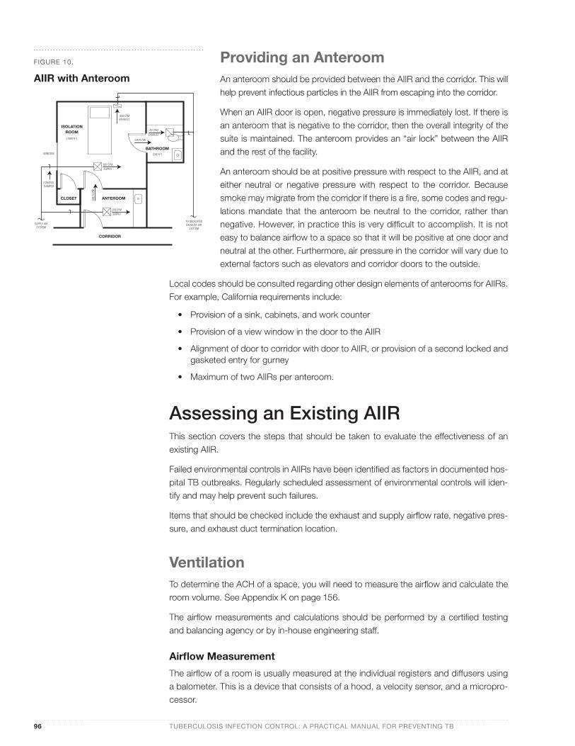
Providing an AnteroomAn anteroom should be provided between the AIIR and the corridor. This will help prevent infectious particles in the AIIR from escaping into the corridor.
When an AIIR door is open, negative pressure is immediately lost. If there is an anteroom that is negative to the corridor, then the overall integrity of the suite is maintained. The anteroom provides an “air lock” between the AIIR and the rest of the facility.
An anteroom should be at positive pressure with respect to the AIIR, and at either neutral or negative pressure with respect to the corridor. Because smoke may migrate from the corridor if there is a fi re, some codes and regu-lations mandate that the anteroom be neutral to the corridor, rather than negative. However, in practice this is very diffi cult to accomplish. It is not easy to balance airfl ow to a space so that it will be positive at one door and neutral at the other. Furthermore, air pressure in the corridor will vary due to external factors such as elevators and corridor doors to the outside.
Local codes should be consulted regarding other design elements of anterooms for AIIRs. For example, California requirements include:
• Provision of a sink, cabinets, and work counter
• Provision of a view window in the door to the AIIR
• Alignment of door to corridor with door to AIIR, or provision of a second locked and gasketed entry for gurney
• Maximum of two AIIRs per anteroom.
Assessing an Existing AIIRThis section covers the steps that should be taken to evaluate the effectiveness of an existing AIIR.
Failed environmental controls in AIIRs have been identifi ed as factors in documented hos-pital TB outbreaks. Regularly scheduled assessment of environmental controls will iden-tify and may help prevent such failures.
Items that should be checked include the exhaust and supply airfl ow rate, negative pres-sure, and exhaust duct termination location.
VentilationTo determine the ACH of a space, you will need to measure the airfl ow and calculate the room volume. See Appendix K on page 156.
The airfl ow measurements and calculations should be performed by a certifi ed testing and balancing agency or by in-house engineering staff.
Airfl ow Measurement
The airfl ow of a room is usually measured at the individual registers and diffusers using a balometer. This is a device that consists of a hood, a velocity sensor, and a micropro-cessor.
ISOLATIONROOM
CLOSET ANTEROOM
BATHROOM
CORRIDOR
(1000 ft 3)
WINDOW
CONTROLDAMPER
SUPPLY AIRSYSTEM
TO DEDICATEDEXHAUST AIR
SYSTEM
100 CFMSUPPLY
200 CFMSUPPLY
-50 CFMEXHAUST
-250 CFMEXHAUST
AIR FLOW
(240 ft 3)
AIR
FLOW
FIGURE 10.
AIIR with Anteroom
The hood is placed over a register or diffuser and should completely cover the air outlet. The top of the hood should have a foam gasket that establishes a good seal between the hood and the ceiling or wall around the outlet.
The hood directs all air entering or leaving the outlet past a velocity-sensing grid. The area of the grid is fi xed. Therefore, the microprocessor can calculate and display the quantity of air being exhausted or supplied by the air outlet. Balometers usually provide an airfl ow reading in cubic feet of air per minute (CFM).
The standard size of a balometer hood outlet is 24" X 24", although adapters are provided to adjust the hood size. This size hood can be used to measure the airfl ow of any outlet equal to or smaller than this (e.g., 12" X 24" or 18" X 18" diffuser). For other size outlets, such as a 36" X 6" slot diffuser, the hood size on the balometer may need to be changed.
There may not be suffi cient space in front of some outlets to place the balometer. In this case, the airfl ow should be measured by a pitot traverse in the duct that serves the outlet.
A pitot traverse is a specialized measurement that requires access above the ceiling. Air velocity is measured at a number of sample locations inside the duct. Airfl ow is calculated based on these velocity readings and the area of the duct cross-section. However, pitot traverses are not as accurate as balometers.
If a dedicated exhaust fan serves the AIIR suite, it may be possible to estimate the airfl ow at the room by measuring the airfl ow at this fan. Because of duct leakage, this measure-ment will not be as accurate as one taken at or near the outlet. Inadequately sealed duct joints can result in extra air being sucked into the duct between the AIIR exhaust grille and the fan, which would result in an overestimate of airfl ow in the room. To compensate for this, an allowance of at least 10% should be made. This allowance should be increased in the case of a long duct run.
If room airfl ow is found to be inadequate, i.e., less than 12 ACH, it should be increased. For information on modifying existing room airfl ow, see “Upgrading or Converting an Ex-isting Room” on page 101.
Air Mixing and Directional Airfl owAfter establishing the airfl ow, the next step is to evaluate how effectively this air is used in the AIIR. This assessment is not as straightforward as calculating the airfl ow rate because there is no clearly defi ned numerical standard to meet.
Smoke testing can be used to visualize the direction of room air and to estimate how well air is mixing. Consequently, ventilation problems can be identifi ed, such as undesirable directional airfl ow patterns and poor mixing.
Ideally, the clean supply air will be introduced near a HCW, while exhaust air will be re-moved near the patient. Good air mixing is confi rmed by rapid dissipation of the test smoke in all parts of the room, which demonstrates that particles generated in the room are being diluted and removed.
If air mixing is not optimal due to short-circuiting or stagnation, the diffuser and/or register should be relocated or replaced. Either of these options will require the services of a con-sultant mechanical engineer. In the interim, a supplemental propeller-type fan can be placed in the AIIR to encourage air mixing. Such a fan is not recommended as a long-term solution because it may create uncomfortable drafts and be turned off by the patient.
AIRBORNE INFECTION ISOLATION ROOMS 97
Regularly
scheduled
assessment of
environmental
controls will identify
and may help
prevent failures.
98 TUBERCULOSIS INFECTION CONTROL: A PRACTICAL MANUAL FOR PREVENTING TB
Exhaust Ductwork and DischargeThe engineering department staff at the facility should trace the path taken by the exhaust air duct after it leaves the AIIR. If applicable, they should also check the exhaust duct serving the bathroom and anteroom. For the record, a set of drawings should be gener-ated (or an existing design set marked) to show the ductwork and fan.
The exhaust ductwork and fan should also be checked for optimum performance. Condi-tions that should be corrected include: excess air leakage at duct joints, damaged duct-work, incorrectly adjusted dampers, and fans in need of servicing.
Recirculating Air Systems
If air from an AIIR is returned to a recirculating ventilation system that does not include HEPA fi ltration, this room should no longer be used for isolation. Staff and patients in rooms served by this system may be exposed to M. tuberculosis from patients in isolation.
The risk of exposure from a recirculating mechanical system is affected by dilution of the return air with outside air and by the fi lter in the mechanical system. The risk is reduced as the percentage of outside air is increased and the effi ciency of the fi lter is increased.
Filtration in hospital ventilation systems is usually better than in clinics because hospitals are typically covered by stricter building codes and have larger facilities and maintenance budgets.
Dedicated or Shared Exhaust System
The CDC Guidelines do not address the issue of dedicated exhaust air systems serving AIIRs. However, in some jurisdictions this is mandated by the building code for new or renovated rooms. Because most building codes are not retroactive, it is usually accept-able for an existing AIIR to combine the exhaust air with other exhaust systems, such as those serving bathrooms.
Duct and Fan Labeling
If the existing exhaust system is dedicated, make sure that the ductwork is labeled as recommended for a new AIIR (“Caution—AIIR Exhaust”). For a shared system, only the ductwork between the AIIR and the main exhaust trunk needs to be labeled.
The exhaust fan, whether dedicated or shared, should have a warning label as recom-mended for a new system (“AIIR Exhaust Fan—Contact Infection Control Coordinator Before Turning Off Fan”).
See “Handling AIIR Exhaust” on page 92, for additional information on labeling of exhaust ductwork and fans.
Verifying Negative PressureNegative pressure is the easiest characteristic of an AIIR to check. Several methods are available to qualitatively assess negative air pressure, including smoke tube testing and tissue testing.
If the AIIR is operating as intended, there will be an air current moving into the room under the door. The existence and direction of this current should be verifi ed.
Smoke Tube Test
Smoke tube testing helps visualize the current near a room door. In this simple procedure, smoke is released near the air gap under an AIIR door. See “Smoke Tube Testing Method for AIIRs” on page 106 for more detailed instructions.
Commercially available smoke-generating kits produce a visible cloud, which usually con-sists of water and acid. The quantity of smoke typically issued from the tube is minimal and is undetectable at short distances from the tube. Because inhalation of this smoke in concentrated form can cause irritation, care should be taken not to expose workers or patients until the smoke has been diluted. The amount of smoke used should not be ex-cessive.
There are many different types of easy-to-use smoke-generating kits available from safety supply companies. A typical design is the disposable self-contained puff bottle. Another common design is the disposable smoke tube, which attaches to a rubber bulb that acts like a bellows.
If commercial smoke-generating devices are not available, incense sticks can be used. CNTC recommends that two sticks be used side-by-side. However, incense smoke does have a strong odor, and is not as visible or controllable as commercial smoke.
Tissue Test
If smoke-generating devices are not available, or if the room is occupied by a patient who may be vulnerable to the irritant properties of smoke, a thin strip of tissue can be used to determine whether a room is at negative, neutral, or positive pressure. A thin strip of tissue should be held parallel to the gap be-tween the fl oor and bottom of the door. The direction of the tissue‘s movement will indicate the direction of air movement.
Manometer
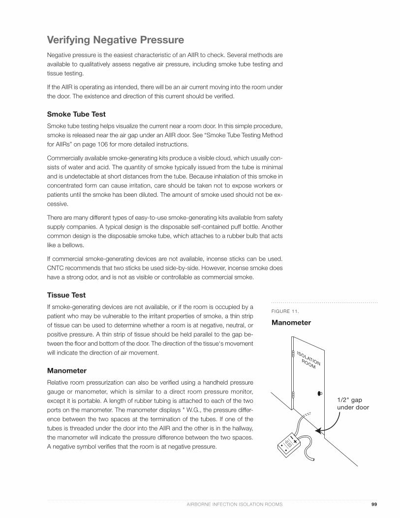
Relative room pressurization can also be verifi ed using a handheld pressure gauge or manometer, which is similar to a direct room pressure monitor, except it is portable. A length of rubber tubing is attached to each of the two ports on the manometer. The manometer displays " W.G., the pressure differ-ence between the two spaces at the termination of the tubes. If one of the tubes is threaded under the door into the AIIR and the other is in the hallway, the manometer will indicate the pressure difference between the two spaces. A negative symbol verifi es that the room is at negative pressure.
1/2" gapunder door
FIGURE 11.
Manometer
AIRBORNE INFECTION ISOLATION ROOMS 99

100 TUBERCULOSIS INFECTION CONTROL: A PRACTICAL MANUAL FOR PREVENTING TB
Velometer
Air speed is measured by a velometer, usually in units of feet per minute (FPM). These devices can be placed near the gap under the AIIR door to measure the speed of the airstream. Velometers are available in a number of different confi gurations. Many only in-dicate air speed regardless of air direction. For instance, some velometers indicate how fast the air is moving, but not whether the air is entering or leaving the room. However, there are models available that can also be used to determine airfl ow direction.
Repeat Test
All of these tests to verify negative pressure should be conducted at least three times until the results are consistent.
Validate Existing Monitor
If the existing room is equipped with a permanent room pressure monitor, one of the above tests should be performed to confi rm negative pressure and to validate the moni-tor. Also, the AIIR Pressure Monitor Checklist (Appendix C on page 145) should be com-pleted for the monitor.
Measuring Negative PressureAfter negative pressure has been verifi ed, it should be measured. Table 10 summarizes three ways to quantify negative pressure. The corresponding units of measurement and the measuring device for each method are also shown.
PARAMETER UNITS OF MEASUREMENT MEASURING DEVICE
pressure difference inches of water gauge ( " W.G.) manometer
speed of air under the door feet per minute (FPM) velometer
exhaust air offset cubic feet per minute (CFM) balometer
TABLE 10.
How to Quantify Negative Pressure
Upgrading or Converting an Existing RoomThis section covers methods of improving the ventilation characteristics of an existing room to make it more effective for AII.
Previous sections have outlined recommendations for a new state-of-the-art AIIR and have shown how to assess an existing room to see how it compares with these recommenda-tions. This section describes how to correct defi ciencies found during the assessment.
The methods outlined below could also be used to convert an existing patient room into an AIIR.
• Disconnect Recirculating Air System
The fi rst step is to ensure that air from the room is not inadequately fi ltered and re-circulated to other areas. The air removed from the room must either be exhausted outdoors to a safe location or HEPA-fi ltered. If room exhaust is currently connected to a recirculating air system that does not include a HEPA fi lter, it should be discon-nected from this system.
• Install HEPA Filter in Existing Return Air System
Theoretically, another safe option for correcting a recirculating system is to replace the existing fi lter with a HEPA fi lter. However, CNTC does not recommend this. A HEPA fi lter is a specialized piece of equipment that should only be used in a ventila-tion system specifi cally designed to accommodate it. HEPA fi lters are physically larger than most fi lters and require larger fans to overcome increased resistance to airfl ow.
• Two Upgrade/Conversion Options
There are two basic approaches to upgrading or creating an AIIR. The preferred op-tion is to adjust the building ventilation system to create a permanent AIIR. A tem-porary solution is to add a recirculating HEPA fi lter unit to supplement, or even re-place, the building ventilation system.
Regardless of the upgrade option selected, steps must be taken to reduce un-wanted air leakage from the room, i.e., the room must be sealed.
• Negative Pressure
As explained previously, the negative pressure value will depend on two factors: how much more air is exhausted than supplied (i.e., the offset); and how well the room is sealed. In general, when converting or upgrading a room, the negative pres-sure value will not be as high as that attainable for new construction because there is less control over the architectural elements.
CNTC recommends that the negative pressure value should be at least minus 0.006" W.G. for upgraded or converted AIIRs.
This is more stringent than the CDC Guidelines, which recommend ≥ 0.01" of water gauge as a minimum negative pressure value.
AIRBORNE INFECTION ISOLATION ROOMS 101
102 TUBERCULOSIS INFECTION CONTROL: A PRACTICAL MANUAL FOR PREVENTING TB
Sealing the RoomA room in which exhaust exceeds supply will not necessarily be at negative pressure with respect to the corridor; it is not unusual to have such a room at positive pressure.
For example, a room could have exhaust air from the central system exceeding supply by 100 CFM. Assume this room has leaky windows and some holes in the ceiling tiles. If it is windy outdoors, 75 CFM could enter through the leaks around the windows, and another 75 CFM could enter through the ceiling. Now the air being introduced to the room ex-ceeds exhaust by 50 CFM. Smoke testing at the door would probably indicate positive pressurization.
When upgrading an existing AIIR or converting an existing room to operate at negative pressure, it is important to make the best use of the excess exhaust by sealing the room as tightly as possible. For a given exhaust air offset, the better the room is sealed, the greater the amount of air that will fl ow into the room under the door and the greater the negative pressure.
The following are some examples of steps that can be taken to improve a room’s air-tightness:
• Apply gasketing at sides and top of room door
• Caulk around windowpanes and around window frames
• Apply gasketing at the connection of the ceiling and the walls
• Apply gasketing around electrical boxes
• Replace acoustic ceiling tiles with non-porous vinyl tiles and apply gasketing at tile connection to ceiling grid
• Replace recessed light fi xtures with surface-mounted fi xtures
Adjusting the Ventilation SystemIf the room is not currently connected to an exhaust system, it should be either connected to an existing exhaust system or a new system should be installed. Consult with the build-ing facilities department staff, which will probably hire a mechanical engineering consul-tant to design this work and oversee the construction.
Connect to Existing Exhaust System or Add New One
If there is an accessible exhaust air system nearby, such as a toilet exhaust system, with suffi cient capacity, it may be possible to make a new exhaust connection to the existing return register. Otherwise, a new exhaust air fan and ductwork system should be installed.
New exhaust ducts, and new or existing exhaust fans serving AIIRs, should have the same warning labels used for new AIIRs.
Rebalance Existing Mechanical System
To increase room airfl ow and/or create, or increase, negative pressure, the existing venti-lation system needs to be adjusted to exhaust more air. The supply air quantity may also need to be increased. Airfl ow is varied using dampers.
Adjust Dampers
Dampers are devices that control the fl ow of air in ducts, similar to the way valves control the fl ow of fl uids in pipes. Dampers, usually located above the ceiling, should only be adjusted by a facility engineer or certifi ed air balance contractor. To increase airfl ow, the dampers in the ducts serving the room should be opened wider. It usually takes an air balancer two or three adjustments to obtain the desired airfl ow.
The exhaust airfl ow rate should be at least 12 ACH. For existing rooms, this recommen-dation is more restrictive than the CDC Guidelines, which accept an air change rate of 6 ACH. However, 6 ACH will not satisfy some local regulatory agencies, including Cal/OSHA and the Offi ce of Statewide Health Planning and Development (OSHPD) in California. Twelve (12) ACH, which meets all local requirements known to CNTC, is readily achiev-able using HEPA fi lter units.
The supply should be approximately 100 CFM less than exhaust. Depending on how well the room is sealed, more air may need to be exhausted in order to achieve a larger pres-sure differential.
Most rooms do not have a dedicated ventilation system. They are connected to a fan system that serves other rooms in the building. Before and after adjusting the AIIR airfl ow, the air balancer should measure the airfl ow in some of these other spaces to make sure that the AIIR adjustments do not have an adverse effect on ventilation elsewhere.
Adding a Recirculating HEPA Filter UnitIt may not be possible or practical to connect to an existing exhaust air system, or to in-stall a new one. It is possible to create a temporary and less expensive AIIR. This can be done using a recirculating HEPA fi lter unit. There are two basic ways to use these units in AIIRs. They can be used to increase only the ventilation rate of a room without affecting room pressurization. Or they can be used to simultaneously:
• Increase the ventilation rate,
• Create or increase negative pressure, and
• Replace the need for additional exhaust.
HEPA Filter Units
HEPA fi lter units are readily available electrical devices that consist primarily of a fan, a HEPA fi lter, and a prefi lter. They also include controls, such as a three-speed switch, and possibly an indicator light to indicate when the fi lter needs to be changed.
HEPA fi lter units are available in a number of different physical confi gurations, including wall- and ceiling-mounted types. The most popular confi guration is the fl oor-standing, portable type.
Wall- or ceiling-mounted units are less obtrusive and do not take up fl oor space. They are also less likely to be tampered with by staff and patients. However, fl oor-mounted units are more portable and are easier to service. Regulatory bodies, such as OSHPD in Cali-fornia, may require that a structural engineer oversee the design and construction of the support system for a wall-mounted or ceiling-mounted HEPA fi lter unit.
AIRBORNE INFECTION ISOLATION ROOMS 103
104 TUBERCULOSIS INFECTION CONTROL: A PRACTICAL MANUAL FOR PREVENTING TB
Increase Ventilation Rate
If negative pressure in the AIIR is satisfactory, but the ventilation rate is low, a HEPA fi lter can be used to supplement the room airfl ow rate. The effective ventilation rate of the room is the sum of the central system airfl ow and the HEPA fi lter unit airfl ow.
Sizing HEPA Filter Units
The size of the unit selected should be based on the additional airfl ow (in CFM) required to achieve the desired ACH in your room. To determine the additional airfl ow:
• Measure the actual CFM exhausted from the room, and
• Calculate the CFM required to achieve the desired ACH. The HEPA fi lter unit should be sized to make up the difference.
Most HEPA fi lter units allow staff to adjust the amount of air delivered by means of a switch. Common examples of switches include those with three fi xed settings and those that allow any setting between the maximum and minimum. Manufacturers‘ catalogs generally list a CFM delivered by the unit at each of the three speeds, or at the high and low setting.
In practice, people usually turn down the HEPA fi lter unit switch and operate the units at or near the low setting. This is because the units can be very noisy and/or drafty when the fan is at, or near, full speed.
CNTC recommends that HEPA fi lter units be selected based on the airfl ow at or near the low speed.
These units may deliver less than the manufacturers‘ listed airfl ow, and output of the units may decrease as the fi lters load up. To compensate for this, it is recommended that the unit selected have a listed capacity that is 25% more than required. The marginal cost of selecting a unit with more capacity is usually not signifi cant, compared to the initial cost of the unit.
To summarize, it is recommended that a unit is selected that can deliver 25% more CFM than required at or near the low speed fan setting.
For example, if 150 CFM is measured, and 220 CFM is required to achieve 12 ACH, then the required additional airfl ow is 70 CFM. If a HEPA fi lter unit is used to increase airfl ow, then 25% should be added to 70 CFM for a total of approximately 90 CFM. Therefore, a unit with a listed capacity of at least 90 CFM at or near the low fan speed setting should be selected.
Increase Ventilation Rate and Create or Increase Negative Pressure
If a suffi cient portion of the discharge from a HEPA fi lter unit is ducted somewhere outside of the room, then the HEPA fi lter unit can create negative pressure and replace the need for any extra exhaust.
A HEPA fi lter unit supplements ventilation as follows:
• The effective exhaust air quantity is increased by an amount equal to the airfl ow of the HEPA fi lter unit (because this air is now being removed and droplet nuclei are removed by the fi lter)
• The effective supply is increased by an amount equal to the returned air quantity (HEPA unit airfl ow minus the amount discharged outside the room)
• The effective negative pressure offset is increased by an amount equal to the HEPA unit airfl ow discharged outside the room.
Theoretically, the technique described above could also be used to create negative pres-sure in a room that had no ventilation system. However, this is not recommended be-cause the room would then have no outside air at all, only recirculated, HEPA-fi ltered air. Building codes mandate that fresh outdoor air be supplied to all occupied spaces that do not have an operable window.
Monitoring the Environmental ControlsOnce the AIIR upgrade has been completed, procedures to monitor the environmental controls must be implemented. This is essential to ensure that staff will be alerted if the controls fail.
The two items that need to be monitored are the airfl ow rates and the room pressurization.
Airfl ow Rate Monitoring
The airfl ow rates are monitored by measuring with a balometer to ensure that the rates have not deviated more than about 5% from the initial values.
Airfl ow rates should be measured and air change rates calculated at least once a year.
Room Pressurization Monitoring
Room pressurization should be continuously monitored to ensure that the room remains under negative pressure.
The CDC Guidelines recommend that room pressurization be confi rmed daily while the room is occupied by a suspected or known infectious TB patient, and at least once a month at other times.
These tests can be done with smoke or a telltale device, such as a tissue. However, it is recommended that each AIIR be equipped with a permanent room pressure monitor.
Documentation
Records should be kept of all AIIR environmental control tests and measurements. Local regulatory agencies may require that these records be kept for a number of years. For example, Cal/OSHA requires that records be kept for a minimum of fi ve years.
AIRBORNE INFECTION ISOLATION ROOMS 105
106 TUBERCULOSIS INFECTION CONTROL: A PRACTICAL MANUAL FOR PREVENTING TB
Smoke Trail (or Smoke Tube) Testing Method for Negative Pressure AIIRsSmoke from a smoke tube can be used to observe airfl ow between areas or airfl ow pat-terns within an area. Smoke tube testing must be performed outside the room with the door closed.
To check the negative pressure in a room, hold the smoke tube near the bottom of the door and approximately 2 inches in front of the door, or at the face of a grille or other door opening. Generate a small amount of smoke by gently squeezing the bulb.
The smoke tube should be held parallel to the door, and the smoke should be issued slowly from the tube to ensure that the velocity of the smoke does not overpower the air velocity. The smoke will travel in the direction of airfl ow.
If the room is at negative pressure, the smoke will travel under the door and into the room (e.g., from higher to lower pressure). If the room is not at negative pressure, the smoke will be blown outward or will remain stationary.
If there is an anteroom, release smoke at the inner door undercut, with both anteroom doors shut.
In addition to a pedestrian entry, some AIIRs or areas are accessed through a wider wheeled-bed stretcher door. Release smoke at all door entrances to AIIRs or areas.
If room air cleaners are being used in the room, they should be running during the test.
Because the smoke is irritating if inhaled, care should be taken to prevent direct inhalation from the smoke tube. However, the quantity of smoke issued from the tube is minimal and is not detectable at short distances from the tube.

Background The setting is an AIIR with a dedicated bathroom. Supply air to the AIIR is 200 CFM.
The Options The AIIR volume is approximately 1,000 cubic feet, so the supply air change rate is 12 ACH.
You are installing a new exhaust fan with a capacity of 300 CFM that will serve only the AIIR suite. Local codes mandate a minimum of 10 ACH in bathrooms. The bathroom volume is approximately 240 cubic feet, so a minimum of 40 CFM exhaust is required.
How should the 300 CFM of exhaust air be split up between the bathroom and the AIIR?
Should 250 CFM be exhausted in the AIIR and 50 CFM in the bathroom?
Or should 200 CFM be exhausted in the AIIR and the remaining 100 CFM in the bathroom?
The Best OptionThe preferred arrangement is to exhaust 250 CFM at the AIIR and 50 CFM at the bathroom (as shown in the above diagram), rather than 200 CFM at the AIIR and 100 CFM at the bathroom.
The Reason Each arrangement will result in both a 100 CFM off-set across the AIIR door and an equal volume of air moving through the AIIR. But only the preferred op-tion provides more exhaust than supply in the AIIR itself, resulting in negative pressure, and increases airfl ow towards the head of the bed.
Also, code offi cials may require that direct exhaust from the AIIR exceed direct supply air. The latter op-tion would result in a room with supply equal to ex-haust.
ISOLATIONROOM
CLOSET ANTEROOM
BATHROOM
CORRIDOR
(1000 ft 3)
WINDOW
CONTROLDAMPER
SUPPLY AIRSYSTEM
TO DEDICATEDEXHAUST AIR
SYSTEM
100 CFMSUPPLY
200 CFMSUPPLY
-50 CFMEXHAUST
-250 CFMEXHAUST
AIR FLOW
(240 ft 3)
AIR
FLOW
Dedicated Bathroom
AIRBORNE INFECTION ISOLATION ROOMS 107
CA
SE
ST
UD
Y
108 TUBERCULOSIS INFECTION CONTROL: A PRACTICAL MANUAL FOR PREVENTING TB
CA
SE
ST
UD
Y
WINDOW
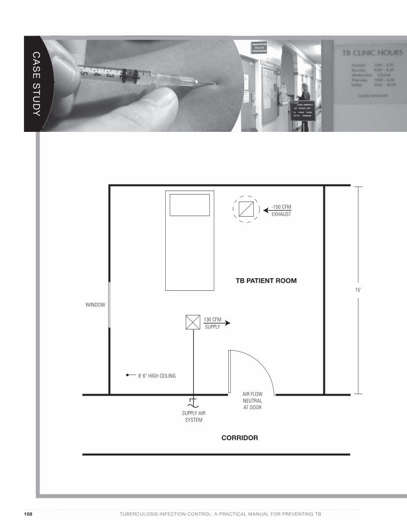
-150 CFMEXHAUST
TB PATIENT ROOM
130 CFMSUPPLY
8' 6" HIGH CEILING
15'
SUPPLY AIRSYSTEM
AIR FLOWNEUTRALAT DOOR
CORRIDOR
What steps should be taken to achieve negative pressure in the AIIR?
AIRBORNE INFECTION ISOLATION ROOMS 109
AIIR: Part One
Background Routine annual tuberculin skin testing revealed that two employees in a small, single-story county clinic converted their TSTs over the last year. Both employees were clerks in the billing department; neither had patient contact.
Assessment The clinic manager, Janet, was concerned because the billing department shares a corridor with the room used to isolate TB patients. M. tuberculosis transmission may have occurred due to failed envi-ronmental controls in the AIIR.
Janet tested pressurization of the AIIR with a piece of tissue. The room clearly had positive pressure with respect to the corridor. She felt airfl ow from the supply grille. Even after wiping off the consider-able amount of dust on the exhaust grille, there was no air movement. A tissue held against the grille was not pulled toward the grille as would be expected.
The county facilities department sent out a maintenance engineer, Cynthia, to investigate further.
Cynthia remembered converting this room into an AIIR for TB patients about 2 years ago. She had sealed the room and installed a small, dedicated rooftop exhaust fan. But now she found that dust and lint had accumulated on the fan motor, causing the motor to overheat and burn out. She cleaned the fan and ductwork and replaced the motor. Exhaust was now measured and found to be 150 CFM.
Room air supply was 130 CFM, which was 20 CFM less than exhaust. However, a series of smoke tests showed that the room was now at neutral pressure rather than negative pressure. Room air leakage exceeded the 20 CFM offset.
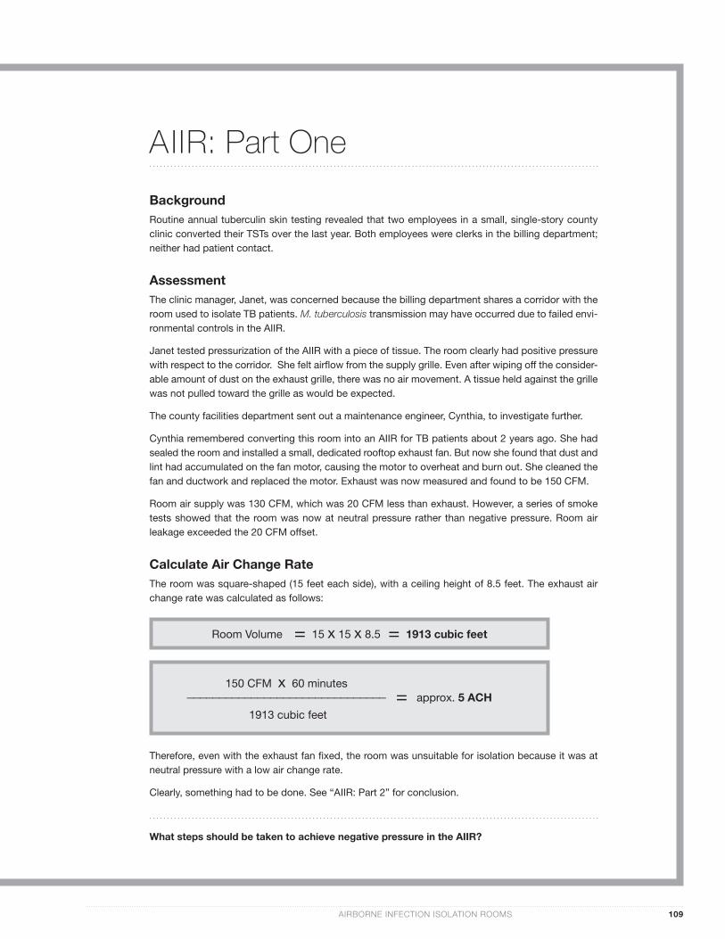
Calculate Air Change Rate The room was square-shaped (15 feet each side), with a ceiling height of 8.5 feet. The exhaust air change rate was calculated as follows:
Therefore, even with the exhaust fan fi xed, the room was unsuitable for isolation because it was at neutral pressure with a low air change rate.
Clearly, something had to be done. See “AIIR: Part 2” for conclusion.
Room Volume = 15 x 15 x 8.5 = 1913 cubic feet
150 CFM x 60 minutes_______________________________
1913 cubic feet
= approx. 5 ACH
110 TUBERCULOSIS INFECTION CONTROL: A PRACTICAL MANUAL FOR PREVENTING TB
CA
SE
ST
UD
Y
AIIR: Part Two
Calculate Additional Airfl ow Although Janet, the clinic manager, wanted to bring the AIIR into compliance with CDC environmen-tal control recommendations, she thought her budget was too limited to accomplish this.
Cynthia, the engineer, suggested a portable HEPA fi lter unit as an affordable upgrade option. A HEPA fi lter unit would provide additional airfl ow. If a portion of the discharge were ducted outside, it would also create negative pressure.
The fi rst step was to calculate the additional airfl ow required:
Sizing and Installing a Portable HEPA Filter UnitA HEPA fi lter unit that produced at least 250 CFM airfl ow was required. Cynthia contacted a me-chanical equipment supplier. Two units were available: a small unit rated for 150 to 300 CFM; and a large unit rated for 250 to 750 CFM. Each unit had a variable speed switch and an optional connec-tion that could be used to duct some of the discharge air outdoors.
Janet suggested buying the small unit to save money. If run at high speed, it would provide more than enough airfl ow. However, Cynthia explained that most people turn down the fan speed switch be-cause the units can be noisy. The units may also produce less airfl ow than the catalog claims. She suggested adding a 25% safety factor, then buying a unit listed for this airfl ow at low or medium speed.
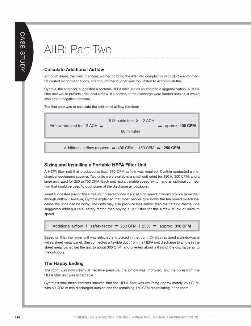
Based on this, the larger unit was selected and placed in the room. Cynthia replaced a windowpane with a sheet metal panel. She connected a fl exible duct from the HEPA unit discharge to a hole in the sheet metal panel, set the unit to about 300 CFM, and diverted about a third of the discharge air to the outdoors.
The Happy Ending The room was now clearly at negative pressure, the airfl ow was improved, and the noise from the HEPA fi lter unit was acceptable.
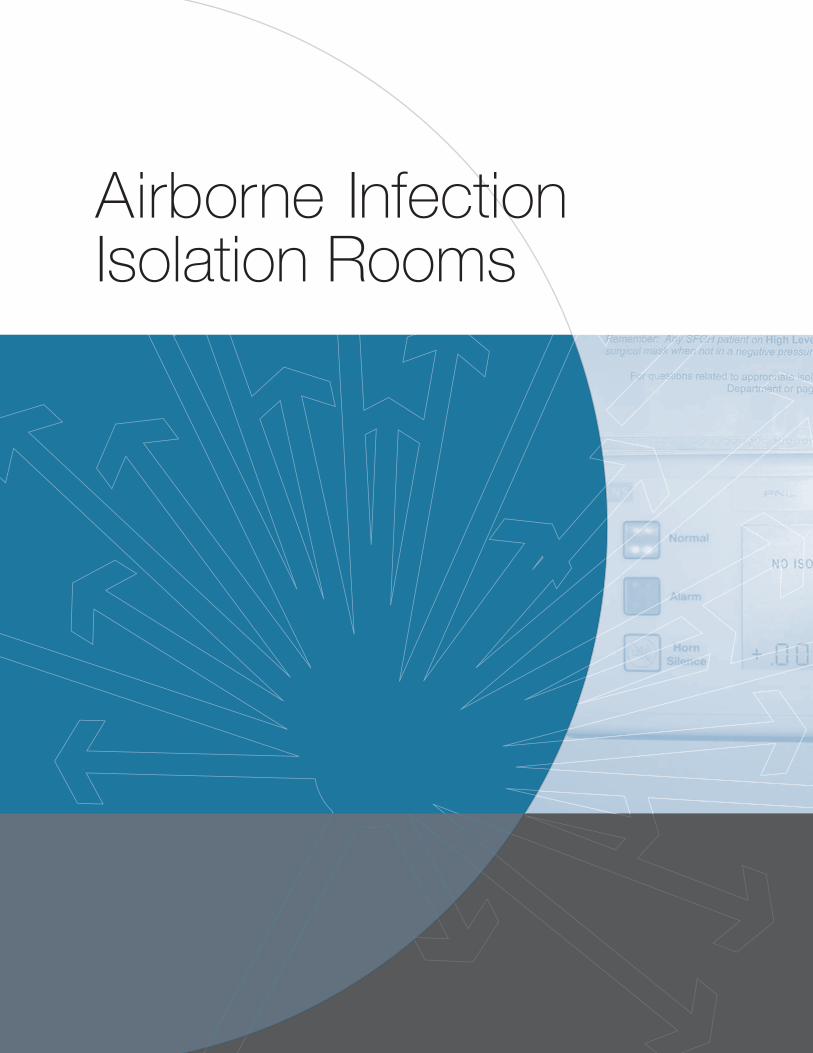
Cynthia‘s fi nal measurements showed that the HEPA fi lter was returning approximately 250 CFM, with 80 CFM of this discharged outside and the remaining 170 CFM recirculating in the room.
Additional airfl ow required = 400 CFM - 150 CFM = 250 CFM
Airfl ow required for 12 ACH = = approx. 400 CFM1913 cubic feet x 12 ACH______________________
60 minutes
Additional airfl ow + safety factor = 250 CFM + 25% = approx. 310 CFM
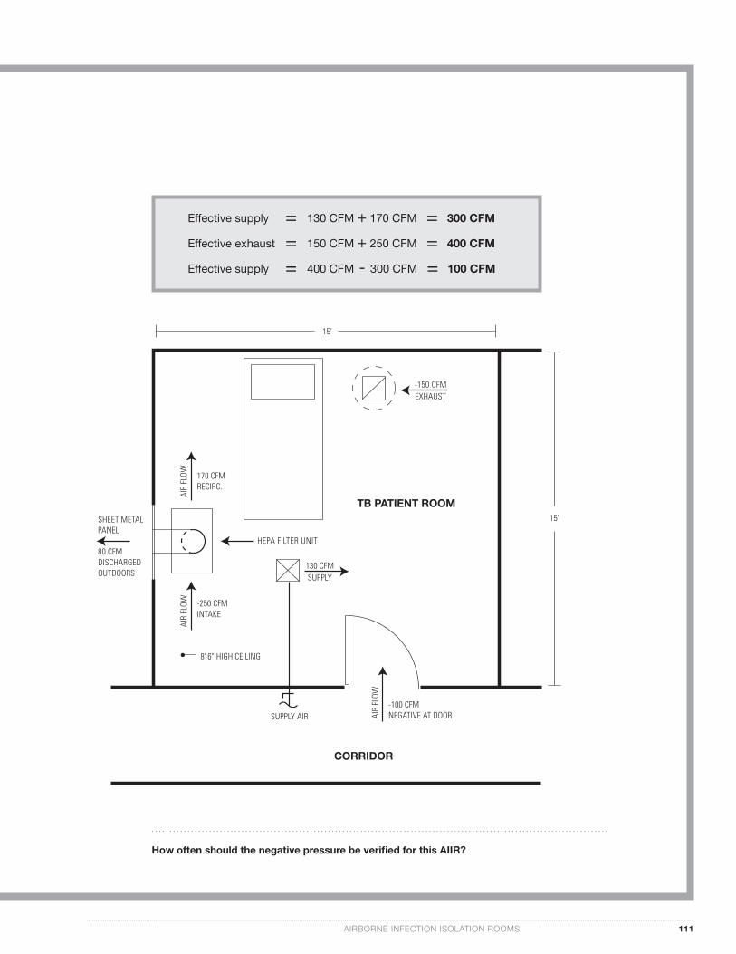
-150 CFMEXHAUST
TB PATIENT ROOM
130 CFMSUPPLY
HEPA FILTER UNIT
8' 6" HIGH CEILING
15'
SUPPLY AIR-100 CFMNEGATIVE AT DOOR
SHEET METALPANEL
80 CFMDISCHARGEDOUTDOORS
AIR
FLOW
CORRIDOR
15'
170 CFMRECIRC.
AIR
FLOW
-250 CFMINTAKE
AIR
FLOW
Effective supply = 130 CFM + 170 CFM = 300 CFM Effective exhaust = 150 CFM + 250 CFM = 400 CFM
Effective supply = 400 CFM - 300 CFM = 100 CFM
AIRBORNE INFECTION ISOLATION ROOMS 111
How often should the negative pressure be verifi ed for this AIIR?