Bentley OpenRoads Workshop 2017 FLUG Fall Training Event · 2018-02-01 · Mastering the Corridor...
61
Bentley OpenRoads Workshop 2017 FLUG Fall Training Event T-1E - Mastering the Corridor Bentley Systems, Incorporated 685 Stockton Drive Exton, PA 19341 www.bentley.com
Transcript of Bentley OpenRoads Workshop 2017 FLUG Fall Training Event · 2018-02-01 · Mastering the Corridor...

Bentley OpenRoads Workshop
2017 FLUG Fall Training Event
T-1E - Mastering the Corridor
Bentley Systems, Incorporated 685 Stockton Drive Exton, PA 19341 www.bentley.com
Practice WorkbookThis workbook is designed for use in Live instructor-led training and for OnDemand self study. OnDemand videos for this course are available on the Bentley LEARN Server.
DO NOT DISTRIBUTE - Printing for student use is permitted
TRNC02408-1/0002
Mastering the Corridor
SELECTseries 4 (08.11.09.872)About this Practice Workbook...
This PDF file includes bookmarks providing an overview of the document. Click on the bookmark to quickly jump to any section in the file. You may have to turn on the bookmark function in your PDF viewer.
Both Imperial and Metric files are included in the dataset. Throughout this practice workbook Imperial values are specified first and the metric values second with the metric values enclosed in square brackets. For example: 12’ [3.4m]
This training uses the Bentley-Civil workspace delivered with the software. It is very important that you select the Bentley-Civil workspace when working the exercises in this course.
Have a Question? Need Help?
If you have questions while taking this course, click the button below to submit them to the Civil Design Forum on Bentley Communities where peers and Bentley subject matter experts are available to help.
Copyright © 2016 Bentley Systems, Incorporated 2DO NOT DISTRIBUTE - Printing for student use is permitted
Exercise 1: Creating and Evaluating a Corridor
DescriptionA Corridor, in the simplest terms, applies a typical section along a 3D backbone to produce a 3D model.
In this exercise, we will create a corridor and review its properties.
Skills Taught Create a Corridor
Review its Properties to make corrections
Getting Started
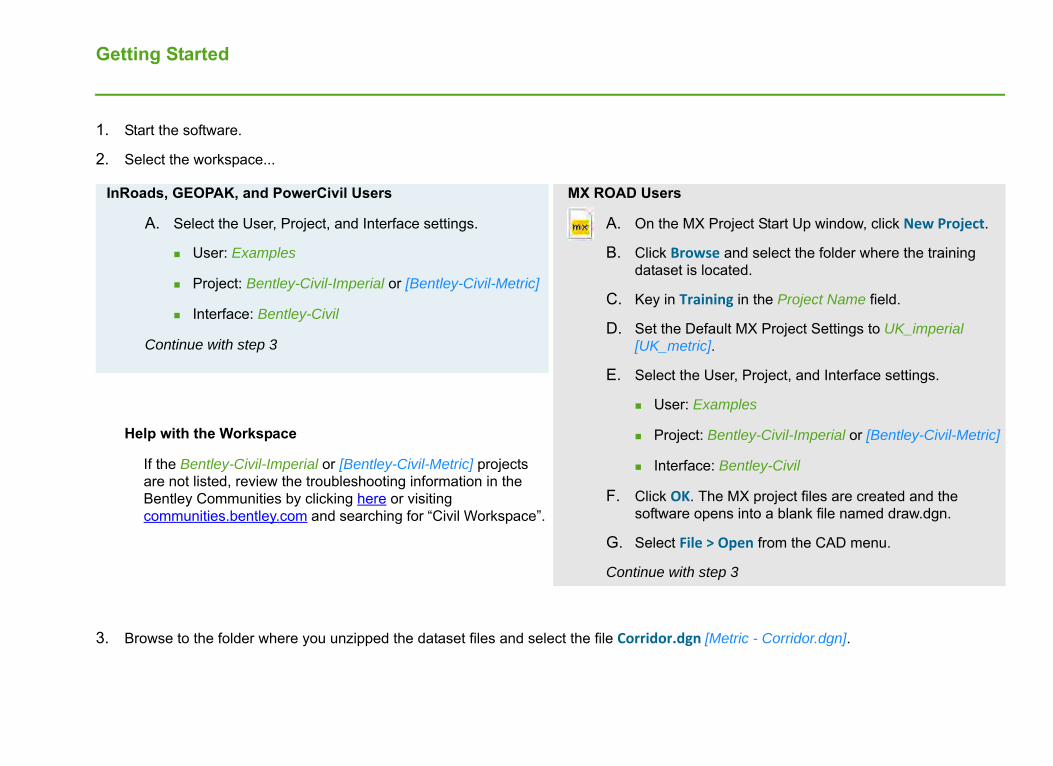
1. Start the software.
2. Select the workspace...
Help with the Workspace
If the Bentley-Civil-Imperial or [Bentley-Civil-Metric] projects are not listed, review the troubleshooting information in the Bentley Communities by clicking here or visiting communities.bentley.com and searching for “Civil Workspace”.
3. Browse to the folder where you unzipped the dataset files and select the file Corridor.dgn [Metric - Corridor.dgn].
InRoads, GEOPAK, and PowerCivil Users
A. Select the User, Project, and Interface settings.
User: Examples
Project: Bentley-Civil-Imperial or [Bentley-Civil-Metric]
Interface: Bentley-Civil
Continue with step 3
MX ROAD Users
A. On the MX Project Start Up window, click New Project.
B. Click Browse and select the folder where the training dataset is located.
C. Key in Training in the Project Name field.
D. Set the Default MX Project Settings to UK_imperial [UK_metric].
E. Select the User, Project, and Interface settings.
User: Examples
Project: Bentley-Civil-Imperial or [Bentley-Civil-Metric]
Interface: Bentley-Civil
F. Click OK. The MX project files are created and thesoftware opens into a blank file named draw.dgn.
G. Select File > Open from the CAD menu.
Continue with step 3
Copyright © 2016 Bentley Systems, Incorporated 4DO NOT DISTRIBUTE - Printing for student use is permitted
Review the Data
Before we start building things, let’s examine our starting conditions.
1. Make sure Element Information is visible. We will use it frequently.
2. What is in the Active File and what is in References?
a. Turn off the Display of all the References.
b. Review the elements in the active design file.
Observe that the active design file is empty.
c. Undo to return to the original reference file display settings.
WARNING: It is recommended you use Undo as suggested. If you choose to manually turn off and on the reference display be aware that the display is OFF for the Default-3D models in the Wall SB1 - Component.dgn and Geometry.dgn references.
3. Note what’s in the reference files:
Geometry.dgn: mainline horizontal and vertical geometry.
Site-Grading.dgn: elements that define localized design elements along the corridor such as alternate edges of pavement, driveways, graded pads, and boundary around an environmentally sensitive area.
Terrain - Existing.dgn: the existing terrain model.
Wall SB1 - Component.dgn: elements that define a proposed wall.

Copyright © 2016 Bentley Systems, Incorporated 5DO NOT DISTRIBUTE - Printing for student use is permitted
Create a Corridor
1. Click on and hover over the centerline. Select the Create Corridor tool.
a. In the Tool Settings dialog, set the Design Stage to 0 ‐ Functional
Following the heads up prompts:
b. Locate Profile - Reset For Active Profile: Click Reset (right) mouse button
c. Corridor Name: Type Alden Parkway and click Data (left) mouse button to accept.
d. Template: Hold down the ALT key and press the down arrow key to open the Pick Template dialog.
e. Browse to and select the Templates > Urban > 2 Lane Urban Curb and Gutter with Sidewalk template.
f. Click OK.
g. Click Data mouse button to accept template
h. Start Station: Press the Alt key to Lock to Beginning at the southern end of the alignment, then click Data mouse button to accept.
i. End Station: Press ALT key to lock to the End of the Alignment, then click Data mouse button to accept.
j. Interval: Type 20 [10] and click Data mouse button to accept.
NOTE: this interval should be no longer than the interval of the final cross sections that will be created for the project.
k. Minimum Transition Before Drop: Type 0 and click Data mouse button to accept.
l. Minimum Transition After Drop: Type 0 and click Data mouse button to accept.
m.Type 2 Lane for Description and click Data mouse button to accept and process the corridor.
Copyright © 2016 Bentley Systems, Incorporated 6DO NOT DISTRIBUTE - Printing for student use is permitted
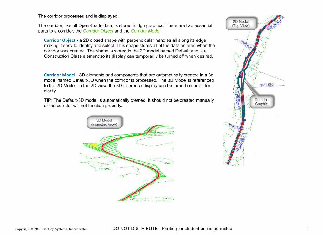
The corridor processes and is displayed.
The corridor, like all OpenRoads data, is stored in dgn graphics. There are two essential parts to a corridor, the Corridor Object and the Corridor Model.
Corridor Object - a 2D closed shape with perpendicular handles all along its edge making it easy to identify and select. This shape stores all of the data entered when the corridor was created. The shape is stored in the 2D model named Default and is a Construction Class element so its display can temporarily be turned off when desired.
Corridor Model - 3D elements and components that are automatically created in a 3d model named Default-3D when the corridor is processed. The 3D Model is referenced to the 2D Model. In the 2D view, the 3D reference display can be turned on or off for clarity.
TIP: The Default-3D model is automatically created. It should not be created manually or the corridor will not function properly.

Copyright © 2016 Bentley Systems, Incorporated 7DO NOT DISTRIBUTE - Printing for student use is permitted
Review the Corridor Information
1. Select the Corridor object.
It is the 2D perimeter of the corridor. The graphic can be selected anywhere, but it has handles for easy selection.
2. Review the Corridor’s properties in the Element Information dialog.
As is typical in OpenRoads, the settings that we input during creating can easily be reviewed and edited if something needs correction.
The top panel of the Element Information dialog shows the expandable “data tree” of the corridor. Clicking on the Corridor Object, in this case Alden Parkway, shows the Name of the Corridor, the Profile used, and the Design Stage (that information is listed in the Corridor group at the bottom).
Expanding the Templates header and clicking on the Template Drop, we see the information we input about the Template, including the Template used, the Drop Interval, and the Start and Stop Stations.
3. Correct any errors before continuing.
Copyright © 2016 Bentley Systems, Incorporated 8DO NOT DISTRIBUTE - Printing for student use is permitted
Exercise 2: Working with a Corridor
DescriptionViewing the corridor seems, at face value, to be a straightforward activity. Because it’s the core of the civil engineering deliverable, however, people have a wide variety of uses and needs for the corridor. The many settings deliver wide flexibility and a wide range of results.
In this section we will explore the settings in Design Stages and how they affect the 2D, 3D and Cross Section Models.
Skills Taught View the Corridor in Cross Section view
Review and change Corridor Design Stages
Copyright © 2016 Bentley Systems, Incorporated 9DO NOT DISTRIBUTE - Printing for student use is permitted
Understanding the 2D and 3D Models
Geometry Horizontal geometry is defined in the 2D model. Vertical geometry is also defined through the 2D model with the use of a Profile view.
However, once a geometry element has an active vertical profile, a 3D version of the element is automatically created in the 3D model.
The 3D model is automatically referenced to the 2D model and it behaves like any other referenced model, its Display may be on or off. Sometimes you will want the 3D model display on, other times you may want to turn off the 3D display for clarity.
Corridor The Corridor Object is created in the 2D model.
The result of the corridor is created in the 3D model. The 3D model can be displayed as components, linear features, a top surface, or a bottom surface mesh.
In addition some 2D geometry elements may also be displayed as part of the corridor depending on how Feature Definitions are setup in your workspace. The 2D elements are created when
the Feature Definition’s Create Template Geometry parameter is set to True, AND
when the Design Stage (discussed later in the exercise) Create Linear Feature setting is ON.
For now, it is important to know that the 2D view may be showing 2D features collinear with 3D features referenced from the 3D model. This is very powerful but can be distracting at times.
However, you always have control over what you see in the 2D view. You control that view by turning reference displays on and off and by controlling how the 3D model appears. How the 3D model appears is controlled by something called a Design Stage which we will get to later in this exercise.

Copyright © 2016 Bentley Systems, Incorporated 10DO NOT DISTRIBUTE - Printing for student use is permitted
Review the Corridor in the Cross Section View
A very useful review tool is the Cross Section View (not to be confused with the Cross Section sheeting functionality).
1. Select and hover over the Corridor and select the Open Cross Section Model tool.
The Select or Open View prompt is asking you to place a data point in an open view or to Open a View and click in it to define where the cross sections are displayed.
We will view the cross sections in View 5. There is nothing special about View 5, you can use any of the eight views.
a. If View 5 is not open, open it by clicking on the 5 button in the View Group at the bottom of the screen.
b. Once View 5 is open, click inside the view and the Cross Section is displayed.

Copyright © 2016 Bentley Systems, Incorporated 11DO NOT DISTRIBUTE - Printing for student use is permitted
2. The vertical exaggeration of the cross section can be adjusted to make it easier to view.
a. Select the down arrow next to View Properties in the view’s left corner.
b. Type an appropriate number such as 5 in the Vertical Exaggeration field.
3. Click the left and right arrow icons to scroll through the cross sections. The arrows move to the next or previous template drop. Note the Station number display.
4. To skip to a specific station, select the down arrow next to the station value and type in a specific station if you desire.
NOTE: The view is showing dynamic cross sections extracted from the 3D Model. All elements in the 3D model will appear in the cross section and a cross section can be cut at any station.
The Location Station via DataPoint tool is used to select a cross section station from the plan view. This tool can be selected from the Task menu or from a pop-up menu accessed by right clicking in the cross section view.
5. Select Locate Station via Datapoint.
a. At the Locate Corridor or Alignment prompt, select the corridor.
A dashed line appears showing where the cross section will be cut.
b. Place a data point where you want to see a section.
HINT: Snap to an existing element to view a cross section at a specific location.
c. At the Select Cross Section View prompt, place a data point in View 5 (the view where the cross section will be displayed).
The section at the datapoint is displayed.
The cross sections at the design interval are still available so you can scroll fore and aft as needed.

Copyright © 2016 Bentley Systems, Incorporated 12DO NOT DISTRIBUTE - Printing for student use is permitted
What is a Corridor Design Stage?
Corridor Design Stages are preset bundles of settings that control how corridors appear in the 3D model. The also control the level of detail included in the 3D model. For preliminary work a Design Stage that creates a less detailed 3D model is very useful to speed up processing. While later in a project a Design Stage for final work is used to produce the most accurate 3D model necessary for construction.
If a corridor looks sparse, “blocky” or chorded, it is because the Design Stage is set to an early Design Stage such as the “Functional” stage included in the Bentley Civil Workspace. The Functional Design Stage’s primary advantage is speed but that comes at the sacrifice of details.
There are four categories of parameters in a Design Stage.
Template Management
One of the parameters of a Design State is the Template Drop Interval Multiplier. The Template Drop Interval is the interval specified when the corridor is created that defines the distance between template drops -- the interval at which cross sectional geometry along the corridor is modeled.
The Template Drop Interval Multiplier property increases the template drop interval resulting an a less dense model. For example, the Functional design stage has a multiplier of 10. So instead of our model being processed every 20’ [5m] as we specified, it is modeled every 200’ [50m]. This can be very useful to speed up processing when working on preliminary design scenarios.
Include Critical Sections
Another way Design Stages can speed up processing is by omitting cross sections at Critical Sections such as horizontal curve cardinal points.
Display Settings
The display settings define how the corridor object appears including its color, weight, etc. and the size of the handles that surround it. There are also settings for the appearance of the Template Drop and Transition object graphics that appear in the 2D view.

Copyright © 2016 Bentley Systems, Incorporated 13DO NOT DISTRIBUTE - Printing for student use is permitted
Output Settings
The Output Setting parameters define the type of 3D elements that are created in the 3D model. Options include a mesh along the top or bottom of the design surface, linear 3D features, or full 3D components. The Bottom Mesh is particularly useful for machine grading.
Copyright © 2016 Bentley Systems, Incorporated 14DO NOT DISTRIBUTE - Printing for student use is permitted
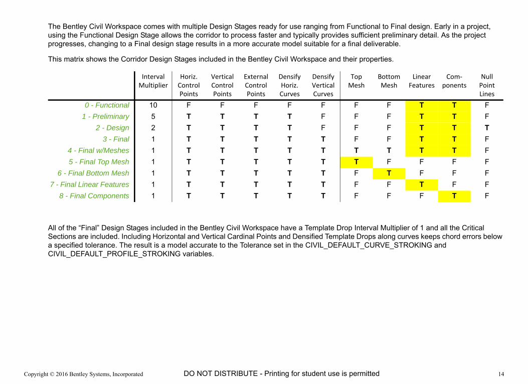
The Bentley Civil Workspace comes with multiple Design Stages ready for use ranging from Functional to Final design. Early in a project, using the Functional Design Stage allows the corridor to process faster and typically provides sufficient preliminary detail. As the project progresses, changing to a Final design stage results in a more accurate model suitable for a final deliverable.
This matrix shows the Corridor Design Stages included in the Bentley Civil Workspace and their properties.
All of the “Final” Design Stages included in the Bentley Civil Workspace have a Template Drop Interval Multiplier of 1 and all the Critical Sections are included. Including Horizontal and Vertical Cardinal Points and Densified Template Drops along curves keeps chord errors below a specified tolerance. The result is a model accurate to the Tolerance set in the CIVIL_DEFAULT_CURVE_STROKING and CIVIL_DEFAULT_PROFILE_STROKING variables.
Interval Multiplier
Horiz. Control Points
Vertical Control Points
External Control Points
Densify Horiz. Curves
Densify Vertical Curves
Top Mesh
Bottom Mesh
Linear Features
Com‐ponents
Null Point Lines
0 - Functional 10 F F F F F F F T T F1 - Preliminary 5 T T T T F F F T T F
2 - Design 2 T T T T F F F T T T3 - Final 1 T T T T T F F T T F
4 - Final w/Meshes 1 T T T T T T T T T F5 - Final Top Mesh 1 T T T T T T F F F F
6 - Final Bottom Mesh 1 T T T T T F T F F F7 - Final Linear Features 1 T T T T T F F T F F
8 - Final Components 1 T T T T T F F F T F

Copyright © 2016 Bentley Systems, Incorporated 15DO NOT DISTRIBUTE - Printing for student use is permitted
Corridor Design Stages
1. The 2D Model, the 3D Model, and the Cross Section Model views should all be visible as we review the Corridor Design Stages.
2. For clarity turn Off the 3D Model reference Display in the 2D View.
It is identified by the same File Name as the Active file (highlighted in yellow) and the Default-3D Model (highlighted in red).
3. Select the corridor and in the Element Information dialog, set the Design Stage to 8 ‐ Final Components.
In addition to the Template Drop Interval Multiplier changing to 1, this Design Stage is models all critical stations such as horizontal and vertical PCs and PTs.
The corridor displays the components that make up the 3D model.
4. Review the Cross Section Model. Notice that the interval now matches the new tighter interval of 20’ [10m].

Copyright © 2016 Bentley Systems, Incorporated 16DO NOT DISTRIBUTE - Printing for student use is permitted
5. Set the Design Stage to 7 ‐ Final Linear Features.
The corridor updates displaying only linear features which are created as a 3D line string connecting like named points in the template.
6. Review the Cross Section Model.
Since the cross sections are a “live slice through the 3D Model” the view now only shows points where the cross section intersects the linear features.
7. Set the Corridor’s Design Stage to 5 ‐ Final Top Mesh and then 6 ‐ Final Bottom Mesh and review the differences.
TIP: It might be helpful to rotate the 3D Model view to better view the meshes.
8. Before moving to the next section, set the Corridor Design Stage to the 3 ‐ Final.
This Design Stage creates both Linear Features and Component Meshes. In addition, the Bentley Civil Workspace is setup to automatically create 2D geometry for some template features. Those 2D elements are displayed in the 2D model. ‘
The remainder of the course uses the 3 - Final Design Stage but feel free to change the Design Stage, as well as turning the 3D Model On and Off, at your discretion.
Copyright © 2016 Bentley Systems, Incorporated 17DO NOT DISTRIBUTE - Printing for student use is permitted
Exercise 3: Defining Template Transitions
DescriptionOur corridor currently extrudes a single cross-sectional geometry along its entire length. Only the slope treatments outside the sidewalks vary geometrically to “find” the ground, which will be in varying depths of cut or fill.
Often the “backbone” of the corridor cross section needs to vary. There are several ways to do so which we will explore in this course.
The first method is to use different templates in different areas of the corridor. Perhaps the corridor changes from a 2 lane to a 4 lane cross section. Or some sections of the corridor include curb, gutter, and sidewalk and other sections include only a sidewalk. Or part of the corridor includes concrete pavement while other parts are asphalt pavement.
The transition between different templates need to be controlled to create an accurate 3D model. The software will automatically transition from one template to the next in a corridor as best it can by connecting like named template points. However, templates will be different and not all points will automatically transition or transition as required for the project. In this exercise you will learn how to control these transitions so they fully conform to your needs.
Skills Taught Add a second Template to the Corridor
Precisely define the transition between the two templates
Copyright © 2016 Bentley Systems, Incorporated 18DO NOT DISTRIBUTE - Printing for student use is permitted
Define a New Template Drop
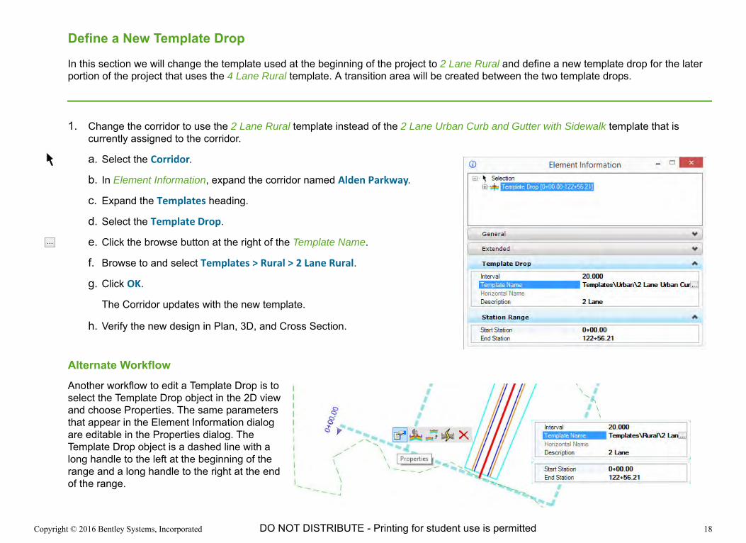
In this section we will change the template used at the beginning of the project to 2 Lane Rural and define a new template drop for the later portion of the project that uses the 4 Lane Rural template. A transition area will be created between the two template drops.
1. Change the corridor to use the 2 Lane Rural template instead of the 2 Lane Urban Curb and Gutter with Sidewalk template that is currently assigned to the corridor.
a. Select the Corridor.
b. In Element Information, expand the corridor named Alden Parkway.
c. Expand the Templates heading.
d. Select the Template Drop.
e. Click the browse button at the right of the Template Name.
f. Browse to and select Templates > Rural > 2 Lane Rural.
g. Click OK.
The Corridor updates with the new template.
h. Verify the new design in Plan, 3D, and Cross Section.
Alternate WorkflowAnother workflow to edit a Template Drop is to select the Template Drop object in the 2D view and choose Properties. The same parameters that appear in the Element Information dialog are editable in the Properties dialog. The Template Drop object is a dashed line with a long handle to the left at the beginning of the range and a long handle to the right at the end of the range.

Copyright © 2016 Bentley Systems, Incorporated 19DO NOT DISTRIBUTE - Printing for student use is permitted
2. Define a new Template Drop in the corridor for the 4 Lane Rural template.
a. Select Create Template Drop.
b. Select the corridor.
Following the heads up prompts:
c. Template: Hold down the ALT key and press the down arrow key to open the Pick Template dialog.
d. Browse to and select the Templates > Rural > 4 Lane Rural template.
e. Click OK.
f. Click Data mouse button to accept template
g. Start Station: Type 3100 [945], then click Data mouse button to accept.
h. End Station: Press ALT key to lock to the End of the Alignment, then click Data mouse button to accept.
i. Interval: Type 20 [3] and click Data mouse button to accept.
j. Minimum Transition Before Drop: Type 200 [60] and click Data mouse button to accept.
This defines the length of the template transition section prior the Start Station.
The 4-lane template will begin at station 31+00 [0+945] with a 200’ [60m] transition beginning at 29+00 [0+885].
The software will automatically change the previous template drop to end at station 29+00 [0+885] and add the transition section.
k. Minimum Transition After Drop: Type 0 and click Data mouse button to accept.
l. Description: 4 Lane.
A second template drop for the 4 Lane template is added to the corridor along with a 200 ft [60m] template transition.

Copyright © 2016 Bentley Systems, Incorporated 20DO NOT DISTRIBUTE - Printing for student use is permitted
Edit the Template Transition
In this section we will edit the template transition between the 2 Lane Rural and 4 Lane Rural templates.
1. Zoom the 2D view to the area of the transition.
The Transition “handles”, as shown to the right are very much like the Temple Drop graphic handles. They are longer and extend to the left at the beginning (lower station) and to the right at the ending (higher station). This makes it possible to select Template Drop and Transition graphics easily where they are at the same station. This quickly becomes very intuitive.
A close examination of the template transition shows that the automated process did a reasonable job but that the lane lines (the striping) are not drawn. The 2 lane template did not include a Lane point so there was nothing for the 4 lane template to match. When we are done editing the transition, the lane transitions will be visible.
2. Select the Transition graphic.
3. Select Edit Transition to begin editing the transition.
The Edit Transition dialog opens.
Its initial state shows a 3D isometric view of the two templates and the feature lines connecting them. The software automatically connects the template points that have matching names. Templates with inconsistent naming conventions will transition less automatically.
The template points shown by light or thin + symbols are connected successfully by the software.
The template points shown by heavy or bold + symbols are unresolved. The lane points (circled in red) in the 4 Lane template are unresolved.

Copyright © 2016 Bentley Systems, Incorporated 21DO NOT DISTRIBUTE - Printing for student use is permitted
4. Right‐click on any point on the 2 Lane template and select Move Template to move the template.
a. Position the template so you can clearly see the points in the 4 Lane template and the pavement edges in the 2 Lane template where they need to connect.
Either template can be moved to get the best view of the 2 Lane’s pavement edges and centerline and the unresolved lane points on the 4 Lane template.
b. Data point to stop moving the template.
NOTE: Each lane has four unresolved template points arranged vertically. However, the three lower ones are constrained upwards to the surface lane point. Therefore the two surface lane points at the top are the only points we need to define for the lane transitions.
5. Click on the Left Lane point on the 4 Lane template and connect it to the Left Edge of Pavement on the 2 Lane template.

Copyright © 2016 Bentley Systems, Incorporated 22DO NOT DISTRIBUTE - Printing for student use is permitted
NOTE: If you make a mistake, any transition line can be deleted by right-clicking on it and clicking Delete. Undo can also be used.
6. Repeat the process Right Lane point on the 4 Lane template and connect it to the Centerline on the 2 Lane template.
In this example the added lane tapers out from the centerline. If you prefer to transition in a different way (e.g., you want the lane to be continuous along the centerline and add lane on the outside), feel free to deviate after we run through the process once.
7. Click OK.
A reminder appears because the template geometry is rigidly fixed by its points’ constraint definitions. You will need to tell the Transition how to let it move the points.
8. Click OK to close the reminder dialog.
The Edit Transition Midpoint dialog appears.
This dialog is used to delete point constraints so that the template can transition properly.
The dialog is also used to test the template transition using the slider at the lower left corner of the dialog. The left side represents the transition at the first template; the right side the second template.
9. Slide the slider to the left and right sides. Note that the lanes do not transition. We will fix that.
Copyright © 2016 Bentley Systems, Incorporated 23DO NOT DISTRIBUTE - Printing for student use is permitted
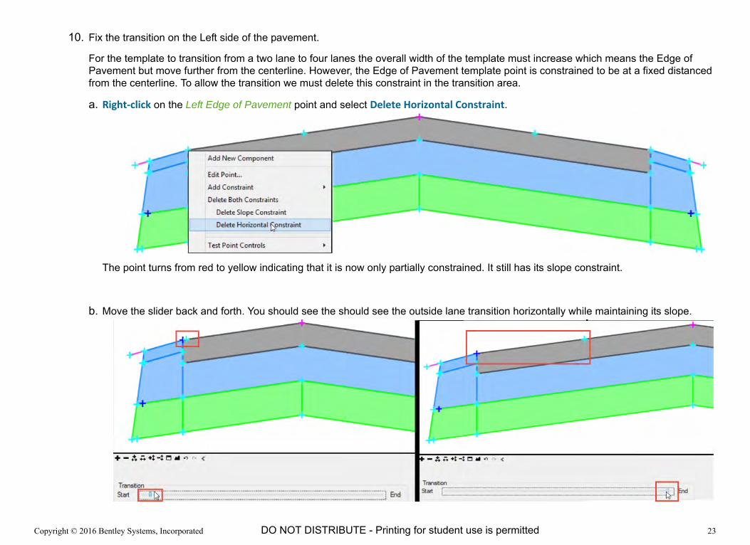
10. Fix the transition on the Left side of the pavement.
For the template to transition from a two lane to four lanes the overall width of the template must increase which means the Edge of Pavement but move further from the centerline. However, the Edge of Pavement template point is constrained to be at a fixed distanced from the centerline. To allow the transition we must delete this constraint in the transition area.
a. Right‐click on the Left Edge of Pavement point and select Delete Horizontal Constraint.
The point turns from red to yellow indicating that it is now only partially constrained. It still has its slope constraint.
b. Move the slider back and forth. You should see the should see the outside lane transition horizontally while maintaining its slope.

Copyright © 2016 Bentley Systems, Incorporated 24DO NOT DISTRIBUTE - Printing for student use is permitted
11. Fix the transition on the Right side of the pavement.
a. Right‐click on the Right Lane point and select Delete Horizontal Constraint.
b. Move the slider back and forth. You should see the width of the inner lane transition.
Note: if you transition the lanes differently, you will need to adjust the constraints correspondingly.
12. Click OK to save the edited transition.
NOTE: the image show the corridor’s Design Stage set to Final - Linear Features so the lane lines (linear features) are visible.
The transition in this example was created automatically by the Template Drop tool. However, transitions also be created manually using the Create Transition tool.
HINT: A quick way to review the transition in 2D and 3D is to use the 2D/ 3D View Control tool built into the Bentley Civil Workspace which opens a 3D isometric view of the area shown in the 2D view. Right-click and hold in a clear area in a view and select View Control > View 2D/3D.
Copyright © 2016 Bentley Systems, Incorporated 25DO NOT DISTRIBUTE - Printing for student use is permitted
Exercise 4: Controlling Corridor Geometry with Graphics
DescriptionTemplates represent cross sectional geometry as represented in “typical” section requirements. Few corridors have “typical” geometry along their entire length. How are deviations handled? If the deviations follow 2D or 3D graphics, Template Point Controls allow these graphics to override the positions of points as defined in the template, horizontally, vertically or both.
Skills Taught Assign an individual graphic to control a Pavement Edge
Override template geometry “en masse”
Edit Point Controls using Element Information
Copyright © 2016 Bentley Systems, Incorporated 26DO NOT DISTRIBUTE - Printing for student use is permitted
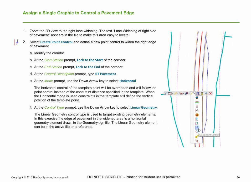
Assign a Single Graphic to Control a Pavement Edge
1. Zoom the 2D view to the right lane widening. The text “Lane Widening of right side of pavement” appears in the file to make this area easy to locate.
2. Select Create Point Control and define a new point control to widen the right edge of pavement.
a. Identify the corridor.
b. At the Start Station prompt, Lock to the Start of the corridor.
c. At the End Station prompt, Lock to the End of the corridor.
d. At the Control Description prompt, type RT Pavement.
e. At the Mode prompt, use the Down Arrow key to select Horizontal.
The horizontal control of the template point will be overridden and will follow the point control instead of the constraint distance specified in the template. When the Horizontal mode is used constraints in the template still define the vertical position of the template point.
f. At the Control Type prompt, use the Down Arrow key to select Linear Geometry.
The Linear Geometry control type is used to target existing geometry elements. In this exercise the edge of pavement in the widened area is a horizontal geometry element drawn in the Geometry.dgn file. The Linear Geometry element can be in the active file or a reference.

Copyright © 2016 Bentley Systems, Incorporated 27DO NOT DISTRIBUTE - Printing for student use is permitted
g. At the Point prompt, use the Arrow keys to select RT_EOP.
TIP: It may be easier to select the name from the Point pick list in the Tool Settings dialog.- OR- The point name can be graphically selected snapping to the point in the Cross Section view if it is open.
h. At the Locate Plan or Profile Element prompt, select the widened blue line that defines the widened Edge of Pavement.
i. At the Use as Secondary Alignment prompt, select No.
j. At the Priority prompt, type 1.
k. For the Start and Stop Offsets, type 0.
When complete, the Edge of Pavement is widened to follow the graphic.
Copyright © 2016 Bentley Systems, Incorporated 28DO NOT DISTRIBUTE - Printing for student use is permitted
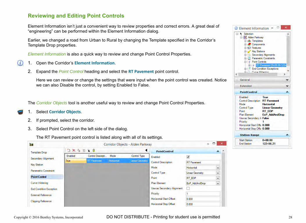
Reviewing and Editing Point Controls
Element Information isn’t just a convenient way to review properties and correct errors. A great deal of “engineering” can be performed within the Element Information dialog.
Earlier, we changed a road from Urban to Rural by changing the Template specified in the Corridor’s Template Drop properties.
Element Information is also a quick way to review and change Point Control Properties.
1. Open the Corridor’s Element Information.
2. Expand the Point Control heading and select the RT Pavement point control.
Here we can review or change the settings that were input when the point control was created. Notice we can also Disable the control, by setting Enabled to False.
The Corridor Objects tool is another useful way to review and change Point Control Properties.
1. Select Corridor Objects.
2. If prompted, select the corridor.
3. Select Point Control on the left side of the dialog.
The RT Pavement point control is listed along with all of its settings.

Copyright © 2016 Bentley Systems, Incorporated 29DO NOT DISTRIBUTE - Printing for student use is permitted
Secondary Alignments
One of the settings for a Point Control is to use the control as a Secondary Alignment, but what does that actually do? Secondary Alignments change the “perpendicularity” of the cross sectional geometry. Normally, cross-sectional geometry is defined as perpendicular to the baseline. When cross-sectional geometry crosses a Secondary Alignment it changes its direction to be perpendicular to the Secondary Alignment.
An example of using an Edge of Pavement as a Secondary Alignment would be if the side slope is graded perpendicular to an Add Lane Taper rather than perpendicular to the centerline.
The image to the right shows the right side extra lane with Use Secondary Alignments toggled False and True, respectively.
Curb Returns at intersections are another example of where Secondary Alignments are often used.
1. Use either Element Information or the Corridor Object to change the RT Pavement Point Control’s Use as Secondary Alignment setting to True.
Observe the results.
Copyright © 2016 Bentley Systems, Incorporated 30DO NOT DISTRIBUTE - Printing for student use is permitted
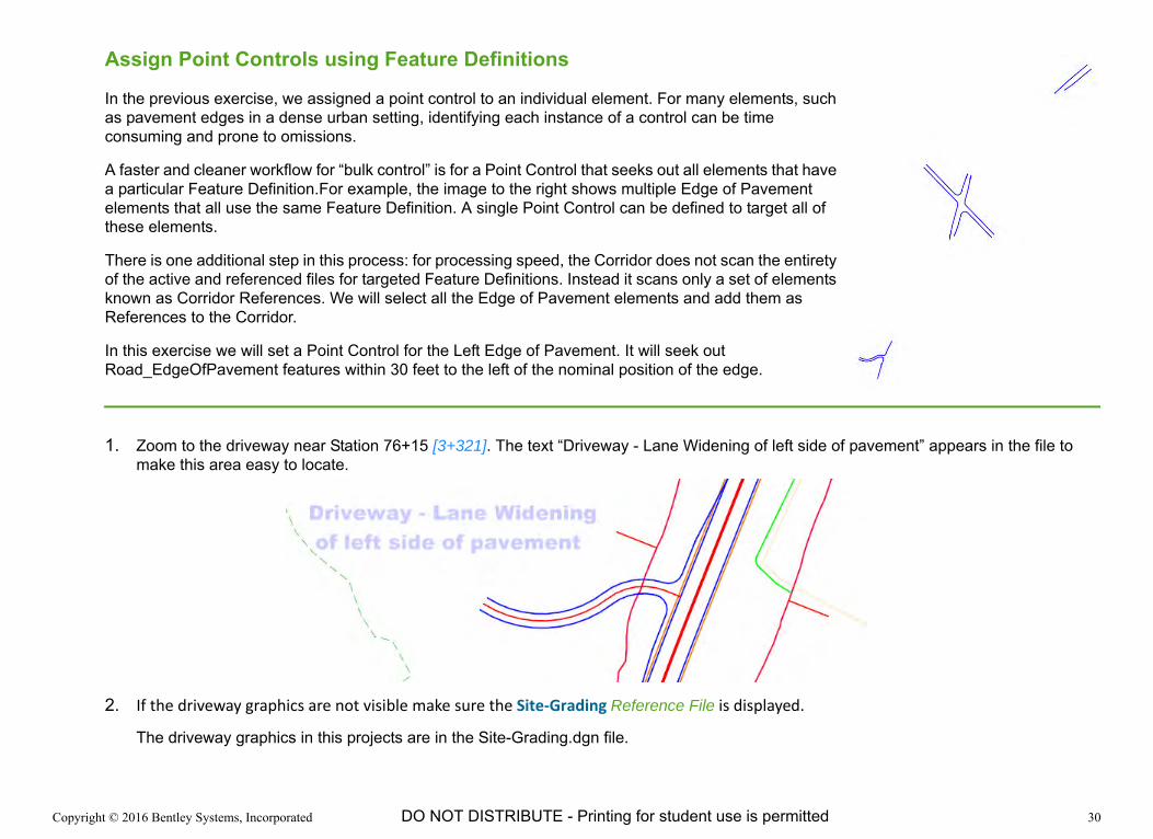
Assign Point Controls using Feature Definitions
In the previous exercise, we assigned a point control to an individual element. For many elements, such as pavement edges in a dense urban setting, identifying each instance of a control can be time consuming and prone to omissions.
A faster and cleaner workflow for “bulk control” is for a Point Control that seeks out all elements that have a particular Feature Definition.For example, the image to the right shows multiple Edge of Pavement elements that all use the same Feature Definition. A single Point Control can be defined to target all of these elements.
There is one additional step in this process: for processing speed, the Corridor does not scan the entirety of the active and referenced files for targeted Feature Definitions. Instead it scans only a set of elements known as Corridor References. We will select all the Edge of Pavement elements and add them as References to the Corridor.
In this exercise we will set a Point Control for the Left Edge of Pavement. It will seek out Road_EdgeOfPavement features within 30 feet to the left of the nominal position of the edge.
1. Zoom to the driveway near Station 76+15 [3+321]. The text “Driveway - Lane Widening of left side of pavement” appears in the file to make this area easy to locate.
2. If the driveway graphics are not visible make sure the Site‐Grading Reference File is displayed.
The driveway graphics in this projects are in the Site-Grading.dgn file.
Copyright © 2016 Bentley Systems, Incorporated 31DO NOT DISTRIBUTE - Printing for student use is permitted
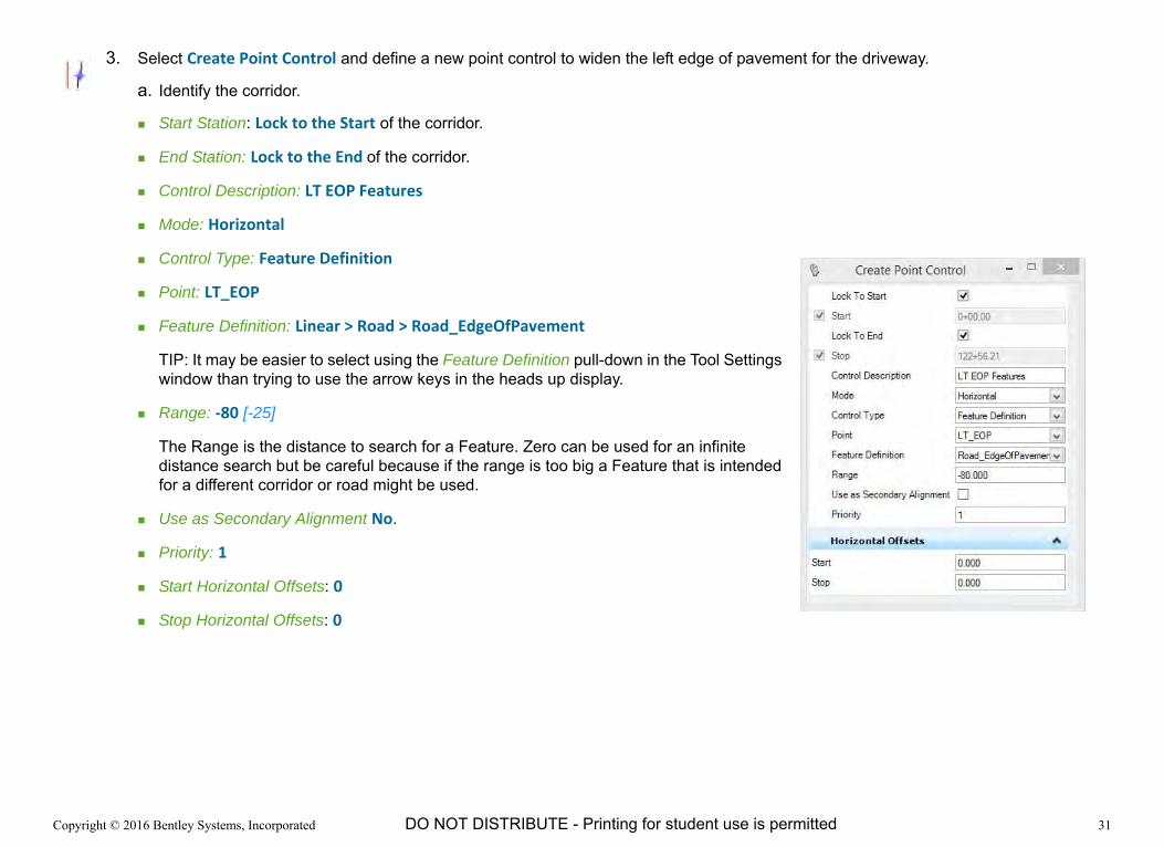
3. Select Create Point Control and define a new point control to widen the left edge of pavement for the driveway.
a. Identify the corridor.
Start Station: Lock to the Start of the corridor.
End Station: Lock to the End of the corridor.
Control Description: LT EOP Features
Mode: Horizontal
Control Type: Feature Definition
Point: LT_EOP
Feature Definition: Linear > Road > Road_EdgeOfPavement
TIP: It may be easier to select using the Feature Definition pull-down in the Tool Settings window than trying to use the arrow keys in the heads up display.
Range: ‐80 [-25]
The Range is the distance to search for a Feature. Zero can be used for an infinite distance search but be careful because if the range is too big a Feature that is intended for a different corridor or road might be used.
Use as Secondary Alignment No.
Priority: 1
Start Horizontal Offsets: 0
Stop Horizontal Offsets: 0

Copyright © 2016 Bentley Systems, Incorporated 32DO NOT DISTRIBUTE - Printing for student use is permitted
The Corridor processes, but no change is seen. The Features have to be added to the corridor as References enabling the corridor to search them for a matching Feature Definitions and thus included them in the Point Control.
4. Select the Edges of Pavement graphics that will be referenced to the corridor.
a. Select the Element Selection tool.
b. Expand the Extended Settings.
c. Select the Levels tab.
d. Select the Road_EdgeOfPavement level.
All of the elements on the level are highlighted (indicating their selection) and the level is moved to the top of the list.
5. Add the Elements as Corridor References.
a. With the elements still selected, select Add Corridor Reference from the Tasks (not from the Context menu).
The Task menu must be used because selecting the corridor to use the Context menu will clear the selection of the elements in the previous step.
b. At the Locate Corridor prompt, select the corridor.
c. You will be prompted to confirm with a datapoint to Apply the selection elements as References. Confirm with a data point.
The Corridor processes and the left pavement edges are now coincide with any Edges of Pavement at the driveway.
6. Review the corridor at the driveway.
NOTE: if your left edges did not adjust properly, we will show how to troubleshoot in the next section.
Copyright © 2016 Bentley Systems, Incorporated 33DO NOT DISTRIBUTE - Printing for student use is permitted
Introducing the Corridor Objects Dialog
In order for the pavement edges to adjust in bulk two distinct things have to happen: the Point Control must be defined correctly and the References must be available to the Corridor.
We have shown how to review and change the Point Controls via Element Information. As valuable a tool as it is, it exposes only a subset of the Corridor’s properties and dependents.
The Corridor Objects is a dialog with broad reach and massive powers. Its icon is a Bucket. Consider it a Giant Bucket of Powers.
Hyperbole aside, its capabilities overlap and exceed those of Element Information.
Verifying that the Pavement Edges are Corridor References cannot be done with Element Information, but can with Corridor Objects.
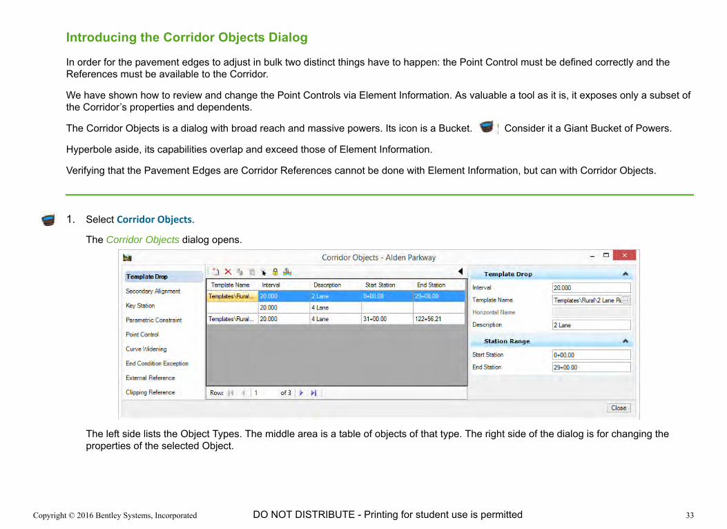
1. Select Corridor Objects.
The Corridor Objects dialog opens.
The left side lists the Object Types. The middle area is a table of objects of that type. The right side of the dialog is for changing the properties of the selected Object.
Copyright © 2016 Bentley Systems, Incorporated 34DO NOT DISTRIBUTE - Printing for student use is permitted
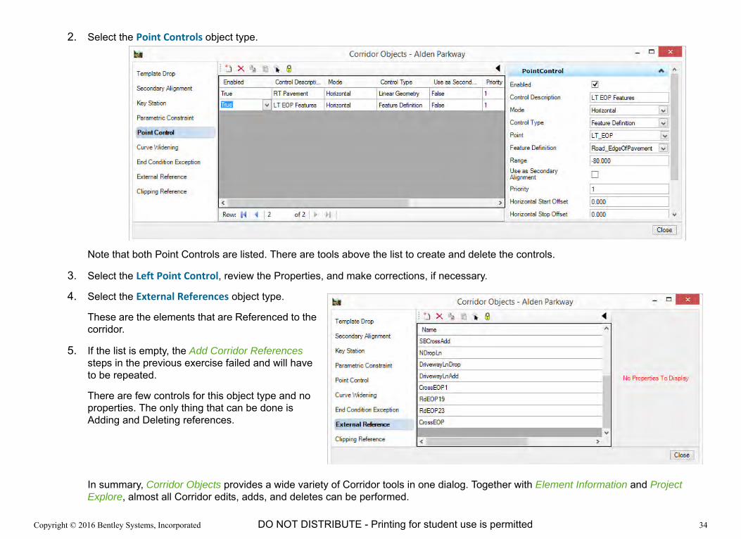
2. Select the Point Controls object type.
Note that both Point Controls are listed. There are tools above the list to create and delete the controls.
3. Select the Left Point Control, review the Properties, and make corrections, if necessary.
4. Select the External References object type.
These are the elements that are Referenced to the corridor.
5. If the list is empty, the Add Corridor References steps in the previous exercise failed and will have to be repeated.
There are few controls for this object type and no properties. The only thing that can be done is Adding and Deleting references.
In summary, Corridor Objects provides a wide variety of Corridor tools in one dialog. Together with Element Information and Project Explore, almost all Corridor edits, adds, and deletes can be performed.

Copyright © 2016 Bentley Systems, Incorporated 35DO NOT DISTRIBUTE - Printing for student use is permitted
Exercise 5: Targeting Something Other than the Existing Terrain
DescriptionJust because, most of the time, our corridors tie in to the existing ground, it is not the only thing Corridors can “target.” We can tie in to other corridors (ramps, crossing streets), driveways, pads, proposed surfaces, walls, etc.
In this exercise we will tie in to some of these other targets.
Skills Taught Tie in along a horizontal line
Target a Wall
Intercept a Proposed Clearing

Copyright © 2016 Bentley Systems, Incorporated 36DO NOT DISTRIBUTE - Printing for student use is permitted
Tying in to a Horizontal Line
Sometimes we have already established where we want a side slope to meet the existing terrain. A number of Bentley Civil Workspace Templates including 2 Lane Rural, 4 Lane Rural, 2 Lane Urban, and 5 Lane Urban are setup to tie directly to the existing terrain at a horizontal line. If a line with a Feature Definition of Grade_Fixed_Tie is found, these templates will automatically tie to it. The Feature must be included as a Corridor Reference.
This fixed tie functionality is also defined in the End Conditions > Fixed Tie folder of the workspace template library so it can easily be added to other templates.
Below we will add some Corridor References to elements defined with the Grade_Fixed_Tie Feature Definition to fix the side slope tie down around an Environmentally Sensitive Area.
1. Zoom to the Environmentally Sensitive Area (ESA) located to the east of the driveway.

Copyright © 2016 Bentley Systems, Incorporated 37DO NOT DISTRIBUTE - Printing for student use is permitted
2. Add a corridor reference for the green line on the east side of the sensitive area.
The green line has already been defined to use the Fixed_Grade_Tie Feature Definition. The side slopes from the road will tie to this line and avoid the sensitive area due to the capabilities already built into the templates we are using for this project and that are delivered with the Bentley Civil Workspace.
a. Select Add Corridor Reference.
b. If prompted, select the Corridor.
c. At the Locate First Reference prompt, click on the green Fixed_Grade_Tie line to the left of the ESA.
d. Reset to complete selection.
The Corridor processes and the side slope daylights to the left of the ESA.
Notice that we can see this result in the 2D view because the boundary graphic for the corridor is not coincident with the sensitive area tie down graphic.

Copyright © 2016 Bentley Systems, Incorporated 38DO NOT DISTRIBUTE - Printing for student use is permitted
Targeting a Wall
By convention, most Templates aim for the existing ground. It’s a good default. However, there are plenty of times when something else needs to be the target, such as a proposed pad, yard, another road, a wall, etc. Sometimes there is a whole list of things that you might want to target, with the existing ground being the “last resort”.
The technology in the software to define a sequence of targets is called Target Aliasing. When an End Condition targets the Active Surface, Target Aliasing lists the various targets that will be attempted and the order they will be targeted. Once the End Condition successfully reaches a target it is successful and build, subsequent targets in the list are not attempted.
For example, the dialog shows that when the Template is targeting the Active Surface, it will first look for the Wall SB1 corridor, then the SouthPad terrain model, and so on. If it finds none of the targets at the top of the list, it will seek the last item on the list, the Existing Terrain.
1. Zoom the 2D view to the wall which is located to the south of the driveway.

Copyright © 2016 Bentley Systems, Incorporated 39DO NOT DISTRIBUTE - Printing for student use is permitted
2. Right-click and hold in a clear area in the 2D view and select View Control > View 2D/3D.
Remember for earlier that this tool that matches the 3D view to the current 2D view is included in the Bentley Civil Workspace.
3. Zoom and rotate the 3D view so that the existing wall is clear.
Observe that the corridor side slope are not tied to the wall. They extend through the wall and tie to the existing ground as if the wall did not exist. The corridor currently does not know about the wall, so it ignores it.
4. Use Target Aliasing to tell the Corridor to look first for the wall and then, if it does not find it, to seek the Existing Terrain.
a. Select Define Target Aliasing.
b. If prompted, select the corridor.
The Target Aliasing dialog opens.
The Controls in the middle are used to populate and sequence the Alias list on the right from available surfaces and corridors listed on the left.
Copyright © 2016 Bentley Systems, Incorporated 40DO NOT DISTRIBUTE - Printing for student use is permitted
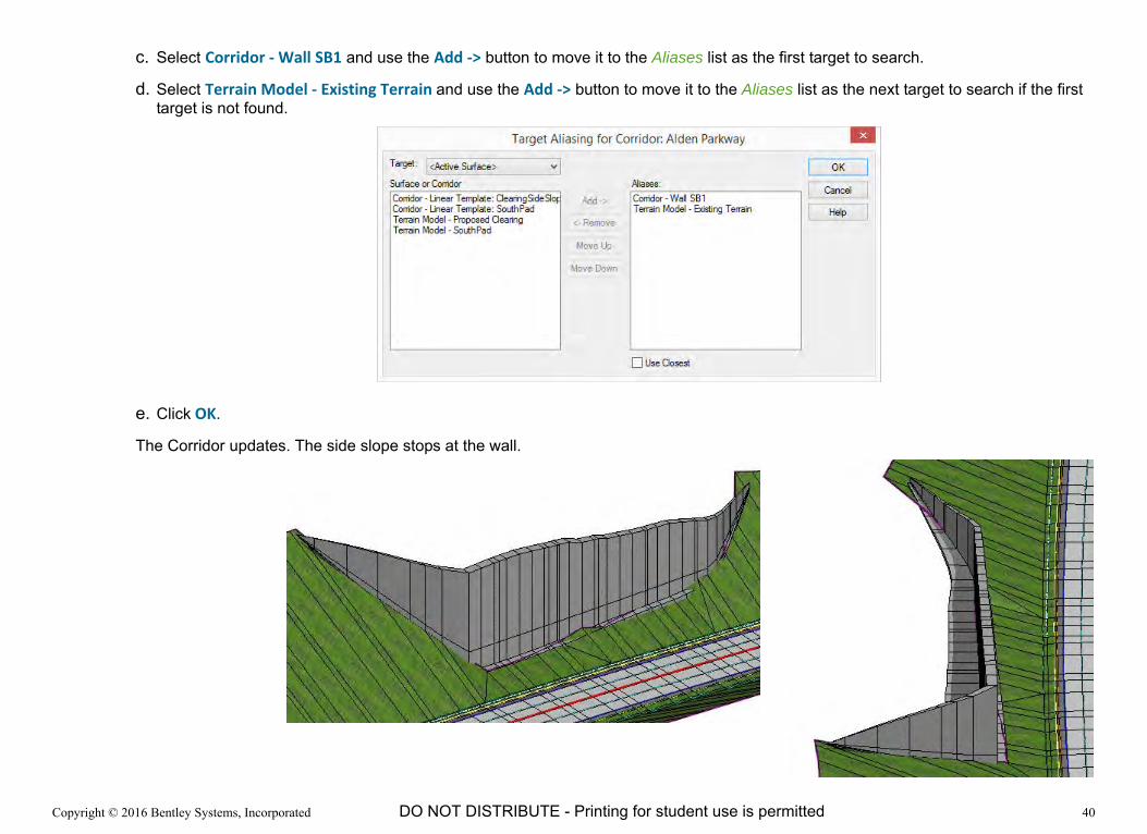
c. Select Corridor ‐ Wall SB1 and use the Add ‐> button to move it to the Aliases list as the first target to search.
d. Select Terrain Model ‐ Existing Terrain and use the Add ‐> button to move it to the Aliases list as the next target to search if the first target is not found.
e. Click OK.
The Corridor updates. The side slope stops at the wall.

Copyright © 2016 Bentley Systems, Incorporated 41DO NOT DISTRIBUTE - Printing for student use is permitted
Targeting Another Corridor
1. Zoom to the clearing to the south of the wall. Our design corridor needs to target this clearing.
2. Use Target Aliasing to tell the Corridor about this clearing.
a. Select Define Target Aliasing.
b. If prompted, select the corridor.
c. Add the following surface and corridor to the Aliases list.
Terrain Model ‐ Proposed Clearing
Corridor ‐ Linear Template: ClearningSideSlope
d. The search order of the Aliases list is important. Use the Move Up and Move Down buttons to adjust the list to search in the following order.
Corridor - Wall SB1
Terrain Model - Proposed Clearing
Corridor - Linear Template, ClearingSideSlope
Terrain Model - Existing Terrain
e. Click OK.

Copyright © 2016 Bentley Systems, Incorporated 42DO NOT DISTRIBUTE - Printing for student use is permitted
Exercise 6: Overriding End Conditions
DescriptionEnd Conditions are designed to be versatile and flexible, but there will be times that a completely different solution is required. End Condition Overrides are used to place a new solution along a range of stations.
In this exercise you will override an end condition and place a brow ditch along the top of a cut slope.
Skills Taught Add a Cut Slope with a Perimeter/Brow Ditch along a length of the corridor
Copyright © 2016 Bentley Systems, Incorporated 43DO NOT DISTRIBUTE - Printing for student use is permitted
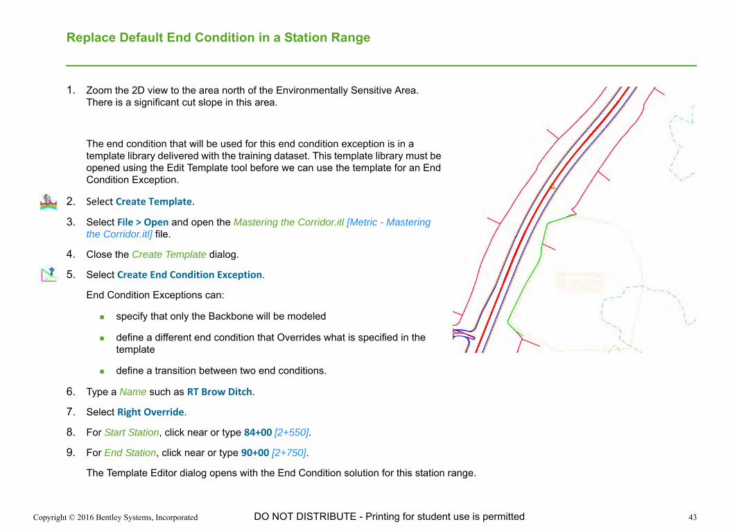
Replace Default End Condition in a Station Range
1. Zoom the 2D view to the area north of the Environmentally Sensitive Area. There is a significant cut slope in this area.
The end condition that will be used for this end condition exception is in a template library delivered with the training dataset. This template library must be opened using the Edit Template tool before we can use the template for an End Condition Exception.
2. Select Create Template.
3. Select File > Open and open the Mastering the Corridor.itl [Metric - Mastering the Corridor.itl] file.
4. Close the Create Template dialog.
5. Select Create End Condition Exception.
End Condition Exceptions can:
specify that only the Backbone will be modeled
define a different end condition that Overrides what is specified in the template
define a transition between two end conditions.
6. Type a Name such as RT Brow Ditch.
7. Select Right Override.
8. For Start Station, click near or type 84+00 [2+550].
9. For End Station, click near or type 90+00 [2+750].
The Template Editor dialog opens with the End Condition solution for this station range.

Copyright © 2016 Bentley Systems, Incorporated 44DO NOT DISTRIBUTE - Printing for student use is permitted
10. Right-click in the editing window and select Delete Components.
11. Press the Data button and drag the cursor through the right side End Conditions.
NOTE: The deleted components highlight in a different color but do not disappear from the view.
12. Expand the Template Library Tree and select Ditch Cut Tight
13. Single-click (do not double-click) on the Ditch Cut Tight template name and drag it to the outside of the grass, ensuring that it snaps to the point (RT_FILL_TOP).
14. Test the solution.
15. Click OK.
The Corridor updates.
Copyright © 2016 Bentley Systems, Incorporated 45DO NOT DISTRIBUTE - Printing for student use is permitted
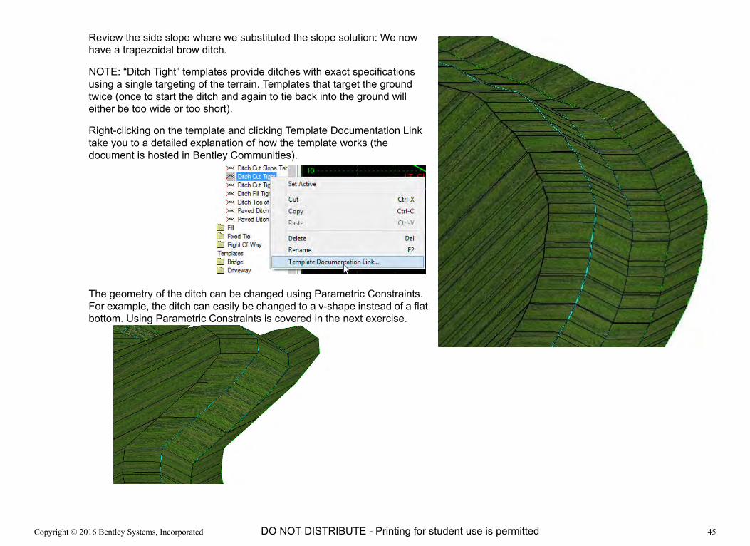
Review the side slope where we substituted the slope solution: We now have a trapezoidal brow ditch.
NOTE: “Ditch Tight” templates provide ditches with exact specifications using a single targeting of the terrain. Templates that target the ground twice (once to start the ditch and again to tie back into the ground will either be too wide or too short).
Right-clicking on the template and clicking Template Documentation Link take you to a detailed explanation of how the template works (the document is hosted in Bentley Communities).
The geometry of the ditch can be changed using Parametric Constraints. For example, the ditch can easily be changed to a v-shape instead of a flat bottom. Using Parametric Constraints is covered in the next exercise.

Copyright © 2016 Bentley Systems, Incorporated 46DO NOT DISTRIBUTE - Printing for student use is permitted
Exercise 7: Adjusting Template Geometry Along a Corridor
DescriptionTemplates represent typical geometry which can be overridden as necessary. We learned one way to override them earlier with point controls which can use geometry element to override template point positions. This is very powerful, especially for non-constant changes such as tapering lane widths.
Another way to override the default geometry along the corridor is using Parametric Constraints. Parametric Constraints use Labels assigned to constraints when templates are defined. These Labels can then be assigned values to override the default values specified in the template. The Label values can be constant or can change along a corridor.
For example, a shoulder could be widened by assigning a Shoulder Width of 8’ [2.5m] at Station 40+00 [1+120] and a Shoulder Width of 10’ [3.0m] at Station 41+00 [1+250]. Keep in mind that the override only is honored within the range defined by the Parametric Constraint. If you wanted the shoulder to continue at a width of 10, you would need to define another Parametric Constraint from Station 41+00 [1+250] to the end of the corridor.Another example would be to override the depth of the Aggregate from the default specified in the template. If the aggregate depth differs along the project multiple Parametric Constraints can be defined.
In this exercise you will define these adjustments in the this exercise and confirm them in Cross Section View.
Skills Taught Override the Default Brow Ditch Geometry
Use Parametric Constraints to widen a shoulder
Use Parametric Constraints to thicken the pavement aggregate
Parametric Label Start Station Start Value Stop Station Stop ValueShldr_Asph_Surf_Width 40+00 8 41+00 10
Shldr_Asph_Surf_Width 41+00 10 9999+99 10
Pvmt_Conc_Aggr_Depth 0+00 -0.5 41+99 -0.5
Pvmt_Conc_Aggr_Depth 42+00 -1.0 End -1.0

Copyright © 2016 Bentley Systems, Incorporated 47DO NOT DISTRIBUTE - Printing for student use is permitted
Adjusting the Geometry of the Ditch
What if a different geometric shape is desired for the ditch? What if instead of a flat bottom, a v-shaped ditch is required. What if different values are needed for the side slopes?
A well defined templates use Parametric Labels for key components that may change. In this example our template has Parametric Labels defined for the geometric properties such as the ditch bottom width, and the slopes of the sides of the ditch and the slope of the cut itself.
1. Define a Parametric Constraint to set the ditch bottom to a v-shape.
a. Select Create Parametric Constraint.
b. If prompted, select the corridor.
c. Set the Start Station to 84+00 [2+550].
d. Set the Stop Station to 90+00 [2+750] (the limits of our brow ditch).
e. Select Cut_Bottom_Width as the Constraint Label.
TIP: Typing cut into the heads up display selects that part of the list and the Up and Down arrow keys can then be used more easily to select the desired name.
The Cut_Bottom_Width label represents the width of the ditch bottom. We will set it to 0.1, which is close enough to zero for the ditch to be v-shaped.
f. Set the Start Value to 0.1.
g. Set the Stop Value to 0.1.
The corridor updates with a v-shaped ditch.
Copyright © 2016 Bentley Systems, Incorporated 48DO NOT DISTRIBUTE - Printing for student use is permitted
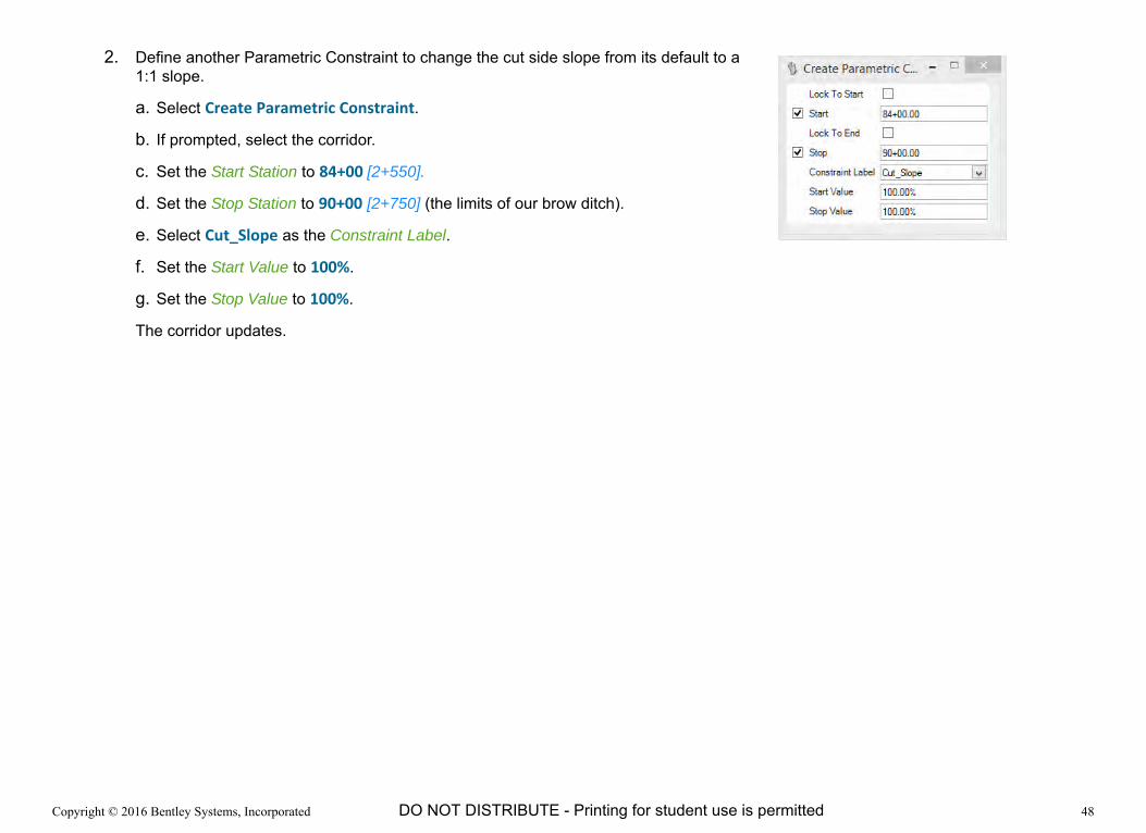
2. Define another Parametric Constraint to change the cut side slope from its default to a 1:1 slope.
a. Select Create Parametric Constraint.
b. If prompted, select the corridor.
c. Set the Start Station to 84+00 [2+550].
d. Set the Stop Station to 90+00 [2+750] (the limits of our brow ditch).
e. Select Cut_Slope as the Constraint Label.
f. Set the Start Value to 100%.
g. Set the Stop Value to 100%.
The corridor updates.

Copyright © 2016 Bentley Systems, Incorporated 49DO NOT DISTRIBUTE - Printing for student use is permitted
Widen the Shoulder
We will use 100’ [30m] to widen the shoulder from its nominal width of 4’ [1.2m] to 10’ [3.0m] on the right side. The details will conform to the data in this table.
1. Define a Parametric Constraint to widen the shoulder.
a. Select Create Parametric Constraint.
b. If prompted, select the corridor.
c. Start Station: 40+00 [1+120]
d. Stop Station: 41+00 [1+250]
e. Constraint Label: Shldr_Asph_Surf_Width
f. Start Value: 4 [1.2]
g. Stop Value: 10 [3.0]
The corridor updates.
Note the shoulder transitions out to it full width and then reverts to its nominal width after the Stop Station.
Parametric Label Start Station Start Value Stop Station Stop ValueShldr_Asph_Surf_Width 40+00 4 41+00 10
Shldr_Asph_Surf_Width 41+00 10 9999+99 10

Copyright © 2016 Bentley Systems, Incorporated 50DO NOT DISTRIBUTE - Printing for student use is permitted
1. Define a Parametric Constraint to continue the widened shoulder to the end of the project.
a. Select Create Parametric Constraint.
b. If prompted, select the corridor.
c. Start Station: 41+00 [1+250]
d. Stop Station: click the Alt key to Lock to End and Data point to accept.
e. Constraint Label: Shldr_Asph_Surf_Width
f. Start Value: 10 [3.0]
g. Stop Value: 10 [3.0]
The corridor updates.
Note the shoulder transitions out to it full width and then reverts to its nominal width after the Stop Station.
2. Confirm the shoulder width in the Cross Sections.
a. If a cross section view is not currently open, create the cross sections using the Open Cross Section Model tool.
b. Select Show Place Dimension and place a dimension between the EOP and Shoulder point.
c. Select the Station value in the Cross Section view and key in 41+00 [1+250].
d. Browse through the cross sections and verify the shoulder widens as desired.

Copyright © 2016 Bentley Systems, Incorporated 51DO NOT DISTRIBUTE - Printing for student use is permitted
Thicken the Aggregate
In this exercise you will override the pavement Aggregate depth according to the table below.
1. Define a Parametric Constraint to continue the widened shoulder. to the end of the project.
a. Select Create Parametric Constraint.
b. If prompted, select the corridor.
c. Start Station: click the Alt key to Lock to Start and Data point to accept.
d. Stop Station: 41+99 [1+279.9]
e. Constraint Label: Pvmt_Conc_Aggr_Depth
f. Start Value: ‐0.5 [-0.15]
g. Stop Value: ‐0.5 [-0.15]
2. Define a Parametric Constraint to continue the widened shoulder. to the end of the project.
a. Select Create Parametric Constraint.
b. If prompted, select the corridor.
c. Start Station: 42+00 [1+280]
d. Stop Station: click the Alt key to Lock to End and Data point to accept.
e. Constraint Label: Pvmt_Conc_Aggr_Depth
f. Start Value: ‐1 [-0.3]
Stop Value: ‐1 [-0.3]
Parametric Label Start Station Start Value Stop Station Stop ValuePvmt_Conc_Aggr_Depth 0+00 -0.5 41+99 -0.5
Pvmt_Conc_Aggr_Depth 42+00 -1.0 End -1.0
Copyright © 2016 Bentley Systems, Incorporated 52DO NOT DISTRIBUTE - Printing for student use is permitted
Exercise 8: Assigning Superelevation
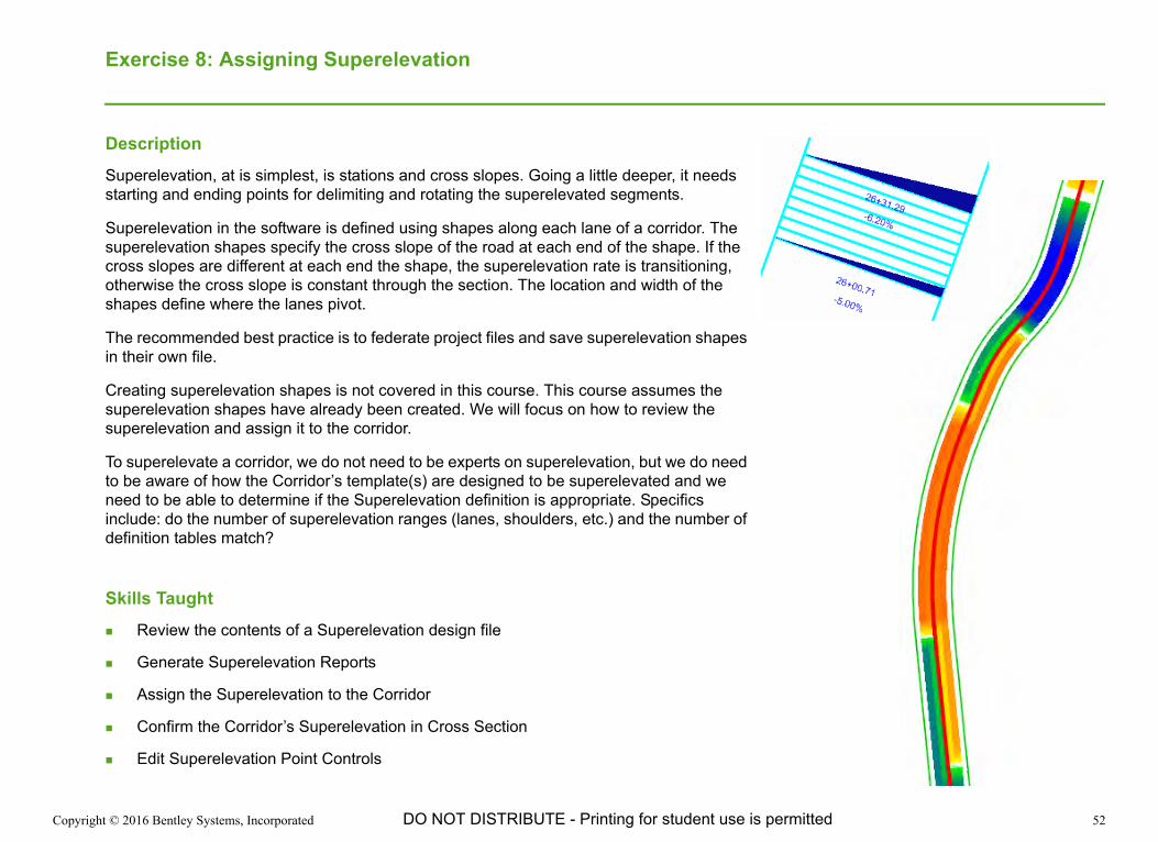
DescriptionSuperelevation, at is simplest, is stations and cross slopes. Going a little deeper, it needs starting and ending points for delimiting and rotating the superelevated segments.
Superelevation in the software is defined using shapes along each lane of a corridor. The superelevation shapes specify the cross slope of the road at each end of the shape. If the cross slopes are different at each end the shape, the superelevation rate is transitioning, otherwise the cross slope is constant through the section. The location and width of the shapes define where the lanes pivot.
The recommended best practice is to federate project files and save superelevation shapes in their own file.
Creating superelevation shapes is not covered in this course. This course assumes the superelevation shapes have already been created. We will focus on how to review the superelevation and assign it to the corridor.
To superelevate a corridor, we do not need to be experts on superelevation, but we do need to be aware of how the Corridor’s template(s) are designed to be superelevated and we need to be able to determine if the Superelevation definition is appropriate. Specifics include: do the number of superelevation ranges (lanes, shoulders, etc.) and the number of definition tables match?
Skills Taught Review the contents of a Superelevation design file
Generate Superelevation Reports
Assign the Superelevation to the Corridor
Confirm the Corridor’s Superelevation in Cross Section
Edit Superelevation Point Controls
Copyright © 2016 Bentley Systems, Incorporated 53DO NOT DISTRIBUTE - Printing for student use is permitted
Review the Corridor to be Superelevated
Let’s take a look at the corridor’s templates.
For this superelevation exercise we are going to use a slightly different Corridor stored in a different dgn file. This corridor uses a slightly different template and has standard side slopes. It is referencing the same Geometry and other files as we have used in the previous exercises.
1. Open the Corridor_for_Superelevation.dgn [Metric - Corridor_for_Superelevation.dgn] file.
2. Select the corridor.
3. In the Element Information dialog, expand the Corridor and Templates.
4. Right-click on the Template Drop and click Edit Template Drop.
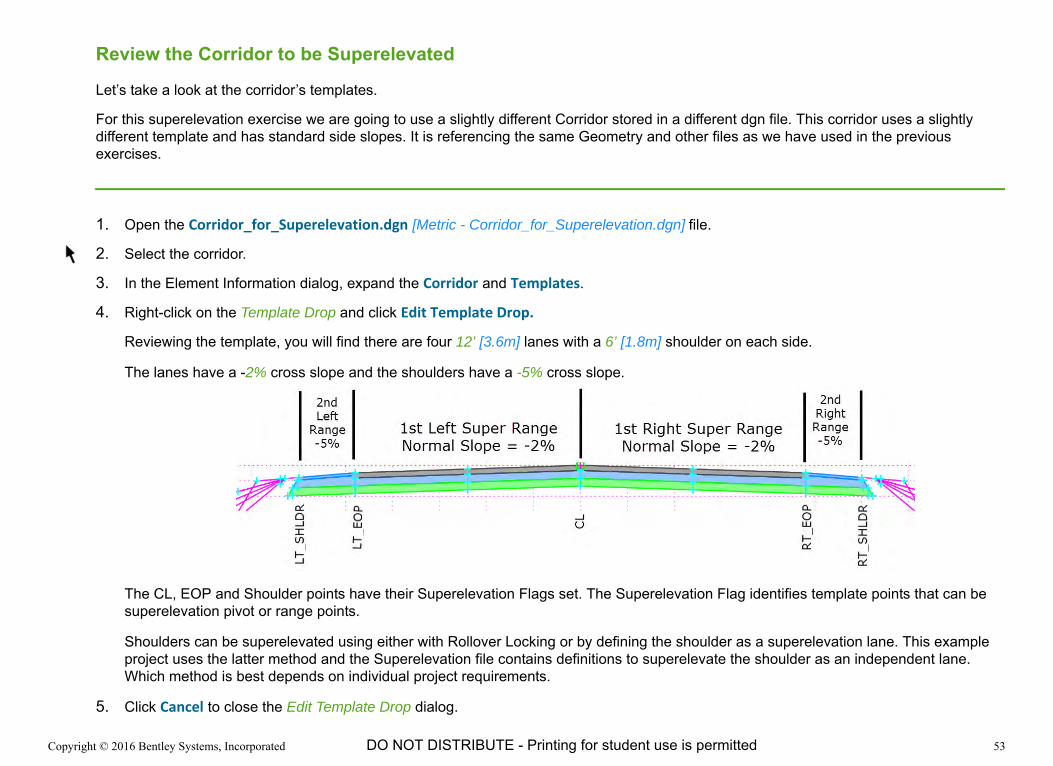
Reviewing the template, you will find there are four 12’ [3.6m] lanes with a 6’ [1.8m] shoulder on each side.
The lanes have a -2% cross slope and the shoulders have a -5% cross slope.
The CL, EOP and Shoulder points have their Superelevation Flags set. The Superelevation Flag identifies template points that can be superelevation pivot or range points.
Shoulders can be superelevated using either with Rollover Locking or by defining the shoulder as a superelevation lane. This example project uses the latter method and the Superelevation file contains definitions to superelevate the shoulder as an independent lane. Which method is best depends on individual project requirements.
5. Click Cancel to close the Edit Template Drop dialog.
Copyright © 2016 Bentley Systems, Incorporated 54DO NOT DISTRIBUTE - Printing for student use is permitted
Review the Superelevation File
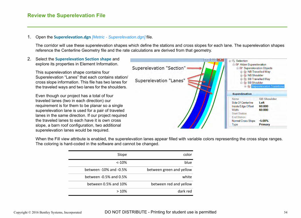
1. Open the Superelevation.dgn [Metric - Superelevation.dgn] file.
The corridor will use these superelevation shapes which define the stations and cross slopes for each lane. The superelevation shapes reference the Centerline Geometry file and the rate calculations are derived from that geometry.
2. Select the Superelevation Section shape and explore its properties in Element Information.
This superelevation shape contains four Superelevation “Lanes” that each contains station/cross slope information. This file has two lanes for the traveled ways and two lanes for the shoulders.
Even though our project has a total of four traveled lanes (two in each direction) our requirement is for them to be planar so a single superelevation lane is used for a pair of traveled lanes in the same direction. If our project required the traveled lanes to each have it is own cross slope, a barn roof configuration, two additional superelevation lanes would be required.
When the Fill view attribute is enabled, the superelevation lanes appear filled with variable colors representing the cross slope ranges. The coloring is hard-coded in the software and cannot be changed.
Slope color
<‐10% blue
between ‐10% and ‐0.5% between green and yellow
between ‐0.5% and 0.5% white
between 0.5% and 10% between red and yellow
> 10% dark red

Copyright © 2016 Bentley Systems, Incorporated 55DO NOT DISTRIBUTE - Printing for student use is permitted
3. Select Superelevation Report to create a report of the superelevation stations, cross slopes and the parameters that were used to calculate the superelevation rates.
4. If prompted, select the Superelevation Section shape.

Copyright © 2016 Bentley Systems, Incorporated 56DO NOT DISTRIBUTE - Printing for student use is permitted
5. Select Superelevation Editor to open the Superelevation Editor.
6. If prompted, select the Superelevation Section shape.
The top of the dialog shows the superelevation diagram and the bottom shows a tabular representation of the superelevation shapes.
Copyright © 2016 Bentley Systems, Incorporated 57DO NOT DISTRIBUTE - Printing for student use is permitted
Assigning Superelevation to the Corridor
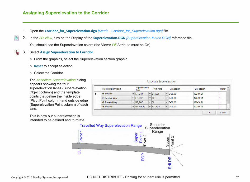
1. Open the Corridor_for_Superelevation.dgn [Metric - Corridor_for_Superelevation.dgn] file.
2. In the 2D View, turn on the Display of the Superelevation.DGN [Superelevation-Metric.DGN] reference file.
You should see the Superelevation colors (the View’s Fill Attribute must be On).
3. Select Assign Superelevation to Corridor.
a. From the graphics, select the Superelevation section graphic.
b. Reset to accept selection.
c. Select the Corridor.
The Associate Superelevation dialog appears showing the four superelevation lanes (Superelevation Object column) and the template points that define the inside edge (Pivot Point column) and outside edge (Superelevation Point column) of each lane.
This is how our superelevation is intended to be defined and to rotate.

Copyright © 2016 Bentley Systems, Incorporated 58DO NOT DISTRIBUTE - Printing for student use is permitted
d. Verify that the point assignments in the Associate Superelevation dialog match the following values. Use the pull-downs to assign them properly if any changes are required.
e. Click OK.
The corridor is processed applying the superelevation.
Superelevation Object Superelevation Point
Pivot Point
SB Shoulder LT_SHDR LT_EOP
SB Traveled Way LT_EOP CL
NB Traveled Way RT_EOP CL
NB Shoulder RT_SHLD RT_EOP
Copyright © 2016 Bentley Systems, Incorporated 59DO NOT DISTRIBUTE - Printing for student use is permitted
Verify that the Corridor is Superelevated
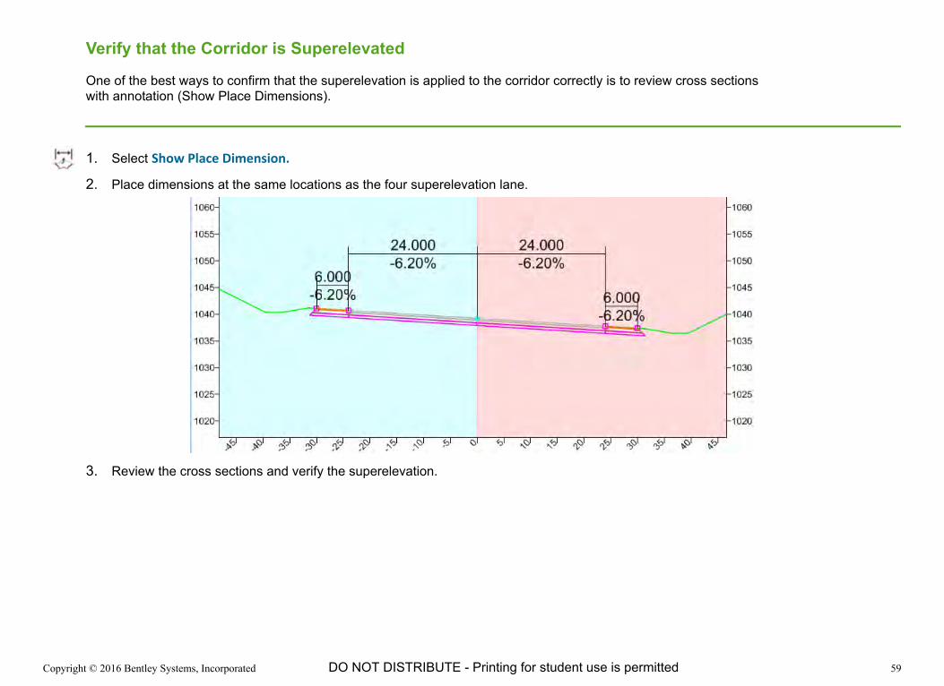
One of the best ways to confirm that the superelevation is applied to the corridor correctly is to review cross sections with annotation (Show Place Dimensions).
1. Select Show Place Dimension.
2. Place dimensions at the same locations as the four superelevation lane.
3. Review the cross sections and verify the superelevation.
Copyright © 2016 Bentley Systems, Incorporated 60DO NOT DISTRIBUTE - Printing for student use is permitted
Editing the Shoulder Superelevation Control
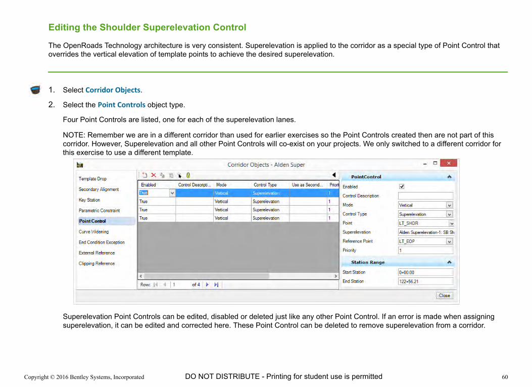
The OpenRoads Technology architecture is very consistent. Superelevation is applied to the corridor as a special type of Point Control that overrides the vertical elevation of template points to achieve the desired superelevation.
1. Select Corridor Objects.
2. Select the Point Controls object type.
Four Point Controls are listed, one for each of the superelevation lanes.
NOTE: Remember we are in a different corridor than used for earlier exercises so the Point Controls created then are not part of this corridor. However, Superelevation and all other Point Controls will co-exist on your projects. We only switched to a different corridor for this exercise to use a different template.
Superelevation Point Controls can be edited, disabled or deleted just like any other Point Control. If an error is made when assigning superelevation, it can be edited and corrected here. These Point Control can be deleted to remove superelevation from a corridor.