
Bearing Installation and Maintenance SKF
130
Bearing Installation and Maintenance Guide Includes Shaft and Housing Fits 140-710 Bearing Installation and Maintenance Guide
-
Upload
mohamed-lotfy-ali-elsherbeeny -
Category
Documents
-
view
614 -
download
48
Transcript of Bearing Installation and Maintenance SKF

® SKF is a registered trademark of SKF USA Inc.Although care has been taken to assure the accuracy of this publication, SKF does not assume any liability for errors or omissions.
© 2001 SKF USA Inc. Publication 140-710 (30M/CW 4/2001) Version 4/2001 Printed in USA
SKF Services Division1510 Gehman RoadKulpsville, PA 19443(215) 513-4400
www.skfusa.com
Bearing Installationand Maintenance GuideIncludes Shaft and Housing Fits
140-710
Bearing Installation and M
aintenance Guide

Bearing Types....................................................... 2-6
Bearing Terminology ............................................ 7
Mounting and Dismounting of BearingsFitting Practice ............................................................... 8Internal Bearing Clearance ............................................ 8Mounting Methods...........................................................8
Cold Mounting.......................................................... 8Temperature Mounting............................................. 8
Heating the Bearing............................................. 8Heating the Housing............................................ 9
Oil Injection (Hydraulic) Mounting............................ 9Mounting on the Shaft .................................................... 9
Cylindrical Bore Bearings ........................................ 9Tapered Bore Bearings.......................................... 10Tapered Shaft Mounting......................................... 11Adapter Mounting ............................................. 11-12
Mounting in the Housing .............................................. 13Bearings Requiring Axial Adjustment........................... 13SKF Hydraulic Drive-up Method................................... 16Mounting CARB™ Toroidal Roller Bearings................. 21
Cylindrical Bore ..................................................... 22Tapered Bore ......................................................... 22
Dismounting ................................................................. 22Guidelines for Bearing Assembly ................................. 28Maintenance and Inspection ................................... 28-30Can the Bearing Be Used Again? ................................ 31
Shaft and Housing FitsSuitable Fits ................................................................. 32Dimensional Form and Running Accuracy................... 33Surface Roughness of Bearing Seatings ..................... 33Tables (see p. 123-125 for list) ................................ 34-63
LubricationFunctions of Lubrication ............................................... 64Oil Lubrication .............................................................. 64
Selection of Oil....................................................... 66Relubrication Intervals ........................................... 66Oil Supply Systems................................................ 66
Oil Bath.............................................................. 66Circulating Systems..................................... 66, 69Wick Feed.......................................................... 69Oil Mist from Separate Mist Generator .............. 70Air-Oil Lubrication.............................................. 70
Grease Lubrication....................................................... 72Grease Classification............................................. 72Testing ................................................................... 73Operating Conditions ............................................. 74Lubrication and Maintenance ................................ 75
Relubrication ..................................................... 75
Relubrication Intervals....................................... 75Replenishment....................................................... 75Grease Supply Systems ........................................ 75
Housings without Grease Fittings...................... 75Housings with Grease Fittings..................... 75, 77Grease Chamber Lubrication ............................ 77Grease Quantity Regulator................................ 77
Comparative Advantages of Oil and Grease................ 78High Temperature Applications .................................... 78Minimum Friction Applications...................................... 78Protection against Moisture.......................................... 78Protection of Idle Machinery ........................................ 79Cleaning.................................................................. 79-80CARB™ Toroidal Roller Bearing Lubrication .......... 80-82SKF Solid Oil™ ............................................................ 83
Troubleshooting ............................................ 84-103Trouble Conditions and Their Solutions
Overheated Bearing ......................................... 86-88Noisy Bearing ................................................... 88-92Too Frequent Replacements............................. 92-95Vibration ........................................................... 96-97Unsatisfactory Performance of Equipment ..... 98-100Bearing Loose on Shaft ....................................... 101Shaft Hard to Turn ........................................ 101-103
Bearing Failures and Their CausesSpalling ...................................................................... 104Patterns of Load Zones andTheir Meaning in Bearing Damage ..................... 105-107Failure Due to Defective Shaft/Housing Seats ........... 107Misalignment....................................................... 107-109Faulty Mounting Practice..................................... 109-110Damage due to Improper Fit ............................... 110-111Inadequate or Unsuitable Lubricants .................. 111-113Ineffective Sealing............................................... 113-114Vibration.............................................................. 114-115Passage of Electric Current throughthe Bearing.......................................................... 115-116
Bearing Maintenance Products .................... 117
Bearing Mounting and Dismounting Methods ...................................... 118
Reliability Maintenance Institute .......... 119-120Maintenance Road Show..................................... 121Videos.................................................................. 121SKF Authorized Distributor Training..................... 122
Index of Tables and Figures ................... 123-125
Information Order Form................................... 127
Table of Contents

2
Bearing TypesEach type of bearing has characteristic properties which make it particularly suitable for certain applications. The main factors to be considered when selectingthe correct type are:
● precision required● noise factor● internal clearance● materials and cage design● bearing arrangement● seals
● available space● magnitude and direction of load
(radial, axial, or combined)● speed● misalignment● mounting and dismounting proce-
dures
Radial bearings
Deep groove ball bearingssingle row (1)
with shield(s) or seal(s)with snap ring groove in outer ring(and snap ring)
double row (2)
Self-aligning ball bearingswith cylindrical (3) or tapered borewith sealswith extended inner ring (4)
Angular contact ball bearingssingle row (5)
for paired mountingprecision bearings (6)
double row (7)with shields or seals
Four-point contact ball bearings (8)
1 2
3 4
5 6
7 8

Radial bearings
CARBTM toroidal roller bearing (9)caged or full complement version
with or without seals
Cylindrical roller bearingssingle row
NU type (10)N type (11)
NJ type (12)NJ type with HJ angle ring (13)NUP type (14)
double row NNU type (15)NN type (16)
four-row with cylindrical (17) or tapered bore
Full complement cylindrical roller bearingssingle row (18)double row with (19) or without sealsmulti-row
Cross cylindrical roller bearings (20)
3
10 11
12 13 14
15 16 17
18 19
20
9

Radial bearings
Needle roller bearingsDrawn cup needle roller bearings
with open (21) and closed endsNeedle roller bearings with flanges
with or without inner ring (22), with seal(s)Needle roller bearings without flanges
with or without inner ring
Needle roller and cage assemblies (23)Combined needle roller bearings (24)Alignment needle roller bearings
Spherical roller bearingswith cylindrical (25) or tapered bore
Taper roller bearingssingle row (26)double row (27)
four row (28)
Cross taper roller bearings (29)
4
Bearing types
21 22
23
25
24
26
29
28
27

Thrust bearings
Thrust ball bearingssingle direction
with flat housing washer (30)with sphered housing washer and seating ring
double directionwith flat housing washerswith sphered housing washers and seating rings (31)
Angular contact thrust ball bearingssingle direction (32)double direction (33)
Cylindrical roller thrust bearings (34)
Needle roller thrust bearings (35)
Spherical roller thrust bearings (36)
Taper roller thrust bearingssingle direction (37)double direction (38)
5
30 31
32
34
35
36
33
37 38
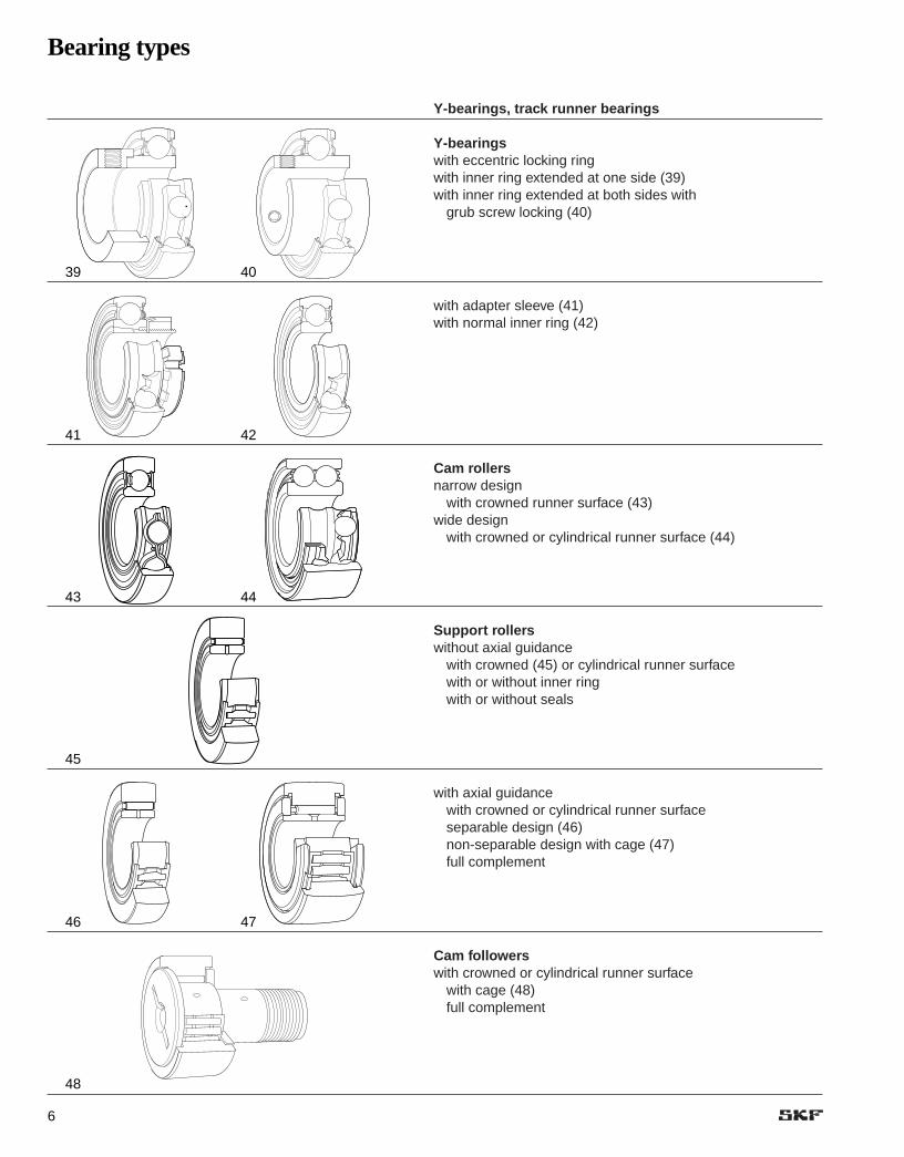
Y-bearings, track runner bearings
Y-bearings with eccentric locking ringwith inner ring extended at one side (39)with inner ring extended at both sides with
grub screw locking (40)
with adapter sleeve (41)with normal inner ring (42)
Cam rollersnarrow design
with crowned runner surface (43)wide design
with crowned or cylindrical runner surface (44)
Support rollerswithout axial guidance
with crowned (45) or cylindrical runner surfacewith or without inner ringwith or without seals
with axial guidancewith crowned or cylindrical runner surfaceseparable design (46)non-separable design with cage (47) full complement
Cam followerswith crowned or cylindrical runner surface
with cage (48) full complement
6
Bearing types
39 40
41 42
43
45
44
46
48
47

11
Self-AligningBall Bearing
Single Row DeepGroove Ball Bearing
Angular ContactBall Bearing
Double Row DeepGroove Ball Bearing
SphericalRoller Bearing
CylindricalRoller Bearing
TaperedRoller Bearing
Spherical RollerThrust Bearing
BORE
WIDTH
OUTSIDEDIAMETER
5 6
12
3
4
28
7
8
28
9
10
28
28
21
20
22 23
24
25
26
27
28
16
17 18
19
12 13 14
15
28
28
30 32
33
Bearing Terminology
7
The illustrations below identify the bearing parts of eightSKF® basic bearing types. The terms used conform with theterminology section of the American Bearing Manufacturers
Association, Inc. (ABMA) standards, and are generallyaccepted by anti-friction bearing manufacturers.
1. Inner Ring2. Inner Ring Corner3. Inner Ring Land4. Outer Ring Land5. Outer Ring6. Ball7. Counter Bore8. Thrust Face
9. Outer Ring Raceway10. Inner Ring Raceway11. Outer Ring Corner12. Spherical Roller13. Lubrication Feature
(Holes and Groove) (W33)14. Spherical Outer Ring Raceway15. Floating Guide Ring16. Inner Ring Side Face
17. Outer Ring Side Face18. Cylindrical Roller19. Outer Ring Flange20. Cone Front Face21. Cone Front Face Flange22. Cup (Outer Ring)23. Tapered Roller24. Cone Back Face Flange
25. Cone Back Face26. Cone (Inner Ring)27. Undercut28. Cage30. Face32. Shaft Washer (Inner Ring)33. Housing Washer (Outer Ring)

Mounting and Dismounting of Bearings
8
Nearly all rolling bearing applicationsrequire the use of an interference fit on at least one of the bearing rings,usually the inner. Consequently, allmounting methods are based onobtaining the necessary interferenceswithout undue effort, and with no riskof damage to the bearing.
Fitting Practice
A ball or roller bearing has extremelyaccurate component parts which fittogether with very close clearances.The inner ring bore and the outer ringoutside diameter are manufacturedwithin close limits to fit their respectivesupporting members — the shaft andhousing. It follows that the shaft andthe housing must also be machined tosimilar close limits. Only then will therequired fits be obtained when thebearing is mounted. Shaft and housingfit tables are shown in a separatechapter beginning on page 32.
Internal Bearing Clearance
It is evident that a press (or interfer-ence) fit between the parts will stretchthe inner ring. This holds true whenmounting the bearing directly on theshaft or by means of an adaptersleeve. Thus, there will be a tendencyto reduce the initial internal radialclearance in the bearing.
However, bearings are designed insuch a way that if the recommendedshaft fits are used and operating temperatures have been taken intoaccount, the internal clearance remain-ing after mounting the bearing will besufficient for proper operation.
Mounting Methods
Three basic mounting methods areused, the choice depending on factorssuch as the number of mountings,bearing type and size, magnitude ofthe interferences and, possibly, theavailable tools. SKF supplies tools forall mounting methods described here.For more details, see the SKF BearingMaintenance Tools Catalog (711-639).
1. Cold Mounting
Mounting of a bearing without heatingit first is the most basic and directmounting method. A pressure force of sufficient magnitude is appliedagainst the face of the ring having theinterference fit. This method is mostsuitable for cylindrical bore bearings up to about 70 mm bore and fortapered bore bearings up to about 240 mm bore.
Sometimes the interference speci-fied for a cylindrical bore bearing ofless than 70 mm bore is great enoughto warrant the use of one of the othermethods to be described. Three othersituations may make it impractical orinadvisable to cold mount a bearing:
● When the bearing face againstwhich the pressing force is to beapplied, either directly or through anadjacent part, is inaccessible.
● When the distance through whichthe bearing must be displaced inorder to seat is too great.
● When the shaft or housing seatingmaterial is so soft that there is riskof permanently deforming it duringthe mounting process.
2. Temperature Mounting
Temperature mounting is the techniqueof obtaining an interference fit by firstintroducing a temperature differentialbetween the parts to be fitted, thusfacilitating their assembly. The neces-sary temperature differential can beobtained in one of three ways:
● Heating one part (most common)
● Cooling one part
● Simultaneously heating one part andcooling the other
Heating the Bearing
Heat mounting is suitable for all medi-um and large size straight bore bear-ings, and for small bearings with cylin-drical seating arrangements. Normallya bearing temperature of 150°F aboveshaft temperature (not to exceed 250°F)provides sufficient expansion for mount-ing. As the bearing cools, it contractsand tightly grips the shaft. It’s importantto heat the bearing uniformly, and toregulate heat accurately, since excessheat destroys a bearing’s metallurgical properties, softening the bearing. Never heat a bearing using an openflame, such as a blowtorch.
Heat mounting reduces the risk of bearing or shaft damage duringinstallation, because the bearing canbe slid easily onto the shaft.Appropriate electric-heat bearingmounting devices include inductionheaters, ovens, hot plates and heatingcones. Of these, induction heaters andovens are the most convenient, andheaters the fastest, devices to use.

9
Hot oil baths have traditionally beenused to heat bearings, but are no longerrecommended except when unavoid-able. In addition to health and safetyconsiderations are the environmentalissues about oil disposal, which canbecome costly.
If hot oil bath is used, both the oiland the container must be absolutelyclean. Oil previously used for someother purpose should be thoroughly filtered. Quenching oil having a minimumflash point of 300°F, transformer oil, or10% to 15% water soluble oil, are satisfactory heating mediums. Whenusing an oil bath, temperature monitor-ing is important not only to preventbearing damage, but also to preventthe oil from reaching flash point.
The quantity of oil used in a bathshould be plentiful in relation to the volume of the bearing. An insufficientquantity heats and cools too rapidly,thus introducing the risk of inadequate-ly or unevenly heating the bearing. It is also difficult in such a case todetermine when and if the bearing hasreached the same temperature as theoil. To avoid hot spots on the bearing, itis good practice to install a rack at thebottom of the bath. Sufficient timeshould be allowed for the entire bear-ing to reach the correct temperature.The bath should cover the bearing.
Heating the Housing
The bearing housing may require heating in cases where the bearingouter ring is mounted with an interfer-ence fit in the housing. Since the outerring is usually mounted with a lighterinterference fit, the temperature differ-ence required is usually less than thatrequired for an inner ring.
A bearing housing may be heated inseveral ways. If the size of the housingbore permits, an inspection lamp canbe inserted, the heat from the lampusually being sufficient to produce thedesired expansion. In some cases theshape and size of the housing allowthe use of an electric furnace, but inother cases a hot oil bath is necessary.
3. Oil-Injection (Hydraulic) Mounting
This is a refined method for coldmounting a tapered bore bearing. It is
based on the injection of oil betweenthe interfering surfaces, thus greatlyreducing the required axial mountingforce. The pressure is generally sup-plied with a manually-operated recipro-cating pump. The required pressureseldom exceeds 10,000 psi, and isusually much less.
The oil used for oil-injection mountingshould be neither too thin nor too viscous. It is difficult to build up pres-sures with excessively thin oils, whilethick oils do not readily drain frombetween the fitting surfaces and requirea little more axial force for positioningthe bearing. This method cannot beused unless provided for in the designof the mounting. (Contact SKF forretrofitting details.)
Mounting on the Shaft
Cylindrical Bore Bearings
When mounted directly on the shaft,the inner ring should be locatedagainst a shaft shoulder of properheight (➔ fig ). This shoulder mustbe machined square with the bearing seat and a shaft fillet should be used.The radius of the fillet must clear the corner radius of the inner ring.Specific values for recommendedshoulder heights and fillet radii for each size bearing are given in thedimensional tables of all SKF products catalogs.
If the inner ring is loose on the shaft,creeping will occur. This will result inoverheating, excessive wear and contact erosion between the shaft and inner ring. Creep is described as the relative circumferential move-ment between the bearing bore andshaft surfaces.
Therefore a preventive measuremust be taken to eliminate creepingand its harmful results. Mount the innerring with a sufficient press fit on theshaft. This will help ensure that bothinner ring and shaft act as a unit androtate at the same speed. It is alsodesirable to use a locknut to clamp theinner ring against the shaft shoulder.
If the applied load is of a rotatingnature (for example, vibrating screenswhere unbalanced weights areattached to the shaft), then the outerring becomes the critical member. In
1
1. Shaft Fillet Too Large
2. Correct Shaft Fillet
3. Shaft Shoulder Too Small
4. Shaft Shoulder Too Large
5. Correct Shaft Shoulder Diameter
Fig 1

10
order to eliminate creeping in thiscase, the outer ring must be mountedwith a press fit in the housing. Therotating inner ring, when subjected to a rotating load, can be mounted with a slip fit on the shaft.
When the ring rotates in relation to the load, a tight fit is required.
Tapered Bore Bearings
The mounting of any tapered borebearing is affected by driving the bearing on its seat a suitable amount.
How to measure unmountedradial internal clearance of SKFtapered bore spherical rollerbearings (in inches)
Oscillate the inner ring in a circumferential direction to properlyseat the rollers. Measure the radialinternal clearance in the bearingby inserting progressively largerfeeler blades the full length of theroller between the most unloadedroller and the outer ring sphere.CAUTION: Do not roll over thefeeler blade, slide it through theclearance. Record the measure-ment on the largest size blade that will slide through. This is the unmounted radial internalclearance.
Repeat this procedure in two orthree other locations by resting thebearing on a different spot on itsO.D. and measuring over differentrollers in one row. Repeat theabove procedure for the other rowof rollers or measure each row alternately in the proceduredescribed above (See chart A).
This amount may be determined either by measuring the reduction ofinternal radial clearance or the axialdrive-up.
Drive-up is achieved with a force of sufficient magnitude applied directlyto the face of the ring with the interfer-ence fit. This force is generated withone of the following devices:
1. Threaded lock nut2. Bolted end plate3. Hydraulic nut4. Mounting sleeve
When using the internal radial clear-ance reduction method on tapered borespherical roller bearings, establish aninitial reference point by measuring theunmounted internal clearance using theinstructions shown with chart A.
The absolute values for reduction inclearance are shown in chart B.
Bore Dia. Normal C3 C4d(m) (in.) (in.) (in.)
Over Incl. Min. Max. Min. Max. Min. Max.
24 30 0.0012 0.0016 0.0016 0.0022 0.0022 0.003030 40 0.0014 0.0020 0.0020 0.0026 0.0026 0.003340 50 0.0018 0.0024 0.0024 0.0031 0.0031 0.0039
50 65 0.0022 0.0030 0.0030 0.0037 0.0037 0.004765 80 0.0028 0.0037 0,0037 0.0047 0.0047 0.005980 100 0.0031 0.0043 0.0043 0.0055 0.0055 0.0071
100 120 0.0039 0.0053 0.0053 0.0067 0.0067 0.0087120 140 0.0047 0.0063 0.0063 0.0079 0.0079 0.0102140 160 0.0051 0.0071 0.0071 0.0091 0.0091 0.0118
160 180 0.0055 0.0079 0.0079 0.0102 0.0102 0.0134180 200 0.0063 0.0087 0.0087 0.0114 0.0114 0.0146200 225 0.0071 0.0098 0.0098 0.0126 0.0126 0.0161
225 250 0.0079 0.0106 0.0106 0.0138 0.0138 0.0177250 280 0.0087 0.0118 0.0118 0.0154 0.0154 0.0193280 315 0.0094 0.0130 0.0130 0.0169 0.0169 0.0213
315 355 0.0106 0.0142 0.0142 0.0185 0.0185 0.0232355 400 0.0118 0.0157 0.0157 0.0205 0.0205 0.0256400 450 0.0130 0.0173 0.0173 0.0224 0.0224 0.0283
450 500 0.0146 0.0193 0.0193 0.0248 0.0248 0.0311500 560 0.0161 0.0213 0.0213 0.0268 0.0268 0.0343560 630 0.0181 0.0236 0.0236 0.0299 0.0299 0.0386
630 710 0.0201 0.0264 0.0264 0.0335 0.0335 0.0429710 800 0.0224 0.0295 0.0295 0.0378 0.0378 0.0480800 900 0.0252 0.0331 0.0331 0.0421 0.0421 0.0539
900 1000 0.0280 0.0366 0.0366 0.0469 0.0469 0.05981000 1120 0.0303 0.0406 0.0406 0.0512 0.0512 0.06571120 1250 0.0327 0.0441 0.0441 0.0559 0.0559 0.0720
Chart A — Unmounted Radial Internal Clearance of SKF Tapered Bore Spherical Roller Bearings (in inches)

Spherical Roller Bearing Axial Drive-up
The axial drive-up “S” is approximately:
● 16 times the reduction on 1:12taper for solid steel shafts
● 18 times the reduction on 1:12taper for sleeve mounting
● 39 times the reduction in 1:30taper for solid steel shafts
● 42 times the reduction on 1:30taper for sleeve mounting
Adapter Mounting
NOTE: Wipe preservative from theadapter O. D. and bore as well as thebearing bore. It may not be necessary toremove the preservative from the internalcomponents of the bearing unless thebearing will be lubricated by a circulating oil or oil mist system.
Step 1 —adapter sleeveRemove oil from the shaft to preventtransfer of oil to the bore of the adaptersleeve. Position adapter sleeve on shaft,thread outboard as indicated, to approxi-mate location with respect to requiredbearing centerline. Light oil applied to thesleeve outside diameter surface results ineasier bearing mounting and removal.(see ➔ fig )
Step 2 — bearingSpherical roller radial bearings —Measure the unmounted internal radialclearance in the bearing by inserting pro-gressively larger feeler blades the fulllength of the roller between the most verti-cal unloaded roller and the outer ringsphere. DO NOT roll the feeler bladethrough the clearance; slide it through.Record the measurement of the largestsize blade that will slide through. This isthe unmounted radial internal clearance.Wipe bearing bore and mount on adaptersleeve, starting with the large bore of theinner ring to match the taper of theadapter. With the bearing hand tight on the adapter sleeve, locate the bearing tothe proper axial position on the shaft. (DO NOT apply lockwasher at this timebecause drive-up procedure may damagelockwasher). Apply the locknut with the
4
11
S
CAUTION: Do not use the maximum reduction of radial internal clearance when the initialunmounted radial internal clearance is in the lower half of thetolerance range or where largetemperature differentials betweenthe bearing rings can occur inoperation. (See chart B).
Figure 2. Tapered Shaft Mounting (with locknut and hydraulic removal)
Figure 3. Tapered Bore Mounting: with adapter sleeve (left); with withdrawal sleeve (right).
Reduction inBore Diameter Radial Internal
d(mm) Clearance (in.)
Over Incl. Min. Max.(1)
24 30 0.0006 0.000830 40 0.0008 0.001040 50 0.0010 0.0012
50 65 0.0012 0.001565 80 0.0015 0.002080 100 0.0018 0.0025
100 120 0.0020 0.0028120 140 0.0025 0.0035140 160 0.0030 0.0040
160 180 0.0030 0.0045180 200 0.0035 0.0050200 225 0.0040 0.0055
225 250 0.0045 0.0060250 280 0.0045 0.0065280 315 0.0050 0.0075
315 355 0.0060 0.0085355 400 0.0065 0.0090400 450 0.0080 0.0105
450 500 0.0085 0.0110500 560 0.0095 0.0125560 630 0.0100 0.0135
630 710 0.0120 0.0155710 800 0.0135 0.0175800 900 0.0145 0.0195
900 1000 0.0160 0.02151000 1120 0.0175 0.02351120 1250 0.0190 0.0255
Chart B — RecommendedClearance Reduction Values of SKFTapered Bore Bearings (in inches)
Fig 2 Fig 3
Tapered Shaft Mounting
Mounting on a tapered shaft requiresthat the shaft is manufactured with amatching tapered seat.

12
chamfered face toward the bearing. Use alubricant on the face of the locknut whereit contacts the inner ring face of the bear-ing to make easier mounting for largesizes. LARGE SIZE BEARINGS WILLREQUIRE A HEAVY DUTY IMPACTSPANNER WRENCH AND SLEDGEHAMMER TO OBTAIN THE REQUIREDREDUCTION IN RADIAL INTERNALCLEARANCE. AN SKF HYDRAULICNUT MAKES MOUNTING OF LARGESIZE BEARINGS EASIER. Do notattempt to tighten the locknut with ham-mer and drift. The locknut will be dam-aged and chips can enter the bearing.
Self-aligning ball bearings* — Wipe bearing bore and mount onadapter sleeve, starting with the largebore of the inner ring to match thetaper of the adapter. With the bearinghand tight on the adapter, locate bear-ing to the proper axial position on theshaft. (DO NOT apply lockwasher atthis time because drive-up proceduremay damage lockwasher).
Apply the locknut with chamfered facetoward the bearing after lubricating theface of the locknut next to the bearing.Hand tighten the nut with a spannerwrench until the adapter sleeve can neither be moved axially, nor rotated onthe shaft. Then with a hammer, drive thespanner wrench until the locknut has beentightened on the adapter sleeve accordingto the turning angle shown in tables ,
, and on pages 14 and 15.
CAUTION: A loose adapter sleeve canlead to the inner ring turning on theadapter sleeve and/or the adapter sleeveturning on the shaft. To insure that thenut is not excessively tight, make certainthe outer ring of the bearing rotatesfreely. When mounting a normal fit bear-ing, swiveling the outer ring will result ina slight drag. If the bearing is a C3 fit, theouter ring will swivel freely.
Step 3 — locknut & washerRemove locknut and mount lockwasheron adapter sleeve with inner prong oflockwasher toward the face of the bear-ing and located in the slot of the adaptersleeve. Reapply locknut until tight. (DO NOT drive bearing further up thetaper, as this will reduce the radial inter-nal clearance previously secured.Check to make certain radial internal
1c1b1a
Fig 4
1. Screw off the nut and remove the locking washer.
3. Open up the sleeve by inserting a screwdriver in the slit; then slidethe sleeve along the shaft to the correct position.
4. Wipe the preservative from the bore of the bearing and then oil thesurface lightly. Use a thin mineral oil.
2. Wipe the preservative from the surfaces of the sleeve and then oilthe bore surface lightly. Use a thin mineral oil.
5. Place the bearing on the sleeve. Screw on the nut with its chamferfacing the bearing, but do not mount the locking washer. Do notpush the inner ring up on the taper.
Figure 4. Mounting bearings on adapter sleeves
* Method can also be used for Spherical Roller Bearings and CARB™

13
clearance has not changed). Find thelockwasher tang that is nearest a lock-nut slot. If the slot is slightly past thetang, don’t loosen the nut, but insteadtighten it to meet a washer tang.
Mounting in the Housing
There is usually no difficulty encounteredwhen mounting the bearing in the hous-ing. In the case of a split housing, theshaft, with the bearing correctly mountedon it, is simply lowered into the housing,and the other half of the housing is low-ered and secured. In the case of straight-through solid housings, the bearing ringsgenerally have a loose fit with the hous-ing, making it possible to push the shaftand bearing assembly into position.
Bearings having a loose fit on theshaft generally have a tight fit in thehousing. In this case the bearing is firstmounted in the housing either by ham-mering on a mounting sleeve or bypressing, and the shaft is then insertedinto the bearing. If a tight fit is to beused both on the shaft and in the hous-ing, both bearing rings may have to bemounted simultaneously, in which casethe force must be applied to both ringsso that none of it is carried by therolling elements. Alternatively, thehousing may be heated.
Bearings Requiring Axial Adjustment
Axial adjustment is necessary whenthe bearing type dictates it, or whenaxial movement and location of theshaft must be closely controlled. Thetypes of bearings most frequentlyrequiring this technique are taperedroller bearings, angular contact ballbearings, and thrust bearings.
Tapered roller bearings and angularcontact ball bearings are available inarrangements which, when mounted induplex (side-by-side) with or withoutspacers, automatically provide the correct adjustment when the bearingsare locked together. As a general rule,however, whenever the bearings areseparated by a portion or portions of thehousing or shaft, adjustment must bemade at assembly either by shimmingor by controlling the securing of thebearings. For more details, consult SKF.
180°
Re-
posit
ion the hook spanner
NOTE: Then, reposition the spanner 180° and tighten the nut a few degreesmore by tapping the spanner handle lightly with a hammer.
8. Lock the nut by bending one of the locking washer tabs down into one of the slots in the nut. Do not bend it to the bottom of the slot.
9. Check that the shaft or outer ring can be rotated easily by hand.
7. Unscrew the nut, place the locking washer and spacer in position, and tight-en the nut firmly again. Make sure that the bearing is not driven any furtherup the sleeve.
6. Turn the nut sufficiently to ensure that the shaft makes proper contact (self-locking)with the sleeve, but do not drive the bearing any further up the sleeve. Then turnthe nut according to the turning angle in tables 1a, 1b, and 1c.
Fig 4

Bearing Bore Axial Drive-up Metric Nut Turning Inch Nut Turning Designation d s Designation Angle � Designation Angle �
(mm) (mm) (degrees) (degrees)
1205 K 25 0.220 KM 5 55 N 05 100
1206 K 30 0.220 KM 6 55 N 06 55
1207 K 35 0.300 KM 7 70 N 07 75
1208 K 40 0.300 KM 8 70 N 08 75
1209 K 45 0.310 KM 9 75 N 09 80
1210 K 50 0.310 KM 10 75 N 10 80
1211 K 55 0.400 KM 11 70 N 11 100
1212 K 60 0.400 KM 12 70 N 12 100
1213 K 65 0.400 KM 13 70 N 13 100
1214 K 70 0.400 KM 14 70 N 14 100
1215 K 75 0.450 KM 15 80 AN 15 75
1216 K 80 0.450 KM 16 80 AN 16 75
1217 K 85 0.580 KM 17 105 AN 17 100
1218 K 90 0.580 KM 18 105 AN 18 100
1219 K 95 0.580 KM 19 105 AN 19 100
1220 K 100 0.580 KM 20 105 AN 20 100
1221 K 105 0.670 KM 21 120 AN 21 115
1222 K 110 0.670 KM 22 120 AN 22 115
1224 K 120 0.670 KM 24 120 AN 24 115
2205 K 25 0.220 KM 5 55 N 05 100
2206 K 30 0.220 KM 6 55 N 06 55
2207 K 35 0.300 KM 7 70 N 07 75
2208 K 40 0.300 KM 8 70 N 08 75
2209 K 45 0.310 KM 9 75 N 09 80
2210 K 50 0.310 KM 10 75 N 10 80
2211 K 55 0.310 KM 11 55 N 11 80
2212 K 60 0.390 KM 12 70 N 12 100
2213 K 65 0.390 KM 13 70 N 13 100
2214 K 70 0.430 KM 14 75 N 14 110
2215 K 75 0.430 KM 15 75 AN 15 75
2216 K 80 0.430 KM 16 75 AN 16 75
2217 K 85 0.540 KM 17 95 AN 17 90
2218 K 90 0.540 KM 18 95 AN 18 90
2219 K 95 0.540 KM 19 95 AN 19 90
2220 K 100 0.540 KM 20 95 AN 20 90
2221 K 105 0.660 KM 21 120 AN 21 110
2222 K 110 0.660 KM 22 120 AN 22 110
14
Table
Angular drive-up for self-aligning ball bearings
1a
30°0°
45°
60°
120°
135°150°
165°180°
75°
90°
105°
1
2
3
4
56
7
8
9
10
1112

15
Bearing Bore Axial Drive-up Metric Nut Turning Inch Nut Turning Designation d s Designation Angle � Designation Angle �
(mm) (mm) (degrees) (degrees)
22206 CCK 30 0.450 KM 6 110 N 06 115
22207 CCK 35 0.480 KM 7 115 N 07 120
22208 CCK 40 0.520 KM 8 125 N 08 135
22209 CCK 45 0.540 KM 9 130 N 09 140
22210 CCK 50 0.580 KM 10 140 N 10 150
22211 CCK 55 0.600 KM 11 110 N 11 155
22212 CCK 60 0.650 KM 12 115 N 12 165
22213 CCK 65 0.670 KM 13 120 N 13 170
22214 CCK 70 0.690 KM 14 125 N 14 175
22215 CCK 75 0.720 KM 15 130 AN 15 120
22216 CCK 80 0.770 KM 16 140 AN 16 130
22217 CCK 85 0.800 KM 17 145 AN 17 135
22218 CCK 90 0.840 KM 18 150 AN 18 145
22219 CCK 95 0.840 KM 19 150 AN 19 145
22220 CCK 100 0.870 KM 20 155 AN 20 150
22221 CCK 105 0.940 KM 21 170 AN 21 160
22222 CCK 110 0.950 KM 22 170 AN 22 160
22224 CCK 120 1.010 KM 24 180 AN 24 170
22306 CCK 30 0.460 KM 6 110 N 06 115
22307 CCK 35 0.480 KM 7 115 N 07 120
22308 CCK 40 0.520 KM 8 125 N 08 135
22309 CCK 45 0.540 KM 9 130 N 09 140
22310 CCK 50 0.580 KM 10 140 N 10 150
22311 CCK 55 0.580 KM 11 105 N 11 150
22312 CCK 60 0.650 KM 12 115 N 12 165
22313 CCK 65 0.700 KM 13 125 N 13 180
22314 CCK 70 0.720 KM 14 130 N 14 185
22315 CCK 75 0.750 KM 15 135 AN 15 130
22316 CCK 80 0.780 KM 16 140 AN 16 135
22317 CCK 85 0.810 KM 17 145 AN 17 140
22318 CCK 90 0.860 KM 18 155 AN 18 145
22319 CCK 95 0.870 KM 19 155 AN 19 150
22320 CCK 100 0.900 KM 20 160 AN 20 155
22321 CCK 105 0.950 KM 21 170 AN 21 160
22322 CCK 110 1.000 KM 22 180 AN 22 170
22324 CCK 120 1.030 KM 24 185 AN 24 175
Drive up and angular rotation values are the same for both CC and E designSKF spherical roller bearings.
For sizes greater than those shown in tables 1a, 1b, and 1c we recommendthe use of the SKF Hydraulic drive-up method. Please refer to page 16 formore detailed information.
Table
Angular drive-up for spherical roller bearings
1b
Bearing Bore Axial Drive-up Metric Nut Turning Inch Nut Turning Designation d s Designation Angle � Designation Angle �
(mm) (mm) (degrees) (degrees)
C 2205 K 25 0.420 KM 5 100 N 05 190
C 2206 K 30 0.450 KM 6 110 N 06 115
C 2207 K 35 0.480 KM 7 115 N 07 120
C 2208 K 40 0.520 KM 8 125 N 08 135
C 2209 K 45 0.540 KM 9 130 N 09 140
C 2210 K 50 0.580 KM 10 140 N 10 150
C 2211 K 55 0.600 KM 11 110 N 11 155
C 2212 K 60 0.650 KM 12 115 N 12 165
C 2213 K 65 0.670 KM 13 120 N 13 170
C 2214 K 70 0.690 KM 14 125 N 14 175
C 2215 K 75 0.720 KM 15 130 AN 15 120
C 2216 K 80 0.770 KM 16 140 AN 16 130
C 2217 K 85 0.800 KM 17 145 AN 17 135
C 2218 K 90 0.840 KM 18 150 AN 18 145
C 2219 K 95 0.840 KM 19 150 AN 19 145
C 2220 K 100 0.870 KM 20 155 AN 20 150
C 2221 K 105 0.940 KM 21 170 AN 21 160
C 2222 K 110 0.950 KM 22 170 AN 22 160
C 2224 K 120 1.010 KM 24 180 AN 24 170
C 2304 K 20 0.380 KM 4 140 N 04 170
C 2305 K 25 0.420 KM 5 100 N 05 190
C 2306 K 30 0.460 KM 6 110 N 06 115
C 2307 K 35 0.480 KM 7 115 N 07 120
C 2308 K 40 0.520 KM 8 125 N 08 135
C 2309 K 45 0.540 KM 9 130 N 09 140
C 2310 K 50 0.580 KM 10 140 N 10 150
C 2311 K 55 0.620 KM 11 110 N 11 160
C 2312 K 60 0.650 KM 12 115 N 12 165
C 2313 K 65 0.700 KM 13 125 N 13 180
C 2314 K 70 0.720 KM 14 130 N 14 185
C 2315 K 75 0.750 KM 15 135 AN 15 130
C 2316 K 80 0.780 KM 16 140 AN 16 135
C 2317 K 85 0.810 KM 17 145 AN 17 140
C 2318 K 90 0.860 KM 18 155 AN 18 145
C 2319 K 95 0.870 KM 19 155 AN 19 150
C 2320 K 100 0.900 KM 20 160 AN 20 155
C 2321 K 105 0.950 KM 21 170 AN 21 160
C 2322 K 110 1.000 KM 22 180 AN 22 170
C 2324 K 120 1.030 KM 24 185 AN 24 175
For sizes greater than those shown in tables 1a, 1b, and 1c we recommendthe use of the SKF Hydraulic drive-up method. Please refer to page 22 formore detailed information.
Table
Angular drive-up for CARBTM toroidal roller bearings
1c

16
SKF Hydraulic drive-up method
A new method of accurately achievingthe adjustment of spherical roller bear-ings, mounted on solid tapered seat-ings, is now available. This method isalso used for CARBTM toroidal rollerbearings (see p. 21). The correct fit isachieved by controlling the axial drive-up of the bearing from a predeter-mined position. The method incorpo-rates the use of a hydraulic nut fittedwith a dial indicator, and a speciallycalibrated pressure gauge, mountedon the selected pump.
A special hydraulic pressure tableproviding the required MPa/psi pres-sures must be used for each bearingtype. (see ➔ table for sphericalroller bearings; table for CARBbearings) This enables accurate posi-tioning of the bearing at the startingpoint, where the axial drive-up is mea-sured. This method provides:
1. Reduced time to mount bearings.2. A reliable, safe and accurate method
of clearance adjustment.3. Ideal way to mount sealed spherical
roller bearings.
52
Instructions and pressure tables
Figure 9. Two sliding surfaces
Zero position
Startingposition
Final position
Figure 6. One sliding surface Figure 7. One sliding surface
Figure 8. Two sliding surfaces
Step by step procedure
1. Ensure that the bearing size is equal to the hydraulic nut.(Otherwise the pressure in the table must be adjusted.)
2. Determine whether one or two surfaces slide during mounting; see ➔ figures - .
3. Lightly oil all mating surfaces with athin oil and carefully place thebearing on the shaft.
4. Drive the bearing up to the startingposition by applying the hydraulicpressure found in the table.Monitor the pressure by the gaugeon the selected pump.As an alternative, SKF mountinggauge 1077587/2 can be screweddirectly into the hydraulic nut.
5. Drive the bearing up the taper therequired distance Ss.The axial drive-up is best monitored by a dial indicator.
Normally, the bearing is now mountedwith a suitable interference on the shaftand a suitable residual clearance.
96
Fig 5 Fig 6 Fig 7
Fig 8 Fig 9
For abnormal operating conditions,hollow shaft, very accurate require-ments on residual clearance, etc., thedrive-up must be adjusted. In suchcases please contact SKF.
Figure 5. Axial driveup, roller bearings
SKF hydraulic pump 729124 SRB is suitable for hydraulic nuts ≤HMV(C) 54E.
SKF TMJL 100SRB is suitable for hydraulic nuts ≤ HMV(C) 92Ewhile TMJL 50SRB is suitable for nuts ≤ HMV(C) 200E.
≤ = less than or equal to

17
Starting position Final position—————————————————————————————————————————SKF Bearing Hydraulic pressure* Radial Axial designation psi clearance drive-up
reduction from from startingzero pos. position
——————————————————1 2 in ss in
—————————————————————————————————————————213… series 21310 CCK 230 390 0.0009 0.015021310 EK 270 465 0.0009 0.015621311 CCK 235 400 0.0010 0.015821311 EK 203 341 0.0010 0.015621312 CCK 308 523 0.0011 0.017521312 EK 352 598 0.0011 0.018121313 CCK 314 540 0.0012 0.018621313 EK 367 624 0.0012 0.019521314 CCK 309 527 0.0012 0.019521314 EK 385 656 0.0012 0.020621315 CCK 323 551 0.0013 0.020621315 EK 319 544 0.0013 0.020621316 CCK 356 604 0.0014 0.021721316 EK 321 545 0.0014 0.021421317 CCK 366 623 0.0015 0.022821317 EK 254 432 0.0015 0.021421318 CCK 386 660 0.0016 0.023921318 EK 268 460 0.0016 0.022521319 CCK 426 725 0.0017 0.025321319 EK 278 476 0.0017 0.023321320 CCK 478 813 0.0018 0.027021320 EK 216 367 0.0018 0.023321322 CCK 526 896 0.0019 0.0295
—————————————————————————————————————————222… series 22210 CCK 105 175 0.0009 0.013622210 EK 110 185 0.0009 0.013622211 CCK 110 193 0.0010 0.014522211 EK 106 180 0.0010 0.014522212 CCK 141 237 0.0011 0.015622212 EK 127 215 0.0011 0.015622213 CCK 161 274 0.0012 0.017022213 EK 141 238 0.0012 0.016422214 CCK 153 259 0.0012 0.017822214 EK 134 233 0.0012 0.017522215 CCK 145 246 0.0013 0.018622215 EK 127 214 0.0013 0.018322216 CCK 152 255 0.0014 0.019522216 EK 145 249 0.0014 0.019522217 CCK/W33 165 280 0.0015 0.020622217 EK 168 287 0.0015 0.020622218 CCK/W33 188 324 0.0016 0.021722218 EK 173 296 0.0016 0.021422219 CCK/W33 204 346 0.0017 0.022522219 EK 198 337 0.0017 0.022522220 CCK/W33 230 392 0.0018 0.023622220 EK 210 361 0.0018 0.023322222 CCK/W33 269 461 0.0019 0.025822222 EK 251 427 0.0019 0.025622224 CCK/W33 283 481 0.0021 0.027522224 EK 268 457 0.0021 0.027522226 CCK/W33 301 517 0.0023 0.029522226 EK 285 485 0.0023 0.029222228 CCK/W33 339 578 0.0025 0.031722230 CCK/W33 362 617 0.0027 0.033622232 CCK/W33 373 637 0.0028 0.035822234 CCK/W33 403 686 0.0030 0.0381
Starting position Final position—————————————————————————————————————————SKF Bearing Hydraulic pressure* Radial Axial designation psi clearance drive-up
reduction from from startingzero pos. position
——————————————————1 2 in ss in
—————————————————————————————————————————22236 CCK/W33 362 617 0.0032 0.039722238 CCK/W33 371 633 0.0034 0.041722240 CCK/W33 389 664 0.0035 0.043922244 CCK/W33 426 727 0.0039 0.048122248 CCK/W33 475 811 0.0043 0.052822252 CCK/W33 470 801 0.0046 0.056422256 CCK/W33 427 729 0.0050 0.060022260 CCK/W33 420 716 0.0053 0.063622264 CCK/W33 442 754 0.0057 0.0681
—————————————————————————————————————————223… series 22310 CCK 255 430 0.0009 0.014222310 EK 235 400 0.0009 0.013922311 CCK 272 465 0.0010 0.015322311 EK 285 488 0.0010 0.015322312 CCK 290 497 0.0011 0.016122312 EK 343 589 0.0011 0.016722313 CCK 310 532 0.0012 0.017522313 EK 306 524 0.0012 0.017222314 CCK/W33 336 572 0.0012 0.018322314 EK 374 637 0.0012 0.018922315 CCK/W33 363 620 0.0013 0.019522315 EK 337 576 0.0013 0.019222316 CCK/W33 376 642 0.0014 0.020622316 EK 349 594 0.0014 0.020322317 CCK/W33 405 692 0.0015 0.021722317 EK 428 728 0.0015 0.021722318 CCK/W33 413 706 0.0016 0.022522318 EK 432 737 0.0016 0.022822319 CCK/W33 438 749 0.0017 0.023622319 EK 441 752 0.0017 0.023622320 CCK/W33 506 861 0.0018 0.025022320 EK 594 1015 0.0018 0.025622322 CCK/W33 588 1002 0.0019 0.027222322 EK 652 1113 0.0019 0.027822324 CCK/W33 633 1080 0.0021 0.029522326 CCK/W33 686 1171 0.0023 0.031422328 CCK/W33 729 1243 0.0025 0.033322330 CCK/W33 766 1307 0.0027 0.035622332 CCK/W33 747 1273 0.0028 0.037822334 CKK/W33 759 1296 0.0030 0.040022336 CCK/W33 746 1274 0.0032 0.042022338 CCK/W33 738 1258 0.0034 0.043922340 CCK/W33 745 1271 0.0035 0.046122344 CCK/W33 811 1384 0.0039 0.051122348 CCK/W33 808 1379 0.0043 0.055322352 CCK/W33 814 1390 0.0046 0.059522356 CCK/W33 826 1409 0.0050 0.0636
—————————————————————————————————————————230… series 23022 CCK/W33 155 267 0.0019 0.024723024 CCK/W33 150 254 0.0021 0.026423026 CCK/W33 184 315 0.0023 0.028323028 CCK/W33 175 299 0.0025 0.030323030 CCK/W33 180 307 0.0027 0.032023032 CCK/W33 179 305 0.0028 0.033923034 CCK/W33 194 332 0.0030 0.035823036 CCK/W33 218 373 0.0032 0.038123038 CCK/W33 214 366 0.0034 0.0400
INCH Table
Pressure and axial drive-up table for spherical roller bearings—————————————————————————————————————————————————————————————————————
2

18
Starting position Final position—————————————————————————————————————————SKF Bearing Hydraulic pressure* Radial Axial designation psi clearance drive-up
reduction from from startingzero pos. position
——————————————————1 2 in ss in
—————————————————————————————————————————23040 CCK/W33 235 403 0.0035 0.042223044 CCK/W33 242 413 0.0039 0.045923048 CCK/W33 215 368 0.0043 0.049523052 CCK/W33 249 425 0.0046 0.053623056CCK/W33 225 383 0.0050 0.057023060 CCK/W33 255 436 0.0053 0.061123064 CCK/W33 233 397 0.0057 0.064523068 CCK/W33 267 455 0.0060 0.068923072 CCK/W33 238 406 0.0064 0.072023076 CCK/W33 229 392 0.0067 0.0756
—————————————————————————————————————————231… series 23120 CCK/W33 205 350 0.0018 0.023123122 CCK/W33 210 357 0.0019 0.024723124 CCK/W33 256 437 0.0021 0.027023126 CCK/W33 238 408 0.0023 0.028623128 CCK/W33 247 422 0.0025 0.030623130 CCK/W33 323 549 0.0027 0.032823132 CCK/W33 327 558 0.0028 0.035023134 CCK/W33 310 529 0.0030 0.036723136 CCK/W33 335 572 0.0032 0.038623138 CCK/W33 362 618 0.0034 0.040923140 CCK/W33 377 644 0.0035 0.043123144 CCK/W33 393 671 0.0039 0.047023148 CCK/W33 379 646 0.0043 0.050623152 CCK/W33 416 711 0.0046 0.054723156 CCK/W33 377 643 0.0050 0.058123160 CCK/W33 408 697 0.0053 0.062323164 CCK/W33 448 765 0.0057 0.066723168 CCK/W33 489 834 0.0060 0.070923172 CACK/W33 473 807 0.0064 0.074823176 CAK/W33 416 710 0.0067 0.0775
—————————————————————————————————————————232… series 23218 CCK/W33 244 420 0.0016 0.021423220 CCK/W33 279 475 0.0018 0.023323222 CCK/W33 342 583 0.0019 0.025623224 CCK/W33 365 624 0.0021 0.027523226 CCK/W33 372 634 0.0023 0.029523228 CCK/W33 439 751 0.0025 0.031723230 CCK/W33 450 769 0.0027 0.033623232 CCK/W33 477 814 0.0028 0.035823234 CCK/W33 498 850 0.0030 0.037823236 CCK/W33 460 787 0.0032 0.039523238 CCK/W33 472 803 0.0034 0.041723240 CCK/W33 503 858 0.0035 0.043923244 CCK/W33 549 936 0.0039 0.048123248 CCK/W33 626 1068 0.0043 0.052523252 CACK/W33 666 1137 0.0046 0.057023256 CACK/W33 599 1021 0.0050 0.060323260 CACK/W33 629 1073 0.0053 0.064523264 CACK/W33 678 1156 0.0057 0.068923268 CAK/W33 720 1229 0.0060 0.073123272 CAK/W33 678 1157 0.0064 0.076723276 CAK/W33 685 1170 0.0067 0.0806
Starting position Final position—————————————————————————————————————————SKF Bearing Hydraulic pressure* Radial Axial designation psi clearance drive-up
reduction from from startingzero pos. position
——————————————————1 2 in ss in
—————————————————————————————————————————239… series 23936 CCK/W33 121 207 0.0032 0.037223938 CCK/W33 103 177 0.0034 0.038923940 CCK/W33 130 222 0.0035 0.041123944 CCK/W33 109 185 0.0039 0.044223948 CCK/W33 93 159 0.0043 0.047523952 CCK/W33 132 225 0.0046 0.052023956 CCK/W33 119 203 0.0050 0.055623960 CCK/W33 154 263 0.0053 0.059723964 CCK/W33 139 237 0.0057 0.063423968 CCK/W33 129 220 0.0060 0.066723972 CCK/W33 117 200 0.0064 0.070023976 CCK/W33 151 259 0.0067 0.0745
—————————————————————————————————————————240… series 24024 CCK30/W33 157 292 0.0021 0.065924026 CCK30/W33 202 376 0.0023 0.071124028 CCK30/W33 186 345 0.0025 0.075324030 CCK30/W33 193 360 0.0027 0.080024032 CCK30/W33 192 356 0.0028 0.084824034 CCK30/W33 219 406 0.0030 0.090024036 CCK30/W33 256 476 0.0032 0.095624038 CCK30/W33 226 419 0.0034 0.099824040 CCK30/W33 252 466 0.0035 0.105024044 CCK30/W33 253 469 0.0039 0.114524048 CCK30/W33 218 405 0.0043 0.122824052 CCK30/W33 275 510 0.0046 0.134024056 CCK30/W33 239 444 0.0050 0.142024060 CCK30/W33 273 507 0.0053 0.152324064 CCK30/W33 260 484 0.0057 0.161724068 CCK30/W33 295 548 0.0060 0.172024072 CCK30/W33 269 500 0.0064 0.180624076 CCK30/W33 259 480 0.0067 0.1895
—————————————————————————————————————————241… series 24122 CCK30/W33 225 417 0.0019 0.062524124 CCK30/W33 280 520 0.0021 0.067824126 CCK30/W33 272 503 0.0023 0.072324128 CCK30/W33 273 508 0.0025 0.076724130 CCK30/W33 342 636 0.0027 0.082524132 CCK30/W33 369 686 0.0028 0.088124134 CCK30/W33 315 585 0.0030 0.091724136 CCK30/W33 358 663 0.0032 0.097524138 CCK30/W33 385 714 0.0034 0.103124140 CCK30/W33 409 761 0.0035 0.108124144 CCK30/W33 408 758 0.0039 0.117624148 CCK30/W33 411 765 0.0043 0.127624152 CCK30/W33 449 834 0.0046 0.137824156 CCK30/W33 401 746 0.0050 0.146524160 CCK30/W33 447 831 0.0053 0.157324164 CCK30/W33 492 913 0.0057 0.168124168 CCK30/W33 522 969 0.0060 0.177624172 CCK30/W33 488 907 0.0064 0.186824176 CCK30/W33 467 867 0.0067 0.1959
INCH Table
Pressure and axial drive-up table for spherical roller bearings (cont.)—————————————————————————————————————————————————————————————————————
2
* = Values given valid for HMV(C) E series nut size = Bearing size1 = Should be applied when one surface slides during mounting. Surface lightly oiled, with light oil.2 = Should be applied when two surfaces slide during mounting. Surface lightly oiled, with light oil.

19
Starting position Final position—————————————————————————————————————————SKF Bearing Hydraulic pressure* Radial Axial designation MPa clearance drive-up
reduction from from startingzero pos. position
——————————————————1 2 mm ss mm
—————————————————————————————————————————213… series 21310 CCK 1.61 2.73 0.023 0.38121310 EK 1.89 3.26 0.023 0.39621311 CCK 1.65 2.8 0.025 0.40121311 EK 1.42 2.39 0.025 0.39621312 CCK 2.16 3.66 0.028 0.44521312 EK 2.46 4.19 0.028 0.46021313 CCK 2.2 3.78 0.030 0.47221313 EK 2.57 4.37 0.030 0.49521314 CCK 2.16 3.69 0.030 0.49521314 EK 2.7 4.59 0.030 0.52321315 CCK 2.26 3.86 0.033 0.52321315 EK 2.23 3.81 0.033 0.52321316 CCK 2.49 4.23 0.036 0.55121316 EK 2.25 3.82 0.036 0.54421317 CCK 2.56 4.36 0.038 0.57921317 EK 1.78 3.02 0.038 0.54421318 CCK 2.7 4.62 0.041 0.60721318 EK 1.88 3.22 0.041 0.57221319 CCK 2.98 5.08 0.043 0.64321319 EK 1.95 3.33 0.043 0.59221320 CCK 3.35 5.69 0.046 0.68621320 EK 1.51 2.57 0.046 0.59221322 CCK 3.68 6.27 0.048 0.749
—————————————————————————————————————————222… series 22210 CCK 0.74 1.23 0.023 0.34522210 EK 0.77 1.3 0.023 0.34522211 CCK 0.77 1.35 0.025 0.36822211 EK 0.74 1.26 0.025 0.36822212 CCK 0.99 1.66 0.028 0.39622212 EK 0.89 1.51 0.028 0.39622213 CCK 1.13 1.92 0.030 0.43222213 EK 0.99 1.67 0.030 0.41722214 CCK 1.07 1.81 0.030 0.45222214 EK 0.94 1.63 0.030 0.44522215 CCK 1.02 1.72 0.033 0.47222215 EK 0.89 1.5 0.033 0.46522216 CCK 1.06 1.79 0.036 0.49522216 EK 1.02 1.74 0.036 0.49522217 CCK/W33 1.16 1.96 0.038 0.52322217 EK 1.18 2.01 0.038 0.52322218 CCK/W33 1.32 2.27 0.041 0.55122218 EK 1.21 2.07 0.041 0.54422219 CCK/W33 1.43 2.42 0.043 0.57222219 EK 1.39 2.36 0.043 0.57222220 CCK/W33 1.61 2.74 0.046 0.59922220 EK 1.47 2.53 0.046 0.59222222 CCK/W33 1.88 3.23 0.048 0.65522222 EK 1.76 2.99 0.048 0.65022224 CCK/W33 1.98 3.37 0.053 0.69922224 EK 1.88 3.2 0.053 0.69922226 CCK/W33 2.11 3.62 0.058 0.74922226 EK 2 3.4 0.058 0.74222228 CCK/W33 2.37 4.05 0.064 0.80522230 CCK/W33 2.53 4.32 0.069 0.85322232 CCK/W33 2.61 4.46 0.071 0.90922234 CCK/W33 2.82 4.8 0.076 0.968
Starting position Final position—————————————————————————————————————————SKF Bearing Hydraulic pressure* Radial Axial designation MPa clearance drive-up
reduction from from startingzero pos. position
——————————————————1 2 mm ss mm
—————————————————————————————————————————22236 CCK/W33 2.53 4.32 0.081 1.00822238 CCK/W33 2.6 4.43 0.086 1.05922240 CCK/W33 2.72 4.65 0.089 1.11522244 CCK/W33 2.98 5.09 0.099 1.22222248 CCK/W33 3.33 5.68 0.109 1.34122252 CCK/W33 3.29 5.61 0.117 1.43322256 CCK/W33 2.99 5.1 0.127 1.52422260 CCK/W33 2.94 5.01 0.135 1.61522264 CCK/W33 3.09 5.28 0.145 1.730
—————————————————————————————————————————223… series 22310 CCK 1.79 3.01 0.023 0.36122310 EK 1.65 2.8 0.023 0.35322311 CCK 1.9 3.26 0.025 0.38922311 EK 2 3.42 0.025 0.38922312 CCK 2.03 3.48 0.028 0.40922312 EK 2.4 4.12 0.028 0.42422313 CCK 2.17 3.72 0.030 0.44522313 EK 2.14 3.67 0.030 0.432222314 CCK/W33 2.35 4 0.030 0.46522314 EK 2.62 4.46 0.030 0.48022315 CCK/W33 2.54 4.34 0.033 0.49522315 EK 2.36 4.03 0.033 0.48822316 CCK/W33 2.63 4.49 0.036 0.52322316 EK 2.44 4.16 0.036 0.51622317 CCK/W33 2.84 4.84 0.038 0.55122317 EK 3 5.1 0.038 0.55122318 CCK/W33 2.89 4.94 0.041 0.57222318 EK 3.02 5.16 0.041 0.57922319 CCK/W33 3.07 5.24 0.043 0.59922319 EK 3.09 5.26 0.043 0.59922320 CCK/W33 3.54 6.03 0.046 0.63522320 EK 4.16 7.11 0.046 0.65022322 CCK/W33 4.12 7.01 0.048 0.69122322 EK 4.56 7.79 0.048 0.70622324 CCK/W33 4.43 7.56 0.053 0.74922326 CCK/W33 4.8 8.2 0.058 0.79822328 CCK/W33 5.1 8.7 0.064 0.84622330 CCK/W33 5.36 9.15 0.069 0.90422332 CCK/W33 5.23 8.91 0.071 0.96022334 CKK/W33 5.31 9.07 0.076 1.01622336 CCK/W33 5.22 8.92 0.081 1.06722338 CCK/W33 5.17 8.81 0.086 1.11522340 CCK/W33 5.22 8.9 0.089 1.17122344 CCK/W33 5.68 9.69 0.099 1.29822348 CCK/W33 5.66 9.65 0.109 1.40522352 CCK/W33 5.7 9.73 0.117 1.51122356 CCK/W33 5.78 9.86 0.127 1.615
—————————————————————————————————————————230… series 23022 CCK/W33 1.09 1.87 0.048 0.62723024 CCK/W33 1.05 1.78 0.053 0.67123026 CCK/W33 1.29 2.21 0.058 0.71923028 CCK/W33 1.23 2.09 0.064 0.77023030 CCK/W33 1.26 2.15 0.069 0.81323032 CCK/W33 1.25 2.14 0.071 0.86123034 CCK/W33 1.36 2.32 0.076 0.90923036 CCK/W33 1.53 2.61 0.081 0.96823038 CCK/W33 1.5 2.56 0.086 1.016
MM Table
Pressure and axial drive-up table for spherical roller bearings (cont.)—————————————————————————————————————————————————————————————————————
2a

20
Starting position Final position—————————————————————————————————————————SKF Bearing Hydraulic pressure* Radial Axial designation MPa clearance drive-up
reduction from from startingzero pos. position
——————————————————1 2 mm ss mm
—————————————————————————————————————————23040 CCK/W33 1.65 2.82 0.089 1.07223044 CCK/W33 1.69 2.89 0.099 1.16623048 CCK/W33 1.51 2.58 0.109 1.25723052 CCK/W33 1.74 2.98 0.117 1.36123056 CCK/W33 1.58 2.68 0.127 1.44823060 CCK/W33 1.79 3.05 0.135 1.55223064 CCK/W33 1.63 2.78 0.145 1.63823068 CCK/W33 1.87 3.19 0.152 1.75023072 CCK/W33 1.67 2.84 0.163 1.82923076 CCK/W33 1.6 2.74 0.170 1.920
—————————————————————————————————————————231… series 23120 CCK/W33 1.44 2.45 0.046 0.58723122 CCK/W33 1.47 2.5 0.048 0.62723124 CCK/W33 1.79 3.06 0.053 0.68623126 CCK/W33 1.67 2.86 0.058 0.72623128 CCK/W33 1.73 2.95 0.064 0.77723130 CCK/W33 2.26 3.84 0.069 0.83323132 CCK/W33 2.29 3.91 0.071 0.88923134 CCK/W33 2.17 3.7 0.076 0.93223136 CCK/W33 2.35 4 0.081 0.98023138 CCK/W33 2.53 4.33 0.086 1.03923140 CCK/W33 2.64 4.51 0.089 1.09523144 CCK/W33 2.75 4.7 0.099 1.19423148 CCK/W33 2.65 4.52 0.109 1.28523152 CCK/W33 2.91 4.98 0.117 1.38923156 CCK/W33 2.64 4.5 0.127 1.47623160 CCK/W33 2.86 4.88 0.135 1.58223164 CCK/W33 3.14 5.36 0.145 1.69423168 CCK/W33 3.42 5.84 0.152 1.80123172 CACK/W33 3.31 5.65 0.163 1.90023176 CAK/W33 2.91 4.97 0.170 1.969
—————————————————————————————————————————232… series 23218 CCK/W33 1.71 2.94 0.041 0.54423220 CCK/W33 1.95 3.33 0.046 0.59223222 CCK/W33 2.39 4.08 0.048 0.65023224 CCK/W33 2.56 4.37 0.053 0.69923226 CCK/W33 2.6 4.44 0.058 0.74923228 CCK/W33 3.07 5.26 0.064 0.80523230 CCK/W33 3.15 5.38 0.069 0.85323232 CCK/W33 3.34 5.7 0.071 0.90923234 CCK/W33 3.49 5.95 0.076 0.96023236 CCK/W33 3.22 5.51 0.081 1.00323238 CCK/W33 3.3 5.62 0.086 1.05923240 CCK/W33 3.52 6.01 0.089 1.11523244 CCK/W33 3.84 6.55 0.099 1.22223248 CCK/W33 4.38 7.48 0.109 1.33423252 CACK/W33 4.66 7.96 0.117 1.44823256 CACK/W33 4.19 7.15 0.127 1.53223260 CACK/W33 4.4 7.51 0.135 1.63823264 CACK/W33 4.75 8.09 0.145 1.75023268 CAK/W33 5.04 8.6 0.152 1.85723272 CAK/W33 4.75 8.1 0.163 1.94823276 CAK/W33 4.8 8.19 0.170 2.047
Starting position Final position—————————————————————————————————————————SKF Bearing Hydraulic pressure* Radial Axial designation MPa clearance drive-up
reduction from from startingzero pos. position
——————————————————1 2 mm ss mm
—————————————————————————————————————————239… series 23936 CCK/W33 0.85 1.45 0.081 0.94523938 CCK/W33 0.72 1.24 0.086 0.98823940 CCK/W33 0.91 1.55 0.089 1.04423944 CCK/W33 0.76 1.3 0.099 1.12323948 CCK/W33 0.65 1.11 0.109 1.20723952 CCK/W33 0.92 1.58 0.117 1.32123956 CCK/W33 0.83 1.42 0.127 1.41223960 CCK/W33 1.08 1.84 0.135 1.51623964 CCK/W33 0.97 1.66 0.145 1.61023968 CCK/W33 0.9 1.54 0.152 1.69423972 CCK/W33 0.82 1.4 0.163 1.77823976 CCK/W33 1.06 1.81 0.170 1.892
—————————————————————————————————————————240… series 24024 CCK30/W33 1.1 2.04 0.053 1.67424026 CCK30/W33 1.41 2.63 0.058 1.80624028 CCK30/W33 1.3 2.42 0.064 1.91324030 CCK30/W33 1.35 2.52 0.069 2.03224032 CCK30/W33 1.34 2.49 0.071 2.15424034 CCK30/W33 1.53 2.84 0.076 2.28624036 CCK30/W33 1.79 3.33 0.081 2.42824038 CCK30/W33 1.58 2.93 0.086 2.53524040 CCK30/W33 1.76 3.26 0.089 2.66724044 CCK30/W33 1.77 3.28 0.099 2.90824048 CCK30/W33 1.53 2.84 0.109 3.11924052 CCK30/W33 1.93 3.57 0.117 3.40424056 CCK30/W33 1.67 3.11 0.127 3.60724060 CCK30/W33 1.91 3.55 0.135 3.86824064 CCK30/W33 1.82 3.39 0.145 4.10724068 CCK30/W33 2.07 3.84 0.152 4.36924072 CCK30/W33 1.88 3.5 0.163 4.58724076 CCK30/W33 1.81 3.36 0.170 4.813
—————————————————————————————————————————241… series 24122 CCK30/W33 1.58 2.92 0.048 1.58824124 CCK30/W33 1.96 3.64 0.053 1.72224126 CCK30/W33 1.9 3.52 0.058 1.83624128 CCK30/W33 1.91 3.56 0.064 1.94824130 CCK30/W33 2.39 4.45 0.069 2.09624132 CCK30/W33 2.58 4.8 0.071 2.23824134 CCK30/W33 2.21 4.1 0.076 2.32924136 CCK30/W33 2.51 4.64 0.081 2.47724138 CCK30/W33 2.7 5 0.086 2.61924140 CCK30/W33 2.86 5.33 0.089 2.74624144 CCK30/W33 2.86 5.31 0.099 2.98724148 CCK30/W33 2.88 5.36 0.109 3.24124152 CCK30/W33 3.14 5.84 0.117 3.50024156 CCK30/W33 2.81 5.22 0.127 3.72124160 CCK30/W33 3.13 5.82 0.135 3.99524164 CCK30/W33 3.44 6.39 0.145 4.27024168 CCK30/W33 3.65 6.78 0.152 4.51124172 CCK30/W33 3.42 6.35 0.163 4.74524176 CCK30/W33 3.27 6.07 0.170 4.976
MM Table
Pressure and axial drive-up table for spherical roller bearings (cont.)—————————————————————————————————————————————————————————————————————
2a
* = Values given valid for HMV(C) E series nut size = Bearing size1 = Should be applied when one surface slides during mounting. Surface lightly oiled, with light oil.2 = Should be applied when two surfaces slide during mounting. Surface lightly oiled, with light oil.

21
Mounting CARB™ toroidal roller bearings
The CARB toroidal roller bearing is astandard bearing having high radialload carrying capacity and a uniquecombination of characteristics including
• the low sectional height of needleroller bearings,
• the properties of cylindrical roller bear-ings in accommodating axial displace-ment within the bearing, and
• the ability of spherical roller bearingsto accept misalignment
CARB is available with a cage or in a full complement design without cage,with a choice of cylindrical or taperedbore. Brief recommendations formounting and dismounting and guide-lines for grease lubrication are given inthe following. The same rules are validfor CARB toroidal roller bearings as forother standard bearings.
Axial location
CARB can accommodate axial dis-placement within the bearing. Thismeans that the inner ring as well asthe roller assembly can be axially dis-placed in relation to the outer ring. TheCARB can be secured with lock nutsKMF .. E or KML. If a standard KM locknut and an MB locking washer areused instead, a spacer may be neededbetween the bearing inner ring and thewasher to prevent washer contact with
the cage, if axial displacement or mis-alignment are extreme, see ➔ fig .
The spacer dimensions shown inFigure will help ensure safe opera-tion with axial offset ±10% of bearingwidth, and 0.5˚ misalignment.
Note that both the inner and outerring must be locked in the axial direc-tion as shown in Figures and .
Spacer dimensions
For mounting with standard KM locknut and MB locking washer, as shownin Figure , spacers with the follow-ing dimensions are needed:
d < 35 mm1) B1 = 2 mm35 mm < d < 120 mm B1 = 3 mmd > 120 mm B1 = 4 mm
Measure d and d2 as shown in theSKF General Catalog.
Axial mounting position
Initial axial displacement of one ring inrelation to the other can be used toincrease the available axial clearancefor shaft movement in one direction,see ➔ fig .
It is also possible to accurately adjustthe radial clearance or the radial positionof the bearing by displacing one of therings.
Axial and radial clearance are inter-dependent, i.e. an axial displacementof one ring from the center positionreduces the radial clearance. The princi-
11
11
1110
11
10
Figure 10. Axial location and axial dis-placement
s
d
B1
d2
Figure 11. Initial axial displacements and spacer dimensions
0 1 2 3-6-7 -5 -4 -3 -2 -1 4 5 6 7
Radial displacement, mm
Axial displacement, mm
Adjustable internal clearance
0,025
0
-0,025
-0,050
-0,075
0,050
0,075
radial clearance
(Bearing C 2220)
Figure 12. The clearance window for CARBTM
Fig 10
Fig 11 Fig 12
ple is shown in Figure as applied toCARB C 2220.
For example, if the axial displace-ment is 2.5 mm, the radial clearance isreduced from 100 to 90 µm and the radial position of the bearing changesfrom –50 to –45 µm, see ➔ fig . Formore information please contact SKF.
Precautions before mounting
Use the same standard mounting pre-cautions for CARB bearings as for anyother bearings.
12
12
1) < = less than> = greater than

22
Mounting of CARB™ toroidal rollerbearings with cylindrical bore
The same basic rules for mounting allother bearings with cylindrical boresapply to the CARB bearing. See page 9.
Mounting of CARB™ toroidal rollerbearings with tapered bore
CARB toroidal roller bearings, as wellas other bearings with a tapered bore,are always mounted with an interfer-ence fit on the shaft. As a measure ofthe degree of interference of the fit,either the reduction in radial internalclearance or the axial displacement of the inner ring on the tapered seatcan be used.
Below, three methods for mountingbearings on a tapered seating aredescribed:
1. Axial drive-up on adapter sleeve,angle method
Using the turning angle of the sleevenut to determine the drive-up neededto achieve correct interference is suc-cessfully used on self-aligning ballbearings, and is also suitable for CARBfor shaft diameters up to approximately100 mm. It is important to establish astandard procedure for determining thestarting point, “zero turning angle”.
Table shows turning angles andcorresponding axial drive-up distancesfor CARB toroidal roller bearings ofseries C22 and C23. The sequencedescribed on pages 12 and13 shouldbe followed. The starting point for mea-
1c
suring the turning angle is reachedwhen the nut is tightened sufficiently tomake the sleeve just lock on the jour-nal, but not more.
It is advisable to mark the startingpoint on the nut and on the journalbefore tightening the nut according toTable .
2. Clearance reduction method
For larger bearings the measurementof clearance reduction is often used toestablish the required interference fit.
Before mounting, the internal radialclearance of the bearing should bemeasured with a feeler gauge.
Place the bearing on a clean worksurface and rotate the inner ring a fewtimes. Align the rings so they are parallel and center the roller assembly,see ➔ figs and . Use a bladeslightly thinner than the minimum valueof the clearance before mounting.Insert it over the uppermost unloadedroller so that it passes the middle of the roller. Move the blade to and fro a few times. Measure with anincreasingly thicker blade until, whenattempting to pull out the blade, thereis a slight resistance. Push the bearingup on to the shaft and check the reduction in internal clearance duringdrive-up under the lowest roller withthe rings parallel and the roller set centered, see ➔ fig .
The minimum values for internal clear-ance given in Table , apply mainly tobearings in which clearance is close tothe lower limit. This will give the minimumpermissible clearance.
4
16
1514
1c
Figure 13. Mounting CARB with SKF TMFT fitting tool
Fig 13
3. SKF hydraulic drive-up method
When measurement of the axial drive-up is used to achieve therequired interference fit it can be diffi-cult, for larger bearings, to establishwhere the drive-up starts. An accuratemethod for axial drive-up measure-ments is described below where thecorrect fit is achieved by controlling the axial drive-up of the bearing from a predetermined position.
The method may incorporate the useof an SKF hydraulic nut, HMV(C) .. Efitted with a dial indicator, and a spe-cially calibrated pressure gauge,mounted on a selected pump. Theequipment is shown in figure .
The required pressure for eachCARB bearing is given in Table ,page 26. This enables accurate posi-tioning of the bearing at the startingpoint, from where the axial drive-up (Ss) is measured.
Mounting of CARB™ toroidal roller bearings with tapered bore on sleeve
Adapter and withdrawal sleeves areoften used and the bearings are inprinciple mounted in the same way asfor a tapered shaft. Detailed informa-tion is found in the SKF BearingMaintenance Handbook.
Dismounting methods
Dismounting of bearings may becomenecessary when a machine functionsimproperly or is being overhauled.Many precautions and operations arecommon to the mounting of bearings.The methods and tools depend onmany factors such as bearing design,accessibility, type of fit, etc.
There are three dismounting methods: mechanical, hydraulic and oil injection.
• When dismounting bearings, neverapply the force through the rollingelements.
5
17

23
Figure 14. Measurement of radial clearance
Fig 14Interference fit on the shaft
Bearings, with bore diameters up to120 mm, mounted with an interferencefit on the shaft, can be dismountedusing a conventional puller (The CARBtoroidal bearing requires a specialpuller; see ➔ fig. ). The pullershould engage the inner ring, and thebearing is then removed with a steadyforce until the bearing bore completelyclears the entire length of the cylindri-cal seating, see ➔ fig. .
Larger bearings with an interferencefit on the shaft often require consider-able dismounting force. In these casesa hydraulic tool is more suitable than amechanical one.
Interference fit in the housing
A bearing mounted in a housing with-out shoulders can be removed by ham-mer blows directed on a sleeve thatabuts the outer ring. Larger bearingsrequire greater force to dismount andthe use of a press is recommended.
Interference fit both in the housing andon the shaft
For bearings with an interference fit onboth rings, the best method is to allowthe bearing to be pressed out of the housing with the shaft. If this is notsuitable the opposite procedure –allowing the bearing to come off theshaft with the housing – can be used.
19
18
Figure 15.The feeler gauge should be moved to and fro
Fig 15
Figure 16. Measurement of clearance reduction
Fig 16

24
Bore Reduction in Axial drive-up s3) Minimum permissible diameter radial internal Taper 1:12 Taper 1:30 residual radial clearance4)
d clearance on diameter on diameter after mounting bearings with initial clearance
over incl. min max min max min max Normal C3 C4
mm1) mm1) mm1) mm1)
18 24 0.009 0.014 0.210 0.290 0.530 0.720 0.021 0.026 0.03824 30 0.012 0.018 0.250 0.340 0.640 0.850 0.023 0.029 0.04730 40 0.015 0.024 0.300 0.420 0.740 1.060 0.027 0.033 0.05140 50 0.020 0.030 0.370 0.510 0.920 1.270 0.032 0.040 0.06050 65 0.025 0.039 0.440 0.640 1.090 1.590 0.040 0.046 0.068
65 80 0.033 0.048 0.540 0.760 1.360 1.910 0.044 0.054 0.08780 100 0.040 0.060 0.650 0.930 1.620 2.330 0.055 0.065 0.100100 120 0.050 0.072 0.790 1.100 1.980 2.750 0.067 0.080 0.123120 140 0.060 0.084 0.930 1.270 2.330 3.180 0.080 0.106 0.146140 160 0.070 0.096 1.070 1.440 2.680 3.600 0.085 0.119 0.169
160 180 0.080 0.108 1.210 1.610 3.040 4.020 0.090 0.132 0.192180 200 0.090 0.120 1.360 1.780 3.390 4.450 0.100 0.145 0.210200 225 0.100 0.135 1.500 1.990 3.740 4.980 0.115 0.160 0.230225 250 0.113 0.150 1.670 2.200 4.180 5.510 0.122 0.170 0.250250 280 0.125 0.168 1.850 2.460 4.620 6.140 0.135 0.187 0.272
280 315 0.140 0.189 2.060 2.750 5.150 6.880 0.145 0.201 0.296315 355 0.158 0.213 2.310 3.090 5.770 7.730 0.158 0.222 0.317355 400 0.177 0.240 2.590 3.470 6.480 8.680 0.172 0.240 0.345400 450 0.200 0.270 2.910 3.900 7.270 9.740 0.185 0.255 0.375450 500 0.225 0.300 3.260 4.320 8.150 10.800 0.205 0.280 0.410
500 560 0.250 0.336 3.610 4.830 9.040 12.070 0.225 0.304 0.439560 630 0.280 0.378 4.040 5.420 10.090 13.550 0.250 0.342 0.492630 710 0.315 0.426 4.530 6.100 11.330 15.250 0.275 0.374 0.544710 800 0.355 0.480 5.100 6.860 12.740 17.150 0.305 0.425 0.610
Axial drive-up table for CARB toroidalroller bearings with tapered bore
s
Bore Radial internal clearancediameter C2 Normal C3 C4dover incl. min max min max min max min max
mm1) µm2)
18 24 20 30 30 40 40 52 52 6724 30 25 35 35 47 47 65 65 8530 40 30 42 42 57 57 75 75 9540 50 37 52 52 70 70 90 90 11550 65 47 65 65 85 85 107 107 140
65 80 60 82 82 107 107 135 135 17580 100 67 95 95 125 125 160 160 205100 120 82 117 117 152 152 195 195 250120 140 100 140 140 180 180 230 230 295140 160 110 155 155 205 205 265 265 340
160 180 120 170 170 230 230 300 300 385180 200 135 190 190 255 255 330 330 420200 225 150 215 215 285 285 365 365 465225 250 170 235 235 310 310 400 400 510250 280 185 260 260 345 345 440 440 555
280 315 205 285 285 380 380 485 485 610315 355 230 315 315 415 415 530 530 665355 400 255 350 350 460 460 585 585 735400 450 280 385 385 505 505 645 645 815450 500 315 430 430 560 560 710 710 895
500 560 350 475 475 610 610 775 775 985560 630 390 530 530 680 680 870 870 1 105630 710 430 590 590 760 760 970 970 1 225710 800 480 660 660 855 855 1 090 1 090 1 360
Radial internal clearance of CARBtoroidal roller bearings with tapered bore
1) 1 inch = 25.4 mm2) 1 µm = 0.001 mm = 0.000039 inches3) Valid for solid steel shafts only4) The residual clearance must be checked in cases
where the initial radial internal clearance is in thelower half of the tolerance range and where largetemperature differentials between the bearingrings can arise in operation. The residual clear-ance must not be less than the minimum valuesquoted above. When doing so, make sure that therings and roller assembly are aligned and centered
Table 3
Table 4

25
Dismounting from a tapered journal
Smaller bearings can be dismountedusing a conventional puller whichengages the inner ring. Center thepuller accurately to avoid damage tothe bearing seating.
Larger bearings may require consid-erable force to dismount, so ahydraulic withdrawal tool may be moresuitable than a mechanical one.
The SKF puller for CARB allowseasy dismounting from housings withloose fit after dismounting of the innerring. The puller arms are insertedbetween the bearing cage and outerring and engage on the outer ring, see➔ fig. .
The best way to facilitate dismount-ing of inner rings is to utilize the SKFoil injection method. Detailed informa-tion is found in the SKF BearingMaintenance Handbook.
Dismounting from sleeves
Adapter and withdrawal sleeves areoften used. CARB toroidal roller bear-ings are in principle dismounted in thesame way as other bearings. Detailedinformation is given in the SKF BearingMaintenance Handbook.
18
dial indicator
SKF HMV(C) .. Ehydraulic nut
SKF 729124 SRB (for nuts ≤ HMV(C) 54 E) 1)
SKF TMJL 100 SRB (for nuts ≤ HMV(C) 92 E)SKF TMJL 50 SRB (for nuts ≤ HMV(C) 200 E)
Figure 17. The equipment for accurate drive-up
1) ≤ = less than or equal to
Fig 17
Figure 19. The puller should engage the inner ring
Figure 18. Puller for CARBTM
Fig 19
Fig 18
26
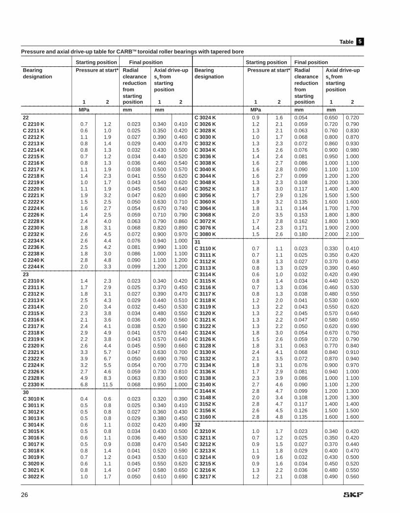
Table
Pressure and axial drive-up table for CARBTM toroidal roller bearings with tapered bore—————————————————————————————————————————————————————————————————————
5
Starting position Final position—————————————————————————————————————————Bearing Pressure at start* Radial Axial drive-up designation clearance ss from
reduction startingfrom positionstarting
1 2 position 1 2—————————————————————————————————————————
MPa mm mm—————————————————————————————————————————22C 2210 K 0.7 1.2 0.023 0.340 0.410C 2211 K 0.6 1.0 0.025 0.350 0.420C 2212 K 1.1 1.9 0.027 0.390 0.460C 2213 K 0.8 1.4 0.029 0.400 0.470C 2214 K 0.8 1.3 0.032 0.430 0.500C 2215 K 0.7 1.2 0.034 0.440 0.520C 2216 K 0.8 1.3 0.036 0.460 0.540C 2217 K 1.1 1.9 0.038 0.500 0.570C 2218 K 1.4 2.3 0.041 0.550 0.620C 2219 K 1.0 1.7 0.043 0.540 0.620C 2220 K 1.1 1.9 0.045 0.560 0.640C 2221 K 1.9 3.2 0.047 0.620 0.690C 2222 K 1.5 2.5 0.050 0.630 0.710C 2224 K 1.6 2.7 0.054 0.670 0.740C 2226 K 1.4 2.5 0.059 0.710 0.790C 2228 K 2.4 4.0 0.063 0.790 0.860C 2230 K 1.8 3.1 0.068 0.820 0.890C 2232 K 2.6 4.5 0.072 0.900 0.970C 2234 K 2.6 4.4 0.076 0.940 1.000C 2236 K 2.5 4.2 0.081 0.990 1.100C 2238 K 1.8 3.0 0.086 1.000 1.100C 2240 K 2.8 4.8 0.090 1.100 1.200C 2244 K 2.0 3.3 0.099 1.200 1.200
—————————————————————————————————————————23C 2310 K 1.4 2.3 0.023 0.340 0.420C 2311 K 1.7 2.9 0.025 0.370 0.450C 2312 K 1.8 3.1 0.027 0.390 0.470C 2313 K 2.5 4.3 0.029 0.440 0.510C 2314 K 2.0 3.4 0.032 0.450 0.530C 2315 K 2.3 3.8 0.034 0.480 0.550C 2316 K 2.1 3.6 0.036 0.490 0.560C 2317 K 2.4 4.1 0.038 0.520 0.590C 2318 K 2.9 4.9 0.041 0.570 0.640C 2319 K 2.2 3.8 0.043 0.570 0.640C 2320 K 2.6 4.4 0.045 0.590 0.660C 2321 K 3.3 5.7 0.047 0.630 0.700C 2322 K 3.9 6.7 0.050 0.690 0.760C 2324 K 3.2 5.5 0.054 0.700 0.770C 2326 K 2.7 4.6 0.059 0.730 0.810C 2328 K 4.9 8.3 0.063 0.830 0.900C 2330 K 6.8 11.5 0.068 0.950 1.000
—————————————————————————————————————————30C 3010 K 0.4 0.6 0.023 0.320 0.390C 3011 K 0.5 0.8 0.025 0.340 0.410C 3012 K 0.5 0.8 0.027 0.360 0.430C 3013 K 0.5 0.8 0.029 0.380 0.450C 3014 K 0.6 1.1 0.032 0.420 0.490C 3015 K 0.5 0.8 0.034 0.430 0.500C 3016 K 0.6 1.1 0.036 0.460 0.530C 3017 K 0.5 0.9 0.038 0.470 0.540C 3018 K 0.8 1.4 0.041 0.520 0.590C 3019 K 0.7 1.2 0.043 0.530 0.610C 3020 K 0.6 1.1 0.045 0.550 0.620C 3021 K 0.8 1.4 0.047 0.580 0.650C 3022 K 1.0 1.7 0.050 0.610 0.690
Starting position Final position—————————————————————————————————————————Bearing Pressure at start* Radial Axial drive-up designation clearance ss from
reduction startingfrom positionstarting
1 2 position 1 2—————————————————————————————————————————
MPa mm mm—————————————————————————————————————————C 3024 K 0.9 1.6 0.054 0.650 0.720C 3026 K 1.2 2.1 0.059 0.720 0.790C 3028 K 1.3 2.1 0.063 0.760 0.830C 3030 K 1.0 1.7 0.068 0.800 0.870C 3032 K 1.3 2.3 0.072 0.860 0.930C 3034 K 1.5 2.6 0.076 0.900 0.980C 3036 K 1.4 2.4 0.081 0.950 1.000C 3038 K 1.6 2.7 0.086 1.000 1.100C 3040 K 1.6 2.8 0.090 1.100 1.100C 3044 K 1.6 2.7 0.099 1.200 1.200C 3048 K 1.3 2.3 0.108 1.200 1.300C 3052 K 1.8 3.0 0.117 1.400 1.400C 3056 K 1.7 2.9 0.126 1.500 1.500C 3060 K 1.9 3.2 0.135 1.600 1.600C 3064 K 1.8 3.1 0.144 1.700 1.700C 3068 K 2.0 3.5 0.153 1.800 1.800C 3072 K 1.7 2.8 0.162 1.800 1.900C 3076 K 1.4 2.3 0.171 1.900 2.000C 3080 K 1.5 2.6 0.180 2.000 2.100
—————————————————————————————————————————31C 3110 K 0.7 1.1 0.023 0.330 0.410C 3111 K 0.7 1.1 0.025 0.350 0.420C 3112 K 0.8 1.3 0.027 0.370 0.450C 3113 K 0.8 1.3 0.029 0.390 0.460C 3114 K 0.6 1.0 0.032 0.420 0.490C 3115 K 0.8 1.4 0.034 0.440 0.520C 3116 K 0.7 1.3 0.036 0.460 0.530C 3117 K 0.8 1.3 0.038 0.480 0.550C 3118 K 1.2 2.0 0.041 0.530 0.600C 3119 K 1.3 2.2 0.043 0.550 0.620C 3120 K 1.3 2.2 0.045 0.570 0.640C 3121 K 1.3 2.2 0.047 0.580 0.650C 3122 K 1.3 2.2 0.050 0.620 0.690C 3124 K 1.8 3.0 0.054 0.670 0.750C 3126 K 1.5 2.6 0.059 0.720 0.790C 3128 K 1.8 3.1 0.063 0.770 0.840C 3130 K 2.4 4.1 0.068 0.840 0.910C 3132 K 2.1 3.5 0.072 0.870 0.940C 3134 K 1.8 3.1 0.076 0.900 0.970C 3136 K 1.7 2.9 0.081 0.940 1.000C 3138 K 2.3 3.9 0.086 1.000 1.100C 3140 K 2.7 4.6 0.090 1.100 1.200C 3144 K 2.8 4.7 0.099 1.200 1.300C 3148 K 2.0 3.4 0.108 1.200 1.300C 3152 K 2.8 4.7 0.117 1.400 1.400C 3156 K 2.6 4.5 0.126 1.500 1.500C 3160 K 2.8 4.8 0.135 1.600 1.600
—————————————————————————————————————————32C 3210 K 1.0 1.7 0.023 0.340 0.420C 3211 K 0.7 1.2 0.025 0.350 0.420C 3212 K 0.9 1.5 0.027 0.370 0.440C 3213 K 1.1 1.8 0.029 0.400 0.470C 3214 K 0.9 1.6 0.032 0.430 0.500C 3215 K 0.9 1.6 0.034 0.450 0.520C 3216 K 1.3 2.2 0.036 0.480 0.550C 3217 K 1.2 2.1 0.038 0.490 0.560

27
Table
Pressure and axial drive-up table for CARBTM toroidal roller bearings with tapered bore—————————————————————————————————————————————————————————————————————
5
Starting position Final position—————————————————————————————————————————Bearing Pressure at start* Radial Axial drive-up designation clearance ss from
reduction startingfrom positionstarting
1 2 position 1 2—————————————————————————————————————————
MPa mm mm—————————————————————————————————————————C 3218 K 1.8 3.1 0.041 0.550 0.620C 3219 K 1.3 2.2 0.043 0.540 0.610C 3220 K 2.1 3.6 0.045 0.590 0.660C 3221 K 2.4 4.1 0.047 0.610 0.690C 3222 K 2.6 4.4 0.050 0.660 0.730C 3224 K 2.5 4.2 0.054 0.680 0.760C 3226 K 2.5 4.3 0.059 0.740 0.810C 3228 K 2.9 5.0 0.063 0.790 0.860C 3230 K 2.3 3.9 0.068 0.820 0.890C 3232 K 2.7 4.6 0.072 0.870 0.940C 3234 K 3.9 6.6 0.076 0.960 1.000C 3236 K 3.7 6.3 0.081 1.000 1.100C 3238 K 2.9 5.0 0.086 1.000 1.100C 3240 K 2.6 4.4 0.090 1.100 1.100
—————————————————————————————————————————40C 4010 K30 0.4 0.8 0.023 0.800 0.990C 4011 K30 0.7 1.2 0.025 0.870 1.100C 4012 K30 0.5 0.9 0.027 0.890 1.100
Starting position Final position—————————————————————————————————————————Bearing Pressure at start* Radial Axial drive-up designation clearance ss from
reduction startingfrom positionstarting
1 2 position 1 2—————————————————————————————————————————
MPa mm mm—————————————————————————————————————————C 4013 K30 0.5 0.9 0.029 0.950 1.100C 4014 K30 0.6 1.1 0.032 1.000 1.200C 4015 K30 0.7 1.3 0.034 1.100 1.300C 4016 K30 0.8 1.4 0.036 1.200 1.300C 4017 K30 0.6 1.2 0.038 1.200 1.400C 4018 K30 0.9 1.7 0.041 1.300 1.500C 4019 K30 0.8 1.5 0.043 1.300 1.500C 4020 K30 0.7 1.3 0.045 1.400 1.600C 4021 K30 1.0 1.9 0.047 1.500 1.600C 4022 K30 0.9 1.6 0.050 1.500 1.700C 4024 K30 0.8 1.5 0.054 1.600 1.800C 4026 K30 1.2 2.2 0.059 1.800 2.000C 4028 K30 1.2 2.3 0.063 1.900 2.100C 4030 K30 1.2 2.2 0.068 2.000 2.200C 4032 K30 1.1 2.0 0.072 2.100 2.300C 4034 K30 1.4 2.5 0.076 2.200 2.400C 4036 K30 1.2 2.2 0.081 2.300 2.500C 4038 K30 1.5 2.8 0.086 2.500 2.700C 4040 K30 1.4 2.5 0.090 2.600 2.800
* = Values given valid for HMV(C) E series nut size = Bearing size1 = Should be applied when one surface slides during mounting. Surface lightly oiled, with light oil.2 = Should be applied when two surfaces slide during mounting. Surface lightly oiled, with light oil.The table is only valid for solid steel shafts. For hollow shafts or other materials please contact SKFFor existing and planned range please contact your local SKF sales company
NOTE: to convert values to inches and psiin = mm/25.4psi = 145 x MPa

28
Guidelines for Bearing Assembly, Maintenance and InspectionFor Better Bearing Performance
Don’t work under the handicap of poor tools, dirt, arough bench, or cluttered area.
Clean tools and surroundings will help maximizebearing performance.
Proper care begins in the stock room. Store bearings in original unopened packages, in a dry place. The bearing number is plainly shown on the box orwrapping. Before packaging, the manufacturer protected the bearing with a rustpreventive slush compound. An unopened package means continued protection.Do not open carton until ready to use.
Open package only when ready to install bearing. Handle bearing with clean,dry hands and with clean rags. Lay bearing on clean paper and keep covered.Never expose bearing on a dirty bench or floor. Never use a bearing as a gaugeto check either the housing bore or the shaft fit.
Don’t wash a new bearing — it is already clean and the slushing oil should notbe removed. Old grease can be washed from a used bearing with a solvent butfluid and container must be clean. After this cleaning, wash the bearing outthoroughly with light oil and then relubricate. Bearings should be washed onlywhen necessary. (See pages 31 and 79).
Before mounting, be sure shaft size is within the specified tolerances recommended for the bearing. The bearing seat should be perfectly roundand not tapered. It should be clean and free from nicks and burrs. If a shaftis too worn to properly seat a bearing — don’t use it! Support shaft firmly ina clean place; if in a vise, protect it from vice jaws. Protectors can be softmetal, wood, cardboard or paper.

29
To press bearing on shaft, first apply a thin coating of lightweight oil to the bearing seat and bore. Place fitting tool over the shaft and rest it on inner ring.Be sure bearing is square on shaft, then apply pressure by tapping fitting tool orend of pipe with hammer or using arbor press.
When temperature mounting an open cylindrical bore bearing, three methodsare typically used:1. Using an induction heater2. Heating in a clean temperature-controlled electric oven or on a hotplate to a
maximum of 121˚C (250˚F) for about 15 minutes. 3. Boiling in emulsion of 10% to 15% soluble oil in water. Be sure to place
supports under bearing to isolate it from bottom of container, as contact willoverheat bearing. Also be sure that oil is clean. (See p. 9).
Thoroughly heat bearing but do not overheat. This will prevent seizing on thecold shaft. After bearing is in place against shaft shoulder, lock it immediatelywith a locknut. Otherwise, in shrinking, bearing may move away from its properposition against shaft shoulder.
DangerWhen mounting in a split housing, check bore of housing to see that it is withinspecified tolerances and is perfectly round. Bearing must not be pinched by asmall bore or because of a cocked outer ring. Don’t switch housing caps — theyare not interchangeable. An undersized housing bore will pinch the bearing andcause early failure.
Some precautions must be taken when mounting bearings in a solid housing;i.e., the outer ring should be perfectly square with the housing bore before anypressure is applied. Here again, the housing bore should be within the specifiedtolerances for the bearing size and should be perfectly round. The housing bore and bearing outside diameter should be coated with a thin coating oflightweight oil.
Cover an unfinished job, even if it is left for only a few hours. Rewrap each bearing with greaseproof paper to keep out dirt and moisture.
The type of lubricant used usually depends on operating conditions — follow themachine builder’s instructions. When oil is used, cover about half of bottom ballor roller. It is preferred that an oil sight gage be used and marked to show staticand operating oil levels. This helps to determine when additional oil is required.The operating level is different from the static level and can be determined onlywhen the bearing is in operation. For more details, see section on lubrication(page 64).

30
Be sure bearing is square with and held firmly against shaft shoulder. Secure itwith a locknut and lockwasher. Housing covers must be tight to keep lubricant inand dirt out. After held bearing has been positioned, the free bearing should belocated centrally in its housing to permit expansion and contraction of the shaft.
Lockwasher Shaft shoulder
Shaft shoulder
Housing cowerdrawn tight
SealLocknut
Gasket
Small and medium-sized bearings may be dismounted cold using a conventional puller. If the bearing has been mounted with an interference fit onthe shaft, the puller should preferably engage the inner ring.
To avoid damage to the bearing seating, the puller must be accurately centered. The use of a 3 jaw or split strong back puller (shown) eliminates therisk of damage, and dismounting is simpler and faster.
One of the easiest mounting and dismounting procedures, the SKF Oil Injectionmethod is frequently used for larger sized bearings.
Bearing pullers may be used separately or in various combinations to pull orpush complete bearings or individual rings.
Never pound directly on a bearing or ring.This may damage both shaft and bearing.WARNING: There is also a danger ofthe bearing shattering and causinghuman injury.
To drive shaft out of bearing, use a softmetal slug which will not mar the shaft(available in SKF Fitting Tool Kit).
An arbor press is equally good for bothcold mounting and removing bearings.

31
Do not spin by force of air. Hold both rings.Use clean, dry air.
Do not spin bearings before cleaning. Dirtcan cause serious scratching.
Soak bearings thoroughly in solvent. Thenrinse them in clean solvent, light oil orkerosene.
Can the Bearing Be Used Again?Always inspect a dismounted bearing,but don’t try to judge whether it can bereused until after it has been cleaned.Treat it as new.
Never spin a dirty bearing; instead,rotate it slowly while washing. Washwith a petroleum-based solvent. Drywith a clean, lint-free cloth or com-pressed clean, moisture-free air, takingcare that no bearing part starts rotating. Contact your SKF AuthorizedDistributor for information on equipment for cleaning and drying.
Larger bearings with badly oxidizedlubricant can be cleaned with a strongalkaline solution, for example, a solu-tion containing up to 10% caustic soda.Add 1% of a suitable wetting agent.
Take care when following this clean-ing procedure: lye is harmful to skin,clothing and aluminum. Always useprotective gloves, goggles and apron.
Examine a used bearing closely todetermine whether it is reusable. Use asmall mirror and a dental-type probewith a rounded point to inspect race-ways, cage and rolling elements.
Be alert for scratches, marks,streaks, cracks, discolorations, mirror-like surfaces and so on. Carefullyrotate the bearing and listen to thesound. An undamaged bearing (i.e.,one that has no marks or other defectsand runs evenly without abnormallylarge radial internal clearance) can beremounted. Before a large bearing isremounted for a critical application, askSKF for examination. The cost of suchinspection may actually save money.
Bearings with a shield or seal onone side should be cleaned, dried,inspected and handled in the sameway as bearings without seals.However, never wash a bearing withseals or shields on both sides. Theyare sealed and lubricated for life andshould be replaced if you suspectbearing or seal damage.
To prevent corrosion, use a rust pre-ventative immediately after cleaning.
Cleaning Bearings
There are two methods of cleaningbearings: hot and cold.
Cold cleaning involves washing thebearing in petroleum based solvents ora similar substance. Always use cleanfluid and tools, using one receptacle forthe first wash and another for the finalrinse. Dry the bearing and grease or oilit immediately after drying. Protect itfrom dirt until mounting.
When hot cleaning, use a thin, cleanoil with a flash point of at least 480˚F(250˚C). Heat the oil to about 250˚F(120˚C). Hot cleaning is generally veryeffective. The residual oil, moreover,provides temporary protection againstrust. See p. 79 for more details aboutcleaning bearings.
WARNING:
Use protective gloves whenever possible. Regular contact with petroleumproducts may cause allergic reactions.Follow the Material Safety Data Sheet(MSDS) safety instructions included withthe solvent you use to clean bearings.
Mounting Used Bearings
Remember: Used bearings should bethoroughly cleaned before mounting,except for bearings with integralshields or seals which should never bewashed — just clean the outer surfaces. Replace the bearing if itappears to be damaged.
If a bearing is very dirty or isencrusted with carbonized lubricant, itis generally not worth cleaning. Mostoften it is more economical to install anew bearing.

32
F7 G7 G6 H9 H8 H7 H6 J7 J6 K6K7 M6 M7 N6
N7 P6P7
JS6JS7H10
f6 g6 g5 h8 h6 h5j5 js5
j6 k5k6 m5
m6n5
n6p6
p7 r6
r7
js6
+
–0
+
–0
Fig 1
Shaft and Housing Fits
If a rolling bearing is to function satisfactorily, both the fit between theinner ring and the shaft, and the fit between the outer ring and the housing,must be suitable for the application.
Suitable Fits
Although a bearing must satisfywidely varying operating conditions,which determine the choice of fit, thetolerances for the bearing itself arestandardized. The desired fits cantherefore be obtained only by selectingthe proper tolerances for the shaftdiameter and the housing bore. Thesystem of limits and fits used by industry for all rolling bearings excepttapers (ISO Standard 286) contains aconsiderable choice of shaft and housing tolerances. When used withstandard bearings, these will give anyof the desired fits, from the tightest tothe loosest required. Each tolerance isdesignated by a letter and a numeral.The letter (small for shaft diametersand capital for housing bores) locatesthe tolerance zone in relation to thenominal dimensions, and the numeralgives the magnitude of the tolerancezone. Figure illustrates this rela-tion. The rectangles indicate the loca-tion and magnitude of the various shaft and housing tolerance zones which are used for rolling bearings, superim-posed on the bore and O.D. tolerance.
The selection of fit depends on thecharacter of the load, the bearingdimensions, the temperature conditions in the bearing in operation,the heat expansion of the shaft andother parts, the design, and therequirements for running accuracy.
1
Consideration must also be given to the fact that a solid shaft deformsdifferently than a hollow one.
In determining suitable fits for theinner ring and the outer ring in anygiven application, the direction of theload in relation to the respective bear-
ing ring is of prime importance. For theselection of the proper shaft and hous-ing tolerance for radial bearings, referto Tables and respectively. Forthrust bearings, see Tables and respectively.
321a1
Figure 1:Location of shaft and housing tolerance grades with respect to bearing bore and O.D. tolerances (exaggerated).

33
perpendicularity tolerance should notexceed the values to IT5. Guidelinevalues for the rectangularity tolerancet2 (and for the total axial runout t4) willbe found in Table .
Surface roughness of bearing seatingsThe roughness of bearing seating sur-faces does not have the same degreeof influence on bearing performanceas the dimensional, form and runningaccuracies. However, a desired inter-ference fit is much more accuratelyobtained the smoother the mating surfaces are. For less critical bearingarrangements relatively large surfaceroughnesses are permitted. For bear-ing arrangements where demands inrespect to accuracy are high, guidelinevalues for the mean surface roughnessRa are given in Table for differentdimensional accuracies of the bearingseatings. These guideline values applyto ground seatings, which are normallyassumed for shaft seatings. For fineturned seatings, the roughness may bea class or two higher.
8
9
Tolerances for cylindrical form
The cylindricity tolerance t, as definedin ISO 1101-1983 should be 1 to 2 ITgrades better than the prescribeddimensional tolerance, depending onrequirements. For example, if a bear-ing seating on a shaft has beenmachined to tolerance m6, then theaccuracy of form should be to IT5 orIT4. The tolerance value t1 for cylin-dricity is obtained for an assumed shaftdiameter of 150 mm from t1 = IT5/2 =18/2 = 9�m or from t1 = IT4/2 = 12/2 =6�m. Table gives guideline valuesfor the cylindrical form tolerance (and for the total runout tolerance t3if preferred).
Tolerance for perpendicularity
Abutments for bearing rings shouldhave a rectangularity tolerance asdefined in ISO 1101-1983 which is better by at least one IT grade than the diameter tolerance of theassociated cylindrical seating. Forthrust bearing washer seatings, the
9
The symbols for the shaft and housingtolerances that apply in each case maybe determined from the tables by takinginto account the conditions of loading,the type and size of the bearing.
For the definitions of “light”, “normal”and “heavy” loads, refer to Figure .For corresponding maximum and mini-mum shaft and housing diameters andthe resulting maximum and minimuminterference of clearance fits, see:Tables and (inch and metric,respectively) for bearing bore andshaft; Tables and (inch andmetric, respectively) for bearing O.D.and housing.
For inch dimensioned tapered rollerbearings, the recommended shaftdiameter and housing bore deviationsfrom nominal diameters and the result-ing fits are shown in Tables – .
Dimensional, form and runningaccuracy of bearing seatings andabutmentsThe accuracy of cylindrical bearingseatings on shafts and in housingbores, of seatings for thrust bearingwashers and of the support surfaces(abutments) for bearing rings providedby shaft and housing shoulders, etc.should correspond to the accuracy ofthe bearings used. In the following,guideline values for dimensional, formand running accuracy are given whichshould be adhered to when machiningseatings and abutments.
Dimensional tolerances
For bearings made with normal tolerances, the dimensional accuracy ofthe cylindrical seatings on the shaft isshown in Tables , , and .For housings, see Tables , ,and . For bearings with higher accu-racy, correspondingly higher tolerancesshould be used; for ABEC 5 bearingssee Tables and .
Where adapter or withdrawalsleeves are used on cylindrical shafts,wider diameter tolerances can be permitted than for bearing seatings;see Table .
The basic tolerance for the standard-ized tolerance series to ISO/R286-1962 will be found in Table .7
4
1514
6b6a31a
5b5a21
1310
6b6a
5b5a
2
20 10 7 5
normalBALLBEARINGS
CYLINDRICALROLLERBEARINGS
SPHERICALROLLERBEARINGS
normal
normal
4 3
C/P
light
light
light
heavy
heavy
heavy
in case ofextremely
heavy loads,C/P < 4,
consult SKF.
Fig 2
Figure 2:Classification of “light, medium, and heavy” loading, expressed in C/P.C = Basic Load Rating as shown in SKF catalogs (as per ABMA Standards 9 and 11,
and modified for improved materials and manufacturing methods).P = Equivalent dynamic bearing load (for definition, see SKF product catalogs).

34
Table
Selection of Solid Steel Shaft Tolerance Classification for Metric Radial Ball and Roller Bearings of Tolerance Classes ABEC-1, RBEC-1(Except Inch Dimensioned Tapered Roller Bearings)
Conditions Shaft diameter, mm ToleranceBall Cylindrical roller Spherical roller Symbolbearings1 bearings, bearings
metric taper
Rotating inner ring load or direction of loading indeterminate
Light loads 18≤100 ≤40 — j6100≤140 40≤100 — k6
Normal loads ≤18 — — j518≤100 ≤40 ≤40 k5 (k6)2
100≤140 40≤100 40≤65 m5 (m6)2
140≤200 100≤140 65≤100 m6200≤280 140≤200 100≤140 n6— 200≤400 140≤280 p6— — 280≤500 r6— — >500 r7
Heavy loads — 50≤140 50≤100 n63
— 140≤200 100≤140 p63
— ≤200 >140 r63
High demands on running ≤18 — — h54
accuracy with light loads 18≤100 ≤40 — j54
100≤200 40≤140 — k54
— 140≤200 — m54
Stationary inner ring load
Easy axial displacement of all all all g6inner ring on shaft desirable
Easy axial displacement of all all all h6inner ring on shaft unnecessary
Axial loads only
≤250 ≤250 ≤250 j6>250 >250 >250 js6
1Shaft tolerances for Y-bearings (set-screw mounted) are available from SKF.2The tolerances in brackets are generally used for metric taper roller and single row angular ball bearings used individually. They can also be used for other types of bear-ing where speeds are moderate and the effect of bearing internal clearance is not significant.
3Bearings with radial internal clearance greater than Normal are necessary.4For ABCE 5 bearings, use Table 14; for higher precision bearings other recommendations apply. Consult SKF.≤ less than or equal to.
1

35
Table
Selection of Steel or Cast Iron Housing Tolerance Classification for Metric Radial Ball and Roller Bearings of Tolerance Classes ABEC-1, RBEC-1(Except Inch Dimensioned Tapered Roller Bearings)
Conditions Tolerance DisplacementSymbol of outer ring
SOLID HOUSINGS
Rotating outer ring load
Heavy loads on bearings in thin-walled P7 Cannot be displacedhousings, heavy shock loads
Normal loads and heavy loads N7 Cannot be displaced
Light and variable loads M7 Cannot be displaced
Direction of load indeterminate
Heavy shock loads M7 Cannot be displaced
Normal loads and heavy loads axial K7 Cannot be displaceddisplacement of outer ring unnecessary as a rule
Accurate or silent running
K61 Cannot be displaced as a rule
J62 Can be displaced
H6 Can easily be displaced
SPLIT OR SOLID HOUSING
Direction of load indeterminate
Light loads and normal loads axial J7 Can be displaceddisplacement of outer ring desirable as a rule
Stationary outer ring load
Loads of all kinds H73 Can easily be displaced
Light loads and normal loads H8 Can easily be displacedwith simple working conditions
Heat conduction through shaft G74 Can easily be displaced
1For heavier loads a tighter fit than K6 should be selected, e.g., M6 or N6. For high precision bearings other recommendations apply. Further details on request.2For ABCE 5 bearings, use Table 15; for higher precision bearings other recommendations apply. Consult SKF.3For large bearings (D >250 mm) and temperature differences between outer ring and housing >10°C (>18°F), G7 may be used instead of H7.4For large bearings (D >250 mm) and temperature differences between outer ring and housing >10°C (>18°F), F7 may be used instead of G7.
1a

36
Table
Selection of Shaft Tolerance for Thrust Bearings
Conditions Shaft diameter, mm Tolerance
Axial loads only
Thrust ball bearings all h6Cylindrical roller thrust bearings all h6
Radial and axial loadson spherical roller thrust bearings
Stationary load on shaft washer ≤250 j6>250 js6
Rotating load on shaft washer <200 k6or direction of loading indeterminate 200≤400 m6
>400 n6> greater than.≤ less than or equal to.
2
Table
Selection of Housing Tolerances for Thrust Bearings
Conditions Tolerance Remarks
Axial loads only
Thrust ball bearings H8 For less accurate bearing arrangementsthere can be radial clearance of up to 0.001 D
Cylindrical roller thrust bearings H7
Cylindrical roller and cage thrust assemblies H10
Spherical roller thrust bearings, where — Housing washer fitted with radialanother bearing is used for radial location clearance of up to 0.001 D. Consult SKF.
3
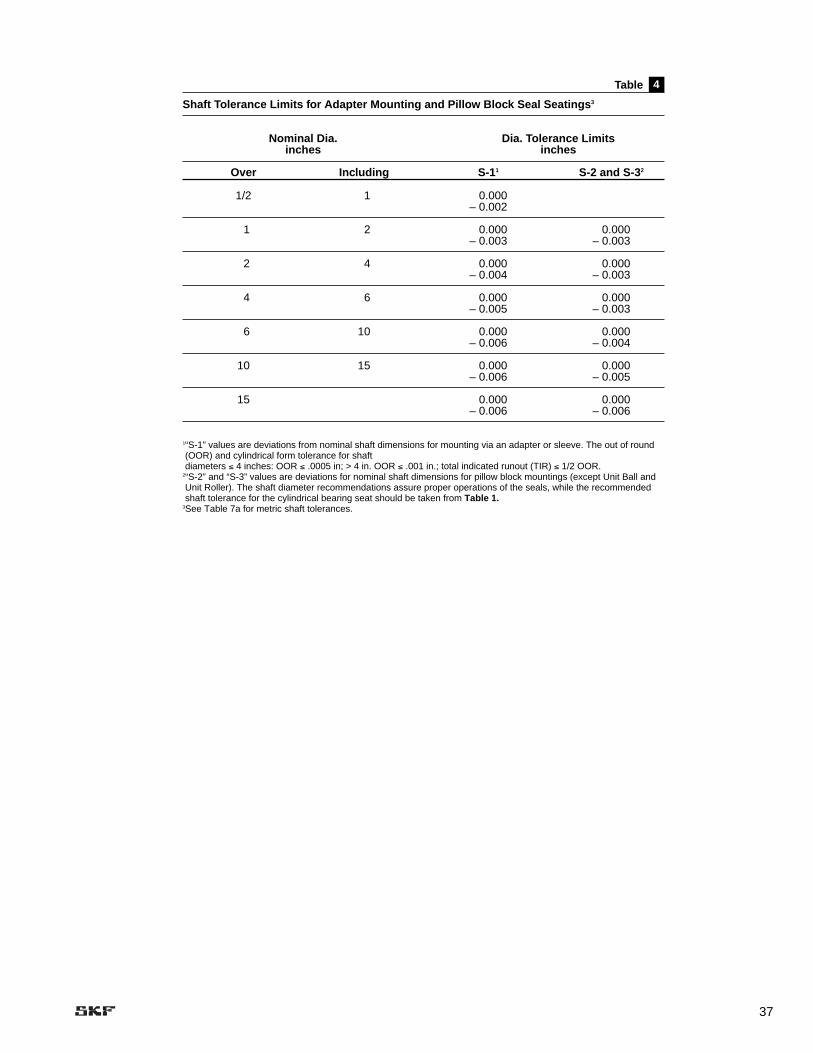
37
Table
Shaft Tolerance Limits for Adapter Mounting and Pillow Block Seal Seatings3
Nominal Dia. Dia. Tolerance Limitsinches inches
Over Including S-11 S-2 and S-32
1/2 1 0.000– 0.002
1 2 0.000 0.000– 0.003 – 0.003
2 4 0.000 0.000– 0.004 – 0.003
4 6 0.000 0.000– 0.005 – 0.003
6 10 0.000 0.000– 0.006 – 0.004
10 15 0.000 0.000– 0.006 – 0.005
15 0.000 0.000– 0.006 – 0.006
1“S-1” values are deviations from nominal shaft dimensions for mounting via an adapter or sleeve. The out of round(OOR) and cylindrical form tolerance for shaft diameters ≤ 4 inches: OOR ≤ .0005 in; > 4 in. OOR ≤ .001 in.; total indicated runout (TIR) ≤ 1/2 OOR.
2“S-2” and “S-3” values are deviations for nominal shaft dimensions for pillow block mountings (except Unit Ball andUnit Roller). The shaft diameter recommendations assure proper operations of the seals, while the recommendedshaft tolerance for the cylindrical bearing seat should be taken from Table 1.
3See Table 7a for metric shaft tolerances.
4

38
INCH Table
Shaft Bearing-Seat Diameters (Values in inches)Bearing Bore f7 g6 h6 h5 j5Diameters (inches) Fit Fit Fit Fit Fit
Shaft Dia. in Shaft Dia. in Shaft Dia. in Shaft Dia. in Shaft Dia. in(mm) Max. Min. Max. Min. 0.0000" Max. Min. 0.0000" Max. Min. 0.0000" Max. Min. 0.0000" Max. Min. 0.0000"
4 0.1575 0.1572 0.1571 0.1566 0.1573 0.1570 0.1575 0.1572 0.1575 0.1573 0.1576 0.15745 0.1969 0.1966 0.1965 0.1960 9 L 0.1967 0.1964 5 L 0.1969 0.1966 3 L 0.1969 0.1967 2 L 0.1970 0.1968 1 L6 0.2362 0.2359 0.2358 0.2353 1 L 0.2360 0.2357 1 T 0.2362 0.2359 3 T 0.2362 0.2360 3 T 0.2363 0.2361 4 T7 0.2756 0.2753 0.2751 0.2745 0.2754 0.2750 0.2756 0.2752 0.2756 0.2754 0.2758 0.27558 0.3150 0.3147 0.3145 0.3139 11 L 0.3148 0.3144 6 L 0.3150 0.3146 4 L 0.3150 0.3148 2 L 0.3152 0.3149 1 L9 0.3543 0.3540 0.3538 0.3532 2 L 0.3541 0.3538 1 T 0.3543 0.3539 3 T 0.3543 0.3541 3 T 0.3545 0.3542 5 T
10 0.3937 0.3934 0.3932 0.3926 0.3935 0.3931 0.3937 0.3933 0.3937 0.3935 0.3939 0.393612 0.4724 0.4721 0.4718 0.4711 0.4722 0.4717 0.4724 0.4720 0.4724 0.4721 0.4726 0.472315 0.5906 0.5903 0.5900 0.5893 13 L 0.5904 0.5899 7 L 0.5906 0.5902 4 L 0.5906 0.5903 3 L 0.5908 0.5905 1 L17 0.6693 0.6690 0.6687 0.6680 3 L 0.6691 0.6686 1 T 0.6693 0.6689 3 T 0.6693 0.6690 3 T 0.6695 0.6692 5 T20 0.7874 0.7870 0.7866 0.7858 0.7871 0.7866 0.7874 0.7869 0.7874 0.7870 0.7876 0.787225 0.9843 0.9839 0.9835 0.9827 16 L 0.9840 0.9835 8 L 0.9843 0.9838 5 L 0.9843 0.9839 4 L 0.9845 0.9841 2 L30 1.1811 1.1807 1.1803 1.1795 4 L 1.1808 1.1803 1 T 1.1811 1.1806 4 T 1.1811 1.1807 4 T 1.1813 1.1809 6 T35 1.3780 1.3775 1.3770 1.3760 1.3776 1.3770 1.3780 1.3774 1.3780 1.3776 1.3782 1.377840 1.5748 1.5743 1.5738 1.5728 20 L 1.5744 1.5738 10 L 1.5748 1.5742 6 L 1.5748 1.5744 4 L 1.5750 1.5746 2 L45 1.7717 1.7712 1.7707 1.7697 5 L 1.7713 1.7707 1 T 1.7717 1.7711 5 T 1.7717 1.7713 5 T 1.7719 1.7716 7 T50 1.9685 1.9680 1.9675 1.9665 1.9681 1.9675 1.9685 1.9679 1.9685 1.9681 1.9687 1.968355 2.1654 2.1648 2.1642 2.1630 2.1650 2.1643 2.1654 2.1647 2.1654 2.1649 2.1656 2.165160 2.3622 2.3616 2.3610 2.3598 2.3618 2.3611 2.3622 2.3615 2.3622 2.3617 2.3624 2.361965 2.5591 2.5585 2.5579 2.5567 24 L 2.5587 2.5580 11 L 2.5591 2.5584 7 L 2.5591 2.5586 5 L 2.5593 2.5588 3 L70 2.7559 2.7553 2.7547 2.7535 6 L 2.7555 2.7548 2 T 2.7559 2.7552 6 T 2.7559 2.7554 6 T 2.7561 2.7556 8 T75 2.9528 2.9522 2.9516 2.9504 2.9524 2.9517 2.9528 2.9521 2.9528 2.9523 2.9530 2.952580 3.1496 3.1490 3.1484 3.1472 3.1492 3.1485 3.1496 3.1489 3.1496 3.1491 3.1498 3.149385 3.3465 3.3457 3.3451 3.3437 3.3460 3.3452 3.3465 3.3456 3.3465 3.3459 3.3467 3.346190 3.5433 3.5425 3.5419 3.5405 3.5428 3.5420 3.5433 3.5424 3.5433 3.5427 3.5435 3.542995 3.7402 3.7394 3.7388 3.7374 3.7397 3.7389 3.7402 3.7393 3.7402 3.7396 3.7404 3.7398100 3.9370 3.9362 3.9356 3.9342 28 T 3.9365 3.9357 13 L 3.9370 3.9361 9 L 3.9370 3.9364 6 L 3.9372 3.9366 4 L105 4.1339 4.1331 4.1325 4.1311 6 L 4.1334 4.1326 3 T 4.1339 4.1330 8 T 4.1339 4.1333 8 T 4.1341 4.1335 10 T110 4.3307 4.3299 4.3293 4.3279 4.3302 4.3294 4.3307 4.3298 4.3307 4.3301 4.3309 4.3303115 4.5276 4.5268 4.5262 4.5248 4.5271 4.5263 4.5276 4.5267 4.5276 4.5270 4.5278 4.5272120 4.7244 4.7236 4.7230 4.7216 4.7239 4.7231 4.7244 4.7235 4.7244 4.7238 4.7246 4.7240125 4.9213 4.9203 4.9196 4.9180 4.9207 4.9197 4.9213 4.9203 4.9213 4.9206 4.9216 4.9209130 5.1181 5.1171 5.1164 5.1148 5.1175 5.1166 5.1181 5.1171 5.1181 5.1174 5.1184 5.1177140 5.5118 5.5108 5.5101 5.5085 5.5112 5.5103 5.5118 5.5108 5.5118 5.5111 5.5121 5.5114150 5.9055 5.9045 5.9038 5.9022 33 L 5.9049 5.9040 15 L 5.9055 5.9045 10 L 5.9055 5.9048 7 L 5.9058 5.9051 4 L160 6.2992 6.2982 6.2975 6.2959 7 L 6.2986 6.2977 4 T 6.2992 6.2982 10 T 6.2992 6.2985 10 T 6.2995 6.2988 13 T170 6.6929 6.6919 6.6912 6.6896 6.6923 6.6914 6.6929 6.6919 6.6929 6.6922 6.6932 6.6925180 7.0866 7.0856 7.0849 7.0833 7.0860 7.0851 7.0866 7.0856 7.0866 7.0859 7.0869 7.0862190 7.4803 7.4791 7.4783 7.4765 7.4797 7.4786 7.4803 7.4792 7.4803 7.4795 7.4806 7.4798200 7.8740 7.8728 7.8720 7.8702 38 L 7.8734 7.8723 17 L 7.8740 7.8729 11 L 7.8740 7.8732 8 L 7.8743 7.8735 5 L220 8.6614 8.6602 8.6594 8.6576 8 L 8.6608 8.6597 6 T 8.6614 8.6603 12 T 8.6614 8.6606 12 T 8.6617 8.6609 15 T240 9.4488 9.4476 9.4468 9.4450 9.4482 9.4471 9.4488 9.4477 9.4488 9.4480 9.4491 9.4483250 9.8425 9.8413 9.8405 9.8387 9.8419 9.8408 9.8425 9.8414 9.8425 9.8417 9.8428 9.8420260 10.2362 10.2348 10.2340 10.2319 10.2355 10.2343 10.2362 10.2349 10.2362 10.2353 10.2365 10.2356280 11.0236 11.0222 11.0214 11.0193 43 L 11.0229 11.0217 19 L 11.0236 11.0223 13 L 11.0236 11.0227 9 L 11.0239 11.0230 6 L300 11.8110 11.8096 11.8088 11.8067 8 L 11.8103 11.8091 7 T 11.8110 11.8097 14 T 11.8110 11.8101 14 T 11.8113 11.8104 17 T310 12.2047 12.2033 12.2025 12.2004 12.2040 12.2028 12.2047 12.2034 12.2047 12.2038 12.2050 12.2041320 12.5984 12.5968 12.5959 12.5937 12.5977 12.5963 12.5984 12.5970 12.5984 12.5974 12.5987 12.5977340 13.3858 13.3842 13.3833 13.3811 13.3851 13.3837 13.3858 13.3844 13.3858 13.3848 13.3861 13.3851350 13.7795 13.7779 13.7770 13.7748 47 L 13.7788 13.7774 21 L 13.7795 13.7781 14 L 13.7794 13.7785 10 L 13.7798 13.7788 7 L360 14.1732 14.1716 14.1707 14.1685 9 L 14.1725 14.1711 9 T 14.1732 14.1718 16 T 14.1732 14.1722 16 T 14.1735 14.1725 19 T380 14.9606 14.9590 14.9581 14.9559 14.9599 14.9585 14.9606 14.9592 14.9606 14.9596 14.9609 14.9599400 15.7480 15.7464 15.7455 15.7433 15.7473 15.7459 15.7480 15.7466 15.7480 15.7470 15.7483 15.7473420 16.5354 16.5336 16.5327 16.5302 16.5346 16.5330 16.5354 16.5338 16.5354 16.5343 16.5357 16.5346440 17.3228 17.3210 17.3201 17.3176 52 L 17.3220 17.3204 24 L 17.3228 17.3212 16 L 17.3228 17.3217 11 L 17.3231 17.3220 8 L460 18.1102 18.1084 18.1075 18.1050 9 L 18.1094 18.1078 10 T 18.1102 18.1086 18 T 18.1102 18.1091 18 T 18.1105 18.1094 21 T480 18.8976 18.8958 18.8949 18.8924 18.8968 18.8952 18.8976 18.8960 18.8976 18.8965 18.8979 18.8968500 19.6850 19.6832 19.6823 19.6798 19.6842 19.6826 19.6850 19.6834 19.6850 19.6839 19.6853 19.6842530 20.8661 20.8641 20.8631 20.8605 20.8652 20.8635 20.8661 20.8644560 22.0472 22.0452 22.0442 22.0416 56 L 22.0463 22.0446 26 L 22.0472 22.0455 17 L600 23.6220 23.6200 23.6190 23.6164 10 L 23.6211 23.6194 11 T 23.6220 23.6203 20 T630 24.8031 24.8011 24.8001 24.7975 24.8022 24.8005 24.8031 24.8014660 25.9843 25.9813 25.9811 25.9782 25.9834 25.9814 25.9843 25.9823670 26.3780 26.3750 26.3748 26.3719 26.3771 26.3751 26.3780 26.3760710 27.9528 27.9498 27.9496 27.9467 61 L 27.9519 27.9499 29 L 27.9528 27.9508 20 L750 29.5276 29.5246 29.5244 29.5215 2 L 29.5267 29.5247 21 T 29.5276 29.5256 30 T780 30.7087 30.7057 30.7055 30.7026 30.7078 30.7058 30.7087 30.7067800 31.4961 31.4931 31.4929 31.4900 31.4952 31.4932 31.4962 31.4941850 33.4646 33.4607 33.4611 33.4577 33.4636 33.4614 33.4645 33.4624900 35.4331 35.4292 35.4296 35.4262 69 L 35.4321 35.4299 32 L 35.4331 35.4309 22 L950 37.4016 37.3977 37.3981 37.3947 4 T 37.4006 37.3984 29 T 37.4016 37.3994 39 T1000 39.3701 39.3662 39.3666 39.3632 39.3691 39.3669 39.3701 39.36791060 41.7323 41.7274 41.7284 41.7247 41.7312 41.7286 41.7323 41.72971120 44.0945 44.0896 44.0906 44.0869 76 L 44.0934 44.0908 37 L 44.0945 44.0919 26 L1180 46.4567 46.4518 46.4528 46.4491 10 T 46.4556 46.4530 38 T 46.4567 46.4541 49 T1250 49.2126 49.2077 49.2087 49.2050 49.2115 49.2089 49.2126 49.2100
5a
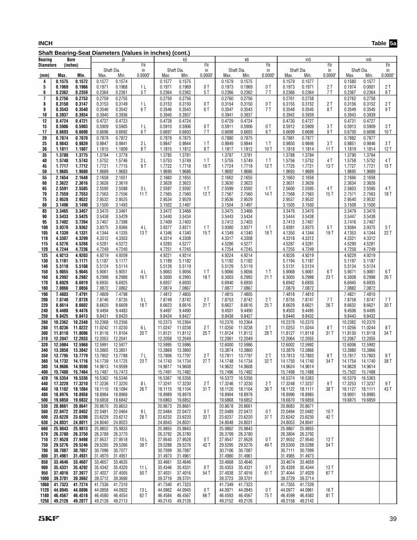
39
INCH Table
Shaft Bearing-Seat Diameters (Values in inches) (cont.)Bearing Bore j6 k5 k6 m5 m6Diameters (inches) Fit Fit Fit Fit Fit
Shaft Dia. in Shaft Dia. in Shaft Dia. in Shaft Dia. in Shaft Dia. in(mm) Max. Min. Max. Min. 0.0000" Max. Min. 0.0000" Max. Min. 0.0000" Max. Min. 0.0000" Max. Min. 0.0000"
4 0.1575 0.1572 0.1577 0.1574 0.1577 0.1575 0.1579 0.1575 0.1579 0.1577 0.1580 0.15775 0.1969 0.1966 0.1971 0.1968 1 L 0.1971 0.1969 0 T 0.1973 0.1969 0 T 0.1973 0.1971 2 T 0.1974 0.0001 2 T6 0.2362 0.2359 0.2364 0.2361 5 T 0.2364 0.2362 5 T 0.2366 0.2362 7 T 0.2366 0.2364 7 T 0.2367 0.2364 8 T7 0.2756 0.2753 0.2759 0.2755 0.2759 0.2756 0.2760 0.2756 0.2761 0.2758 0.2762 0.27588 0.3150 0.3147 0.3153 0.3149 1 L 0.3153 0.3150 0 T 0.3154 0.3150 0 T 0.3155 0.3152 2 T 0.3156 0.3152 2 T9 0.3543 0.3540 0.3546 0.3542 6 T 0.3546 0.3543 6 T 0.3547 0.3543 7 T 0.3548 0.3545 8 T 0.3549 0.3545 9 T
10 0.3937 0.3934 0.3940 0.3936 0.3940 0.3937 0.3941 0.3937 0.3942 0.3939 0.3943 0.393912 0.4724 0.4721 0.4727 0.4723 0.4728 0.4724 0.4729 0.4724 0.4730 0.4727 0.4731 0.472715 0.5906 0.5903 0.5909 0.5905 1 L 0.5910 0.5906 0 T 0.5911 0.5906 0 T 0.5912 0.5909 3 T 0.5913 0.5909 3 T17 0.6693 0.6690 0.6696 0.6692 6 T 0.6697 0.6693 7 T 0.6698 0.6693 8 T 0.6699 0.6696 9 T 0.6700 0.6696 10 T20 0.7874 0.7870 0.7878 0.7872 0.7878 0.7875 0.7880 0.7875 0.7881 0.7877 0.7882 0.787725 0.9843 0.9839 0.9847 0.9841 2 L 0.9847 0.9844 1 T 0.9849 0.9844 1 T 0.9850 0.9846 3 T 0.9851 0.9846 3 T30 1.1811 1.1807 1.1815 1.1809 8 T 1.1815 1.1812 8 T 1.1817 1.1812 10 T 1.1818 1.1814 11 T 1.1819 1.1814 12 T35 1.3780 1.3775 1.3784 1.3778 1.3785 1.3781 1.3787 1.3781 1.3788 1.3784 1.3790 1.378440 1.5748 1.5743 1.5752 1.5746 2 L 1.5753 1.5749 1 T 1.5755 1.5749 1 T 1.5756 1.5752 4 T 1.5758 1.5752 4 T45 1.7717 1.7712 1.7721 1.7715 9 T 1.7722 1.7718 10 T 1.7724 1.7718 12 T 1.7725 1.7721 13 T 1.7727 1.7721 15 T50 1.9685 1.9680 1.9689 1.9683 1.9690 1.9686 1.9692 1.9686 1.9693 1.9689 1.9695 1.968955 2.1654 2.1648 2.1658 2.1651 2.1660 2.1655 2.1662 2.1655 2.1663 2.1658 2.1666 2.165860 2.3622 2.3616 2.3626 2.3619 2.3628 2.3623 2.3630 2.3623 2.3631 2.3626 2.3634 2.362665 2.5591 2.5585 2.5595 2.5588 3 L 2.5597 2.5592 1 T 2.5599 2.5592 1 T 2.5600 2.5595 4 T 2.5603 2.5595 4 T70 2.7559 2.7553 2.7563 2.7556 11 T 2.7565 2.7560 12 T 2.7567 2.7560 14 T 2.7568 2.7563 15 T 2.7571 2.7563 18 T75 2.9528 2.9522 2.9532 2.9525 2.9534 2.9529 2.9536 2.9529 2.9537 2.9532 2.9540 2.953280 3.1496 3.1490 3.1500 3.1493 3.1502 3.1497 3.1504 3.1497 3.1505 3.1500 3.1508 3.150085 3.3465 3.3457 3.3470 3.3461 3.3472 3.3466 3.3475 3.3466 3.3476 3.3470 3.3479 3.347090 3.5433 3.5425 3.5438 3.5429 3.5440 3.5434 3.5443 3.5434 3.5444 3.5438 3.5447 3.543895 3.7402 3.7394 3.7407 3.7398 3.7409 3.7403 3.7412 3.7403 3.7413 3.7407 3.7416 3.7407100 3.9370 3.9362 3.9375 3.9366 4 L 3.9377 3.9371 1 T 3.9380 3.9371 1 T 3.9381 3.9375 5 T 3.9384 3.9375 5 T105 4.1339 4.1331 4.1344 4.1335 13 T 4.1346 4.1340 15 T 4.1349 4.1340 18 T 4.1350 4.1344 19 T 4.1353 4.1344 22 T110 4.3307 4.3299 4.3312 4.3303 4.3314 4.3308 4.3317 4.3308 4.3318 4.3312 4.3321 4.3312115 4.5276 4.5268 4.5281 4.5272 4.5283 4.5277 4.5286 4.5277 4.5287 4.5281 4.5290 4.5281120 4.7244 4.7236 4.7249 4.7240 4.7251 4.7245 4.7254 4.7245 4.7255 4.7249 4.7258 4.7249125 4.9213 4.9203 4.9219 4.9209 4.9221 4.9214 4.9224 4.9214 4.9226 4.9219 4.9229 4.9219130 5.1181 5.1171 5.1187 5.1177 5.1189 5.1182 5.1192 5.1182 5.1194 5.1187 5.1197 5.1187140 5.5118 5.5108 5.5124 5.5114 5.5126 5.5119 5.5129 5.5119 5.5131 5.5124 5.5134 5.5124150 5.9055 5.9045 5.9061 5.9051 4 L 5.9063 5.9056 1 T 5.9066 5.9056 1 T 5.9068 5.9061 6 T 5.9071 5.9061 6 T160 6.2992 6.2982 6.2998 6.2988 16 T 6.3000 6.2993 18 T 6.3003 6.2993 21 T 6.3005 6.2998 23 T 6.3008 6.2998 26 T170 6.6929 6.6919 6.6935 6.6925 6.6937 6.6930 6.6940 6.6930 6.6942 6.6935 6.6945 6.6935180 7.0866 7.0856 7.0872 7.0862 7.0874 7.0867 7.0877 7.0867 7.0879 7.0872 7.0882 7.0872190 7.4803 7.4791 7.4809 7.4798 7.4812 7.4805 7.4815 7.4805 7.4818 7.4810 7.4821 7.4810200 7.8740 7.8728 7.8746 7.8735 5 L 7.8749 7.8742 2 T 7.8753 7.8742 2 T 7.8755 7.8747 7 T 7.8758 7.8747 7 T220 8.6614 8.6602 8.6620 8.6609 18 T 8.6623 8.6616 21 T 8.6627 8.6616 25 T 8.6629 8.6621 26 T 8.6632 8.6621 30 T240 9.4488 9.4476 9.4494 9.4483 9.4497 9.4490 9.4501 9.4490 9.4503 9.4495 9.4506 9.4495250 9.8425 9.8413 9.8431 9.8420 9.8434 9.8427 9.8438 9.8427 9.8440 9.8432 9.8443 9.8432260 10.2362 10.2348 10.2368 10.2356 10.2373 10.2364 10.2376 10.2364 10.2379 10.2370 10.2382 10.2370280 11.0236 11.0222 11.0242 11.0230 6 L 11.0247 11.0238 2 T 11.0250 11.0238 2 T 11.0253 11.0244 8 T 11.0256 11.0244 8 T300 11.8110 11.8096 11.8116 11.8104 20 T 11.8121 11.8112 25 T 11.8124 11.8112 28 T 11.8127 11.8118 31 T 11.8130 11.8118 34 T310 12.2047 12.2033 12.2053 12.2041 12.2058 12.2049 12.2061 12.2049 12.2064 12.2055 12.2067 12.2055320 12.5984 12.5968 12.5991 12.5977 12.5995 12.5986 12.6000 12.5986 12.6002 12.5992 12.6006 12.5992340 13.3858 13.3842 13.3865 13.3851 13.3869 13.3860 13.3874 13.3860 13.3876 13.3866 13.3880 13.3866350 13.7795 13.7779 13.7802 13.7788 7 L 13.7806 13.7797 2 T 13.7811 13.7797 2 T 13.7813 13.7803 8 T 13.7817 13.7803 8 T360 14.1732 14.1716 14.1739 14.1725 23 T 14.1743 14.1734 27 T 14.1748 14.1734 32 T 14.1750 14.1740 34 T 14.1754 14.1740 38 T380 14.9606 14.9590 14.9613 14.9599 14.9617 14.9608 14.9622 14.9608 14.9624 14.9614 14.9628 14.9614400 15.7480 15.7464 15.7487 15.7473 15.7491 15.7482 15.7496 15.7482 15.7498 15.7488 15.7502 15.7488420 16.5354 16.5336 16.5362 16.5346 16.5367 16.5356 16.5372 16.5356 16.5374 16.5363 16.5379 16.5363440 17.3228 17.3210 17.3236 17.3220 8 L 17.3241 17.3230 2 T 17.3246 17.3230 2 T 17.3248 17.3237 9 T 17.3253 17.3237 9 T460 18.1102 18.1084 18.1110 18.1094 26 T 18.1115 18.1104 31 T 18.1120 18.1104 36 T 18.1122 18.1111 38 T 18.1127 18.1111 43 T480 18.8976 18.8958 18.8984 18.8968 18.8989 18.8978 18.8994 18.8978 18.8996 18.8985 18.9001 18.8985500 19.6850 19.6832 19.6858 19.6842 19.6863 19.6852 19.6868 19.6852 19.6870 19.6859 19.6875 19.6859530 20.8661 20.8641 20.8670 20.8653 20.8673 20.8661 20.8678 20.8661 20.8683 20.8671560 22.0472 22.0452 22.0481 22.0464 9 L 22.0484 22.0472 0 T 22.0489 22.0472 0 T 22.0494 22.0482 10 T600 23.6220 23.6200 23.6229 23.6212 28 T 23.6232 23.6220 32 T 23.6237 23.6220 37 T 23.6242 23.6230 42 T630 24.8031 24.8011 24.8040 24.8023 24.8043 24.8031 24.8048 24.8031 24.8053 24.8041660 25.9843 25.9813 25.9852 25.9833 25.9855 25.9843 25.9862 25.9843 25.9867 25.9855670 26.3780 26.3750 26.3789 26.3770 26.3792 26.3780 26.3799 26.3780 26.3804 26.3792710 27.9528 27.9498 27.9537 27.9518 10 L 27.9540 27.9528 0 T 27.9547 27.9528 0 T 27.9552 27.9540 12 T750 29.5276 29.5246 29.5285 29.5266 39 T 29.5288 29.5276 42 T 29.5295 29.5276 49 T 29.5300 29.5288 54 T780 30.7087 30.7057 30.7096 30.7077 30.7099 30.7087 30.7106 30.7087 30.7111 30.7099800 31.4961 31.4931 31.4970 31.4951 31.4973 31.4961 31.4980 31.4961 31.4985 31.4973850 33.4646 33.4607 33.4657 33.4635 33.4661 33.4646 33.4668 33.4646 33.4674 33.4659900 35.4331 35.4292 35.4342 35.4320 11 L 35.4346 35.4331 0 T 35.4353 35.4331 0 T 35.4359 35.4344 13 T950 37.4016 37.3977 37.4027 37.4005 50 T 37.4031 37.4016 54 T 37.4038 37.4016 61 T 37.4044 37.4029 67 T1000 39.3701 39.3662 39.3712 39.3690 39.3716 39.3701 39.3723 39.3701 39.3729 39.37141060 41.7323 41.7274 41.7336 41.7310 41.7340 41.7323 41.7349 41.7323 41.7355 41.73391120 44.0945 44.0896 44.0958 44.0932 13 L 44.0962 44.0945 0 T 44.0971 44.0945 0 T 44.0977 44.0961 16 T1180 46.4567 46.4518 46.4580 46.4554 62 T 46.4584 46.4567 66 T 46.4593 46.4567 75 T 46.4599 46.4583 81 T1250 49.2126 49.2077 49.2139 49.2113 49.2143 49.2126 49.2152 49.2126 49.2158 49.2142
5a

40
INCH Table
Shaft Bearing-Seat Diameters (Values in inches) (cont.)Bearing Bore n6 p6 r6 r7Diameters (inches) Fit Fit Fit Fit
Shaft Dia. in Shaft Dia. in Shaft Dia. in Shaft Dia. in(mm) Max. Min. Max. Min. 0.0000" Max. Min. 0.0000" Max. Min. 0.0000" Max. Min. 0.0000"
4 0.1575 0.1572 0.1581 0.15785 0.1969 0.1966 0.1975 0.1972 3 T6 0.2362 0.2359 0.2368 0.2365 9 T7 0.2756 0.2753 0.2763 0.27608 0.3150 0.3147 0.3157 0.3154 4 T9 0.3543 0.3540 0.3550 0.3547 10 T10 0.3937 0.3934 0.3944 0.394112 0.4724 0.4721 0.4733 0.472915 0.5906 0.5903 0.5915 0.5911 5 T17 0.6693 0.6690 0.6702 0.6698 12 T20 0.7874 0.7870 0.7885 0.788025 0.9843 0.9839 0.9854 0.9849 6 T30 1.1811 1.1807 1.1822 1.1817 15 T35 1.3780 1.3775 1.3793 1.378740 1.5748 1.5743 1.5761 1.5755 7 T45 1.7717 1.7712 1.7730 1.7724 18 T50 1.9685 1.9680 1.9698 1.969255 2.1654 2.1648 2.1669 2.166260 2.3622 2.3616 2.3637 2.363065 2.5591 2.5585 2.5606 2.5599 8 T70 2.7559 2.7553 2.7574 2.7567 21 T75 2.9528 2.9522 2.9543 2.953680 3.1496 3.1490 3.1511 3.150485 3.3465 3.3457 3.3483 3.3474 3.3488 3.348090 3.5433 3.5425 3.5451 3.5442 3.5456 3.544895 3.7402 3.7394 3.7420 3.7411 3.7425 3.7417
100 3.9370 3.9362 3.9388 3.9379 9 T 3.9393 3.9385 15 T105 4.1339 4.1331 4.1357 4.1348 26 T 4.1362 4.1354 31 T110 4.3307 4.3299 4.3325 4.3316 4.3330 4.3322115 4.5276 4.5268 4.5294 4.5285 4.5299 4.5291120 4.7244 4.7236 4.7262 4.7253 4.7267 4.7259125 4.9213 4.9203 4.9233 4.9224 4.9240 4.9230 4.9248 4.9239130 5.1181 5.1171 5.1201 5.1192 5.1208 5.1198 5.1216 5.1207140 5.5118 5.5108 5.5138 5.5129 5.5145 5.5135 5.5153 5.5144150 5.9055 5.9045 5.9075 5.9066 11 T 5.9082 5.9072 17 T 5.9090 5.9081 26 T160 6.2992 6.2982 6.3012 6.3003 30 T 6.3019 6.3009 37 T 6.3027 6.3018 45 T170 6.6929 6.6919 6.6949 6.6940 6.6956 6.6946 6.6964 6.6955180 7.0866 7.0856 7.0886 7.0877 7.0893 7.0883 7.0901 7.0892190 7.4803 7.4791 7.4827 7.4815 7.4834 7.4823 7.4845 7.4833 30 T200 7.8740 7.8728 7.8764 7.8752 12 T 7.8771 7.8760 20 T 7.8782 7.8770 54 T220 8.6614 8.6602 8.6638 8.6626 35 T 8.6645 8.6634 43 T 8.6657 8.6645 31/55 T/T 8.6664 8.6645 31/62 T/T240 9.4488 9.4476 9.4512 9.4500 9.4519 9.4508 9.4532 9.4521 33 T 9.4539 9.4521 33 T250 9.8425 9.8413 9.8449 9.8437 9.8456 9.8445 9.8469 9.8458 56 T 9.8476 9.8458 63 T260 10.2362 10.2348 10.2388 10.2375 10.2397 10.2384 10.2411 10.2399 37 T 10.2419 10.2399 37 T280 11.0236 11.0222 11.0262 11.0249 13 T 11.0271 11.0258 22 T 11.0285 11.0273 63 T 11.0293 11.0273 71 T300 11.8110 11.8096 11.8136 11.8123 40 T 11.8145 11.8132 48 T 11.8161 11.8149 39 T 11.8169 11.8149 39 T310 12.2047 12.2033 12.2073 12.2060 12.2082 12.2069 12.2098 12.2086 65 T 12.2106 12.2086 73 T320 12.5984 12.5968 12.6013 12.5999 12.6023 12.6009 12.6040 12.6027 43 T 12.6049 12.6027 43 T340 13.3858 13.3842 13.3887 13.3873 13.3897 13.3882 13.3914 13.3901 72 T 13.3923 13.3901 81 T350 13.7795 13.7779 13.7824 13.7810 15 T 13.7834 13.7819 24 T 13.7851 13.7838 13.7860 13.7838360 14.1732 14.1716 14.1761 14.1747 45 T 14.1771 14.1756 55 T 14.1791 14.1777 45 T 14.1799 14.1777 45 T380 14.9606 14.9590 14.9635 14.9621 14.9645 14.9631 14.9665 14.9651 75 T 14.9673 14.9651 83 T400 15.7480 15.7464 15.7509 15.7495 15.7519 15.7504 15.7539 15.7525 15.7547 15.7525420 16.5354 16.5336 16.5385 16.5370 16.5397 16.5381 16.5419 16.5404 50 T 16.5428 16.5404 50 T440 17.3228 17.3210 17.3259 17.3244 16 T 17.3271 17.3255 27 T 17.3293 17.3278 83 T 17.3302 17.3278 92 T460 18.1102 18.1084 18.1133 18.1118 49 T 18.1145 18.1129 61 T 18.1170 18.1154 52 T 18.1179 18.1154 52 T480 18.8976 18.8958 18.9007 18.8992 18.9019 18.9003 18.9044 18.9028 86 T 18.9053 18.9028 95 T500 19.6850 19.6832 19.6881 19.6866 19.6893 19.6877 19.6918 19.6902 19.6927 19.6902530 20.8661 20.8641 20.8696 20.8678 20.8709 20.8692 20.8737 20.8720 59 T 20.8748 20.8720 59 T560 22.0472 22.0452 22.0507 22.0489 17 T 22.0520 22.0503 31 T 22.0548 22.0531 96 T 22.0559 22.0531 107 T600 23.6220 23.6200 23.6255 23.6237 55 T 23.6268 23.6251 68 T 23.6298 23.6281 61 T 23.6309 23.6281 61 T630 24.8031 24.8011 24.8066 24.8048 24.8079 24.8062 24.8109 24.8092 98 T 24.8120 24.8092 109 T660 25.9843 25.9813 25.9882 25.9863 25.9897 25.9878 25.9931 25.9912 69 T 25.9943 25.9911 68 T670 26.3780 26.3750 26.3819 26.3800 26.3834 26.3815 26.3868 26.3849 118 T 26.3880 26.3848 130 T710 27.9528 27.9498 27.9567 27.9548 20 T 27.9582 27.9563 35 T 27.9616 27.9597 27.9628 27.9596750 29.5276 29.5246 29.5315 29.5296 69 T 29.5330 29.5311 84 T 29.5368 29.5349 73 T 29.5380 29.5348 72 T780 30.7087 30.7057 30.7126 30.7107 30.7141 30.7122 30.7179 30.7160 122 T 30.7191 30.7159 134 T800 31.4961 31.4931 31.5000 31.4981 31.5015 31.4996 31.5053 31.5034 31.5065 31.5033850 33.4646 33.4607 33.4690 33.4668 33.4707 33.4685 33.4751 33.4729 83 T 33.4764 33.4728 82 T900 35.4331 35.4292 35.4375 35.4353 22 T 35.4392 35.4370 39 T 35.4436 35.4414 144 T 35.4449 35.4413 157 T950 37.4016 37.3977 37.4060 37.4038 83 T 37.4077 37.4055 100 T 37.4125 37.4103 87 T 37.4138 37.4102 86 T1000 39.3701 39.3662 39.3745 39.3723 39.3762 39.3740 39.3810 39.3788 148 T 39.3823 39.3787 161 T1060 41.7323 41.7274 41.7375 41.7349 41.7396 41.7370 41.7447 41.7421 98 T 41.7463 41.7421 98 T1120 44.0945 44.0896 44.0997 44.0971 26 T 44.1018 44.0992 47 T 44.1069 44.1043 173 T 44.1085 44.1043 189 T1180 46.4567 46.4518 46.4619 46.4593 101 T 46.4640 46.4614 122 T 46.4694 46.4669 102 T 46.4711 46.4669 102 T1250 49.2126 49.2077 49.2178 49.2152 49.2199 49.2173 49.2253 49.2228 177 T 49.2270 49.2228 193 T
5a

41
MM Table
Shaft Bearing-Seat Diameters (Values in mm)Bearing Bore f7 g6 h6 h5 j5Diameters (mm) Fit in Fit in Fit in Fit in Fit in
Shaft Dia. µm Shaft Dia. µm Shaft Dia. µm Shaft Dia. µm Shaft Dia. µm (mm) Max. Min. Max. Min. (0.001mm) Max. Min. (0.001mm) Max. Min. (0.001mm) Max. Min. (0.001mm) Max. Min. (0.001mm)
4 4.000 3.992 3.990 3.978 3.996 3.988 4.000 3.992 4.000 3.995 4.003 3.9985 5.000 4.992 4.990 4.978 22 L 4.996 4.988 12 L 5.000 4.992 8 L 5.000 4.995 5 L 5.003 4.998 2 L6 6.000 5.992 5.990 5.978 2 L 5.996 5.988 4 T 6.000 5.992 8 T 6.000 5.995 8 T 6.003 5.998 11 T7 7.000 6.992 6.987 6.972 6.995 6.986 7.000 6.991 7.000 6.994 7.004 6.9988 8.000 7.992 7.987 7.972 28 L 7.995 7.986 14 L 8.000 7.991 9 L 8.000 7.994 6 L 8.004 7.998 2 L9 9.000 8.992 8.972 8.972 20 L 8.995 8.986 3 T 9.000 8.991 8 T 9.000 8.994 8 T 9.004 8.998 12 T10 10.000 9.992 9.987 9.972 9.995 9.986 10.000 9.991 10.000 9.994 10.004 9.99812 12.000 11.992 11.984 11.966 11.994 11.983 12.000 11.989 12.000 11.992 12.005 11.99715 15.000 14.992 14.984 14.966 34 L 14.994 14.983 17 L 15.000 14.989 11 L 15.000 14.992 8 L 15.005 14.997 3 L17 17.000 16.992 16.984 16.966 8 L 16.994 16.983 2 T 17.000 16.989 8 T 17.000 16.992 8 T 17.005 16.997 13 T20 20.000 19.990 19.980 19.959 19.993 19.980 20.000 19.987 20.000 19.991 20.005 19.99625 25.000 24.990 24.980 24.959 41 L 24.993 24.980 20 L 25.000 24.987 13 L 25.000 24.991 9 L 25.005 24.996 4 L30 30.000 29.990 29.975 29.950 15 L 29.993 29.980 3 T 30.000 29.987 10 T 30.000 29.991 10 T 30.005 29.996 15 T35 35.000 34.988 34.975 34.950 34.991 34.975 35.000 34.984 35.000 34.989 35.006 34.99540 40.000 39.988 39.975 39.950 50 L 39.991 39.975 25 L 40.000 39.984 16 L 40.000 39.989 11 L 40.006 39.995 5 L45 45.000 44.988 44.975 44.950 13 L 44.991 44.975 3 T 45.000 44.984 12 T 45.000 44.989 12 T 45.006 44.995 18 T50 50.000 49.988 49.975 49.950 49.991 49.975 50.000 49.984 50.000 49.989 50.006 49.99555 55.000 54.985 54.970 54.940 54.990 54.971 55.000 54.981 55.000 54.987 55.006 54.99360 60.000 59.985 59.970 59.940 59.990 59.971 60.000 59.981 60.000 59.987 60.006 59.99365 65.000 64.985 64.970 64.940 60 L 64.990 64.971 29 L 65.000 64.981 19 L 65.000 64.987 13 L 65.006 64.993 7 L70 70.000 69.985 69.970 69.940 15 L 69.990 69.971 5 T 70.000 69.981 15 T 70.000 69.987 15 T 70.006 69.993 21 T75 75.000 74.985 74.970 74.940 74.990 74.971 75.000 74.981 75.000 74.987 75.006 74.99380 80.000 79.985 79.970 79.940 79.990 79.971 80.000 79.981 80.000 79.987 80.006 79.99385 85.000 84.980 84.964 85.929 84.988 84.966 85.000 84.978 85.000 84.985 85.006 84.99190 90.000 89.980 89.964 89.929 89.988 89.966 90.000 89.978 90.000 89.985 90.006 89.99195 95.000 94.980 94.964 94.929 94.988 94.966 95.000 94.978 95.000 94.985 95.006 94.991100 100.000 99.980 99.964 99.929 71 T 99.988 99.966 34 L 100.000 99.978 22 L 100.000 99.985 15 L 100.006 99.991 9 L105 105.000 104.980 104.964 104.929 16 L 104.988 104.966 8 T 105.000 104.978 20 T 105.000 104.985 20 T 105.006 104.991 26 T110 110.000 109.980 109.964 109.929 109.988 109.966 110.000 109.978 110.000 109.985 110.006 109.991115 115.000 114.980 114.964 114.929 114.988 114.966 115.000 114.978 115.000 114.985 115.006 114.991120 120.000 119.980 119.964 119.929 119.988 119.966 120.000 119.978 120.000 119.985 120.006 119.991125 125.000 124.975 124.957 124.917 124.986 124.961 125.000 124.975 125.000 124.982 125.007 124.989130 130.000 129.975 129.957 129.917 129.986 129.961 130.000 129.975 130.000 129.982 130.007 129.989140 140.000 139.975 139.957 139.917 139.986 139.961 140.000 139.975 140.000 139.982 140.007 139.989150 150.000 149.975 149.957 149.917 83 L 149.986 149.961 39 L 150.000 149.975 25 L 150.000 149.982 18 L 150.007 149.989 11 L160 160.000 159.975 139.957 159.917 20.018 L 159.986 159.961 11 T 160.000 159.975 25 T 160.000 159.982 25 T 160.007 159.989 32 T170 170.000 169.975 169.957 169.917 169.986 169.961 170.000 169.975 170.000 169.982 170.007 169.989180 180.000 179.975 179.957 179.917 179.986 179.961 180.000 179.975 180.000 179.982 180.007 179.989190 190.000 189.970 189.950 189.904 189.985 189.956 190.000 189.971 190.000 189.980 190.007 189.987200 200.000 199.970 199.950 199.904 96 L 199.985 199.956 44 L 200.000 199.971 29 L 200.000 199.980 20 L 200.007 199.987 13 L220 220.000 219.970 219.950 219.904 20 L 219.985 219.956 15 T 220.000 219.971 30 T 220.000 219.980 30 T 220.007 219.987 37 T240 240.000 239.970 239.950 239.904 239.985 239.956 240.000 239.971 240.000 239.980 240.007 239.987250 250.000 249.970 249.950 249.904 249.985 249.956 250.000 249.971 250.000 249.980 250.007 249.987260 260.000 259.965 259.944 259.892 259.983 259.951 260.000 259.968 260.000 259.977 260.007 259.984280 280.000 279.965 279.944 279.892 108 L 279.983 279.951 49 L 280.000 279.968 32 L 280.000 279.977 23 L 280.007 279.984 16 L300 300.000 299.965 299.944 299.892 21 L 299.983 299.951 18 T 300.000 299.968 35 T 300.000 299.977 35 T 300.007 299.984 42 T310 310.000 309.965 309.944 309.892 309.983 309.951 310.000 309.968 310.000 309.977 310.007 309.984320 320.000 319.960 319.938 319.881 319.982 319.946 320.000 319.964 320.000 319.975 320.007 319.982340 340.000 339.960 339.938 339.881 339.982 339.946 340.000 339.964 340.000 339.975 340.007 339.982350 350.000 349.960 349.938 349.881 119 L 349.982 349.946 54 L 350.000 349.964 36 L 350.000 349.975 25 L 350.007 349.982 18 L360 360.000 359.960 359.938 359.881 22 L 359.982 359.946 22 T 360.000 359.964 40 T 360.000 359.975 40 T 360.007 359.982 47 T380 380.000 379.960 379.938 379.881 379.982 379.946 380.000 379.964 380.000 379.975 380.007 379.982400 400.000 399.960 399.938 399.881 399.982 399.946 400.000 399.964 400.000 399.975 400.007 399.982420 420.000 419.955 419.932 419.869 419.980 419.940 420.000 419.960 420.000 419.973 420.007 419.980440 440.000 439.955 439.932 439.869 131 L 439.980 439.940 60 L 440.000 439.960 40 L 440.000 439.973 27 L 440.007 439.980 20 L460 460.000 459.955 459.932 459.869 23 L 459.980 459.940 25 T 460.000 459.960 45 T 460.000 459.973 45 T 460.007 459.980 52 T480 480.000 479.955 479.932 479.869 479.980 479.940 480.000 479.960 480.000 479.973 480.007 479.980500 500.000 499.955 499.932 499.869 499.980 499.940 500.000 499.960 500.000 499.973 500.007 499.980530 530.000 529.950 529.925 529.857 529.978 529.934 530.000 529.956560 560.000 559.950 559.925 559.857 143 L 559.978 559.934 66 L 560.000 559.956 44 L600 600.000 599.950 599.925 599.857 25 L 599.978 599.934 28 T 600.000 599.956 50 T630 630.000 629.950 629.925 629.857 629.978 629.934 630.000 629.950660 660.000 659.925 659.920 659.844 659.976 659.926 660.000 659.950670 670.000 669.925 669.920 669.844 669.976 669.926 670.000 669.950710 710.000 709.925 709.920 709.844 156 L 709.976 709.926 74 L 710.000 709.950 50 L750 750.000 749.925 749.920 749.844 5 L 749.976 749.926 51 T 750.000 749.950 75 T780 780.000 779.925 779.920 779.844 779.976 779.926 780.000 779.950800 800.000 799.925 799.920 799.844 799.976 799.926 800.000 799.950850 850.000 849.900 849.910 849.826 849.974 849.918 850.000 849.944900 900.000 899.900 899.910 899.826 174 L 899.974 899.918 82 L 900.000 899.944 56 L950 950.000 949.900 949.910 949.826 10 T 949.974 949.918 74 T 950.000 949.944 100 T1000 1000.000 999.900 999.910 999.826 999.974 999.918 1000.000 999.9441060 1060.000 1059.875 1059.900 1059.807 1059.972 1059.906 1060.000 1059.9341120 1120.000 1119.875 1119.900 1119.807 193 L 1119.972 1119.906 94 L 1120.000 1119.934 66 L1180 1180.000 1179.875 1179.900 1179.807 25 T 1179.972 1179.906 97 T 1180.000 1179.934 125 T1250 1250.000 1249.875 1249.900 1249.807 1249.972 1249.906 1250.000 1249.934
5b

42
MM Table
Shaft Bearing-Seat Diameters (Values in mm) (cont.)Bearing Bore j6 k5 k6 m5 m6Diameters (mm) Fit in Fit in Fit in Fit in Fit in
Shaft Dia. µm Shaft Dia. µm Shaft Dia. µm Shaft Dia. µm Shaft Dia. µm(mm) Max. Min. Max. Min. (0.001 mm) Max. Min. (0.001 mm) Max. Min. (0.001 mm) Max. Min. (0.001 mm) Max. Min. (0.001 mm)
4 4.000 3.992 4.006 3.998 4.006 4.001 4.009 4.001 4.009 4.004 4.012 4.0045 5.000 4.992 5.006 4.998 2 L 5.006 5.001 1 T 5.009 5.001 1 T 5.009 5.004 4 T 5.012 5.004 4 T6 6.000 5.992 6.006 5.998 14 T 6.006 6.001 14 T 6.009 6.001 17 T 6.009 6.004 17 T 6.012 6.004 20 T7 7.000 6.992 7.007 6.998 7.007 7.001 7.010 7.001 7.012 7.006 7.015 7.0068 8.000 7.992 8.007 7.998 2 L 8.007 8.001 1 T 8.010 8.001 1 T 8.012 8.006 6 T 8.015 8.006 6 T9 9.000 8.992 9.007 8.998 15 T 9.007 9.001 15 T 9.010 9.001 18 T 9.012 9.006 20 T 9.015 9.006 23 T10 10.000 9.992 10.007 9.998 10.007 10.001 10.010 10.001 10.012 10.006 10.015 10.00612 12.000 11.992 12.008 11.997 12.009 12.001 12.012 12.001 12.015 12.007 12.018 12.00715 15.000 14.992 15.008 14.997 3 L 15.009 15.001 1 T 15.012 15.001 1 T 15.015 15.007 7 T 15.018 15.007 7 T17 17.000 16.992 17.008 16.997 16 T 17.009 17.001 17 T 17.012 17.001 20 T 17.015 17.007 23 T 17.018 17.007 26 T20 20.000 19.990 20.009 19.996 20.011 20.002 20.015 20.002 20.017 20.008 20.021 20.00825 25.000 24.990 25.009 24.996 4 L 25.011 25.002 2 T 25.015 25.002 2 T 25.017 25.008 8 T 25.021 25.008 8 T30 30.000 29.990 30.009 29.996 19 T 30.011 30.002 21 T 30.015 30.002 25 T 30.017 30.008 27 T 30.021 30.008 31 T35 35.000 34.988 35.011 34.995 35.013 35.002 35.018 35.002 35.020 35.009 35.025 35.00940 40.000 39.988 40.011 39.995 5 L 40.013 40.002 2 T 40.018 40.002 2 T 40.020 40.009 9 T 40.025 40.009 9 T45 45.000 44.988 45.011 44.995 23 T 45.013 45.002 25 T 45.018 45.002 30 T 45.020 45.009 32 T 45.025 45.009 37 T50 50.000 49.988 50.011 49.995 50.013 50.002 50.018 50.002 50.020 50.009 50.025 50.00955 55.000 54.985 55.012 54.993 55.015 55.002 55.021 55.002 55.024 55.011 55.030 55.01160 60.000 59.985 60.012 59.993 60.015 60.002 60.021 60.002 60.024 60.011 60.030 60.01165 65.000 64.985 65.012 64.993 7 L 65.015 65.002 2 T 65.021 65.002 2 T 65.024 65.011 11 T 65.030 65.011 11 T70 70.000 69.985 70.012 69.993 27 T 70.015 70.002 30 T 70.021 70.002 36 T 70.024 70.011 39 T 70.030 70.011 45 T75 75.000 74.985 75.012 74.993 75.015 75.002 75.021 75.002 75.024 75.011 75.030 75.01180 80.000 79.985 80.012 79.993 80.015 80.002 80.021 80.002 80.024 80.011 80.030 80.01185 85.000 84.980 85.013 84.991 85.018 85.003 85.025 85.003 85.028 85.013 85.035 85.01390 90.000 89.980 90.013 89.991 90.018 90.003 90.025 90.003 90.028 90.013 90.035 90.01395 95.000 94.980 95.013 94.991 95.018 95.003 95.025 95.003 95.028 95.013 95.035 95.013100 100.000 99.980 100.013 99.991 9 L 100.018 100.003 3 T 100.025 100.003 3 T 100.028 100.013 13 T 100.035 100.013 13 T105 105.000 104.980 105.013 104.991 33 T 105.018 105.003 38 T 105.025 105.003 45 T 105.028 105.013 48 T 105.035 105.013 55 T110 110.000 109.980 110.013 109.991 110.018 110.003 110.025 110.003 110.028 110.013 110.035 110.013115 115.000 114.980 115.013 114.991 115.018 115.003 115.025 115.003 115.028 115.013 115.035 115.013120 120.000 119.980 120.013 119.991 120.018 120.003 120.025 120.003 120.028 120.013 120.035 120.013125 125.000 124.975 125.014 124.989 125.021 125.003 125.028 125.003 125.033 125.015 125.040 125.015130 130.000 129.975 130.014 129.989 130.021 130.003 130.028 130.003 130.033 130.015 130.040 130.015140 140.000 139.975 140.014 139.989 140.021 140.003 140.028 140.003 140.033 140.015 140.040 140.015150 150.000 149.975 150.014 149.989 11 L 150.021 150.003 3 T 150.028 150.003 3 T 150.033 150.015 15 T 150.040 150.015 15 T160 160.000 159.975 160.014 159.989 39 T 160.021 160.003 46 T 160.028 160.003 53 T 160.033 160.015 58 T 160.040 160.015 65 T170 170.000 169.975 170.014 169.989 170.021 170.003 170.028 170.003 170.033 170.015 170.040 170.015180 180.000 179.975 180.014 179.989 180.021 180.003 180.028 180.003 180.033 180.015 180.040 180.015190 190.000 189.970 190.016 189.987 190.024 190.004 190.033 190.004 190.037 190.017 190.046 190.017200 200.000 199.970 200.016 199.987 13 L 200.024 200.004 4 T 200.033 200.004 4 T 200.037 200.017 17 T 200.046 200.017 17 T220 220.000 219.970 220.016 219.987 46 T 220.024 220.004 54 T 220.033 220.004 63 T 220.037 220.017 67 T 220.046 220.017 76 T240 240.000 239.970 240.016 239.987 240.024 240.004 240.033 240.004 240.037 240.017 240.046 240.017250 250.000 249.970 250.016 249.987 250.024 250.004 250.033 250.004 250.037 250.017 250.046 250.017260 260.000 259.965 260.016 259.984 260.027 260.004 260.036 260.004 260.043 260.020 260.052 260.020280 280.000 279.965 280.016 279.984 16 L 280.027 280.004 4 T 280.036 280.004 4 T 280.043 280.020 20 T 280.052 280.020 20 T300 300.000 299.965 300.016 299.984 51 T 300.027 300.004 62 T 300.036 300.004 71 T 300.043 300.020 78 T 300.052 300.020 87 T310 310.000 309.965 310.016 309.984 310.027 310.004 310.036 310.004 310.043 310.020 310.052 310.020320 320.000 319.960 320.018 319.982 320.029 320.004 320.040 320.004 320.046 320.021 320.057 320.021340 340.000 339.960 340.018 339.982 340.029 340.004 340.040 340.004 340.046 340.021 340.057 340.021350 350.000 349.960 350.018 349.982 18 L 350.029 350.004 4 T 350.040 350.004 4 T 350.046 350.021 21 T 350.057 350.021 21 T360 360.000 359.960 360.018 359.982 58 T 360.029 360.004 69 T 360.040 360.004 80 T 360.046 360.021 86 T 360.057 360.021 97 T380 380.000 379.960 380.018 379.982 380.029 380.004 380.040 380.004 380.046 380.021 380.057 380.021400 400.000 399.960 400.018 399.982 400.029 400.004 400.040 400.004 400.046 400.021 400.057 400.021420 420.000 419.955 420.020 419.980 420.032 420.005 420.045 420.005 420.050 420.023 420.063 420.023440 440.000 439.955 440.020 439.980 20 L 440.032 440.005 5 T 440.045 440.005 5 T 440.050 440.023 23 T 440.063 440.023 23 T460 460.000 459.955 460.020 459.980 65 T 460.032 460.005 77 T 460.045 460.005 90 T 460.050 460.023 95 T 460.063 460.023 108 T480 480.000 479.955 480.020 479.980 480.032 480.005 480.045 480.005 480.050 480.023 480.063 480.023500 500.000 499.955 500.020 499.980 500.032 500.005 500.045 500.005 500.050 500.023 500.063 500.023530 530.000 529.950 530.022 529.978 530.029 530.000 530.044 530.000 530.055 530.026560 560.000 559.950 560.022 559.978 22 L 560.029 560.000 0 T 560.044 560.000 0 T 560.055 560.026 26 T600 600.000 599.950 600.022 599.978 72 T 600.029 600.000 79 T 600.044 600.000 94 T 600.055 600.026 105 T630 630.000 629.950 630.022 629.978 630.029 630.000 630.044 630.000 630.055 630.026660 660.000 659.925 660.025 659.975 660.032 660.000 660.050 660.000 660.062 660.030670 670.000 669.925 670.025 669.975 670.032 670.000 670.050 670.000 670.062 670.030710 710.000 709.925 710.025 709.975 25 L 710.032 710.000 0 T 710.050 710.000 0 T 710.062 710.030 30 T750 750.000 749.925 750.025 749.975 100 T 750.032 750.000 107 T 750.050 750.000 125 T 750.062 750.030 137 T780 780.000 779.925 780.025 779.975 780.032 780.000 780.050 780.000 780.062 780.030800 800.000 799.925 800.025 799.975 800.032 800.000 800.050 800.000 800.062 800.030850 850.000 849.900 850.028 849.972 850.036 850.000 850.056 850.000 850.070 850.034900 900.000 899.900 900.028 899.972 28 L 900.036 900.000 0 T 900.056 900.000 0 T 900.070 900.034 34 T950 950.000 949.900 950.028 949.972 128 T 950.036 950.000 136 T 950.056 950.000 156 T 950.070 950.034 170 T1000 1000.000 999.900 1000.028 999.972 1000.036 1000.000 1000.056 1000.000 1000.070 1000.0341060 1060.000 1059.875 1060.033 1059.967 1060.042 1060.000 1060.066 1060.000 1060.082 1060.0401120 1120.000 1119.875 1120.033 1119.967 33 L 1120.042 1120.000 0 T 1120.066 1120.000 0 T 1120.082 1120.040 40 T1180 1180.000 1179.875 1180.033 1179.967 158 T 1180.042 1180.000 167 T 1180.066 1180.000 191 T 1180.082 1180.040 207 T1250 1250.000 1249.875 1250.033 1249.967 1250.042 1250.000 1250.066 1250.000 1250.082 1250.040
5b

43
MM Table
Shaft Bearing-Seat Diameters (Values in mm) (cont.)Bearing Bore n6 p6 r6 r7Diameters (mm) Fit in Fit in Fit in Fit in
Shaft Dia. µm Shaft Dia. µm Shaft Dia. µm Shaft Dia. µm(mm) Max. Min. Max. Min. (0.001 mm) Max. Min. (0.001 mm) Max. Min. (0.001 mm) Max. Min. (0.001 mm)
4 4.000 3.992 4.016 4.0085 5.000 4.992 5.016 5.008 8 T6 6.000 5.992 6.016 6.008 24 T7 7.000 6.992 7.019 7.0108 8.000 7.992 8.019 8.010 10 T9 9.000 8.992 9.019 9.010 27 T10 10.000 9.992 10.019 10.01012 12.000 11.992 12.023 12.01215 15.000 14.992 15.023 15.012 12 T17 17.000 16.992 17.023 17.012 31 T20 20.000 19.990 20.028 20.01525 25.000 24.990 25.028 25.015 15 T30 30.000 29.990 30.028 30.015 38 T35 35.000 34.988 35.033 35.01740 40.000 39.988 40.033 40.017 17 T45 45.000 44.988 45.033 45.017 45 T50 50.000 49.988 50.033 50.01755 55.000 54.985 55.039 55.02060 60.000 59.985 60.039 60.02065 65.000 64.985 65.039 65.020 20 T70 70.000 69.985 70.039 70.020 54 T75 75.000 74.985 75.039 75.02080 80.000 79.985 80.039 80.02085 85.000 84.980 85.045 85.023 85.059 85.03790 90.000 89.980 90.045 90.023 90.059 90.03795 95.000 94.980 95.045 95.023 95.059 95.037100 100.000 99.980 100.045 100.023 23 T 100.059 100.037 37 T105 105.000 104.980 105.045 105.023 65 T 105.059 105.037 79 T110 110.000 109.980 110.045 110.023 110.059 110.037115 115.000 114.980 115.045 115.023 115.059 115.037120 120.000 119.980 120.045 120.023 120.059 120.037125 125.000 124.975 125.052 125.027 125.068 125.043 125.088 125.063130 130.000 129.975 130.052 130.027 130.068 130.043 130.088 130.063140 140.000 139.975 140.052 140.027 140.068 140.043 140.088 140.063150 150.000 149.975 150.052 150.027 27 T 150.068 150.043 43 T 150.090 150.065 65 T160 160.000 159.975 160.052 160.027 77 T 160.068 160.043 93 T 160.090 160.065 115 T170 170.000 169.975 170.052 170.027 170.068 170.043 170.093 170.068180 180.000 179.975 180.052 180.027 180.068 180.043 180.093 180.068190 190.000 189.970 190.060 190.031 190.079 190.050 190.106 190.077 77 T200 200.000 199.970 200.060 200.031 31 T 200.079 200.050 50 T 200.106 200.077 136 T220 220.000 219.970 220.060 220.031 90 T 220.079 220.050 109 T 220.109 220.080 80/139 T/T 220.126 220.080 80/156 T/T240 240.000 239.970 240.060 240.031 240.079 240.050 240.113 240.084 84 T 240.130 240.084 84 T250 250.000 249.970 250.060 250.031 250.079 250.050 250.113 250.084 143 T 250.130 250.084 160 T260 260.000 259.965 260.066 260.034 260.088 260.056 260.126 260.094 94 T 260.146 260.094 94 T280 280.000 279.965 280.066 280.034 34 T 280.088 280.056 56 T 280.126 280.094 161 T 280.146 280.094 181 T300 300.000 299.965 300.066 300.034 101 T 300.088 300.056 123 T 300.130 300.098 98 T 300.150 300.098 98 T310 310.000 309.965 310.066 310.034 310.088 310.056 310.130 310.098 165 T 310.150 310.098 185 T320 320.000 319.960 320.073 320.037 320.098 320.062 320.144 320.108 108 T 320.165 320.108 108 T340 340.000 339.960 340.073 340.037 340.098 340.062 340.144 340.108 184 T 340.165 340.108 205 T350 350.000 349.960 350.073 350.037 37 T 350.098 350.062 62 T 350.144 350.108 350.165 350.108360 360.000 359.960 360.073 360.037 113 T 360.098 360.062 138 T 360.150 360.114 114 T 360.171 360.114 114 T380 380.000 379.960 380.073 380.037 380.098 380.062 380.150 380.114 190 T 380.171 380.114 211 T400 400.000 399.960 400.073 400.037 400.098 400.062 400.150 400.114 400.171 400.114420 420.000 419.955 420.080 420.040 420.108 420.068 420.166 420.126 126 T 420.189 420.126 126 T440 440.000 439.955 440.080 440.040 40 T 440.108 440.068 68 T 440.166 440.126 211 T 440.189 440.126 234 T460 460.000 459.955 460.080 460.040 125 T 460.108 460.068 153 T 460.172 460.132 132 T 460.195 460.132 132 T480 480.000 479.955 480.080 480.040 480.108 480.068 480.172 480.132 217 T 480.195 480.132 240 T500 500.000 499.955 500.080 500.040 500.108 500.068 500.172 500.132 500.195 500.132530 530.000 529.950 530.088 530.044 530.122 530.078 530.194 530.150 150 T 530.220 530.150 150 T560 560.000 559.950 560.088 560.044 44 T 560.122 560.078 78 T 560.194 560.150 244 T 560.220 560.150 270 T600 600.000 599.950 600.088 600.044 138 T 600.122 600.078 172 T 600.199 600.155 155 T 600.225 600.155 155 T630 630.000 629.950 630.088 630.044 630.122 630.078 630.199 630.155 249 T 630.225 630.155 275 T660 660.000 659.925 660.100 660.050 660.138 660.088 660.225 660.175 175 T 660.255 660.175 175 T670 670.000 669.925 670.100 670.050 670.138 670.088 670.225 670.175 300 T 670.255 670.175 330 T710 710.000 709.925 710.100 710.050 50 T 710.138 710.088 88 T 710.225 710.175 710.255 710.175750 750.000 749.925 750.100 750.050 175 T 750.138 750.088 213 T 750.235 750.185 185 T 750.265 750.185 185 T780 780.000 779.925 780.100 780.050 780.138 780.088 780.235 780.185 310 T 780.265 780.185 340 T800 800.000 799.925 800.100 800.050 800.138 800.088 800.235 800.185 800.265 800.185850 850.000 849.900 850.112 850.056 850.156 850.100 850.266 850.210 210 T 850.300 850.210 210 T900 900.000 899.900 900.112 900.056 56 T 900.156 900.100 100 T 900.266 900.210 366 T 900.300 900.210 400 T950 950.000 949.900 950.112 950.056 212 T 950.156 950.100 256 T 950.276 950.220 220 T 950.310 950.220 220 T1000 1000.000 999.900 1000.112 1000.066 1000.156 1000.100 1000.276 1000.220 376 T 1000.310 1000.250 410 T1060 1060.000 1059.875 1060.132 1060.066 1060.186 1060.120 1060.316 1060.260 250 T 1060.355 1060.250 250 T1120 1120.000 1119.875 1120.132 1120.066 66 T 1120.186 1120.120 120 T 1120.316 1120.260 441 T 1120.355 1120.250 480 T1180 1180.000 1179.875 1180.132 1180.066 257 T 1180.186 1180.120 311 T 1180.326 1180.260 260 T 1180.365 1180.260 260 T1250 1250.000 1249.875 1250.132 1250.066 1250.186 1250.120 1250.326 1250.260 451 T 1250.365 1250.260 490 T
5b

44
INCH Table
Housing Bearing-Seat Diameters (Values in Inches)Bearing Outside Diameter F7 G7 H8 H7 H6
——————————————————————————————————————————————————————————————————————————————————————————————————————————————Inches Housing Bore Fit Housing Bore Fit Housing Bore Fit Housing Bore Fit Housing Bore Fit
mm ————————————————————————-------------- in ————————————------------- in ————————————— in ——————-------——————----- in ———————------------————— in Max. Min. Min. Max. 0.0000" Min. Max. 0.0000" Min. Max. 0.0000" Min. Max. 0.0000" Min. Max. 0.0000"
16 L 12 L 14 L 10 L 7 L16 0.6299 0.6296 0.6305 0.6312 0.6301 0.6308 0.6299 0.6310 0.6299 0.6306 0.6299 0.6303 6 L 2 L 0 0 0 ——————————————————————————————————————————————————————————————————————————————————————————————————————————————
19 0.7480 0.7476 0.7488 0.7496 0.7483 0.7491 0.7480 0.7493 0.7480 0.7488 0.7480 0.7485 22 0.8661 0.8657 0.8669 0.8677 0.8664 0.8672 0.8661 0.8674 0.8661 0.8669 0.8661 0.8666 24 0.9449 0.9445 0.9457 0.9465 20 L 0.9452 0.9460 15 L 0.9449 0.9462 17 L 0.9449 0.9457 12 L 0.9449 0.9454 9 L26 1.0236 1.0232 1.0244 1.0252 8 L 1.0239 1.0247 3 L 1.0236 1.0249 0 1.0236 1.0244 0 1.0236 1.0241 0 28 1.1024 1.1020 1.1032 1.1040 1.1027 1.1035 1.1024 1.1037 1.1024 1.1032 1.1024 1.1029 30 1.1811 1.1807 1.1819 1.1827 1.1814 1.1822 1.1811 1.1824 1.1811 1.1819 1.1811 1.1816
——————————————————————————————————————————————————————————————————————————————————————————————————————————————32 1.2598 1.2594 1.2608 1.2618 1.2602 1.2611 1.2598 1.2613 1.2598 1.2608 1.2598 1.2604 35 1.3780 1.3776 1.3790 1.4000 1.3784 1.3793 1.3780 1.3795 1.3780 1.3790 1.3780 1.3786 37 1.4567 1.4563 1.4577 1.4587 24 L 1.4571 1.4580 17 L 1.4567 1.4582 19 L 1.4567 1.4577 14 L 1.4567 1.4573 10 L40 1.5748 1.5744 1.5758 1.5768 10 L 1.5752 1.5761 4 L 1.5748 1.5763 0 1.5748 1.5758 0 1.5748 1.5754 0 42 1.6535 1.6531 1.6545 1.6555 1.6539 1.6548 1.6535 1.6550 1.6535 1.6545 1.6535 1.6541 47 1.8504 1.8500 1.8514 1.8524 1.8508 1.8517 1.8504 1.8519 1.8504 1.8514 1.8504 1.8510
——————————————————————————————————————————————————————————————————————————————————————————————————————————————52 2.0472 2.0467 2.0484 2.0496 2.0476 2.0488 2.0472 2.0490 2.0472 2.0484 2.0472 2.0479 55 2.1654 2.1649 2.1666 2.1678 2.1658 2.1670 2.1654 2.1672 2.1654 2.1666 2.1654 2.1661 62 2.4409 2.4404 2.4421 2.4433 29 L 2.4413 2.4425 21 L 2.4409 2.4427 23 L 2.4409 2.4421 17 L 2.4409 2.4416 12 L68 2.6772 2.6767 2.6784 2.6796 2.6776 2.6788 2.6772 2.6790 2.6772 2.6784 2.6772 2.6779 72 2.8346 2.8341 2.8358 2.8370 12 L 2.8350 2.8362 4 L 2.8346 2.8364 0 2.8346 2.8358 0 2.8346 2.8353 0 75 2.9527 2.9522 2.9539 2.9551 2.9532 2.9543 2.9527 2.9545 2.9527 2.9539 2.9527 2.9534 80 3.1496 3.1491 3.1508 3.1520 3.1500 3.1512 3.1496 3.1514 3.1496 3.1508 3.1496 3.1503
——————————————————————————————————————————————————————————————————————————————————————————————————————————————85 3.3465 3.3459 3.3479 3.3493 3.3470 3.3484 3.3465 3.3486 3.3465 3.3479 3.3465 3.3474 90 3.5433 3.5427 3.5447 3.5461 3.5438 3.5452 3.5433 3.5454 3.5433 3.5447 3.5433 3.5442 95 3.7402 3.7396 3.7416 3.7430 3.7407 3.7421 3.7402 3.7423 3.7402 3.7416 3.7402 3.7411 100 3.9370 3.9364 3.9384 3.9398 34 L 3.9375 3.9389 25 L 3.9370 3.9391 27 L 3.9370 3.9384 20 L 3.9370 3.9379 15 L110 4.3307 4.3301 4.3321 4.3335 14 L 4.3312 4.3326 5 L 4.3307 4.3328 0 4.3307 4.3321 0 4.3307 4.3316 0 115 4.5276 4.5270 4.5290 4.5304 4.5281 4.5295 4.5276 4.5297 4.5276 4.5290 4.5276 4.5285 120 4.7244 4.7238 4.7258 4.7272 4.7249 4.7263 4.7244 4.7265 4.7244 4.7258 4.7244 4.7253
——————————————————————————————————————————————————————————————————————————————————————————————————————————————125 4.9213 4.9206 4.9230 4.9246 4.9219 4.9234 4.9213 4.9238 4.9213 4.9229 4.9213 4.9223 130 5.1181 5.1174 5.1198 5.1214 5.1187 5.1202 5.1181 5.1206 5.1181 5.1197 5.1181 5.1191 140 5.5118 5.5111 5.5135 5.5151 40 L 5.5124 5.5139 28 L 5.5118 5.5143 32 L 5.5118 5.5134 23 L 5.5118 5.5128 17 L145 5.7087 5.7080 5.7104 5.7120 17 L 5.7093 5.7108 6 L 5.7087 5.7112 0 5.7087 5.7103 0 5.7087 5.7097 0 150 5.9055 5.9048 5.9072 5.9088 5.9061 5.9076 5.9055 5.9080 5.9055 5.9071 5.9055 5.9065
——————————————————————————————————————————————————————————————————————————————————————————————————————————————160 6.2992 6.2982 6.3009 6.3025 6.2998 6.3013 6.2992 6.3017 6.2992 6.3008 6.2992 6.3002 165 6.4961 6.4951 6.4978 6.4994 6.4967 6.4982 6.4961 6.4986 6.4961 6.4977 6.4961 6.4971 170 6.6929 6.6919 6.6946 6.6962 43 L 6.6935 6.6950 31 L 6.6929 6.6954 35 L 6.6929 6.6945 26 L 6.6929 6.6939 20 L180 7.0866 7.0856 7.0883 7.0899 17 L 7.0872 7.0887 6 L 7.0866 7.0891 0 7.0866 7.0882 0 7.0866 7.0876 0
——————————————————————————————————————————————————————————————————————————————————————————————————————————————190 7.4803 7.4791 7.4823 7.4841 7.4809 7.4827 7.4803 7.4831 7.4803 7.4821 7.4803 7.4814 200 7.8740 7.8728 7.8760 7.8778 7.8746 7.8764 7.8740 7.8768 7.8740 7.8758 7.8740 7.8751 210 8.2677 8.2665 8.2697 8.2715 8.2683 8.2701 8.2677 8.2705 8.2677 8.2695 8.2677 8.2688 215 8.4646 8.4634 8.4666 8.4684 50 L 8.4652 8.4670 36 L 8.4646 8.4674 40 L 8.4646 8.4664 30 L 8.4646 8.4657 23 L220 8.6614 8.6602 8.6634 8.6652 8.6620 8.6638 8.6614 8.6642 8.6614 8.6632 8.6614 8.6625 225 8.8583 8.8571 8.8603 8.8621 20 L 8.8589 8.8607 6 L 8.8583 8.8611 0 8.8583 8.8601 0 8.8583 8.8594 0 230 9.0551 9.0539 9.0571 9.0589 9.0557 9.0575 9.0551 9.0579 9.0551 9.0569 9.0551 9.0562 240 9.4488 9.4476 9.4508 9.4526 9.4494 9.4512 9.4488 9.4516 9.4488 9.4506 9.4488 9.4499 250 9.8425 9.8413 9.8445 9.8463 9.8431 9.8449 9.8425 9.8453 9.8425 9.8443 9.8425 9.8436
——————————————————————————————————————————————————————————————————————————————————————————————————————————————260 10.2362 10.2348 10.2384 10.2405 10.2369 10.2389 10.2362 10.2394 10.2362 10.2382 10.2362 10.2375 270 10.6299 10.6285 10.6321 10.6342 10.6306 10.6326 10.6299 10.6331 10.6299 10.6319 10.6299 10.6312 280 11.0236 11.0222 11.0258 11.0279 57 L 11.0243 11.0263 41 L 11.0236 11.0268 46 L 11.0236 11.0256 34 L 11.0236 11.0249 27 L290 11.4173 11.4159 11.4195 11.4216 11.4180 11.4200 11.4173 11.4205 11.4173 11.4193 11.4173 11.4186 300 11.8110 11.8096 11.8132 11.8153 22 L 11.8117 11.8137 7 L 11.8110 11.8142 0 11.8110 11.8130 0 11.8110 11.8123 0 310 12.2047 12.2033 12.2069 12.2090 12.2054 12.2074 12.2047 12.2079 12.2047 12.2067 12.2047 12.2060
——————————————————————————————————————————————————————————————————————————————————————————————————————————————320 12.5984 12.5968 12.6008 12.6031 12.5991 12.6014 12.5984 12.6019 12.5984 12.6006 12.5984 12.5998 340 13.3858 13.3842 13.3882 13.3905 13.3865 13.3888 13.3858 13.3893 13.3858 13.3880 13.3858 13.3872 360 14.1732 14.1716 14.1756 14.1779 63 L 14.1739 14.1762 46 L 14.1732 14.1767 51 L 14.1732 14.1754 38 L 14.1732 14.1746 30 L370 14.5670 14.5654 14.5694 14.5717 14.5677 14.5700 14.5670 14.5705 14.5670 14.5692 14.5669 14.5684 380 14.9606 14.9590 14.9630 14.9653 24 L 14.9613 14.9636 7 L 14.9606 14.9641 0 14.9606 14.9628 0 14.9606 14.9620 0 400 15.7480 15.7464 15.7504 15.7527 15.7487 15.7510 15.7480 15.7515 15.7480 15.7502 15.7480 15.7494
——————————————————————————————————————————————————————————————————————————————————————————————————————————————420 16.5354 16.5336 16.5381 16.5406 16.5362 16.5387 16.5354 16.5392 16.5354 16.5379 16.5354 16.5370 440 17.3228 17.3210 17.3255 17.3280 70 L 17.3236 17.3261 51 L 17.3228 17.3266 56 L 17.3228 17.3253 43 L 17.3228 17.3244 34 L460 18.1102 18.1084 18.1129 18.1154 27 L 18.1110 18.1135 8 L 18.1102 18.1140 0 18.1102 18.1127 0 18.1102 18.1118 0 480 18.8976 18.8958 18.9003 18.9028 18.8984 18.9009 18.8976 18.9014 18.8976 18.9001 18.8976 18.8992 500 19.6850 19.6832 19.6877 19.6902 19.6858 19.6883 19.6850 19.6888 19.6850 19.6875 19.6850 19.6866
——————————————————————————————————————————————————————————————————————————————————————————————————————————————
6a
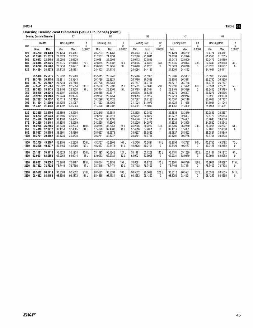
45
INCH Table
Housing Bearing-Seat Diameters (Values in Inches) (cont.)Bearing Outside Diameter F7 G7 H8 H7 H6
——————————————————————————————————————————————————————————————————————————————————————————————————————————————Inches Housing Bore Fit Housing Bore Fit Housing Bore Fit Housing Bore Fit Housing Bore Fit
mm ————————————————————————— in ————————————— in ——————————------------—— in ————————————— in ————————————— in Max. Min. Min. Max. 0.0000" Min. Max. 0.0000" Min. Max. 0.0000" Min. Max. 0.0000" Min. Max. 0.0000"
520 20.4724 20.4704 20.4754 20.4781 20.4733 20.4760 20.4724 20.4767 20.4724 20.4752 20.4724 20.4741 540 21.2598 21.2578 21.2628 21.2655 21.2607 21.2634 21.2598 21.2641 21.2598 21.2626 21.2598 21.2615 560 22.0472 22.0452 22.0502 22.0529 22.0481 22.0508 22.0472 22.0515 22.0472 22.0500 22.0472 22.0489 580 22.8346 22.8326 22.8376 22.8403 77 L 22.8355 22.8382 56 L 22.8346 22.8389 63 L 22.8346 22.8374 48 L 22.8346 22.8363 37 L600 23.6220 23.6200 23.6250 23.6277 30 L 23.6229 23.6256 9 L 23.6220 23.6263 0 23.6220 23.6248 0 23.6220 23.6237 0 620 24.4094 24.4074 24.4124 24.4151 24.4103 24.4130 24.4094 24.4137 24.4094 24.4122 24.4094 24.4111
——————————————————————————————————————————————————————————————————————————————————————————————————————————————25.5906 25.5876 25.5937 25.5969 25.5915 25.5947 25.5906 25.5955 25.5906 25.5937 25.5906 25.5926
670 26.3780 26.3750 26.3811 26.3843 26.3789 26.3821 26.3780 26.3829 26.3780 26.3811 26.3780 26.3800 680 26.7717 26.7687 26.7748 26.7780 26.7726 26.7758 26.7717 26.7766 26.7717 26.7748 26.7717 26.7737 700 27.5591 27.5561 27.5622 27.5654 93 L 27.5600 27.5632 71 L 27.5591 27.5640 79 L 27.5591 27.5622 61 L 27.5591 27.5611 50 L720 28.3465 28.3435 28.3496 28.3528 31 L 28.3474 28.3506 9 L 28.3465 28.3514 0 28.3465 28.3496 0 28.3465 28.3485 0 750 29.5276 29.5246 29.5307 29.5339 29.5285 29.5317 29.5276 29.5325 29.5276 29.5307 29.5276 29.5296 760 29.9213 29.9183 29.9244 29.9276 29.9222 29.9254 29.9213 29.9262 29.9213 29.9244 29.9213 29.9233 780 30.7087 30.7057 30.7118 30.7150 30.7096 30.7128 30.7087 30.7136 30.7087 30.7118 30.7087 30.7107 790 31.1024 31.0994 31.1055 31.1087 31.1033 31.1065 31.1024 31.1073 31.1024 31.1055 31.1024 31.1044 800 31.4961 31.4931 31.4992 31.5024 31.4970 31.5002 31.4961 31.5010 31.4961 31.4992 31.4961 31.4981
——————————————————————————————————————————————————————————————————————————————————————————————————————————————820 32.2835 32.2796 32.2869 32.2904 32.2845 32.2881 32.2835 32.3890 32.2835 32.2870 32.2835 32.2857 830 32.6772 32.6733 32.6806 32.6841 32.6782 32.6818 32.6772 32.6827 32.6772 32.6807 32.6772 32.6794 850 33.4646 33.4607 33.4680 33.4715 33.4656 33.4692 33.4646 33.4701 33.4646 33.4681 33.4646 33.4668 870 34.2520 34.2481 34.2554 34.2589 34.2530 34.2566 34.2520 34.2575 34.2520 34.2555 34.2520 34.2542 920 36.2205 36.2166 36.2239 36.2274 108 L 36.2215 36.2251 85 L 36.2205 36.2260 94 L 36.2205 36.2240 74 L 36.2205 36.2227 61 L950 37.4016 37.3977 37.4050 37.4085 34 L 37.4026 37.4062 10 L 37.4016 37.4071 0 37.4016 37.4051 0 37.4016 37.4038 0 980 38.5827 38.5788 38.5861 38.5896 38.5837 38.5873 38.5827 38.5882 38.5827 38.5862 38.5827 38.5849
1000 39.3701 39.3662 39.3735 39.3770 39.3711 39.3747 39.3701 39.3756 39.3701 39.3736 39.3701 39.3723 ——————————————————————————————————————————————————————————————————————————————————————————————————————————————1150 45.2756 45.2707 45.2795 45.2836 129 L 45.2767 45.2808 101 L 45.2756 45.2821 114 L 45.2756 45.2797 90 L 45.2756 45.2782 75 L1250 49.2126 49.2077 49.2165 49.2206 39 L 49.2137 49.2178 11 L 49.2126 49.2191 0 49.2126 49.2167 0 49.2126 49.2152 0
——————————————————————————————————————————————————————————————————————————————————————————————————————————————1400 55.1181 55.1118 55.1224 55.1274 156 L 55.1193 55.1242 124 L 55.1181 55.1258 140 L 55.1181 55.1230 112 L 55.1181 55.1212 94 L1600 62.9921 62.9858 62.9964 63.0014 43 L 62.9933 62.9982 12 L 62.9921 62.9998 0 62.9921 62.9970 0 62.9921 62.9952 0
——————————————————————————————————————————————————————————————————————————————————————————————————————————————1800 70.8661 70.8582 70.8708 70.8767 185 L 70.8674 70.8733 151 L 70.8661 70.8752 170 L 70.8661 70.8720 138 L 70.8661 70.8697 115 L2000 78.7402 78.7323 78.7449 78.7508 47 L 78.7415 78.7474 13 L 78.7402 78.7493 0 78.7402 78.7461 0 78.7402 78.7438 0
——————————————————————————————————————————————————————————————————————————————————————————————————————————————2300 90.5512 90.5414 90.5563 90.5632 218 L 90.5525 90.5594 180 L 90.5512 90.5622 208 L 90.5512 90.5581 167 L 90.5512 90.5555 141 L2500 98.4252 98.4154 98.4303 98.4372 51 L 98.4265 98.4334 13 L 98.4252 98.4362 0 98.4252 98.4321 0 98.4252 98.4295 0
——————————————————————————————————————————————————————————————————————————————————————————————————————————————
6a

46
INCH Table
Housing Bearing-Seat Diameters (Values in Inches) (cont.)Bearing Outside Diameter J6 J7 K6 K7 M6
——————————————————————————————————————————————————————————————————————————————————————————————————————————————Inches Housing Bore Fit Housing Bore Fit Housing Bore Fit Housing Bore Fit Housing Bore Fit
mm ————————————————————————— in ————————————— in ————————————— in ————————————— in ————————————— in Max. Min. Min. Max. 0.0000" Min. Max. 0.0000" Min. Max. 0.0000" Min. Max. 0.0000" Min. Max. 0.0000"
5 L 7 L 4 L 5 L 1 L16 0.6299 0.6296 0.6297 0.6301 0.6296 0.6303 0.6295 0.6300 0.6294 0.6301 0.6293 0.6297 2 T 3 T 4 T 5 T 6 T——————————————————————————————————————————————————————————————————————————————————————————————————————————————
19 0.7480 0.7476 0.7478 0.7483 0.7476 0.7485 0.7476 0.7481 0.7474 0.7482 0.7473 0.7478 22 0.8661 0.8657 0.8659 0.8664 0.8657 0.8666 0.8657 0.8662 0.8655 0.8663 0.8654 0.8659 24 0.9449 0.9445 0.9447 0.9452 7 L 0.9445 0.9454 9 L 0.9445 0.9450 5 L 0.9443 0.9451 6 L 0.9442 0.9447 2 L26 1.0236 1.0232 1.0234 1.0239 2 T 1.0232 1.0241 4 T 1.0232 1.0237 4 T 1.0230 1.0238 6 T 1.0229 1.0234 7 T28 1.1024 1.1020 1.1022 1.1027 1.1020 1.1029 1.1020 1.1025 1.1018 1.1026 1.1017 1.1022 30 1.1811 1.1807 1.1809 1.1814 1.1807 1.1816 1.1807 1.1812 1.1805 1.1813 1.1804 1.1809
——————————————————————————————————————————————————————————————————————————————————————————————————————————————32 1.2598 1.2594 1.2596 1.2602 1.2594 1.2604 1.2593 1.2599 1.2591 1.2601 1.2590 1.2596 35 1.3780 1.3776 1.3778 1.3784 1.3776 1.3786 1.3775 1.3781 1.3773 1.3783 1.3772 1.3778 37 1.4567 1.4563 1.4565 1.4571 8 L 1.4563 1.4573 10 L 1.4562 1.4568 5 L 1.4560 1.4570 7 L 1.4559 1.4565 2 L40 1.5748 1.5744 1.5746 1.5752 2 T 1.5744 1.5754 4 T 1.5743 1.5749 5 T 1.5741 1.5751 7 T 1.5740 1.5746 8 T42 1.6535 1.6531 1.6533 1.6539 1.6531 1.6541 1.6530 1.6536 1.6528 1.6538 1.6527 1.6533 47 1.8504 1.8500 1.8502 1.8508 1.8500 1.8510 1.8499 1.8505 1.8497 1.8507 1.8496 1.8502
——————————————————————————————————————————————————————————————————————————————————————————————————————————————52 2.0472 2.0467 2.0470 2.0477 2.0467 2.0479 2.0466 2.0474 2.0464 2.0476 2.0463 2.047 55 2.1654 2.1649 2.1652 2.1659 2.1649 2.1661 2.1648 2.1656 2.1646 2.1658 2.1645 2.1652 62 2.4409 2.4404 2.4407 2.4414 10 L 2.4404 2.4416 12 L 2.4403 2.4411 7 L 2.4401 2.4413 9 L 2.4400 2.4407 3 L68 2.6772 2.6767 2.6770 2.6777 2.6767 2.6779 2.6766 2.6774 2.6764 2.6776 2.6763 2.6770 72 2.8346 2.8341 2.8344 2.8351 2 T 2.8341 2.8353 5 T 2.8340 2.8348 6 T 2.8338 2.8350 8 T 2.8337 2.8344 9 T75 2.9527 2.9522 2.9525 2.9532 2.9522 2.9534 2.9521 2.9529 2.9519 2.9531 2.9518 2.9525 80 3.1496 3.1491 3.1494 3.1501 3.1491 3.1503 3.1490 3.1498 3.1488 3.1500 3.1487 3.1494
——————————————————————————————————————————————————————————————————————————————————————————————————————————————85 3.3465 3.3459 3.3463 3.3471 3.3460 3.3474 3.3458 3.3467 3.3455 3.3469 3.3454 3.3463 90 3.5433 3.5427 3.5431 3.5439 3.5428 3.5442 3.5426 3.5435 3.5423 3.5437 3.5422 3.5431 95 3.7402 3.7396 3.7400 3.7408 3.7397 3.7411 3.7395 3.7404 3.7392 3.7406 3.7391 3.7400
100 3.9370 3.9364 3.9368 3.9376 12 L 3.9365 3.9379 15 L 3.9363 3.9372 8 L 3.9360 3.9374 10 L 3.9359 3.9368 4 L110 4.3307 4.3301 4.3305 4.3313 2 T 4.3302 4.3316 5 T 4.3300 4.3309 7 T 4.3297 4.3311 10 T 4.3296 4.3305 11 T115 4.5276 4.5270 4.5274 4.5282 4.5271 4.5285 4.5269 4.5278 4.5266 4.5280 4.5265 4.5274 120 4.7244 4.7238 4.7242 4.7250 4.7239 4.7253 4.7237 4.7246 4.7234 4.7248 4.7233 4.7242
——————————————————————————————————————————————————————————————————————————————————————————————————————————————125 4.9213 4.9206 4.9210 4.9220 4.9207 4.9223 4.9205 4.9215 4.9202 4.9218 4.9200 4.9210 130 5.1181 5.1174 5.1178 5.1188 5.1175 5.1191 5.1173 5.1183 5.1170 5.1186 5.1168 5.1178 140 5.5118 5.5111 5.5115 5.5125 14 L 5.5112 5.5128 17 L 5.5110 5.5120 9 L 5.5107 5.5123 12 L 5.5105 5.5115 4 L145 5.7087 5.7080 5.7084 5.7094 3 T 5.7081 5.7097 6 T 5.7079 5.7089 8 T 5.7076 5.7092 11 T 5.7074 5.7084 13 T150 5.9055 5.9048 5.9052 5.9062 5.9049 5.9065 5.9047 5.9057 5.9044 5.9060 5.9042 5.9052
——————————————————————————————————————————————————————————————————————————————————————————————————————————————160 6.2992 6.2982 6.2989 6.2999 6.2986 6.3002 6.2984 6.2994 6.2981 6.2997 6.2979 6.2989 165 6.4961 6.4951 6.4958 6.4968 6.4955 6.4971 6.4953 6.4963 6.4950 6.4966 6.4948 6.4958 170 6.6929 6.6919 6.6926 6.6936 17 L 6.6923 6.6939 20 L 6.6921 6.6931 12 L 6.6918 6.6934 15 L 6.6916 6.6926 7 L180 7.0866 7.0856 7.0863 7.0873 3 T 7.0860 7.0876 6 T 7.0858 7.0868 8 T 7.0855 7.0871 11 T 7.0853 7.0863 13 T
——————————————————————————————————————————————————————————————————————————————————————————————————————————————190 7.4803 7.4791 7.4800 7.4812 7.4797 7.4815 7.4794 7.4805 7.4790 7.4808 7.4788 7.4800 200 7.8740 7.8728 7.8737 7.8749 7.8734 7.8752 7.8731 7.8742 7.8727 7.8745 7.8725 7.8737 210 8.2677 8.2665 8.2674 8.2686 8.2671 8.2689 8.2668 8.2679 8.2664 8.2682 8.2662 8.2674 215 8.4646 8.4634 8.4643 8.4655 21 L 8.4640 8.4658 24 L 8.4637 8.4648 14 L 8.4633 8.4651 17 L 8.4631 8.4643 9 L220 8.6614 8.6602 8.6611 8.6623 8.6608 8.6626 8.6605 8.6616 8.6601 8.6619 8.6599 8.6611 225 8.8583 8.8571 8.8580 8.8592 3 T 8.8577 8.8595 6 T 8.8574 8.8585 9 T 8.8570 8.8588 13 T 8.8568 8.8580 15 T230 9.0551 9.0539 9.0548 9.0560 9.0545 9.0563 9.0542 9.0553 9.0538 9.0556 9.0536 9.0548 240 9.4488 9.4476 9.4485 9.4497 9.4482 9.4500 9.4479 9.4490 9.4475 9.4493 9.4473 9.4485 250 9.8425 9.8413 9.8422 9.8434 9.8419 9.8437 9.8416 9.8427 9.8412 9.8430 9.8410 9.8422
——————————————————————————————————————————————————————————————————————————————————————————————————————————————260 10.2360 10.2350 10.2360 10.2370 10.2360 10.2380 10.2350 10.2360 10.2350 10.2370 10.2350 10.2360 270 10.6299 10.6285 10.6296 10.6309 10.6293 10.6313 10.6288 10.6301 10.6285 10.6305 10.6283 10.6295 280 11.0240 11.0220 11.0230 11.0250 24 L 11.0230 11.0250 28 L 11.0230 11.0240 16 L 11.0220 11.0240 20 L 11.0220 11.0230 10 L290 11.4173 11.4159 11.4170 11.4183 11.4167 11.4187 11.4162 11.4175 11.4159 11.4179 11.4157 11.4169 300 11.8110 11.8100 11.8110 11.8120 3 T 11.8100 11.8120 6 T 11.8100 11.8110 11 T 11.8100 11.8120 14 T 11.8090 11.8110 16 T310 12.2050 12.2030 12.2040 12.2060 12.2040 12.2060 12.2040 12.2050 12.2030 12.2050 12.2030 12.2040
——————————————————————————————————————————————————————————————————————————————————————————————————————————————320 12.5980 12.5970 12.5980 12.6000 12.5980 12.6000 12.5970 12.5990 12.5970 12.5990 12.5970 12.5980 340 13.3860 13.3840 13.3860 13.3870 13.3850 13.3870 13.3850 13.3860 13.3840 13.3870 13.3840 13.3850 360 14.1730 14.1720 14.1730 14.1740 27 L 14.1730 14.1750 31 L 14.1720 14.1740 19 L 14.1720 14.1740 23 L 14.1710 14.1730 12 L370 14.5670 14.5654 14.5667 14.5681 14.5663 14.5685 25.5659 14.5673 14.5654 14.5677 14.5652 14.5666 380 14.9610 14.9590 14.9600 14.9620 3 T 14.9600 14.9620 7 T 14.9600 14.9610 11 T 14.9590 14.9610 16 T 14.9590 14.9600 18 T400 15.7480 15.7460 15.7480 15.7490 15.7470 15.7500 15.7470 15.7480 15.7460 15.7490 15.7460 15.7480
——————————————————————————————————————————————————————————————————————————————————————————————————————————————420 16.5350 16.5340 16.5350 16.5370 16.5350 16.5370 16.5340 16.5360 16.5340 16.5360 16.5330 16.5350 440 17.3230 17.3210 17.3230 17.3240 31 L 17.3220 17.3250 35 L 17.3220 17.3230 21 L 17.3210 17.3240 25 L 17.3210 17.3220 14 L460 18.1100 18.1080 18.1100 18.1120 3 T 18.1090 18.1120 8 T 18.1090 18.1110 13 T 18.1080 18.1110 18 T 18.1080 18.1100 20 T480 18.8980 18.8960 18.8970 18.8990 18.8970 18.8990 18.8960 18.8980 18.8960 18.8980 18.8960 18.8970 500 19.6850 19.6830 19.6850 19.6860 19.6840 19.6870 19.6840 19.6850 19.6830 19.6860 19.6830 19.6850
——————————————————————————————————————————————————————————————————————————————————————————————————————————————
6a

47
INCH Table
Housing Bearing-Seat Diameters (Values in Inches) (cont.)Bearing Outside Diameter J6 J7 K6 K7 M6
——————————————————————————————————————————————————————————————————————————————————————————————————————————————Inches Housing Bore Fit Housing Bore Fit Housing Bore Fit Housing Bore Fit Housing Bore Fit
mm ————————————————————————— in ————————————— in ————————————— in ————————————— in ————————————— in Max. Min. Min. Max. 0.0000" Min. Max. 0.0000" Min. Max. 0.0000" Min. Max. 0.0000" Min. Max. 0.0000"
520 20.4720 20.4700 20.4720 20.4740 20.4720 20.4740 20.4710 20.4720 20.4700 20.4720 20.4700 20.4710 540 21.2600 21.2580 21.2600 21.2610 21.2590 21.2620 21.2580 21.2600 21.2570 21.2600 21.2570 21.2590 560 22.0472 22.0452 22.0442 22.0487 22.0463 22.0491 22.0455 22.0472 22.0444 22.0472 22.0444 22.0462 580 22.8350 22.8330 23.8340 22.8360 35 L 22.8340 22.8370 39 L 22.8330 22.8350 20 L 22.8320 22.8350 20 L 22.8320 22.8340 10 L600 23.6220 23.6200 23.6220 23.6240 3 T 23.6210 23.6240 9 T 23.6200 23.6220 17 T 23.6190 23.6220 28 T 23.6190 23.6210 28 T620 24.4090 24.4070 24.4090 24.4110 24.4090 24.4110 24.4080 24.4090 24.4070 24.4090 24.4070 24.4080
——————————————————————————————————————————————————————————————————————————————————————————————————————————————650 25.5910 25.5880 25.5900 25.5920 25.5900 25.5930 25.5890 25.5910 25.5880 25.5910 25.5880 25.5890 670 26.3780 26.3750 26.3780 26.3800 26.3770 26.3800 26.3760 26.3780 26.3750 26.3780 26.3750 26.3770680 26.7720 26.7690 26.7710 26.7730 26.7710 26.7740 26.7700 26.7720 26.7690 26.7720 26.7690 26.7710 700 27.5590 27.5560 27.5590 27.5610 46 L 27.5580 27.5610 52 L 27.5570 27.5590 30 L 27.5560 27.5590 30 L 27.5560 27.5580 18 L720 28.3470 28.3440 28.3460 28.3480 4 T 28.3460 28.3490 9 T 28.3450 28.3470 20 T 28.3430 28.3470 31 T 28.3430 28.3450 31 T750 29.5280 29.5250 29.5270 29.5290 29.5270 29.5300 29.5260 29.5280 29.5250 29.5280 29.5250 29.5260 760 29.9213 29.9183 29.9209 29.9229 29.9204 29.9235 29.9193 29.9213 29.9182 29.9213 29.9182 29.9201 780 30.7090 30.7060 30.7080 30.7100 30.7080 30.7110 30.7070 30.7090 30.7060 30.7090 30.7060 30.7080 790 31.1020 31.0990 31.1020 31.1040 31.1020 31.1050 31.1000 31.1020 31.0990 31.1020 31.0990 31.1010 800 31.4961 31.4931 31.4957 31.4977 31.4952 31.4962 31.4941 31.4961 31.4930 31.4961 31.4930 31.4949
——————————————————————————————————————————————————————————————————————————————————————————————————————————————820 32.2840 32.2800 32.2830 32.2850 32.2830 32.2860 32.2810 32.2840 32.2800 32.2840 32.2800 32.2820 830 32.6772 32.6733 32.6768 32.6790 32.6762 32.6797 32.6750 32.6772 32.6737 32.6772 32.6737 32.6759 850 33.4650 33.4610 33.4640 33.4660 33.4640 33.4670 33.4620 33.4650 33.4610 33.4650 33.4610 33.4630 870 34.2520 34.2480 34.2520 34.2540 34.2510 34.2550 34.2500 34.2520 34.2490 34.2520 34.2490 34.2510 920 36.2210 36.2170 36.2200 36.2220 57 L 36.2200 36.2230 64 L 36.2180 36.2210 39 L 36.2170 36.2210 39 L 36.2170 36.2190 26 L950 37.4020 37.3980 37.4010 37.4030 4 T 37.4010 37.4040 10 T 37.3990 37.4020 22 T 37.3980 37.4020 35 T 37.3980 37.4000 35 T980 38.5830 38.5790 38.5820 38.5850 38.5820 38.5850 38.5810 38.5830 38.5790 38.5830 38.5790 38.5810
1000*——————————————————————————————————————————————————————————————————————————————————————————————————————————————1150* 1250* ——————————————————————————————————————————————————————————————————————————————————————————————————————————————1400* 1600* ——————————————————————————————————————————————————————————————————————————————————————————————————————————————1800* 2000* ——————————————————————————————————————————————————————————————————————————————————————————————————————————————2300* 2500* ——————————————————————————————————————————————————————————————————————————————————————————————————————————————* Contact SKF Engineering for >1000 size range fit recommendations.
6a

48
INCH Table
Housing Bearing-Seat Diameters (Values in Inches) (cont.)Bearing Outside Diameter M7 N6 N7 P6 P7
——————————————————————————————————————————————————————————————————————————————————————————————————————————————Inches Housing Bore Fit Housing Bore Fit Housing Bore Fit Housing Bore Fit Housing Bore Fit
mm ————————————————————————— in ————————————— in ————————————— in ————————————— in ————————————— in Max. Min. Min. Max. 0.0000" Min. Max. 0.0000" Min. Max. 0.0000" Min. Max. 0.0000" Min. Max. 0.0000"
3 L 1 T 1 L 3 T 1 T16 0.6299 0.6296 0.6292 0.6299 0.6291 0.6295 0.6290 0.6297 0.6289 0.6293 0.6288 0.62957 T 8 T 9 T 10 T 11 T——————————————————————————————————————————————————————————————————————————————————————————————————————————————
19 0.7480 0.7476 0.7472 0.7480 0.7471 0.7476 0.7469 0.7477 0.7468 0.7473 0.7466 0.747422 0.8661 0.8657 0.8653 0.8661 0.8652 0.8657 0.8650 0.8658 0.8649 0.8654 0.8647 0.865524 0.9449 0.9445 0.9441 0.9449 4 L 0.9440 0.9445 0 0.9438 0.9446 1 L 0.9437 0.9442 3 T 0.9435 0.9443 2 T26 1.0236 1.0232 1.0228 1.0236 8 T 1.0227 1.0232 9 T 1.0225 1.0233 11 T 1.0224 1.0229 12 T 1.0222 1.0230 14 T28 1.1024 1.1020 1.1016 1.1024 1.1015 1.1020 1.1013 1.1021 1.1012 1.1017 1.1010 1.101830 1.1811 1.1807 1.1803 1.1811 1.1802 1.1807 1.1800 1.1808 1.1799 1.1804 1.1797 1.1805
——————————————————————————————————————————————————————————————————————————————————————————————————————————————32 1.2598 1.2594 1.2588 1.2598 1.2587 1.2593 1.2585 1.2595 1.2583 1.2590 1.2581 1.259135 1.3780 1.3776 1.3770 1.3780 4 L 1.3769 1.3775 1.3767 1.3777 1.3765 1.3772 1.3763 1.377337 1.4567 1.4563 1.4557 1.4567 10 T 1.4556 1.4562 1 T 1.4554 1.4564 1 L 1.4552 1.4559 4 T 1.4550 1.4560 3 T40 1.5748 1.5744 1.5738 1.5748 1.5737 1.5743 11 T 1.5735 1.5745 13 T 1.5733 1.5740 15 T 1.5731 1.5741 17 T42 1.6535 1.6531 1.6525 1.6535 1.6524 1.6530 1.6522 1.6532 1.6520 1.6527 1.6518 1.652847 1.8504 1.8500 1.8494 1.8504 1.8493 1.8499 1.8491 1.8501 1.8489 1.8496 1.8487 1.8497
——————————————————————————————————————————————————————————————————————————————————————————————————————————————52 2.0472 2.0467 2.0460 2.0472 2.0459 2.0466 2.0457 2.0468 2.0454 2.0462 2.0452 2.046455 2.1654 2.1649 2.1642 2.1654 5 L 2.1641 2.1648 2.1639 2.1650 2.1636 2.1644 2.1634 2.164662 2.4409 2.4404 2.4397 2.4409 12 T 2.4396 2.4403 1 T 2.4394 2.4405 1 L 2.4391 2.4399 5 T 2.4389 2.4401 3 T68 2.8346 2.8341 2.6760 2.6772 2.6759 2.6766 2.6760 2.6770 2.6750 2.6760 2.6752 2.676372 2.8346 2.8341 2.8334 2.8346 2.8333 2.8340 13 T 2.8331 2.8342 15 T 2.8328 2.8336 18 T 2.8326 2.8338 20 T75 3.1495 3.1491 2.9516 2.9528 2.9515 2.9522 2.9510 2.9520 2.9510 2.9520 2.9507 2.951980 3.1496 3.1491 3.1484 3.1496 3.1483 3.1490 3.1481 3.1492 3.1478 3.1486 3.1476 3.1488
——————————————————————————————————————————————————————————————————————————————————————————————————————————————85 3.3465 3.3459 3.3451 3.3465 3.3450 3.3459 3.3447 3.3461 3.3445 3.3453 3.3442 3.345690 3.5433 3.5427 3.5419 3.5433 3.5418 3.5427 3.5415 3.5429 3.5413 3.5421 3.5410 3.542495 3.9370 3.9364 3.7388 3.7402 3.7387 3.7395 3.7380 3.7400 3.7380 3.7390 3.7378 3.7392
100 3.9370 3.9364 3.9356 3.9370 6 L 3.9355 3.9364 0 3.9352 3.9366 2 L 3.9350 3.9358 6 T 3.9347 3.9361 3 T110 4.3307 4.3301 4.3293 4.3307 14 T 4.3292 4.3301 15 T 4.3289 4.3303 18 T 4.3287 4.3295 20 T 4.3284 4.3298 23 T115 4.5276 4.5270 4.5262 4.5276 4.5261 4.5270 4.5258 4.5272 4.5256 4.5264 4.5253 4.5267120 4.7244 4.7238 4.7230 4.7244 4.7229 4.7238 4.7226 4.7240 4.7224 4.7232 4.7221 4.7235
——————————————————————————————————————————————————————————————————————————————————————————————————————————————125 4.9213 4.9206 4.9197 4.9213 4.9195 4.9205 4.9193 4.9208 4.9189 4.9199 4.9186 4.9202130 5.1181 5.1174 5.1165 5.1181 7 L 5.1163 5.1173 5.1161 5.1176 5.1157 5.1167 5.1154 5.1170140 5.5118 5.5111 5.5102 5.5118 16 T 5.5100 5.5110 1 T 5.5098 5.5113 2 L 5.5094 5.5104 7 T 5.5091 5.5107 4 T145 5.7087 5.7080 5.7071 5.7087 5.7069 5.7079 18 T 5.7067 5.7082 20 T 5.7063 5.7073 24 T 5.7060 5.7076 27 T150 5.9055 5.9048 5.9039 5.9055 5.9037 5.9047 5.9035 5.9050 5.9031 5.9041 5.9028 5.9044
——————————————————————————————————————————————————————————————————————————————————————————————————————————————160 6.2992 6.2982 6.2976 6.2992 10 L 6.2974 6.2984 6.2972 6.2987 6.2968 6.2978 6.2965 6.2981165 6.6929 6.6919 6.4945 6.4961 6.4943 6.4953 6.4940 6.4960 6.4940 6.4950 6.4934 6.4950170 6.6929 6.6919 6.6913 6.6929 16 T 6.6911 6.6921 2 L 6.6909 6.6924 5 L 6.6905 6.6915 4 T 6.6902 6.6918 1 T180 7.0866 7.0856 7.0850 7.0866 7.0848 7.0858 18 T 7.0846 7.0861 20 T 7.0842 7.0852 24 T 7.0839 7.0855 27 T
——————————————————————————————————————————————————————————————————————————————————————————————————————————————190 7.4803 7.4791 7.4785 7.4803 7.4783 7.4794 7.4779 7.4797 7.4775 7.4787 7.4772 7.4790200 7.8740 7.8728 7.8722 7.8740 7.8720 7.8731 7.8716 7.8734 7.8712 7.8724 7.8709 7.8727210 8.2677 8.2665 8.2659 8.2677 8.2657 8.2668 8.2653 8.2671 8.2649 8.2661 8.2646 8.2664215 8.4646 8.4634 8.4628 8.4646 12 L 8.4626 8.4637 3 L 8.4622 8.4640 6 L 8.4618 8.4630 4 T 8.4615 8.4633 1 T220 8.8583 8.8571 8.6596 8.6614 8.6594 8.6606 8.6590 8.6610 8.6590 8.6600 8.6583 8.6601225 8.8583 9.0539 9.0571 8.8583 18 T 8.8563 8.8574 20 T 8.8559 8.8577 24 T 8.8555 8.8567 28 T 8.8552 8.8570 31 T230 9.4488 9.4476 9.0533 9.0551 9.0531 9.0543 9.0530 9.0550 9.0520 9.0540 9.0520 9.0538240 9.4488 9.4476 9.4470 9.4488 9.4468 9.4479 9.4464 9.4482 9.4460 9.4472 9.4457 9.4475250 9.8425 9.8413 9.8407 9.8425 9.8405 9.8416 9.8401 9.8419 9.8397 9.8409 9.8394 9.8412
——————————————————————————————————————————————————————————————————————————————————————————————————————————————260 10.2362 10.2348 10.2342 10.2362 10.2340 10.2352 10.2336 10.2356 10.2331 10.2343 10.2327 10.2348270 11.0236 11.0222 10.6279 10.6299 10.6277 10.6289 10.6270 10.6290 10.6270 10.6280 10.6265 10.6285280 11.0236 11.0222 11.0216 11.0236 14 L 11.0214 11.0226 4 L 11.0210 11.0230 8 L 11.0205 11.0217 5 T 11.0201 11.0222 0290 11.8110 11.8096 11.4153 11.4173 11.4151 11.4163 11.4150 11.4170 11.4140 11.4150 11.4139 11.4159300 11.8110 11.8096 11.8090 11.8110 20 T 11.8088 11.8100 22 T 11.8084 11.8104 26 T 11.8079 11.8091 31 T 11.8075 11.8096 35 T310 12.2047 12.2033 12.2027 12.2047 12.2025 12.2037 12.2021 12.2041 12.2016 12.2028 12.2012 12.2033
——————————————————————————————————————————————————————————————————————————————————————————————————————————————320 12.5984 12.5968 12.5962 12.5984 12.5960 12.5974 12.5955 12.5978 12.5950 12.5964 12.5945 12.5968340 13.3858 13.3842 12.3836 12.3858 16 L 13.3834 13.3848 13.3829 13.3852 13.3824 13.3838 13.3819 13.3842360 14.1732 14.1716 14.1710 14.1732 22 T 14.1708 14.1722 6 L 14.1703 14.1726 10 L 14.1698 14.1712 4 T 14.1693 14.1716 0370 14.9607 14.9591 14.5647 14.5669 14.5645 14.5659 14.5640 14.5660 14.5640 14.5650 14.5631 14.5653380 14.9606 14.9590 14.9584 14.9606 14.9582 14.9596 24 T 14.9577 14.9600 29 T 14.9572 14.9586 34 T 14.9567 14.9590 39 T400 15.7480 15.7464 15.7458 15.7480 15.7456 15.7470 15.7451 15.7474 15.7446 15.7460 15.7441 15.7464
——————————————————————————————————————————————————————————————————————————————————————————————————————————————420 16.5354 16.5336 16.5329 16.5354 16.5328 16.5343 16.5323 16.5347 16.5317 16.5332 16.5311 16.5336440 17.3228 17.3210 17.3203 17.3228 18 L 17.3202 17.3217 7 L 17.3197 17.3221 11 L 17.3191 17.3206 4 T 17.3185 17.3210 0460 18.1102 18.1084 18.1077 18.1102 25 T 18.1076 18.1091 26 T 18.1071 18.1095 31 T 18.1065 18.1080 37 T 18.1059 18.1084 43 T480 18.8976 18.8958 18.8951 18.8976 18.8950 18.8965 18.8945 18.8969 18.8939 18.8954 18.8933 18.8958500 19.6850 19.6832 19.6825 19.6850 19.6824 19.6839 19.6819 19.6843 19.6813 19.6828 19.6807 19.6832
——————————————————————————————————————————————————————————————————————————————————————————————————————————————
6a

49
INCH Table
Housing Bearing-Seat Diameters (Values in Inches) (cont.)Bearing Outside Diameter M7 N6 N7 P6 P7
——————————————————————————————————————————————————————————————————————————————————————————————————————————————Inches Housing Bore Fit Housing Bore Fit Housing Bore Fit Housing Bore Fit Housing Bore Fit
mm ————————————————————————— in ————————————— in ————————————— in ————————————— in ————————————— in Max. Min. Min. Max. 0.0000" Min. Max. 0.0000" Min. Max. 0.0000" Min. Max. 0.0000" Min. Max. 0.0000"
520 20.4724 20.4704 20.4686 20.4714 20.4689 20.4707 20.4679 20.4707 20.4676 20.4693 20.4666 20.4693 540 21.2598 21.2578 21.2560 21.2588 21.2563 21.2581 21.2553 21.2581 21.2550 21.2567 21.2540 21.2567 560 22.0472 22.0452 22.0435 22.0462 22.0438 22.0455 22.0430 22.0460 22.0420 22.0440 22.0414 22.0442 580 22.8346 22.8326 22.8308 22.8336 10 L 22.8311 22.8329 3 L 22.8301 22.8329 3 L 22.8298 22.8315 11 T 22.8288 22.8315 11 T600 23.6220 23.6200 23.6182 23.6210 38 T 23.6185 23.6203 35 T 23.6175 23.6203 45 T 23.6172 23.6189 48 T 23.6162 23.6189 58 T620 24.4094 24.4074 24.4056 24.4084 24.4059 24.4077 24.4049 24.4077 24.4046 24.4063 24.4036 24.4063
——————————————————————————————————————————————————————————————————————————————————————————————————————————————650 25.5906 25.5876 25.5863 25.5894 25.5867 25.5886 25.5855 25.5886 25.5852 25.5871 25.5840 25.5871 670 26.3780 26.3750 26.3737 26.3768 26.3741 26.3760 26.3729 26.3760 26.3726 26.3745 26.3714 26.3745 680 26.7717 26.7687 26.7674 26.7705 26.7678 26.7697 26.7666 26.7697 26.7663 26.7682 26.7651 26.7682 700 27.5591 27.5561 27.5548 27.5579 18 L 27.5552 27.5571 10 L 27.5540 27.5571 10 L 27.5537 27.5556 5 T 27.5525 27.5556 5 T720 28.3465 28.3435 28.3422 28.3453 43 T 28.3426 28.3445 39 T 28.3414 28.3445 51 T 28.3411 28.3430 54 T 28.3399 28.3430 66 T750 29.5276 29.5246 29.5233 29.5264 29.5237 29.5256 29.5225 29.5256 29.5222 29.5241 29.5210 29.5241 760 29.9213 29.9183 29.9169 29.9201 29.9173 29.9193 29.9160 29.9190 29.9160 29.9180 29.9146 29.9178 780 30.7087 30.7057 30.7044 30.7075 30.7048 30.7067 30.7036 30.7077 30.7033 30.7052 30.7021 30.7052 790 31.1024 31.0994 31.0981 31.1012 31.0985 31.1004 31.0973 31.1004 31.0970 31.0989 31.0958 31.0989 800 31.4961 31.4931 31.4917 31.4949 31.4921 31.4941 31.4910 31.4940 31.4910 31.4930 31.4894 31.4926
——————————————————————————————————————————————————————————————————————————————————————————————————————————————820 32.2835 32.2796 32.2786 32.2822 32.2791 32.2813 31.2778 32.2813 32.2774 32.2796 32.2760 32.2796 830 32.6772 32.6733 32.6723 32.6758 32.6728 32.6750 32.6710 32.6750 32.6710 32.6730 32.6697 32.6732 850 33.4646 33.4607 33.4597 33.4633 26 L 33.4602 33.4624 33.4589 33.4624 33.4585 33.4607 33.4571 33.4607 870 34.2520 34.2481 34.2471 34.2507 49 T 34.2476 34.2498 17 L 34.2463 34.2498 17 L 34.2459 34.2481 0 34.2445 34.2481 0 920 36.2205 36.2166 36.2156 36.2192 36.2161 36.2183 44 T 36.2148 36.2183 57 T 36.2144 36.2166 61 T 36.2130 36.2166 75 T950 37.4016 37.3977 37.3967 37.4003 37.3972 37.3994 37.3959 37.3994 37.3955 37.3977 37.3941 37.3977 980 38.5827 38.5788 38.5778 38.5814 38.5783 38.5805 38.5770 38.5805 38.5766 38.5788 38.5752 38.5788 1000 39.3701 39.3662 39.3652 39.3688 39.3657 39.3679 39.3644 39.3679 39.3640 39.3662 39.3626 39.3662
——————————————————————————————————————————————————————————————————————————————————————————————————————————————1150 45.2756 45.2707 45.2699 45.2740 33 L 45.2704 45.2730 23 L 45.2689 45.2730 23 L 45.2683 45.2709 2 L 45.2667 45.2709 2 L1250 49.2126 49.2077 49.2069 49.2110 57 T 49.2074 49.2100 52 T 49.2059 49.2100 67 T 49.2053 49.2079 73 T 40.2037 49.2079 89 T
——————————————————————————————————————————————————————————————————————————————————————————————————————————————1400 55.1181 55.1118 55.1113 55.1162 44 L 55.1120 55.1150 32 L 55.1101 55.1150 32 L 55.1095 55.1126 8 L 55.1077 55.1126 8 L1600 62.9921 62.9858 62.9853 62.9902 68 T 62.9860 62.9890 61 T 62.9841 62.9890 80 T 62.9835 62.9866 86 T 62.9817 62.9866 104 T
——————————————————————————————————————————————————————————————————————————————————————————————————————————————1800 70.8661 70.8582 70.8579 70.8638 56 L 70.8589 70.8625 43 L 70.8566 70.8625 43 L 70.8558 70.8594 12 L 70.8535 70.8594 12 L2000 78.7402 78.7323 78.7320 78.7379 82 T 78.7330 78.7366 72 T 78.7307 78.7366 95 T 78.7299 78.7335 103 T 78.7276 78.7335 126 T
——————————————————————————————————————————————————————————————————————————————————————————————————————————————2300 90.5512 90.5414 90.5416 90.5485 71 L 90.5425 90.5469 55 L 90.5400 90.5469 55 L 90.5392 90.5435 21 L 90.5366 90.5435 21 L2500 98.4252 98.4154 98.4156 98.4225 96 T 98.4165 98.4209 87 T 98.4140 98.4209 112 T 98.4132 98.4175 120 T 98.4106 98.4175 146 T
——————————————————————————————————————————————————————————————————————————————————————————————————————————————
6a

50
MM Table
Housing Bearing-Seat Diameters (Values in mm) Bearing Outside Diameter F7 G7 H8 H7 H6
——————————————————————————————————————————————————————————————————————————————————————————————————————————————mm Housing Bore Fit in Housing Bore Fit in Housing Bore Fit in Housing Bore Fit in Housing Bore Fit in
mm ———————————————————————— µm ———————----------------—-—----—–-— µm ————————————— µm ————————————— µm ————————————— µmMax. Min. Min. Max. (0.001 mm) Min. Max. (0.001 mm) Min. Max. (0.001 mm) Min. Max. (0.001 mm) Min. Max. (0.001 mm)
42 L 28 L 35 L 26 L 19 L16 16.000 15.992 16.016 16.034 16.006 16.020 16.000 16.027 16.000 16.018 16.000 16.01116 L 6 L 0 0 0——————————————————————————————————————————————————————————————————————————————————————————————————————————————
19 19.000 18.991 19.020 19.041 19.007 19.028 19.000 19.033 19.000 19.021 19.000 19.01322 22.000 21.991 22.020 22.041 22.007 22.028 22.000 22.033 22.000 22.021 22.000 22.01324 24.000 23.991 24.020 24.041 50 L 24.007 24.028 37 L 24.000 24.033 42 L 24.000 24.021 30 L 24.000 24.013 22 L26 26.000 25.991 26.020 26.041 20 L 26.007 26.028 7 L 26.000 26.033 0 26.000 26.021 0 26.000 26.013 028 28.000 27.991 28.020 28.041 28.007 28.028 28.000 28.033 28.000 28.021 28.000 28.01330 30.000 29.991 30.020 30.041 30.007 30.028 30.000 30.033 30.000 30.021 30.000 30.013
——————————————————————————————————————————————————————————————————————————————————————————————————————————————32 32.000 31.989 32.025 32.050 32.009 32.034 32.000 32.039 32.000 32.025 32.000 32.01635 35.000 34.989 35.025 35.050 35.009 35.034 35.000 35.039 35.000 35.025 35.000 35.01637 37.000 36.989 37.025 37.050 61 L 37.009 37.034 45 L 37.000 37.039 50 L 37.000 37.025 36 L 37.000 37.016 27 L40 40.000 39.989 40.025 40.050 25 L 40.009 40.034 9 L 40.000 40.039 0 40.000 40.025 0 40.000 40.016 042 42.000 41.989 42.025 42.050 42.009 42.034 42.000 42.039 42.000 42.025 42.000 42.01647 47.000 46.989 47.025 47.050 47.009 47.034 47.000 47.039 47.000 47.025 47.000 47.016
——————————————————————————————————————————————————————————————————————————————————————————————————————————————52 52.000 51.987 52.030 52.060 52.010 52.040 52.000 52.046 52.000 52.030 52.000 52.01955 55.000 54.987 55.030 55.060 55.010 55.040 55.000 55.046 55.000 55.030 55.000 55.01962 62.000 61.987 62.030 62.060 73 L 62.010 62.040 53 L 62.000 62.046 59 L 62.000 62.030 43 L 62.000 62.019 32 L68 68.000 67.987 68.030 68.060 68.010 68.040 68.000 68.046 68.000 68.030 68.000 68.01972 72.000 71.987 72.030 72.060 30 L 72.010 72.040 10 L 72.000 72.046 0 72.000 72.030 0 72.000 72.019 075 75.000 74.987 75.030 75.060 75.010 75.040 75.000 75.046 75.000 75.030 75.000 75.01980 80.000 79.987 80.030 80.060 80.010 80.040 80.000 80.046 80.000 80.030 80.000 80.019
——————————————————————————————————————————————————————————————————————————————————————————————————————————————85 85.000 84.985 85.036 85.071 85.012 85.047 85.000 85.054 85.000 85.035 85.000 85.02290 90.000 89.985 90.036 90.071 90.012 90.047 90.000 90.054 90.000 90.035 90.000 90.02295 95.000 94.985 95.036 95.071 95.012 95.047 95.000 95.054 95.000 95.035 95.000 95.022
100 100.000 99.985 100.036 100.071 86 L 100.012 100.047 62 L 100.000 100.054 69 L 100.000 100.035 50 L 100.000 100.022 37 L110 110.000 109.985 110.036 110.071 36 L 110.012 110.047 12 L 110.000 110.054 0 110.000 110.035 0 110.000 110.022 0115 115.000 114.985 115.036 115.071 115.012 115.047 115.000 115.054 115.000 115.035 115.000 115.022120 120.000 119.985 120.036 120.071 120.012 120.047 120.000 120.054 120.000 120.035 120.000 120.022
——————————————————————————————————————————————————————————————————————————————————————————————————————————————125 125.000 124.982 125.043 125.083 125.014 125.054 125.000 125.063 125.000 125.040 125.000 125.025130 130.000 129.982 130.043 130.083 130.014 130.054 130.000 130.063 130.000 130.040 130.000 130.025140 140.000 139.982 140.043 140.083 101 L 140.014 140.054 72 L 140.000 140.063 81 L 140.000 140.040 58 L 140.000 140.025 43 L145 145.000 144.982 145.043 145.083 43 L 145.014 145.054 14 L 145.000 145.063 0 145.000 145.040 0 145.000 145.025 0150 150.000 149.982 150.043 150.083 150.014 150.054 150.000 150.063 150.000 150.040 150.000 150.025
——————————————————————————————————————————————————————————————————————————————————————————————————————————————160 160.000 159.975 160.043 160.083 160.014 160.054 160.000 160.063 160.000 160.040 160.000 160.025165 165.000 164.975 165.043 165.083 165.014 165.054 165.000 165.063 165.000 165.040 165.000 165.025170 170.000 169.975 170.043 170.083 108 L 170.014 170.054 79 L 170.000 170.063 88 L 170.000 170.040 65 L 170.000 170.025 50 L180 180.000 179.975 180.043 180.083 43 L 180.014 180.054 14 L 180.000 180.063 0 180.000 180.040 0 180.000 180.025 0
——————————————————————————————————————————————————————————————————————————————————————————————————————————————190 190.000 189.970 190.050 190.096 190.015 190.061 190.000 190.072 190.000 190.046 190.000 190.029200 200.000 199.970 200.050 200.096 200.015 200.061 200.000 200.072 200.000 200.046 200.000 200.029210 210.000 209.970 210.050 210.096 210.015 210.061 210.000 210.072 210.000 210.046 210.000 210.029215 215.000 214.970 215.050 215.096 126 L 215.015 215.061 91 L 215.000 215.072 102 L 215.000 215.046 76 L 215.000 215.029 59 L220 220.000 219.970 220.050 220.096 220.015 220.061 220.000 220.072 220.000 220.046 220.000 220.029225 225.000 224.970 225.050 225.096 50 L 225.015 225.061 15 L 225.000 225.072 0 225.000 225.046 0 225.000 225.029 0230 230.000 229.970 230.050 230.096 230.015 230.061 230.000 230.072 230.000 230.046 230.000 230.029240 240.000 239.970 240.050 240.096 240.015 240.061 240.000 240.072 240.000 240.046 240.000 240.029250 250.000 249.970 250.050 250.096 250.015 250.061 250.000 250.072 250.000 250.046 250.000 250.029
——————————————————————————————————————————————————————————————————————————————————————————————————————————————260 260.000 259.965 260.056 260.108 260.017 260.069 260.000 260.081 260.000 260.052 260.000 260.032270 270.000 269.965 270.056 270.108 270.017 270.069 270.000 270.081 270.000 270.052 270.000 270.032280 280.000 279.965 280.056 280.108 143 L 280.017 280.069 104 L 280.000 280.081 116 L 280.000 280.052 87 L 280.000 280.032 67 L290 290.000 289.965 290.056 290.108 290.017 290.069 290.000 290.081 290.000 290.052 290.000 290.032300 300.000 299.965 300.056 300.108 56 L 300.017 300.069 17 L 300.000 300.081 0 300.000 300.052 0 300.000 300.032 0310 310.000 309.965 310.056 310.108 310.017 310.069 310.000 310.081 310.000 310.052 310.000 310.032
——————————————————————————————————————————————————————————————————————————————————————————————————————————————320 320.000 319.960 320.062 320.119 320.018 320.075 320.000 320.089 320.000 320.057 320.000 320.036340 340.000 339.960 340.062 340.119 340.018 340.075 340.000 340.089 340.000 340.057 340.000 340.036360 360.000 359.960 360.062 360.119 159 L 360.018 360.075 115 L 360.000 360.089 129 L 360.000 360.057 97 L 360.000 360.036 76 L370 370.000 369.960 370.062 370.119 370.018 370.075 370.000 370.089 370.000 370.057 370.000 370.036380 380.000 379.960 380.062 380.119 62 L 380.018 380.075 18 L 380.000 380.089 0 380.000 380.057 0 380.000 380.036 0400 400.000 399.960 400.062 400.119 400.018 400.075 400.000 400.089 400.000 400.057 400.000 400.036
——————————————————————————————————————————————————————————————————————————————————————————————————————————————420 420.000 419.955 420.068 420.131 420.020 420.083 420.000 420.097 420.000 420.063 420.000 420.040440 440.000 439.955 440.068 440.131 176 L 440.020 440.083 128 L 440.000 440.097 142 L 440.000 440.063 108 L 440.000 440.040 85 L460 460.000 459.955 460.068 460.131 68 L 460.020 460.083 20 L 460.000 460.097 0 460.000 460.063 0 460.000 460.040 0480 480.000 479.955 480.068 480.131 480.020 480.083 480.000 480.097 480.000 480.063 480.000 480.040500 500.000 499.955 500.068 500.131 500.020 500.083 500.000 500.097 500.000 500.063 500.000 500.040
——————————————————————————————————————————————————————————————————————————————————————————————————————————————
6b

51
MM Table
Housing Bearing-Seat Diameters (Values in mm) (cont.)Bearing Outside Diameter F7 G7 H8 H7 H6
——————————————————————————————————————————————————————————————————————————————————————————————————————————————mm Housing Bore Fit in Housing Bore Fit in Housing Bore Fit in Housing Bore Fit in Housing Bore Fit in
mm ————————————————————————— µm ———————————-----— µm ----—----——---————————— µm ———————————---------— µm —--------——————————-------------- µmMax. Min. Min. Max. (0.001 mm) Min. Max. (0.001 mm) Min. Max. (0.001 mm) Min. Max. (0.001 mm) Min. Max. (0.001 mm)
520 520.000 519.950 520.076 520.146 520.022 520.092 520.000 520.110 520.000 520.070 520.000 520.044540 540.000 539.950 540.076 540.146 540.022 540.092 540.000 540.110 540.000 540.070 540.000 540.044560 560.000 559.950 560.076 560.146 560.022 560.092 560.000 560.110 560.000 560.070 560.000 560.044580 580.000 579.950 580.076 580.146 196 L 580.022 580.092 142 L 580.000 580.110 160 L 580.000 580.070 120 L 580.000 580.044 94 L600 600.000 599.950 600.076 600.146 76 L 600.022 600.092 22 L 600.000 600.110 0 600.000 600.070 0 600.000 600.044 0620 620.000 619.950 620.076 620.146 620.022 620.092 620.000 620.110 620.000 620.070 620.000 620.044
——————————————————————————————————————————————————————————————————————————————————————————————————————————————650 650.000 649.925 650.080 650.160 650.024 650.104 650.000 650.125 650.000 650.080 650.000 650.050670 670.000 669.925 670.080 670.160 670.024 670.104 670.000 670.125 670.000 670.080 670.000 670.050680 680.000 679.925 680.080 680.160 680.024 680.104 680.000 680.125 680.000 680.080 680.000 680.050700 700.000 699.925 700.080 700.160 235 L 700.024 700.104 179 L 700.000 700.125 200 L 700.000 700.080 155 L 700.000 700.050 125 L720 720.000 719.925 720.080 720.160 80 L 720.024 720.104 24 L 720.000 720.125 0 720.000 720.080 0 720.000 720.050 0750 750.000 749.925 750.080 750.160 750.024 750.104 750.000 750.125 750.000 750.080 750.000 750.050760 760.000 759.925 760.080 760.160 760.024 760.104 760.000 760.125 760.000 760.080 760.000 760.050780 780.000 779.925 780.080 780.160 780.024 780.104 780.000 780.125 780.000 780.080 780.000 780.050790 790.000 789.925 790.080 790.160 790.024 790.104 790.000 790.125 790.000 790.080 790.000 790.050800 800.000 799.925 800.080 800.160 800.024 800.104 800.000 800.125 800.000 800.080 800.000 800.050
——————————————————————————————————————————————————————————————————————————————————————————————————————————————820 820.000 819.900 820.086 820.176 820.026 820.116 820.000 820.140 820.000 820.090 820.000 820.056830 830.000 829.900 830.086 830.176 830.026 830.116 830.000 830.140 830.000 830.090 830.000 830.056850 850.000 849.900 850.086 850.176 850.026 850.116 850.000 850.140 850.000 850.090 850.000 850.056870 870.000 869.900 870.086 870.176 870.026 870.116 870.000 870.140 870.000 870.090 870.000 870.056920 920.000 919.900 920.086 920.176 276 L 920.026 920.116 216 L 920.000 920.140 240 L 920.000 920.090 190 L 920.000 920.056 156 L950 950.000 949.900 950.086 950.176 86 L 950.026 950.116 26 L 950.000 950.140 0 950.000 950.090 0 950.000 950.056 0980 980.000 979.900 980.086 980.176 980.026 980.116 980.000 980.140 980.000 980.090 980.000 980.0561000 1000.000 999.900 1000.086 1000.176 1000.026 1000.116 1000.000 1000.140 1000.000 1000.090 1000.000 1000.056
——————————————————————————————————————————————————————————————————————————————————————————————————————————————1150 1150.000 1149.875 1150.098 1150.203 328 L 1150.028 1150.133 258 L 1150.000 1150.165 290 L 1150.000 1150.105 230 L 1150.000 1150.066 191 L1250 1250.000 1249.875 1250.098 1250.203 98 L 1250.028 1250.133 28 L 1250.000 1250.165 0 1250.000 1250.105 0 1250.000 1250.066 0
——————————————————————————————————————————————————————————————————————————————————————————————————————————————1400 1400.000 1399.840 1400.110 1400.235 395 L 1400.030 1400.155 315 L 1400.000 1400.195 355 L 1400.000 1400.125 285 L 1400.000 1400.078 238 L1600 1600.000 1599.840 1600.110 1600.235 110 L 1600.030 1600.155 30 L 1600.000 1600.195 0 1600.000 1600.125 0 1600.000 1600.078 0
——————————————————————————————————————————————————————————————————————————————————————————————————————————————1800 1800.000 1799.800 1800.120 1800.270 470 L 1800.032 1800.182 382 L 1800.000 1800.230 430 L 1800.000 1800.150 350 L 1800.000 1800.092 292 L2000 2000.000 1999.800 2000.120 2000.270 120 L 2000.032 2000.182 32 L 2000.000 2000.230 0 2000.000 2000.150 0 2000.000 2000.092 0
——————————————————————————————————————————————————————————————————————————————————————————————————————————————2300 2300.000 2299.750 2300.130 2300.305 555 L 2300.034 2300.209 459 L 2300.000 2300.280 530 L 2300.000 2300.175 425 L 2300.000 2300.110 360 L2500 2500.000 2499.750 2500.130 2500.305 130 L 2500.034 2500.209 34 L 2500.000 2500.280 0 2500.000 2500.175 0 2500.000 2500.110 0
——————————————————————————————————————————————————————————————————————————————————————————————————————————————
6b

52
MM Table
Housing Bearing-Seat Diameters (Values in mm) (cont.)Bearing Outside Diameter J6 J7 K6 K7 M6
——————————————————————————————————————————————————————————————————————————————————————————————————————————————mm Housing Bore Fit in Housing Bore Fit in Housing Bore Fit in Housing Bore Fit in Housing Bore Fit in
mm ————————————————————————— µm ————————————— µm ————————————— µm ————————-----------———— µm ————————————— µmMax. Min. Min. Max. (0.001 mm) Min. Max. (0.001 mm) Min. Max. (0.001 mm) Min. Max. (0.001 mm) Min. Max. (0.001 mm)
14 L 18 L 10 L 14 L 4 L16 16.000 15.992 15.995 16.006 15.992 16.010 15.991 16.002 15.988 16.006 15.985 15.9965 T 8 T 9 T 12 T 15 T——————————————————————————————————————————————————————————————————————————————————————————————————————————————
19 19.000 18.991 18.995 19.008 18.991 19.012 18.989 19.002 18.985 19.006 18.983 18.99622 22.000 21.991 21.995 22.008 21.991 22.012 21.989 22.002 21.985 22.006 21.983 21.99624 24.000 23.991 23.995 24.008 17 L 23.991 24.012 21 L 23.989 24.002 11 L 23.985 24.006 15 L 23.983 23.996 5 L26 26.000 25.991 25.995 26.008 5 T 25.991 26.012 9 T 25.989 26.002 11 T 25.985 26.006 15 T 25.983 25.996 17 T28 28.000 27.991 27.995 28.008 27.991 28.012 27.989 28.002 27.985 28.006 27.983 27.99630 30.000 29.991 29.995 30.008 29.991 30.012 29.989 30.002 29.985 30.006 29.983 29.996
——————————————————————————————————————————————————————————————————————————————————————————————————————————————32 32.000 31.989 31.994 32.010 31.989 32.014 31.987 32.003 31.982 32.007 31.980 31.99635 35.000 34.989 34.994 35.010 34.989 35.014 34.987 35.003 34.982 35.007 34.980 34.99637 37.000 36.989 36.994 37.010 21 L 36.989 37.014 25 L 36.987 37.003 14 L 36.982 37.007 18 L 36.980 36.996 7 L40 40.000 39.989 39.994 40.010 6 T 39.989 40.014 11 T 39.987 40.003 13 T 39.982 40.007 18 T 39.980 39.996 20 T42 42.000 41.989 41.994 42.010 41.989 42.014 41.987 42.003 41.982 42.007 41.980 41.99647 47.000 46.989 46.994 47.010 46.989 47.014 46.987 47.003 46.982 47.007 46.980 46.996
——————————————————————————————————————————————————————————————————————————————————————————————————————————————52 52.000 51.987 51.994 52.013 51.988 52.018 51.985 52.004 51.979 52.009 51.976 51.99555 55.000 54.987 54.994 55.013 54.988 55.018 54.985 55.004 54.979 55.009 54.976 54.99562 62.000 61.987 61.994 62.013 26 L 61.988 62.018 31 L 61.985 62.004 17 L 61.979 62.009 22 L 61.976 61.995 8 L68 68.000 67.987 67.994 68.013 67.988 68.018 67.985 68.004 67.979 68.009 67.976 67.99572 72.000 71.987 71.994 72.013 6 T 71.988 72.018 12 T 71.985 72.004 15 T 71.979 72.009 21 T 71.976 71.995 24 T75 75.000 74.987 74.994 75.013 74.988 75.018 74.985 75.004 74.979 75.009 74.976 74.99580 80.000 79.987 79.994 80.013 79.988 80.018 79.985 80.004 79.979 80.009 79.976 79.995
——————————————————————————————————————————————————————————————————————————————————————————————————————————————85 85.000 84.985 84.994 85.016 84.987 85.022 84.982 85.004 84.975 85.010 84.972 84.99490 90.000 89.985 89.994 90.016 89.987 90.022 89.982 90.004 89.975 90.010 89.972 89.99495 95.000 94.985 94.994 95.016 94.987 95.022 94.982 95.004 94.975 95.010 94.972 94.994
100 100.000 99.985 99.994 100.016 31 L 99.987 100.022 37 L 99.982 100.004 19 L 99.975 100.010 25 L 99.972 99.994 9 L110 110.000 109.985 109.994 110.016 6 T 109.987 110.022 13 T 109.982 110.004 18 T 109.975 110.010 25 T 109.972 109.994 28 T115 115.000 114.985 114.994 115.016 114.987 115.022 114.982 115.004 114.975 115.010 114.972 114.994120 120.000 119.985 119.994 120.016 119.987 120.022 119.982 120.004 119.975 120.010 119.972 119.994
——————————————————————————————————————————————————————————————————————————————————————————————————————————————125 125.000 124.982 124.993 125.018 124.986 125.026 124.979 125.004 124.972 125.012 124.967 124.992130 130.000 129.982 129.993 130.018 129.986 130.026 129.979 130.004 129.972 130.012 129.967 129.992140 140.000 139.982 139.993 140.018 36 L 139.986 140.026 44 L 139.979 140.004 22 L 139.972 140.012 30 L 139.967 139.992 10 L145 145.000 144.982 144.993 145.018 7 T 144.986 145.026 14 T 144.979 145.004 21 T 144.972 145.012 28 T 144.967 144.992 33 T150 150.000 149.982 149.993 150.018 149.986 150.026 149.979 150.004 149.972 150.012 149.967 149.992
——————————————————————————————————————————————————————————————————————————————————————————————————————————————160 160.000 159.975 159.993 160.018 159.986 160.026 159.979 160.004 159.972 160.012 159.967 159.992165 165.000 164.975 164.993 165.018 164.986 165.026 164.979 165.004 164.972 165.012 164.967 164.992170 170.000 169.975 169.993 170.018 43 L 169.986 170.026 51 L 169.979 170.004 29 L 169.972 170.012 37 L 169.967 169.992 17 L180 180.000 179.975 179.993 180.018 7 T 179.986 180.026 14 T 179.979 180.004 21 T 179.972 180.012 28 T 179.967 179.992 33 T
——————————————————————————————————————————————————————————————————————————————————————————————————————————————190 190.000 189.970 189.993 190.022 189.984 190.030 189.976 190.005 189.967 190.013 189.963 189.992200 200.000 199.970 199.993 200.022 199.984 200.030 199.976 200.005 199.967 200.013 199.963 199.992210 210.000 209.970 209.993 210.022 209.984 210.030 209.976 210.005 209.967 210.013 209.963 209.992215 215.000 214.970 214.993 215.022 52 L 214.984 215.030 60 L 214.976 215.005 35 L 214.967 215.013 43 L 214.963 214.992 22 L220 220.000 219.970 219.993 220.022 219.984 220.030 219.976 220.005 219.967 220.013 219.963 219.992225 225.000 224.970 224.993 225.022 7 T 224.984 225.030 16 T 224.976 225.005 24 T 224.967 225.013 33 T 224.963 224.992 37 T230 230.000 229.970 229.993 230.022 229.984 230.030 229.976 230.005 229.967 230.013 229.963 229.992240 240.000 239.970 239.993 240.022 239.984 240.030 239.976 240.005 239.967 240.013 239.963 239.992250 250.000 249.970 249.993 250.022 249.984 250.030 249.976 250.005 249.967 250.013 249.963 249.992
——————————————————————————————————————————————————————————————————————————————————————————————————————————————260 260.000 259.965 259.993 260.025 259.984 260.036 259.973 260.005 259.964 260.016 259.959 259.991270 270.000 269.965 269.993 270.025 269.984 270.036 269.973 270.005 269.964 270.016 269.959 269.991280 280.000 279.965 279.993 280.025 60 L 279.984 280.036 71 L 279.973 280.005 40 L 279.964 280.016 51 L 279.959 279.991 26 L290 290.000 289.965 289.993 290.025 289.984 290.036 289.973 290.005 289.964 290.016 289.959 289.991300 300.000 299.965 299.993 300.025 7 T 299.984 300.036 16 T 299.973 300.005 27 T 299.964 300.016 36 T 299.959 299.991 41 T310 310.000 309.965 309.993 310.025 309.984 310.036 309.973 310.005 309.964 310.016 309.959 309.991
——————————————————————————————————————————————————————————————————————————————————————————————————————————————320 320.000 319.960 319.993 320.029 319.982 320.039 319.971 320.007 319.960 320.017 319.954 319.990340 340.000 339.960 339.993 340.029 339.982 340.039 339.971 340.007 339.960 340.017 339.954 339.990360 360.000 359.960 359.993 360.029 69 L 359.982 360.039 79 L 359.971 360.007 47 L 359.960 360.017 57 L 359.954 359.990 30 L370 370.000 369.960 369.993 370.029 369.982 370.039 369.971 370.007 369.960 370.017 369.954 369.990380 380.000 379.960 379.993 380.029 7 T 379.982 380.039 18 T 379.971 380.007 29 T 379.960 380.017 40 T 379.954 379.990 46 T400 400.000 399.960 399.993 400.029 399.982 400.039 399.971 400.007 399.960 400.017 399.954 399.990
——————————————————————————————————————————————————————————————————————————————————————————————————————————————420 420.000 419.955 419.993 420.033 419.980 420.043 419.968 420.008 419.955 420.018 419.950 419.990440 440.000 439.955 439.993 440.033 78 L 439.980 440.043 88 L 439.968 440.008 53 L 439.955 440.018 63 L 439.950 439.990 35 L460 460.000 459.955 459.993 460.033 7 T 459.980 460.043 20 T 459.968 460.008 32 T 459.955 460.018 45 T 459.950 459.990 50 T480 480.000 479.955 479.993 480.033 479.980 480.043 479.968 480.008 479.955 480.018 479.950 479.990500 500.000 499.955 499.993 500.033 499.980 500.043 499.968 500.008 499.955 500.018 499.950 499.990
——————————————————————————————————————————————————————————————————————————————————————————————————————————————
6b

53
MM Table
Housing Bearing-Seat Diameters (Values in mm) (cont.)Bearing Outside Diameter J6 J7 K6 K7 M6
——————————————————————————————————————————————————————————————————————————————————————————————————————————————mm Housing Bore Fit in Housing Bore Fit in Housing Bore Fit in Housing Bore Fit in Housing Bore Fit in
mm ————————————————————————— µm ————————————— µm ————————————— µm ————————————— µm ————————————— µmMax. Min. Min. Max. (0.001 mm) Min. Max. (0.001 mm) Min. Max. (0.001 mm) Min. Max. (0.001 mm) Min. Max. (0.001 mm)
520 520.000 519.950 519.991 520.037 519.976 520.047 519.956 520.000 519.930 520.000 519.930 519.974 540 540.000 539.950 539.991 540.037 539.976 540.047 539.956 540.000 539.930 540.000 539.930 539.974 560 560.000 559.950 559.923 560.037 559.976 560.047 559.956 560.000 559.930 560.000 559.930 559.974 580 580.000 579.950 605.391 580.037 89 L 579.976 580.047 99 L 579.956 580.000 50 L 579.930 580.000 50 L 579.930 579.974 24 L600 600.000 599.950 599.991 600.037 7 T 599.976 600.047 23 T 599.956 600.000 44 T 599.930 600.000 70 T 599.930 599.974 70 T 620 620.000 619.950 619.991 620.037 619.976 620.047 619.956 620.000 619.930 620.000 619.930 619.974
——————————————————————————————————————————————————————————————————————————————————————————————————————————————650 650.000 649.925 649.991 650.042 649.978 650.057 649.950 650.000 649.920 650.000 649.920 649.970 670 670.000 669.925 669.991 670.042 669.978 670.057 669.950 670.000 669.920 670.000 669.920 669.970 680 680.000 679.925 679.991 680.042 679.978 680.057 679.950 680.000 679.920 680.000 679.920 679.970 700 700.000 699.925 699.991 700.042 117 L 699.978 700.057 132 L 699.950 700.000 75 L 699.920 700.000 75 L 699.920 699.970 45 L 720 720.000 719.925 719.991 720.042 10 T 719.978 720.057 23 T 719.950 720.000 50 T 719.920 720.000 80 T 719.920 719.970 80 T 750 750.000 749.925 749.991 750.042 749.978 750.057 749.950 750.000 749.920 750.000 749.920 749.970 760 760.000 759.925 759.991 760.042 759.978 760.057 759.950 760.000 759.920 760.000 759.920 759.970 780 780.000 779.925 779.991 780.042 779.978 780.057 779.950 780.000 779.920 780.000 779.920 779.970 790 790.000 789.925 789.991 790.042 789.978 790.057 789.950 790.000 789.920 790.000 789.920 789.970 800 800.000 799.925 799.991 800.042 799.978 800.003 799.950 800.000 799.920 800.000 799.920 799.970
——————————————————————————————————————————————————————————————————————————————————————————————————————————————820 820.000 819.900 819.991 820.047 819.976 820.064 819.944 820.000 819.910 820.000 819.910 819.966 830 830.000 829.900 829.991 830.047 829.975 830.064 829.944 830.000 829.910 830.000 829.910 829.966 850 850.000 849.900 849.991 850.047 849.975 850.064 849.944 850.000 849.910 850.000 849.910 849.966 870 870.000 869.900 869.991 870.047 869.975 870.064 869.944 870.000 869.910 870.000 869.910 869.966 920 920.000 919.900 919.991 920.046 145 L 919.975 920.064 163 L 919.944 920.000 100 L 919.910 920.000 100 L 919.910 919.966 66 L 950 950.000 949.900 949.990 950.046 10 T 949.975 950.064 25 T 949.944 950.000 56 T 949.910 950.000 90 T 949.910 949.966 90 T 980 980.000 979.900 979.990 980.046 979.975 980.064 979.944 980.000 979.910 980.000 979.910 979.966
1000* ——————————————————————————————————————————————————————————————————————————————————————————————————————————————1150* 1250* ——————————————————————————————————————————————————————————————————————————————————————————————————————————————1400* 1600* ——————————————————————————————————————————————————————————————————————————————————————————————————————————————1800* 2000* ——————————————————————————————————————————————————————————————————————————————————————————————————————————————2300* 2500* ——————————————————————————————————————————————————————————————————————————————————————————————————————————————* Contact SKF Engineering for >1000 size range fit recommendations.
6b

54
MM Table
Housing Bearing-Seat Diameters (Values in mm) (cont.)Bearing Outside Diameter M7 N6 N7 P6 P7
——————————————————————————————————————————————————————————————————————————————————————————————————————————————mm Housing Bore Fit in Housing Bore Fit in Housing Bore Fit in Housing Bore Fit in Housing Bore Fit in
mm ————————————————————————— µm ————————————— µm ————————————— µm ————————————— µm ————————————— µmMax. Min. Min. Max. (0.001 mm) Min. Max. (0.001 mm) Min. Max. (0.001 mm) Min. Max. (0.001 mm) Min. Max. (0.001 mm)
8 L 1 T 3 L 7 T 3 T16 16.000 15.992 15.982 16.000 15.980 15.991 15.977 15.995 15.974 15.985 15.971 15.98918 T 20 T 23 T 26 T 29 T——————————————————————————————————————————————————————————————————————————————————————————————————————————————
19 19.000 18.991 18.979 19.000 18.976 18.989 18.972 18.993 18.969 18.982 18.965 18.98622 22.000 21.991 21.979 22.000 21.976 21.989 21.972 21.993 21.969 21.982 21.965 21.98624 24.000 23.991 23.979 24.000 9 L 23.976 23.989 2 T 23.972 23.993 2 L 23.969 23.982 9 T 23.965 23.986 5 T26 26.000 25.991 25.979 26.000 21 T 25.976 25.989 24 T 25.972 25.993 28 T 25.969 25.982 31 T 25.965 25.986 35 T28 28.000 27.991 27.979 28.000 27.976 27.989 27.972 27.993 27.969 27.982 27.965 27.98630 30.000 29.991 29.979 30.000 29.976 29.989 29.972 29.993 29.969 29.982 29.965 29.986
——————————————————————————————————————————————————————————————————————————————————————————————————————————————32 32.000 31.989 31.975 32.000 31.972 31.988 31.967 31.992 31.963 31.979 31.958 31.98335 35.000 34.989 34.975 35.000 34.972 34.988 34.967 34.992 34.963 34.979 34.958 34.98337 37.000 36.989 36.975 37.000 11 L 36.972 36.988 1 T 36.967 36.992 3 L 36.963 36.979 10 T 36.958 36.983 6 T40 40.000 39.989 39.975 40.000 25 T 39.972 39.988 28 T 39.967 39.992 33 T 39.963 39.979 37 T 39.958 39.983 42 T42 42.000 41.989 41.975 42.000 41.972 41.988 41.967 41.992 41.963 41.979 41.958 41.98347 47.000 46.989 46.975 47.000 46.972 46.988 46.967 46.992 46.963 46.979 46.958 46.983
——————————————————————————————————————————————————————————————————————————————————————————————————————————————52 52.000 51.987 51.970 52.000 51.967 51.986 51.961 51.991 51.955 51.974 51.949 51.97955 55.000 54.987 54.970 55.000 54.967 54.986 54.961 54.991 54.955 54.974 54.949 54.97962 62.000 61.987 61.970 62.000 13 L 61.967 61.986 1 T 61.961 61.991 4 L 61.955 61.974 13 T 61.949 61.979 8 T68 68.000 67.987 67.970 68.000 67.967 67.986 67.961 67.991 67.955 67.974 67.949 67.97972 72.000 71.987 71.970 72.000 30 T 71.967 71.986 33 T 71.961 71.991 39 T 71.955 71.974 45 T 71.949 71.979 51 T75 75.000 74.987 74.970 75.000 74.967 74.986 74.961 74.991 74.955 74.974 74.949 74.97980 80.000 79.987 79.970 80.000 79.967 79.986 79.961 79.991 79.955 79.974 79.949 79.979
——————————————————————————————————————————————————————————————————————————————————————————————————————————————85 85.000 84.985 84.965 85.000 84.962 84.984 84.955 84.990 84.948 84.970 84.941 84.97690 90.000 89.985 89.965 90.000 89.962 89.984 89.955 89.990 89.948 89.970 89.941 89.97695 95.000 94.985 94.965 95.000 94.962 94.984 94.955 94.990 94.948 94.970 94.941 94.976
100 100.000 99.985 99.965 100.000 15 L 99.962 99.984 1 T 99.955 99.990 5 L 99.948 99.970 15 T 99.941 99.976 9 T110 110.000 109.985 109.965 110.000 35 T 109.962 109.984 38 T 109.955 109.990 45 T 109.948 109.970 52 T 109.941 109.976 59 T115 115.000 114.985 114.965 115.000 114.962 114.984 114.955 114.990 114.948 114.970 114.941 114.976120 120.000 119.985 119.965 120.000 119.962 119.984 119.955 119.990 119.948 119.970 119.941 119.976
——————————————————————————————————————————————————————————————————————————————————————————————————————————————125 125.000 124.982 124.960 125.000 124.955 124.980 124.948 124.988 124.939 124.964 124.932 124.972130 130.000 129.982 129.960 130.000 129.955 129.980 129.948 129.988 129.939 129.964 129.932 129.972140 140.000 139.982 139.960 140.000 18 L 139.955 139.980 2 T 139.948 139.988 6 L 139.939 139.964 18 T 139.932 139.972 10 T145 145.000 144.982 144.960 145.000 40 T 144.955 144.980 45 T 144.948 144.988 52 T 144.939 144.964 61 T 144.932 144.972 68 T150 150.000 149.982 149.960 150.000 149.955 149.980 149.948 149.988 149.939 149.964 149.932 149.972
——————————————————————————————————————————————————————————————————————————————————————————————————————————————160 160.000 159.975 159.960 160.000 159.955 159.980 159.948 159.988 159.939 159.964 159.932 159.972165 165.000 164.975 164.960 165.000 164.955 164.980 164.948 164.988 164.939 164.964 164.932 164.972170 170.000 169.975 169.960 170.000 25 L 169.955 169.980 5 L 169.948 169.988 13 L 169.939 169.964 11 T 169.932 169.972 3 T180 180.000 179.975 179.960 180.000 40 T 179.955 179.980 45 T 179.948 179.988 52 T 179.939 179.964 61 T 179.932 179.972 68 T
——————————————————————————————————————————————————————————————————————————————————————————————————————————————190 190.000 189.970 189.954 190.000 189.949 189.978 189.940 189.986 189.930 189.959 189.921 189.967200 200.000 199.970 199.954 200.000 199.949 199.978 199.940 199.986 199.930 199.959 199.921 199.967210 210.000 209.970 209.954 210.000 209.949 209.978 209.940 209.986 209.930 209.959 209.921 209.967215 215.000 214.970 214.954 215.000 30 L 214.949 214.978 8 L 214.940 214.986 16 L 214.930 214.959 11 T 214.921 214.967 3 T220 220.000 219.970 219.954 220.000 219.949 219.978 219.940 219.986 219.930 219.959 219.921 219.967225 225.000 224.970 224.954 225.000 46 T 224.949 224.978 51 T 224.940 224.986 60 T 224.930 224.959 70 T 224.921 224.967 79 T230 230.000 229.970 229.954 230.000 229.949 229.978 229.940 229.986 229.930 229.959 229.921 229.967240 240.000 239.970 239.954 240.000 239.949 239.978 239.940 239.986 239.930 239.959 239.921 239.967250 250.000 249.970 249.954 250.000 249.949 249.978 249.940 249.986 249.930 249.959 249.921 249.967
——————————————————————————————————————————————————————————————————————————————————————————————————————————————260 260.000 259.965 259.948 260.000 259.943 259.975 259.934 259.986 259.921 259.953 259.912 259.964270 270.000 269.965 269.948 270.000 269.943 269.975 269.934 269.986 269.921 269.953 269.912 269.964280 280.000 279.965 279.948 280.000 35 L 279.943 279.975 10 L 279.934 279.986 21 L 279.921 279.953 12 T 279.912 279.964 1 T290 290.000 289.965 289.948 290.000 289.943 289.975 289.934 289.986 289.921 289.953 289.912 289.964300 300.000 299.965 299.948 300.000 52 T 299.943 299.975 57 T 299.934 299.986 66 T 299.921 299.953 79 T 299.912 299.964 88 T310 310.000 309.965 309.948 310.000 309.943 309.975 309.934 309.986 309.921 309.953 309.912 309.964
——————————————————————————————————————————————————————————————————————————————————————————————————————————————320 320.000 319.960 319.943 320.000 319.938 319.974 319.927 319.984 319.913 319.949 319.902 319.959340 340.000 339.960 339.943 340.000 339.938 339.974 339.927 339.984 339.913 339.949 339.902 339.959360 360.000 359.960 359.943 360.000 40 L 359.938 359.974 14 L 359.927 359.984 24 L 359.913 359.949 11 T 359.902 359.959 1 T370 370.000 369.960 369.943 370.000 369.938 369.974 369.927 369.984 369.913 369.949 369.902 369.959380 380.000 379.960 379.943 380.000 57 T 379.938 379.974 62 T 379.927 379.984 73 T 379.913 379.949 87 T 379.902 379.959 98 T400 400.000 399.960 399.943 400.000 399.938 399.974 399.927 399.984 399.913 399.949 399.902 399.959
——————————————————————————————————————————————————————————————————————————————————————————————————————————————420 420.000 419.955 419.937 420.000 419.933 419.973 419.920 419.983 419.905 419.945 419.892 419.955440 440.000 439.955 439.937 440.000 45 L 439.933 439.973 18 L 439.920 439.983 28 L 439.905 439.945 10 T 439.892 439.955 0460 460.000 459.955 459.937 460.000 63 T 459.933 459.973 67 T 459.920 459.983 80 T 459.905 459.945 95 T 459.892 459.955 108 T480 480.000 479.955 479.937 480.000 479.933 479.973 479.920 479.983 479.905 479.945 479.892 479.955500 500.000 499.955 499.937 500.000 499.933 499.973 499.920 499.983 499.905 499.945 499.892 499.955
——————————————————————————————————————————————————————————————————————————————————————————————————————————————
6b

55
MM Table
Housing Bearing-Seat Diameters (Values in mm) (cont.)Bearing Outside Diameter M7 N6 N7 P6 P7
——————————————————————————————————————————————————————————————————————————————————————————————————————————————mm Housing Bore Fit in Housing Bore Fit in Housing Bore Fit in Housing Bore Fit in Housing Bore Fit in
mm ————————————————————————— µm ————————————— µm ————————————— µm ————————————— µm ————————————— µmMax. Min. Min. Max. (0.001 mm) Min. Max. (0.001 mm) Min. Max. (0.001 mm) Min. Max. (0.001 mm) Min. Max. (0.001 mm)
520 520.000 519.950 519.904 519.974 519.912 519.956 519.886 519.956 519.878 519.922 519.852 519.922540 540.000 539.950 539.904 539.974 539.912 539.956 539.886 539.956 539.878 539.922 539.852 539.922560 560.000 559.950 559.904 559.974 24 L 559.912 559.956 6 L 559.886 559.956 559.878 559.922 559.852 559.922580 580.000 579.950 579.904 579.974 96 T 579.912 579.956 88 T 579.886 579.956 6 L 579.878 579.922 28 T 579.852 579.922 28 T600 600.000 599.950 599.904 599.974 599.912 599.956 599.886 599.956 114 T 599.878 599.922 122 T 599.852 599.922 148 T620 620.000 619.950 619.904 619.974 619.912 619.956 619.886 619.956 619.878 619.922 619.852 619.922
——————————————————————————————————————————————————————————————————————————————————————————————————————————————650 650.000 649.925 649.890 649.970 649.900 649.950 649.870 649.950 649.862 649.912 649.832 649.912670 670.000 669.925 669.890 669.970 669.900 669.950 669.870 669.950 669.862 669.912 669.832 669.912680 680.000 679.925 679.890 679.970 679.900 679.950 679.870 679.950 679.862 679.912 679.832 679.912700 700.000 699.925 699.890 699.970 45 L 699.900 699.950 25 L 699.870 699.950 25 L 699.862 699.912 13 T 699.832 699.912 13 T720 720.000 719.925 719.890 719.970 110 T 719.900 719.950 100 T 719.870 719.950 130 T 719.862 719.912 138 T 719.832 719.912 168 T750 750.000 749.925 749.890 749.970 749.900 749.950 749.870 749.950 749.862 749.912 749.832 749.912760 760.000 759.925 759.890 759.970 759.900 759.950 759.870 759.950 759.862 759.912 759.832 759.912780 780.000 779.925 779.890 779.970 779.900 779.950 779.870 779.950 779.862 779.912 779.832 779.912790 790.000 789.925 789.890 789.970 789.900 789.950 789.870 789.950 789.862 789.912 789.832 789.912800 800.000 799.925 799.890 799.970 799.900 799.950 799.870 799.950 799.862 799.912 799.832 799.912
——————————————————————————————————————————————————————————————————————————————————————————————————————————————820 820.000 819.900 819.876 819.966 819.888 819.944 819.854 819.944 819.844 819.902 819.810 819.902830 830.000 829.900 829.876 829.966 829.888 829.944 829.854 829.944 829.844 829.902 829.810 829.902850 850.000 849.900 849.876 849.966 66 L 849.888 849.944 44 L 849.854 849.944 849.844 849.902 849.810 849.902870 870.000 869.900 869.876 869.966 124 T 869.888 869.944 112 T 869.854 869.944 869.844 869.902 869.810 869.902920 920.000 919.900 919.876 919.966 919.888 919.944 919.854 919.944 44 L 919.844 919.902 0 919.810 919.902 0950 950.000 949.900 949.876 949.966 949.888 949.944 949.854 949.944 146 T 949.844 949.902 156 T 949.810 949.902 190 T980 980.000 979.900 979.876 979.966 979.888 979.944 979.854 979.944 979.844 979.902 979.810 979.9021000 1000.000 999.900 999.876 999.966 999.888 999.944 999.854 999.944 999.844 999.902 999.810 999.902
——————————————————————————————————————————————————————————————————————————————————————————————————————————————1150 1150.000 1149.875 1149.855 1149.960 85 L 1149.868 1149.934 59 L 1149.829 1149.934 59 L 1149.814 1149.880 5 L 1149.775 1149.880 5 L1250 1250.000 1249.875 1249.855 1249.960 145 T 1249.868 1249.934 132 T 1249.829 1249.934 171 T 1249.814 1249.880 186 T 1249.775 1249.880 225 T
——————————————————————————————————————————————————————————————————————————————————————————————————————————————1400 1400.000 1399.840 1399.827 1399.952 112 L 1399.844 1399.922 82 L 1399.797 1399.922 82 L 1399.782 1399.860 20 L 1399.735 1399.860 20 L1600 1600.000 1599.840 1599.827 1599.952 173 T 1599.844 1599.922 156 T 1599.797 1599.922 23 T 1599.782 1599.860 218 T 1599.735 1599.860 265 T
——————————————————————————————————————————————————————————————————————————————————————————————————————————————1800 1800.000 1799.800 1799.792 1799.942 142 L 1799.816 1799.908 108 L 1799.758 1799.908 18 L 1799.738 1799.830 30 L 1799.680 1799.830 30 L2000 2000.000 1999.800 1999.792 1999.942 208 T 1999.816 1999.908 184 T 1999.758 1999.908 242 T 1999.738 1999.830 262 T 1999.680 1999.830 320 T
——————————————————————————————————————————————————————————————————————————————————————————————————————————————2300 2300.000 2299.750 2299.757 2299.932 182 L 2299.780 2299.890 140 L 2299.715 2299.890 140 L 2299.695 2299.805 55 L 2299.630 2299.805 55 L2500 2500.000 2499.750 2499.757 2499.932 243 T 2499.780 2499.890 220 T 2499.715 2499.890 285 T 2499.695 2499.805 305 T 2499.630 2499.805 370 T
——————————————————————————————————————————————————————————————————————————————————————————————————————————————
6b

Table
Guideline values for surface roughness of bearing seatings
Diameter Recommended Ra value for ground seatingsof seating Diameter tolerance to
d (D)over incl. IT7 IT6 IT5
mm micronsmicro inches
(.001 mm) (.001 mm) (.001 mm)(.000001 in) (.000001 in) (.000001 in)
———— 80 1.6 0.8 0.463 32 16
80 500 1.6 1.6 0.863 63 32
500 1250 3.2 1.6 1.6126 63 63
56
Table
Limits for ISO Tolerance Grades for DimensionsNominal Tolerance grades
dimensionover incl. IT0 IT1 IT2 IT3 IT4 IT5 IT6 IT7 IT8 IT9 IT10 IT11 IT12mm µm (0.001 mm)*1 3 0.5 0.8 1.2 2 3 4 6 10 14 25 40 60 1003 6 0.6 1 1.5 2.5 4 5 8 12 18 30 48 75 1206 10 0.6 1 1.5 2.5 4 6 9 15 22 36 58 90 150
10 18 0.8 1.2 2 3 5 8 11 18 27 43 70 110 18018 30 1 1.5 2.5 4 6 9 13 21 33 52 84 130 21030 50 1 1.5 2.5 4 7 11 16 25 39 62 100 160 250
50 80 1.2 2 3 5 8 13 19 30 46 74 120 190 30080 120 1.5 2.5 4 6 10 15 22 35 54 87 140 220 350120 180 2 3.5 5 8 12 18 25 40 63 100 160 250 400
180 250 3 4.5 7 10 14 20 29 46 72 115 185 290 460250 315 4 6 8 12 16 23 32 52 81 130 210 320 520315 400 5 7 9 13 18 25 36 57 89 140 230 360 570
400 500 6 8 10 15 20 27 40 63 97 155 250 400 630500 630 — — — — — 28 44 70 110 175 280 440 700630 800 — — — — — 32 50 80 125 200 320 500 800
800 1000 — — — — — 36 56 90 140 230 360 560 9001000 1250 — — — — — 42 66 105 165 260 420 660 1,0501250 1600 — — — — — 50 78 125 195 310 500 780 1,250
1600 2000 — — — — — 60 92 150 230 370 600 920 1,5002000 2500 — — — — — 70 110 175 280 440 700 1,100 1,750
*For values in inches, divide by 25.4
7
Table
Shaft Tolerances for Bearings Mounted on Metric SleevesShaft Diameter and form tolerancesDiameterd h9 IT5/2 h10 IT7/2Nominal Deviations Deviationsover incl. high low max high low maxmm µm10 18 0 –43 4 0 –70 918 30 0 –52 4.5 0 –84 10.530 50 0 –62 5.5 0 –100 12.5
50 80 0 –74 6.5 0 –120 1580 120 0 –87 7.5 0 –140 17.5120 180 0 –100 9 0 –160 20
180 250 0 –115 10 0 –185 23250 315 0 –130 11.5 0 –210 26315 400 0 –140 12.5 0 –230 28.5
400 500 0 –155 13.5 0 –250 31.5500 630 0 –175 14 0 –280 35630 800 0 –200 16 0 –320 40
800 1 000 0 –230 18 0 –360 451 000 1 250 0 –260 21 0 –420 52.2
7a 8

57
Table
Accuracy of form and position for bearing seatings on shafts and in housings
9
Surface Permissible deviationsCharacteristic Symbol for Bearings of tolerance class 1)
charac- tolerance Normal, CLN P6 P5teristic zone
Cylindrical seatingIT5 IT4 IT3 IT2t1 —— —— —— ——
Cylindricity 2 2 2 2(or total radialrunout) ( ) (t3)Flat abutment
Rectangularity t2 IT5 IT4 IT3 IT2(or total axialrunout) ( ) (t4)1) For bearings of higher accuracy (tolerance class P4 etc.) please refer to SKF catalog “Precision bearings”.
Explanation
For normal For special demands indemands respect of running
accuracy or even support

Table
Shaft Tolerances for Standard Inch SizeTapered Roller Bearings 1,2
Sizes and Values in Inches (Classes 4 and 2)
Cone Bore (Inner Ring) Shaft Seat Deviation from Minimum Cone Bore and the Resultant Fit
Rotating Cone Stationary Coned
moderate loads,3 heavy loads,4 or high heavy loads,4 or high moderate loads,3
no shock speed or shock speed or shock no shock wheel spindles
shaft seat resultant shaft seat resultant shaft seat resultant shaft seat resultant shaft seat resultantover incl. tolerance deviation fit deviation fit deviation fit deviation fit deviation fit
0 3 +0.0005 +0.0015 0.0005T +0.0025 0.0010T +0.0025 0.0010T 0 0.0010 L – 0.0002 0.0012 L0 +0.0010 0.0015T +0.0015 0.0025T +0.0015 0.0025T – 0.0005 0 – 0.0007 0.0002 L
3 12 +0.0010 +0.0025 0.0005T 0 0.0020 L – 0.0002 0.0022 L0 +0.0015 0.0025T 0.0005"/Inch 0.0005"/Inch 0.0010 0 – 0.0012 0.0002 L
Bearing Bore Bearing Bore12 24 +0.0020 +0.0050 0.0010T Avg. Tight Fit Avg. Tight Fit 0 0.0040 L — —
0 +0.0030 0.0050T – 0.0020 0
24 36 +0.0030 +0.0075 0.0015T +0.0150 0.0090T +0.0150 0.0090T 0 0.0060 L — —0 +0.0045 0.0075T +0.0120 0.0150T +0.0120 0.0150T – 0.0030 0
1For fitting practice for metric and J-prefix part number tapered roller bearings, see Table 12.2These recommendations not applicable to tapered bore cones. For recommendations, consult your SKF representative.3C – ≥8.3P
4C – <8.3PC is the basic load rating, P is the equivalent load.T indicates tight fit, L indicates loose fit.≥ equal or greater than> less than
10
58
Table
Housing Tolerance for Standard Inch SizeTapered Roller Bearings1
Sizes and Values in Inches
Cup O.D. (Outer Ring) Housing Seat Deviation from Minimum Cup O.D. and the Resultant Fit
Stationary Cup Rotating CupD
non-adjustablefloating or non-adjustable or in carriers,clamped adjustable or in carriers sheaves-clamped sheaves-unclamped
housing seat resultant housing seat resultant housing seat resultant housing seat resultant housing seat resultantover incl. tolerance deviation fit deviation fit deviation fit deviation fit deviation fit
0 3 +0.0010 +0.0030 0.0030 L +0.0010 0.0010 L – 0.0005 0.0005T – 0.0005 0.0005T – 0.0020 0.0020T0 +0.0020 0.0010 L 0 0.0010T – 0.0015 0.0025T – 0.0015 0.0025T – 0.0030 0.0040T
3 5 +0.0010 +0.0030 0.0030 L +0.0010 0.0010 L – 0.0010 0.0010T – 0.0010 0.0010T – 0.0020 0.0020T0 +0.0020 0.0010 L 0 0.0010T – 0.0020 0.0030T – 0.0020 0.0030T – 0.0030 0.0040T
5 12 +0.0010 +0.0030 0.0030 L +0.0020 0.0020 L – 0.0010 0.0010T – 0.0010 0.0010T – 0.0020 0.0020T0 +0.0020 0.0010 L 0 0.0010T – 0.0020 0.0030T – 0.0020 0.0030T – 0.0030 0.0040T
12 24 +0.0020 +0.0060 0.0060 L +0.0030 0.0030 L – 0.0010 0.0010T – 0.0010 0.0010T – 0.0020 0.0020T0 +0.0040 0.0020 L +0.0010 0.0010T – 0.0030 0.0050T – 0.0030 0.0050T – 0.0040 0.0060T
24 36 +0.0030 +0.0090 0.0090 L +0.0050 0.0050 L – 0.0010 0.0010T – 0.0010 0.0010T — —0 +0.0060 0.0030 L +0.0020 0.0010T – 0.0040 0.0070T – 0.0040 0.0070T — —
Recommended fits above are for cast iron or steel housing. For housings of light metal, tolerances are generally selected which give a slightly tighter fit than those in the table.1For fitting practice for metric and J-prefix part number tapered roller bearings, see Table 13.T indicates tight fit.L indicates loose fit.
11

59
Table
Shaft Tolerances for Metric and J-Prefix Inch SeriesTapered Roller Bearings1
ISO Class Normal and ABMA Class K and NValues in Inches
Cone Bore (Inner Ring) Shaft Seat Deviation from Maximum Cone Bore and the Resultant Fit
Rotating Cone Stationary Cone
tension pulleyrope sheaves wheel spindles
dconstant loads,2 with heavy loads,3 or high moderate loads,2 moderate loads,2
moderate shock speed or shock no shock no shock
over incl. tolerance shaft shaft shaft shaftin in (in) seat resultant tolerance seat resultant tolerance seat resultant tolerance seat resultant tolerance
mm mm deviation fit symbol deviation fit symbol deviation fit symbol deviation fit symbol
0.3937 0.7087 0 +0.0004 0.0001T +0.0009 0.0005T 0 0.0004 L – 0.00025 0.00065 L10 18 – 0.0005 +0.0001 0.0009T k5 +0.0005 0.0014T n6 – 0.0004 0.0005T h6 – 0.00065 0.00025T g6
0.7087 1.1811 0 +0.0005 0.0001T +0.0011 0.0006T 0 0.0005 L – 0.0003 0.0008 L18 30 – 0.0005 +0.0001 0.0010T k5 +0.0006 0.0016T n6 – 0.0005 0.0005T h6 – 0.0008 0.0002T g6
1.1811 1.9685 0 +0.0008 0.0004T +0.0013 0.0007T 0 0.0006 L – 0.0004 0.0010 L30 50 – 0.0005 +0.0004 0.0013T m5 +0.0007 0.0018T n6 – 0.0006 0.0005T h6 – 0.0010 0.0001T g6
1.9685 3.1496 0 +0.0010 0.0005T +0.0015 0.0008T 0 0.0007 L – 0.0004 0.0011 L50 80 – 0.0006 +0.0005 0.0016T m5 +0.0008 0.0021T n6 – 0.0007 0.0006T h6 – 0.0011 0.0002T g6
3.1496 4.7244 0 +0.0014 0.0005T +0.0019 0.0010T 0 0.0009 L – 0.0005 0.0014 L80 120 – 0.0008 +0.0005 0.0022T m6 +0.0010 0.0027T n6 – 0.0009 0.0008T h6 – 0.0014 0.0003T g6
4.7244 7.0866 0 +0.0022 0.0012T +0.0034 0.0018T 0 0.0010 L – 0.0006 0.0016 L120 180 – 0.0010 +0.0012 0.0032T n6 +0.0018 0.0044T p6 – 0.0010 0.0010T h6 – 0.0016 0.0004T g6
7.0866 9.8425 0 +0.0026 0.0014T +0.0042 0.0030T 0 0.0012 L – 0.0006 0.0018 L180 250 – 0.0012 +0.0014 0.0038T n6 +0.0030 0.0054T r6 – 0.0012 0.0012T h6 – 0.0018 0.0006T g6
9.8425 12.4016 0 +0.0034 0.0022T +0.0047 0.0035T 0 0.0012 L – 0.0007 0.0019 L250 315 – 0.0014 +0.0022 0.0048T p6 +0.0035 0.0061T r6 – 0.0012 0.0014T h6 – 0.0019 0.0007T g6
12.4016 15.7480 0 +0.0039 0.0025T +0.0059 0.0045T 0 0.0014 L – 0.0007 0.0029 L315 400 – 0.0016 +0.0025 0.0055T p6 +0.0045 0.0065T r6 – 0.0014 0.0016T h6 – 0.0029 0.0009T g7
15.7480 19.6850 0 +0.0044 0.0028T +0.0066 0.0050T 0 0.0016 L – 0.0008 0.0033 L400 500 – 0.0018 +0.0028 0.0062T p6 +0.0050 0.0084T r6 – 0.0016 0.0018T h6 – 0.0033 0.0010T g7
Recommended fits above are for ground shaft seats.NOTE: Assembly conditions may dictate tighter fits than recommended above. Consult your SKF representative where application conditions call for fitting practices not covered by these recommendations.1These recommendations not applicable to tapered bore cones. For recommendations, consult your SKF representative.2C– ≥8.3P
3C– <8.3PC is the basic load rating.P is the equivalent load.T indicates tight fit.L indicates loose fit.≥ equal or greater than.< less than.
12

60
Table
Housing Tolerances for Metric and J-Prefix Inch SeriesTapered Roller BearingsISO Class Normal and ABMA Class K and NValues in Inches
Cup O.D. (Outer Ring) Housing Seat Deviation from Maximum Cup O.D. and the Resultant Fit
Stationary Cup Rotating CupD
floating or non-adjustable sheaves-clamped adjustable or in carriers unclamped
over incl. housing housing housing housingin in tolerance seat resultant tolerance seat resultant tolerance seat resultant tolerance seat resultant tolerance
mm mm (in) deviation fit symbol deviation fit symbol deviation fit symbol deviation fit symbol
0.7087 1.1811 0 + 0.0008 0.0013 L + 0.0005 0.0010 L – 0.0005 0 – 0.0009 0.0004T18 30 – 0.0005 0 0 H7 – 0.0003 0.0003T J7 – 0.0013 0.0013T P7 – 0.0017 0.0017T R7
1.1811 1.9685 0 + 0.0010 0.0016 L + 0.0006 0.0012 L – 0.0006 0 – 0.0010 0.0004T30 50 – 0.0006 0 0 H7 – 0.0004 0.0004T J7 – 0.0016 0.0016T P7 – 0.0020 0.0020T R7
1.9685 3.1496 0 + 0.0012 0.0018 L + 0.0008 0.0014 L – 0.0009 0.0003T – 0.0011 0.0005T50 80 – 0.0006 0 0 H7 – 0.0004 0.0004T J7 – 0.0021 0.0021T P7 – 0.0023 0.0023T R7
3.1496 4.7244 0 + 0.0014 0.0021 L + 0.0009 0.0016 L – 0.0011 0.0004T – 0.0015 0.0008T80 120 – 0.0007 0 0 H7 – 0.0005 0.0005T J7 – 0.0025 0.0025T P7 – 0.0029 0.0029T R7
4.7244 5.9055 0 + 0.0016 0.0024 L + 0.0010 0.0018 L – 0.0012 0.0004T – 0.0019 0.0011T120 150 – 0.0008 0 0 H7 – 0.0006 0.0006T J7 – 0.0028 0.0028T P7 – 0.0035 0.0035T R7
5.9055 7.0866 0 + 0.0016 0.0026 L + 0.0010 0.0020 L – 0.0012 0.0002T – 0.0019 0.0009T150 180 – 0.0010 0 0 H7 – 0.0006 0.0006T J7 – 0.0028 0.0028T P7 – 0.0035 0.0035T R7
7.0866 9.8424 0 + 0.0018 0.0030 L + 0.0011 0.0023 L – 0.0014 0.0002T – 0.0024 0.0012T180 250 – 0.0012 0 0 H7 – 0.0007 0.0007T J7 – 0.0032 0.0032T P7 – 0.0042 0.0042T R7
9.8425 12.4016 0 + 0.0027 0.0041 L + 0.0013 0.0027 L – 0.0014 0 – 0.0027 0.0013T250 315 – 0.0014 + 0.0007 0.0007 L G7 – 0.0007 0.0007T J7 – 0.0034 0.0034T P7 – 0.0047 0.0047T R7
12.4016 15.7480 0 + 0.0029 0.0045 L + 0.0015 0.0031 L – 0.0017 0.0001T – 0.0037 0.0021T315 400 – 0.0016 + 0.0007 0.0007 L G7 – 0.0007 0.0007T J7 – 0.0039 0.0039T P7 – 0.0059 0.0059T R7
15.7480 19.6850 0 + 0.0033 0.0051 L + 0.0016 0.0034 L – 0.0019 0.0001T – 0.0041 0.0023T400 500 – 0.0018 + 0.0008 0.0008 L G7 – 0.0009 0.0009T J7 – 0.0044 0.0044T P7 – 0.0066 0.0066T R7
Recommendations above are for cast iron or steel housing. For housings of light metal, tolerances are generally selected which give a slightly tighter fit than those in the table.T indicates tight fit. L indicates loose fit.
13

61
Table
Bearing Shaft — Seat Diameters1
Precision (ABEC 5) Deep Groove Ball Bearings
Bearing Bore Diameter Shaft/Seat Diameter
inches inches Fit inmm .0001"
maximum minimum maximum minimum
10 .3937 .3935 .3937 .3935 2 L, 2T
12 .4724 .4722 .4724 .4722 2 L, 2T
15 .5906 .5904 .5906 .5904 2 L, 2T
17 .6693 .6691 .6693 .6691 2 L, 2T
20 .7874 .7872 .7875 .7873 1 L, 3T
25 .9843 .9841 .9844 .9842 1 L, 3T
30 1.1811 1.1809 1.1812 1.1810 1 L, 3T
35 1.3780 1.3777 1.3782 1.3779 1 L, 5T
40 1.5748 1.5745 1.5750 1.5747 1 L, 5T
45 1.7717 1.7714 1.7719 1.7716 1 L, 5T
50 1.9685 1.9682 1.9687 1.9684 1 L, 5T
55 2.1654 2.1650 2.1656 2.1652 2 L, 6T
60 2.3622 2.3618 2.3624 2.3620 2 L, 6T
65 2.5591 2.5587 2.5593 2.5589 2 L, 6T
70 2.7559 2.7555 2.7561 2.7557 2 L, 6T
75 2.9528 2.9524 2.9530 2.9526 2 L, 6T
80 3.1496 3.1492 3.1498 3.1494 2 L, 6T
85 3.3465 3.3461 3.3467 3.3463 2 L, 6T
90 3.5433 3.5429 3.5435 3.5431 2 L, 6T
95 3.7402 3.7398 3.7404 3.7400 2 L, 6T
100 3.9370 3.9366 3.9372 3.9368 2 L, 6T
105 4.1339 4.1335 4.1341 4.1337 2 L, 6T
110 4.3307 4.3303 4.3309 4.3305 2 L, 6T
120 4.7244 4.7240 4.7246 4.7242 2 L, 6T
1Use this table for ABEC 5 bearings; for higher precision bearings, other recommendations apply. Consult SKF.*Note — These shaft dimensions are to be used when C/P > = 14.3 and the inner ring rotates in relation to the direction of the radial load. For heavier loads contact SKF.
14

62
Table
Bearing Housing — Seat DiametersPrecision (ABEC 5) Deep Groove Ball Bearings
Bearing Outside Diameter Housing/Seat Diameter
inches inches Fit inmm .0001"
maximum minimum minimum maximum
30 1.1811 1.1809 1.1810 1.1813 4 L, 1T
32 1.2598 1.2595 1.2597 1.2600 5 L, 1T
35 1.3780 1.3777 1.3779 1.3782 5 L, 1T
37 1.4567 1.4564 1.4566 1.4569 5 L, 1T
40 1.5748 1.5745 1.5747 1.5750 5 L, 1T
42 1.6535 1.6532 1.6534 1.6537 5 L, 1T
47 1.8504 1.8501 1.8503 1.8506 5 L, 1T
52 2.0472 2.0468 2.0471 2.0474 6 L, 1T
62 2.4409 2.4405 2.4408 2.4411 6 L, 1T
72 2.8346 2.8342 2.8345 2.8348 6 L, 1T
80 3.1496 3.1492 3.1495 3.1498 6 L, 1T
85 3.3465 3.3461 3.3464 3.3468 7 L, 1T
90 3.5433 3.5429 3.5432 3.5436 7 L, 1T
100 3.9370 3.9366 3.9369 3.9373 7 L, 1T
110 4.3307 4.3303 4.3306 4.3310 7 L, 1T
120 4.7244 4.7240 4.7243 4.7247 7 L, 1T
125 4.9213 4.9209 4.9211 4.9216 7 L, 2T
130 5.1181 5.1177 5.1179 5.1184 7 L, 2T
140 5.5118 5.5114 5.5116 5.5121 7 L, 2T
150 5.9055 5.9051 5.9053 5.9058 7 L, 2T
160 6.2992 6.2987 6.2990 6.2995 8 L, 2T
170 6.6929 6.6924 6.6927 6.6932 8 L, 2T
180 7.0866 7.0861 7.0864 7.0869 8 L, 2T
190 7.4803 7.4797 7.4801 7.4807 10 L, 2T
200 7.8740 7.8734 7.8738 7.8744 10 L, 2T
1Use this table for ABEC 5 bearings; for higher precision bearings, other recommendations apply. Consult SKF.*Note — These housing dimensions are to be used when the outer ring is stationary in relation to the direction of the radial load. For applications with rotating outer ring loads contact SKF.
15

63
Inch and Metric Conversion TablesTable
Conversion of Millimeters Into InchesBasis 1 mm. = 0.0394 in.
mm 0 1 2 3 4 5 6 7 8 9 mm
0 0.0394 0.0787 0.1181 0.1575 0.1969 0.2362 0.2756 0.3150 0.3543 010 0.3937 0.4331 0.4724 0.5118 0.5512 0.5906 0.6299 0.6693 0.7087 0.7480 1020 0.7874 0.8268 0.8661 0.9055 0.9449 0.9843 1.0236 1.0630 1.1024 1.1417 2030 1.1811 1.2205 1.2598 1.2992 1.3386 1.3780 1.4173 1.4567 1.4961 1.5354 30
40 1.5748 1.6142 1.6535 1.6929 1.7323 1.7717 1.8110 1.8504 1.8898 1.9291 4050 1.9685 2.0079 2.0472 2.0866 2.1260 2.1654 2.2047 2.2441 2.2835 2.3228 5060 2.3622 2.4016 2.4409 2.4803 2.5197 2.5592 2.5984 2.6378 2.6772 2.7165 6070 2.7559 2.7953 2.8346 2.8740 2.9134 2.9528 2.9921 3.0315 3.0709 3.1102 70
80 3.1496 3.1890 3.2283 3.2677 3.3071 3.3465 3.3858 3.4252 3.4646 3.5039 8090 3.5433 3.5827 3.6220 3.6614 3.7008 3.7402 3.7795 3.8189 3.8583 3.8976 90
100 3.9370 3.9764 4.0157 4.0551 4.0945 4.1339 4.1732 4.2126 4.2520 4.2913 100
Table
Conversion of Inches Into MillimetersBasis 1 in. = 25.400 mm
in. 0.0 0.1 0.2 0.3 0.4 0.5 0.6 0.7 0.8 0.9 in.
0 2.540 5.080 7.620 10.160 12.700 15.240 17.780 20.320 22.860 01 25.400 27.940 30.480 33.020 35.560 38.100 40.640 43.180 45.720 48.260 12 50.800 53.340 55.880 58.420 60.960 63.500 66.040 68.580 71.120 73.660 23 76.200 78.740 81.280 83.820 86.360 88.900 91.440 93.980 96.520 99.060 3
4 101.600 104.140 106.680 109.220 111.760 114.300 116.840 119.380 121.920 124.460 45 127.000 129.540 132.080 134.620 137.160 139.700 142.240 144.780 147.320 149.860 56 152.400 154.940 157.480 160.020 162.560 165.100 167.640 170.180 172.720 175.260 67 177.800 180.340 182.880 185.420 187.960 190.500 193.040 195.580 198.120 200.660 7
8 203.200 205.740 208.280 210.820 213.360 215.900 218.440 220.980 223.520 226.060 89 228.600 231.140 233.680 236.220 238.760 241.300 243.840 246.380 248.920 251.460 9
10 254.000 256.540 259.080 261.620 264.160 266.700 269.240 271.780 274.320 276.860 10
16
17

64
Lubrication
Adequate lubrication of rolling bearingsis essential to achieving Lna, the calculated life expectancy. The principles of lubrication of rolling bearings differconsiderably from the establishedpractices used for plain or sleeve-typebearings. These principles must beknown and applied to correctly designrolling bearing lubrication systems. It isequally important to incorporate themin maintenance procedures, as well asactually applying them in servicing theequipment.
This section presents various successful lubrication arrangementsbased on SKF’s extensive practicalexperience with all types of rolling element bearings. Examples of both oil and grease lubrication are included.In choosing a particular lubricant, itshould be noted, however, that successful performance is not assuredon the basis of specifications alone.The lubricant should be produced by areputable, knowledgeable supplier, andthe principles of adequate lubricationactually applied.
The Functions of Lubrication
Rolling bearing lubricants serve the following primary functions:
1. To lubricate all true rolling contactselastohydrodynamically;
2. To lubricate that part of the contactbetween the raceways and rollingelements which is not true rolling;
3. To lubricate the sliding contactwhich exists between the retainerand other parts of the bearing.
Secondary functions are:
4. To protect the highly finished surfaces of rolling elements andrings from corrosion;
5. To help seal housings against external contamination (done withgrease pack);
6. In the case of oil to provide a heattransfer medium.
Oil Lubrication
The Annular Bearing Engineers’Committee (ABEC) has, after extensive research, issued the following recommendations:
“The friction torque in a ball bearinglubricated with oil consists essentiallyof two components. One of these is afunction of the bearing design and theload imposed on the bearing, and theother is a function of the viscosity andquantity of the oil and the speed of thebearing.
“It has been found that the frictiontorque in a bearing is lowest with avery small quantity of oil, just sufficientto form a thin film over the contactingsurfaces, and that the friction willincrease with greater quantity and withhigher viscosity of the oil. With more oilthan just enough to make a film, thefriction torque will also increase withthe speed.
“The energy loss in a bearing is proportional to the product of torqueand speed. This energy loss will bedissipated as heat, and cause a rise inthe temperature of the bearing and itshousing. This temperature rise will bechecked by radiation, convection and
conduction of the heat generated to anextent depending upon the construc-tion of the housing and the influence ofthe surrounding atmosphere. The risein temperature, due to operation of thebearing, will result in a decrease in viscosity of the oil, and therefore, adecrease in friction torque comparedwith the friction of starting, but soon abalanced condition will be reached.
“With so many factors influencing the friction torque, energy loss, and temperature rise in a bearing lubricated with oil, it is evidently not possible togive definite recommendations forselection of an oil for all bearing applications.
“When bearings have to operate in awide range of temperatures, an oil thathas the least changes with tempera-ture variations, i.e., an oil with high viscosity index, should be selected.
“In the great majority of applicationspure mineral oils are most satisfactory,but they should, of course, be free fromcontamination that may cause wear inthe bearing, and they should show highresistance to oxidation, gumming, andto deterioration by evaporation of lightdistillates, and they must not cause cor-rosion of any parts of the bearing dur-ing standing or operation.
“It is evident that for very low startingtemperatures an oil must be selectedthat has sufficiently low pour-point, sothat the bearing will not be locked byoil frozen solid.
“In special applications, variouscompounded oils may be preferred,and in such cases the recommenda-tion of the lubricant manufacturershould be obtained.”
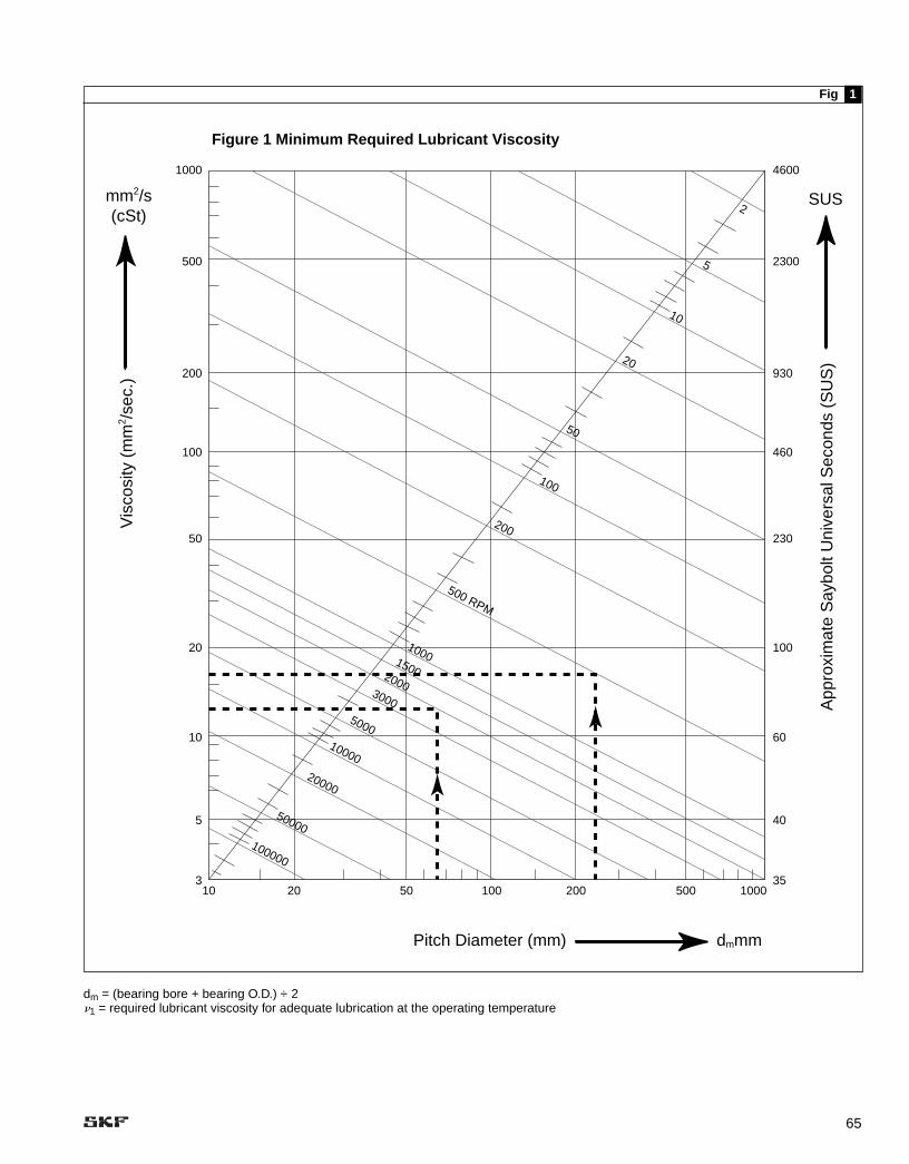
65
1000
500
200
100
50
20
10
5
3
4600
2300
930
460
230
100
60
40
3510 20
100000
50000
20000
10000
3000
5000
1500
1000
500 RPM
200
100
50
20
10
5
2
50 100 200 500 1000
dmmmPitch Diameter (mm)
mm2/s(cSt)
Vis
cosi
ty (
mm
2 /sec
.)
SUS
App
roxi
mat
e S
aybo
lt U
nive
rsal
Sec
onds
(S
US
)
Figure 1 Minimum Required Lubricant Viscosity
2000
Fig 1
dm = (bearing bore + bearing O.D.) ÷ 2�1 = required lubricant viscosity for adequate lubrication at the operating temperature

66
Selection of Oil
The most important property of lubricating oil is the viscosity. Figures and should be used toassure that the viscosity is adequate inan application to insure proper filmforming. Figure shows the minimum required viscosity as a function of bearing size and rotationalspeed. See pages 65 and 67.
The viscosity of a lubricating oil,however, varies with temperature. Itdecreases with increasing tempera-ture. Therefore, the viscosity at theoperating temperature must be used,rather than the viscosity grade (VG)which is based on the viscosity at the internationally standardized refer-ence temperature of 40˚C (104˚F).Figure can be used to determinethe actual viscosity at the operatingtemperature.
Example:
A bearing having a bore diameter of 45mm and an outside diameter of 85 mmis required to operate at a speed of2000 rpm. The pitch diameter dm = 0.5(d + D) = 0.5 (45 + 85) = 65 mm. Asshown in Figure , the intersection ofdm = 65 mm with the oblique line rep-resenting 2000 rpm yields a minimumviscosity required of 13 mm2/s. Now letus assume that the operating tempera-ture is 80˚C (176˚F). In Figure , theintersection between temperature 80˚Cand required viscosity 13 mm2/s isbetween the oblique lines for VG46and VG68. Therefore, a lubricant withthe viscosity grade of at least VG68should be used, i.e. a lubricant of atleast 68 mm2/s viscosity at the stan-dard reference temperature of 40˚C(104˚F).
When determining the operatingtemperature, it should be kept in mindthat the temperature of the oil is usual-ly 3˚ to 11˚C (5˚ to 20˚F) higher thanthat of the bearing housing. For exam-ple, assuming that the temperature ofthe bearing housing is 77˚C (170˚F),the temperature of the oil will usuallybe 80˚ to 88˚C (176˚ to 190˚F).
If a lubricant with higher thanrequired viscosity is selected, animprovement in bearing performance
2
1
2
1
21
(life) can be expected. Contact SKFApplication Engineering for moredetails.
However, since increased viscositycan raise the bearing operating tem-perature, there is frequently a practicallimit to the lubrication improvementwhich can be obtained by this means.Also only solvent refined mineral oilshould be used.
For exceptionally low or highspeeds, for critical loading conditionsor for unusual lubrication conditions,please consult SKF ApplicationsEngineering.
For all calculations, the viscosityshould be expressed in mm2/s (cSt).See Figure for conversion to otherviscosity units.
Note: The previous procedure appliesto solvent refined mineral oils only.
Relubrication IntervalsThe frequency at which the oil must be changed is mainly dependent onthe operating conditions and on thequantity of oil used.
Where oil bath lubrication isemployed it is normally sufficient tochange the oil once a year, providedthe bearing temperature does notexceed 50˚C (120˚F) and there is nocontamination. Higher temperatures or more arduous running conditionsnecessitate more frequent changes,e.g. at a temperature of 100˚C(220˚F) the oil should be changedevery three months.
For circulating oil systems the periodbetween complete oil changes isdependent on how often the oil is circulated over a given period of timeand whether it is cooled, etc. The mostsuitable period can generally only bedetermined by trial runs and frequentexamination of the oil. The same practice also applies to oil jet lubrica-tion. When in doubt, consult machinemanufacturers’ recommendations. In oil mist lubrication, most of the oil is lost, as it is conveyed to the bearingonly once.
Oil Supply Systems
Since oils are liquid, suitable enclosures must be provided to
2b
prevent leakage and they shouldreceive careful consideration.
Oil Bath
A simple oil bath method (➔ fig ) is satisfactory for low and moderatespeeds. The oil level at stand-still must not be higher than the center ofthe lowest ball or roller and, in cases of higher speeds, may lie only 1⁄8” abovethe corner at outer ring face and outer ring sphere. Any static oillevel must be checked only at standstill. A reliable sight-glass gaugeshould be provided to permit an easy check.
Circulating Systems
Circulating oil, by forced feed or othermeans, simplifies maintenance, particu-larly on large machines, and prolongsthe life of the oil where operating condi-tions are usually severe, such as highambient temperatures and steadilyincreasing power inputs and speeds.Entry of oil is best at the center plane ofthe bearing, at the oil groove, near thetop of the housing. Drain for the centerfeed is best done by two drains, one oneach side wall of the housing, leadingdownward immediately outside thehousing. Horizontal drains must beavoided. An alternate method is to havethe inlet on one side, below the horizontal center, and drain from theopposite side of the bearing. The outletshould be larger than the inlet to prevent accumulating too much oil inthe bearing housing.
The amount of oil retained in thehousing is controlled by the location ofthe outlet. For a “wet sump” the oillevel at a standstill must not be higherthan the center of the lowest ball orroller. A reliable sight-glass gaugeshould be provided to permit an easycheck. Where there is extreme heat,the lubricant will last longer if the “drysump” design is used permitting the oilto drain out immediately after it haspassed through the bearing. The outlets are then located at the lowest point on both sides of the housing. It hasbeen found that with this arrangementthe bearings remain cleaner since
3

67
2000
0
2300
1250
900
700
470
350
240
190
140
100
80 60
1000
0
5000
3000
2000
1000 50
040
030
020
015
0
100 75 50 40 30 20 15 10 8 6 5 4 -2
0-1
0
Viscosity Centistokes (mm2/sec.)
010
2030
4050
Tem
pera
ture
, Deg
ree
Cel
sius
Fig
ure
2 V
isco
sity
-Tem
per
atu
re C
har
t
App
roxi
mat
e T
empe
ratu
re C
onve
rsio
ns D
egre
es F
ahre
nhei
tApproximate Viscosity ConversionsSaybolt Universal Seconds (SUS)
6070
8090
100
120
ISO
VG
22
VG 3
2
VG 4
6 (S
AE 2
0)
VG 6
8 (S
AE 2
0)
VG 1
00 (S
AE 3
0)
VG 1
50 (S
AE 4
0)
VG 2
20 (S
AE 5
0)
VG 3
20 (S
AE 5
0)
VG 4
60
ISO
VG
680
150
-414
3250
6886
104
122
140
158
176
194
212
248
302
Fig
2a
Fig
ure
2. V
isco
sity
-Tem
per
atu
re C
har
t V
isco
sity
cla
ssifi
catio
n nu
mbe
rs a
re a
ccor
ding
to in
tern
atio
nal S
tand
ard
ISO
344
8–19
75 fo
r m
iner
al o
ils h
avin
g a
visc
osity
inde
x of
95.
App
roxi
mat
e eq
uiva
lent
SA
E v
isco
sity
gra
des
are
show
n in
par
enth
eses
.

68
2000 70
60
50
40
30
20
1098
7
6
5
4
1000
800
600
500
400
300
200
100
80
60
50
40
30
20
10
8
6
5
4
3
2
300
200
100
90
80
70
60
55
50
45
40
10000
8000
60005000
4000
3000
2000
600
800
1000
1500
500
400
300
200
150
100
80
70
60
50
40
35
32
250W
140W
90W
85W
80W
75W
5W
1
2
3
4
5
6
7
8
8A
1500
1000
680
460
320
220
150
100
68
46
32
22
15
10
7
5
3
2
10W
20W
30W
40W
50W
Viscosities based on 95 VI single-grade oils.ISO grades are specified at 40˚ C. AGMA grades are specified at 100˚F.SAE 75W, 80W, 85W, and 5 and 10Wspecified at low temperature (below -17˚F = 0˚C).Equivalent viscosities for 100˚F and 210˚F are shown. SAE 90 to 250 and 20 to 50 specified at 210˚F (100˚C).
Comparison of various viscosity classification methods
mm2/s at40˚C
mm2/s at100˚C
Kinematicviscosities
Viscosity equivalents
Sayboltviscosities
ISO VG AGMA grades SAE gradescrankcase oils
SAE gradesgear oils
SUS/100˚F SUS/210˚F
Fig 2b

69
Oil outlet for dry sump—both sides
Oil outlet for wet sump (static level) must beat this level on one or both sides
Oil inlet
Fig 4
Figure 4. Pillow Block with Oil Circulation for Felt and Paper Dryers in Paper MachinesThe drain area (one drain each side of the bearing) should be larger than the inlet area to prevent excess oil from accumulating in the hous-ing. Drains can be located to provide a wet sump (static level) or a dry sump. The cross-section of Figure 4 shows a dry sump example tothe left of the bearing and wet sump to the right.
there is little chance of carbonized oilbeing retained in the housing. Whenthe outlets, or drains, are located at thelowest point on both sides of the housing, an arrangement is necessaryto indicate when oil flow is impaired orstopped. Electrically interlocking the oilpump motor with the motor driving themachine can provide this protection.Note that with the SKF bearings thegroove or sphere in the outer ring onhorizontal mountings will always retainsome oil. The bearing will therefore have some oil when it starts to rotate.Figure shows a pillow block with oil4
Fig 3
circulation for felt and paper dryers inpaper machines.
Wick Feed
Wick feed is suitable for extremespeeds as a small quantity of filteredoil is supplied to the bearing.Moreover, there is no risk of the lubricant being churned inside thehousing. However, some attentionmust be given to the wicks and theyhave to be replaced occasionally. Theyshould be dried and thoroughly satu-rated with oil before mounting, in order
to prevent absorption of moisture,which would impair their ability to con-vey lubricant.
Figure shows a wick feed wherethe wick siphons the oil into the bearing.With this arrangement, no wear takesplace but the wicks will continue to feedoil when the machine has stopped.
Figure shows an arrangementwhereby oil is conveyed by a wick by means of capillary attraction to arotating collar or flinger, where it isthrown off by centrifugal force. Thissystem has the advantage of deliveringoil only when it is needed. However, to
10
9
Figure 3. SAF Pillow Block with Oil SumpThe SKF Triple Enclosure Rings are solid rings made with a slip fit on the shaft. The rings can slide along the shaft and adjust their positions with the grooves in the pillow block as governed by the bearing position. Note that the enclosure drains return to the sump belowthe oil level. This is to prevent oil in mist or splash form from entering the enclosures through these returns.
OilLevel

70
Fig 5 Fig 6
Figure 5. Oil Lubrication of Gears with Small Pitch DiameterThe lubricant squeezed out sideways from the mesh may carry par-ticles worn off the teeth. As foreign matter causes noise and short-ens bearing life, a baffle (a) or shield (b) is arranged to deflect thespray. The oil mist inside the housing is generally sufficient for lubri-cation of the bearings.
Figure 6. Oil Spray on Fan Motor BearingsThe oil is conveyed to the tapered flinger by an oil ring which dipsinto the oil bath. An important feature of this application is that theair pressure on both sides of the bearing and enclosures is equal-ized by connecting ducts. This prevents leakage of the lubricantwhen the housings are located in an air stream.
function, the wick must be in contactwith the rotating flinger.
Oil Mist from Separate Mist Generator
This method consists of a mixture ofair and atomized oil being supplied tothe bearing housing under suitablepressure. The oil mist is formed in anatomizer. Several manufacturers offersuitable designs and can recommendsystems, capacities, and operatingtemperature and pressures to assuremaintaining the required oil viscosity, �,at the bearings’ rolling contacts.
The air, charged with a mist of oil, isintroduced in the housing between thebearings so that the air will passthrough the bearings before escapingthrough the housing enclosures orvents. The air from the supply line firstpasses through a filter then through areduction valve, which reduces the linepressure to a suitable value. It thenpasses through an atomizer, where theoil mist is formed. It is important thatthe air be sufficiently dry, which some-times makes it necessary to use adehumidifier before the air is filtered.
This method of lubrication hasproven very effective in reducing theoperating temperature, not so much byair cooling as by the flow of air prevent-ing excess oil from accumulating in thebearing. Since the air under pressurein the housing escapes through thehousing enclosures or vents, theentrance of moisture and grit is retarded. In addition, oil mist lubrication continuously supplies only clean, freshoil to the bearings. The two factorscontribute to full life expectancy.Because the bearings require very little lubricant, the oil consumption iscomparatively small.
Air/Oil Lubrication
The air/oil method of lubrication usescompressed air to transport a very precise amount of lubricant directly to abearing. In contrast to oil mist methods, the air/oil method involves no atomiza-tion of the air and oil. Generally, all airoil systems operate on the same principle. A continuous supply of compressed air is used to transport a predetermined amount of oil to a
specific point. Oil is metered into the airstream of the supply lines to the bearing housings at set time intervals,monitored by a programmable con-troller. The oil coats the inside of thesupply lines and “spirals” / “creeps” inthe direction of the air flow. Through aphenomenon known as the “wall attach-ment effect,” the oil is transported alongthe inside wall of the feed line by themovement of the air, but never mixeswith the air. Figure shows a typicalair/oil system configuration.
Both the oil mist and air/oil methodsof lubrication offer the ability to buildand maintain internal bearing pressures, which help to repel contami-nants. However, when used in appropri-ate applications, the air/oil methodoffers significant advantages. For example, higher base oil viscosity canbe more effectively used with the air/oilsystem. Also, the system does not ventoil mist into the environment. Finally, ituses a lower volume of oil, so it is morecost-efficient.
11
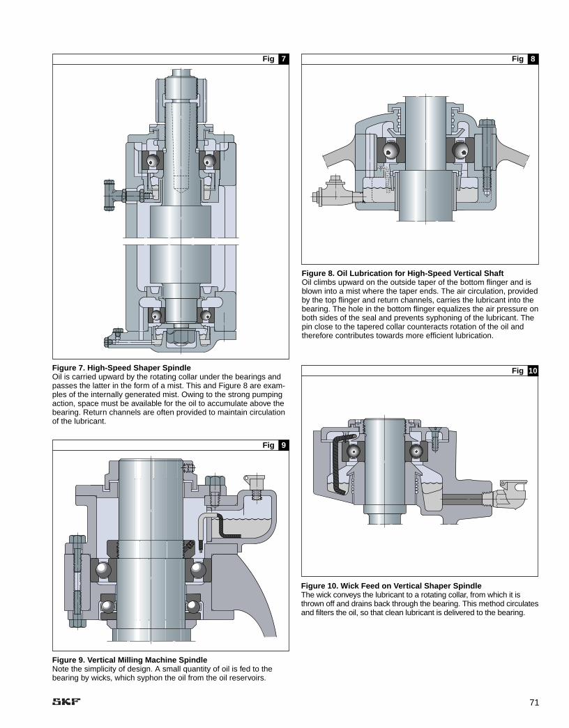
71
Fig 9
Fig 10
Figure 9. Vertical Milling Machine SpindleNote the simplicity of design. A small quantity of oil is fed to thebearing by wicks, which syphon the oil from the oil reservoirs.
Figure 10. Wick Feed on Vertical Shaper SpindleThe wick conveys the lubricant to a rotating collar, from which it isthrown off and drains back through the bearing. This method circulatesand filters the oil, so that clean lubricant is delivered to the bearing.
Fig 7 Fig 8
Figure 7. High-Speed Shaper SpindleOil is carried upward by the rotating collar under the bearings andpasses the latter in the form of a mist. This and Figure 8 are exam-ples of the internally generated mist. Owing to the strong pumpingaction, space must be available for the oil to accumulate above thebearing. Return channels are often provided to maintain circulationof the lubricant.
Figure 8. Oil Lubrication for High-Speed Vertical ShaftOil climbs upward on the outside taper of the bottom flinger and isblown into a mist where the taper ends. The air circulation, providedby the top flinger and return channels, carries the lubricant into thebearing. The hole in the bottom flinger equalizes the air pressure onboth sides of the seal and prevents syphoning of the lubricant. Thepin close to the tapered collar counteracts rotation of the oil andtherefore contributes towards more efficient lubrication.

72
COMPRESSED AIR
METERED OILSUPPLY
(cc/HOUR)
OIL FILM
AIR/OIL STREAM
Fig 11
Grease Lubrication
Rolling bearing greases are usually a suspension of oil in a soap or non-soap thickener, plus protective addi-tives. When moving parts of a bearingcome in contact with the grease, asmall quantity of oil will adhere to thebearing surfaces. Oil is, therefore,removed from the grease near therotating parts. The oil that is picked up by the bearing is gradually brokendown by oxidation or lost by evapora-tion, centrifugal force, etc. Bleeding of the grease should, therefore, takeplace to continually supply a quantity of oil sufficient for satisfactory opera-tion. In time, the grease will oxidize or the oil in the grease near the bear-ing will be depleted. Relubrication isthen necessary.
The Ball and Roller BearingEngineers’ Committees of the American Bearing ManufacturersAssociation, Inc. (ABMA) has been,over a period of years, undertaking lab-oratory and field research in an effort toobtain a solution to the many problemsthat are faced by rolling bearing usersin obtaining suitable greases for lubri-cating bearings. In as much as thebearing manufacturers have no controlover the manufacture of greases, theycannot be expected to guarantee theirperformance under all conditions. Theguide which follows has been devel-oped from practical experience andcareful analysis and its only purpose isto aid the rolling bearing user in theselection of the proper lubricant for the
operating conditions of a particularapplication. The bearing user willappreciate that some lubricants whichconform to this guide may not be suit-able for all applications, and that somegreases that do not conform maysometimes be satisfactory. It is recom-mended that the bearing user consultwith the bearing manufacturer and thegrease supplier to determine the lubri-cant that will be most suitable for theparticular application, especially fortemperatures below –29˚C (–20˚F) and above 121˚C (250˚F).
There is a trend toward developing agrease sometimes designated as an “all purpose lubricant” coveringextremes of temperature. However, untilsuch a grease has been produced andproven by exhaustive tests both in thelaboratory and in the field, it will not berecognized in this guide. It has long been felt that the actual temperature of thebearing while running is the most criticalfactor to be considered in choosing agrease, and for this reason SKF showsthe five most frequently encounteredgrease types and their satisfactory running temperature ranges.
Grease life is not shown since suchfactors as temperature, speed, load,humidity, type of service and frequen-cy of lubrication would all have to be considered. In applications where elevated temperature, high speed,severe dirt, high humidity or otherextreme conditions are encountered,particularly with open type bearings,accelerated deterioration of the greasemay ensue. In such cases periodic
inspection during the first few weeks of operation will provide the best deter-mination of the required frequency of relubrication.
On the other hand, relubrication of sealed bearings which have been provided with approved greases in the proper amount is not generally considered advisable.
All grease shall be free from dirt, abrasive matter, fillers, excessive amountof moisture, free acid or free alkali.
Grease Classification
1. Group I — General Purpose Greases that are expected to giveproper lubrication to bearings whoseoperating temperatures may vary from–40˚C to 121˚C (–40˚F to 250˚F).
2. Group II — High TemperatureGreases that are expected to giveproper lubrication to bearings whoseoperating temperatures may varyfrom -18˚C to 149˚C (0˚F to 300˚F).
3. Group III — Medium TemperatureGreases that are expected to giveproper lubrication to bearings whoseoperating temperatures may varyfrom 0˚C to 93˚C (32˚F to 200˚F).
4. Group IV — Low TemperatureGreases that are expected to giveproper lubrication to a bearingwhose operating temperature maygo as low as –55˚C (–67˚F) or ashigh as 107˚C (225˚F).
Figure 11. Typical air/oil configuration
The oil is transported along the inside wall of a pipe, usinga phenomena called the "wall attachment effect".

73
5. Group V — Extreme HighTemperature Greases that are expected to giveproper lubrication for comparativelyshort periods of time where bearingoperating temperature may be ashigh as 232˚C (450˚F).
These five groups of greases coverapplications where the lubrication is not affected by extremely heavy loads,high speeds or excessive humidity. Thetabulation of test requirements whichfollows shows those characteristicsneeded to meet the functional require-ments of good rolling bearing greases.
The five groups of greases previously listed along with their testrequirements in general apply to bothball and roller bearing greases. Usuallyroller bearing lubrication requires asomewhat softer grease, and a mini-mum ASTM worked penetration of 300is often specified. All of the otherrequirements such as oxidation stability, dropping point and dirt countapply to greases for roller bearing aswell as ball bearing applications.
In greasing rolling bearings the useof high pressure equipment is not onlyunnecessary but is actually undesir-able unless used with great care. High pressure may damage the bear-ings, cause unnecessary loss ofgrease, create a danger of overheatingdue to overgreasing and produceunsightly conditions around the bear-ing. A ball or roller bearing in mostapplications is assured of adequatelubrication if the level of grease ismaintained at 1⁄3 to 1⁄2 of the volume of the bearing housing space. Anygreater amount will, as a rule, be dis-charged by the seals and be wasted.
There may exist applications whereit will be necessary to grease the bearings with either more or less thanthe recommended 1⁄3 to 1⁄2 of volume. In applications where the speed is highor low torque is a requirement thebearings may be lubricated with a verysmall amount of grease. Similarly inapplications where the speed is verylow and the bearing is exposed toexcessive amounts of dirt or moisturethe bearing may be packed nearly full.
Greases to be used in miniature bear-ings and instrument bearings may requirea lower dirt maximum per cubic cm ratiothan listed in the accompanying table.
Methods of Testing
TestRequirements Method
ASTM Penetration Method ASTM D-217Normal Worked
Oxidation Method ASTM D-942
Low Temperature Method ASTM D-1478Torque
Water Resistance Method ASTM D-1264
Dropping Point Method ASTM D-566
Evaporation Method ASTM D-972
Dirt Method Federal Test Method Standard No. 791-B Method 3005.3
Consistency, Method ASTM D-217Stability
Abrasive Matter Method ASTM D-1404
Free Acid and Method ASTM D-128Free Alkali
Fillers Method ASTM D-128
Moisture Method ASTM D-128
Test Requirements
Tests Group I Group II Group III Group IV Group V
ASTM Penetration 250 to 350 200 to 300 220 to 300 260 to 320 250 to 310Normal Worked1
Oxidation 10# max. drop 10# max. drop 10# max. drop 5# max. drop 5# max. dropin 500 hours in 500 hours in 500 hours in 500 hours in 100 hours
at 121˚C (250˚F)
Low Temperature 1 rev. in max. of — — 1 rev. in max. of 1 rev. in max. ofTorque 10 sec. at –40˚C 5 sec. at –55˚C 10 sec. at –40˚C
(–40˚F) (–67˚F) (–40˚F)
Water Resistance 50% max. loss - 50% max. loss 20% max. loss 50% max. loss
Dropping Point 149˚C min. (300˚F) 177˚C min. (350˚F) 149˚C min. (300˚F) 149˚C min. (300˚F) 232˚ C min. (450˚F)
Evaporation — — — 1.5% max. in 22 4.0% max. in 22hours at 121˚C hours at 204˚C(250˚F) (400˚F)
Dirt Max. Particles 5000/5-20 microns Same as Group I Same as Group I Same as Group I Same as Group Iper cubic cm 2000/20-50 microns
50/50-75 micronsNone over 75microns
Consistency Penetration shall Penetration shall Penetration shall Penetration shall Penetration shallStability: max. not increase more not increase more not increase more not increase more not increase moreASTM than 100 points than 100 points than 100 points than 100 points than 100 pointsPenetration after and in no case be and in no case be and in no case be and in no case be and in no case be100,000 strokes more than 375 more than 350 more than 350 more than 375 more than 375
1National Lubricating Grease Institute Code — No. 0: 355-385; No. 1: 310-340; No. 2: 265-295; No. 3: 220-250; No. 4: 175-205

74
mixing greases of different soapbases. Since the rust preventive inwhich SKF bearings are packed is apetroleum product, the only occasionfor removing it is when the bearing isto be lubricated with special lubricants.
Operating Conditions
The amount of oil needed by the bear-ing depends of course, on operating conditions — particularly temperature.Since a temperature rise of 8˚ to11˚C(14˚ to 20˚F) can double the rateof oxidation, the lubrication problem atthe higher temperatures requires morecareful consideration. It would howeverbe erroneous to conclude that a greasesuitable for a high temperature wouldalso be successful at low temperatures.In all probability, it would be too hard to supply the oil required. On the otherhand, a grease which is too soft mayhave a tendency to flow out of a hotapplication. The selection of the mostsuitable consistency of a grease isdependent upon the bearing design aswell as its orientation.
In Figures , , and further reference is made to this condition.
It is accordingly advisable to have a competent Lubrication Engineercheck all applications before taking any action which is not supported by available experience.
141312
considered good general purposegreases, while calcium, lithium, andbarium soap greases and the non-soap greases are often used whenwater resistance is necessary.However, calcium base greases arelimited to lower operating tempera-tures. The fluids used in compoundingthese greases may vary in viscosityfrom 10 mm2/s at 38˚C (60 SUS at100˚F) to over 431 mm2/s(2000 SUS).Special synthetic oils are used to produce greases that can be used atextremely low and/or extremely hightemperatures. Be careful to avoid
Greases considered satisfactorylubricants for rolling bearings are combinations of soap or non-soapthickening agents, mineral oil, and inmany cases ingredients necessary toimpart special properties to the grease.Soaps such as sodium, calcium, alu-minum, lithium, barium, and non-soapthickening agents such as silica andchemically treated clays are generallyused. Rust and oxidation inhibitors andtackiness additives are often added toimpart properties not normally presentin the grease. Sodium and mixed sodium-calcium soap greases are
Fig 12 Fig
Figure 12. Radial Bearings on Horizontal ShaftsSince the machined retainer in (a) presents flat surfaces to the surrounding lubricant, a stiff grease may soon leave the interior of the bearing dry. The lubricant must therefore, in this case, be rather soft at the operating temperature. A somewhat stiffer grease might,however, be satisfactory with (b) as the interior is more accessible. The position of (c) isintermediate in this respect.
Figure 13. Angular Contact Ball Bearingon Horizontal ShaftAngular contact bearings tend to pump thelubricant from the side (a) to (b). A grease ofsoft consistency would pass right throughthe bearing if applied at (a), whereas, a stiffgrease would be more satisfactory if appliedfrom the same side. On the other hand, asoft grease would be more desirable ifapplied at side (b), since a hard greasewould channel and leave the bearing dry.
a
Fig 14
Figure 14. Deep Groove Ball Bearings on Vertical ShaftOn vertical applications where the grease is admitted above the bearing a hard grease isrequired so that it remains in the bearing (a). Where the grease is resting on a plate, as in(b), a softer consistency is required as otherwise no lubricant would seep into the bearing.
13
b
(a) Cylindrical Roller Bearing
(b) Deep Groove Ball Bearng
(c) Spherical RollerBearing
(a) (b)

75
Lubrication and Maintenance
Relubrication
Rolling bearings have to be lubricatedif the service life of the grease used is shorter than the expected servicelife of the bearing. Relubrication should always be undertaken at a time when the lubrication of the bearing is still satisfactory.
The time at which relubricationshould be undertaken depends onmany factors. These include bearingtype and size, speed, operating tem-perature, grease type, space aroundthe bearing and the bearing environ-ment. The SKF relubrication intervalsare defined as the time period, at theend of which 99% of the bearings arestill reliably lubricated, and representL01 grease lives. The L10 grease livesare approximately twice the L01 lives.
The information given in the followingdoes not apply to applications wherewater and/or solid contaminants can pen-etrate the bearing arrangement. In suchcases it is recommended that the greaseis frequently renewed in order to removecontaminants from the bearing.
Relubrication Intervals
The relubrication intervals tf for normaloperating conditions can be read off as a function of bearing speed n andbore diameter d of a specific bearingtype from Figure . The diagram isvalid for bearings on horizontal shaftsin stationary machines under normalloads. It applies to good quality lithiumbase greases at a temperature notexceeding +70˚C(+160˚F). To takeaccount of the accelerated ageing ofthe grease with increasing temperatureit is recommended that the intervalsobtained from the diagram are halvedfor every 15˚C(27˚F) increase in bear-ing temperature above +70˚C(+160˚F),remembering that the maximum operating temperature for the greaseshould not be exceeded. The intervalsmay be extended at temperatureslower than +70˚C(+160˚F) but as operating temperatures decrease thegrease will bleed oil less readily, and at low temperatures an extension ofthe intervals by more than two times
15
is not recommended. It is not advisableto use relubrication intervals in excessof 30,000 hours. For bearings on verti-cal shafts the intervals obtained fromthe diagram should be halved.
It is also necessary to lubricate more frequently in applications wherethere is a risk of heavy contamination, e.g.: bearings in papermaking machinery,where housings are washed with water.Large roller bearings having a bore diam-eter of 300 mm and above, adequatelubrication will be obtained only if thebearing is more frequently relubricatedthan indicated by the diagram, and thelines are therefore broken. The greasequantity to be supplied can be obtainedfrom the equation below for applicationswhere conditions are otherwise normal,i.e. where external heat is not applied (recommendations for grease quantitiesfor periodic relubrication are given in thefollowing section).
Gk = (0.3 ...0.5) D B x 10–4
where
Gk = grease quantity to be continuously supplied, g/h
D = bearing outside diameter, mmB = total bearing width (for thrust
bearings use total height H),mm
Relubrication procedures
One of the two procedures describedbelow should be used, depending onthe relubrication interval tf obtained:
— If the relubrication interval is shorter than 6 months, then it is recommended that the grease fill in the bearing arrangement bereplenished (topped up) at intervalscorresponding to 0.5 tf; the com-plete grease fill should be replacedafter three replenishments.
— When relubrication intervals arelonger than 6 months it is recom-mended as a rough guideline thatall used grease be removed fromthe bearing arrangement andreplaced by fresh grease.
Replenishment
By adding small quantities of freshgrease at regular intervals the used
grease in the bearing arrangement willonly be partially replaced. Suitable quan-tities to be added can be obtained from
Gp (g) = .005 x D (mm) x B (mm)
D (in) x B (in)Gp (oz) = —————————
10
where
Gp = grease quantity to be addedwhen replenishing
D = bearing outside diameterB = total bearing width (for thrust
bearings use total height H)
Grease Supply Systems
Housings without Grease Fittings
For light and medium service, such as line shafts, the original supply ofgrease will usually last from one to two years or even a longer time atlower ambient temperature. It is,accordingly, advisable to omit greasefittings to discourage over-greasing.The old grease should be removedduring overhauls and replaced by newgrease, which should be worked intothe available space in the bearing byhand. ABMA recommends from 1⁄3 to 1⁄2of the volume in the housing should be filled with grease for normal appli-cations. An over-supply would onlyresult in churning and breakdown of the lubricant.
Needless to say, care should betaken to keep the bearing and lubricant clean.
Housings with Grease Fittings
The original filling, and subsequentadditions of small amounts of greaseafter cleaning at major overhauls,should be made as indicated previously.
Adding of lubricant close to the bear-ing can be effected in several ways.
Figure shows a design whichcan easily be adapted for this purpose.The lubricant is added using a greasegun at the bottom of the housing, closeto the outer ring. The radially placedribs inside the left-hand end cover tendto deflect the new grease into the bearing without the undesirable effectof first filling the entire space in the
16

76
1500
025
000
3000
025
000
2000
0
1500
0
1000
0
5000
4000
3000
2000
1500
1000 50
0
400
300
200
150
100
100
cb
aL 0
1 G
reas
e Li
fe
n r/
min
Relubrication interval tf operationing hours
23
45
67
89
2
500
420
360
280240
200160
12010080
60
40
20
d =
10 m
m
34
56
78
9
1000
Sca
le a
:S
cale
b:
Sca
le c
: ra
dial
bal
l bea
rings
cylin
dric
al r
olle
r be
arin
gs, n
eedl
e ro
ller
bear
ings
sphe
rical
rol
ler
bear
ings
, CA
RB
TM to
roid
al r
olle
r be
arin
gs, t
aper
rol
ler
bear
ings
, thr
ust b
all b
earin
gs;
cylin
dric
al r
olle
r th
rust
bea
rings
, nee
dle
rolle
r th
rust
bea
rings
, sph
eric
al r
olle
r th
rust
bea
rings
(0.
5tf);
cr
osse
d cy
lindr
ical
rol
ler
bear
ings
with
cag
e (0
.3t f)
; fu
ll co
mpl
emen
t cyl
indr
ical
rol
ler
bear
ings
(0.
2tf)
1000
020
000
2000
0
1500
0
1000
0
8000
6000
4000
3000
2500
2000
1500
1000 75
0
500
400
300
200
150
100 75 50
1000
060
00
4000
2000
1000 80
060
050
040
0
300
250
200
150
100 80 60 50 40 30 20 15 10
bear
ing
bore
dia
met
er (
mm
)d
:
Fig
15
Fig
ure
15.
See
Pag
e 81
for
an E
xam
ple
of
Ho
w t
o U
se T
his
Ch
art.
See
pg
. 75
(Lu
bri
cati
on
an
d M
ain
ten
ance
) fo
r ex
pla
nat
ion
of
L01
.

77
end-cover. These ribs also prevent thegrease from being carried around orworked by the rotating shaft, therebykeeping the temperature down andpreventing grease leakage. The end-cover on the right-hand side providesample space to receive the old greasewhich has passed through the bearing.The cover is split to facilitate removalof the old grease at major overhauls.
Another method which can be usedfor small and medium size bearings isto force out the old grease with thenew. The housing should have a largedrain, located on the side opposite the grease fitting, to force all grease to pass through the bearing.
Before adding new grease, makesure that the grease fitting is clean.Clean out any grease which may havecaked in the drain hole, so the oldgrease may be easily expelled. Whenadding grease, remove the drain plugand force the new grease through thefitting while the shaft is rotating.Continue forcing in new grease until itstarts to come out of the drain. Theshaft should then be allowed to rotatefor about 20 minutes before replacingthe drain plug, to give the bearing achance to expel the excess grease.
Observe cleanliness at all times, what-ever method is used, and be sure the newlubricant is clean. Contaminated lubricantwill reduce the life of the bearing.
Comparing both methods, the firstcalls for more skill if the dangers of over-greasing are to be avoided, buthas the advantage of being applicableto large bearing sizes, while the latterlends itself readily to small bearings.With large bearings the pressure of the grease gun may not suffice to drivethe old grease through the drain to the extent desired. Consequently, the bearings might be left in an over-greased state conducive to hot running.
Grease Chamber Lubrication
The arrangement shown in Figure employs the use of a double-shieldedbearing, which has been prelubricated.One side of the bearing housing ispacked full of an appropriate grease by the usual grease gun method. Seegrease classifications page 72. Additionof lubricant to the original supply takesplace by seepage of oil from the
17
grease as well as a small amount ofgrease being forced though the clear-ance in the shield. Care should betaken to ensure that the proper typeand amount of grease is injected. See replenishment on page 75. Thismethod does not eliminate the need forcare in avoiding overgreasing and itsconsequent overheating and prematurefailure. Using double-shielded bearingsnot only helps prevent over-greasingbut also protects the bearing from dustand foreign matter at assembly, orwhenever the bearing is exposed.Using the double-shielded bearingdoes not permit the elimination of theusual housing enclosures.
Prelubricated ball bearings withoutprovisions for adding more grease areused in domestic appliances and othermachines where the total number ofservice hours is small. It should bekept in mind that the life of these“greased for life” bearings may be limited to the time the grease will last.
Grease Quantity Regulator
The grease chamber method describedabove and the frequency of relubrica-tion needed as relative speeds increaseboth add to the potential for greasebuildup in a housing. SKF developed aGrease Quantity Regulator design thatprohibits over-greasing regardless ofthe frequency of lubrication needed.The Regulator is shown adapted to a horizontal application in Figure and to a vertical application in Figure . The Regulator consists of a regulating disc, which turns with the shaft and maintains a small radial or tapered gap with a stationary part.
If the grease quantity in the bearinghousing does not exceed a limit suitablefor that bearing and housing, the greaseat both sides of the bearing remainsnearly stationary and the temperatureremains normal. This is the greasereserve from which oil is supplied to thebearing when bearing temperaturebegins to increase. If the grease quantityis increased beyond the stable limit, partof the grease is thrown about by therotating bearing and is thrown againstthe Regulator and ejected through thedrain. The process continues until freshgrease is no longer injected and theoperating quantity becomes stable again.
19
18
Fig 16
Figure 16. Roller Bearing Arrangementfor Large Electric Motor
Fig 17
Figure 17. Grease Chamber forElectric MotorThe space between the shield in thebearing and the end-cover is packedwith suitable grease.

78
Comparative Advantages of Oil and Grease
Advantages of oil
1. Oil is easier to drain and refill.This may be more desirable forapplications requiring frequentlubricating intervals.
2. The correct amount of lubricantis more easily controlled.
3. Oil lends itself more readily to thelubrication of all parts of a machine.
4. Oil lends itself to applicationswith higher temperatures andhigher operating speeds.
Advantages of grease
1. Maintenance work is ordinarilyreduced since there are no oil lev-els to maintain, and addition of newlubricant is required less frequently.
2. Grease in proper quantity ismore easily confined to thehousing. Design of enclosurescan therefore be simplified.
3. Freedom from excess leakage isreadily accomplished in food,textile and chemical industries,and where contamination ofproducts must be avoided.
4. Grease improves the sealingefficiency of enclosures.
A major feature of relubricating bearings with grease quantity regulatorsis that the inlet is located on the side of the bearing opposite the Regulator.The interior of the cover on the inlet side should have ribs dividing theinboard space into chambers to reducechurning. The chambered cover andregulator disc combine the advantagesof introducing fresh grease immediatelyto where it is needed, effective purgingof old grease, and freedom from thedangers of over-greasing.
High Temperature Applications
Where heat is generated in the bearingsonly, temperature can usually be keptwithin reasonable limits by means of asuitable selection and quantity of lubri-cant. The contrary applies to cases where
heat also comes from outside sources,such as in hot gas fans, dryers, and soforth. Under such conditions, somemethod of cooling is usually necessary toavoid excessive bearing temperaturesand premature failure of lubrication. Thefollowing are some of the methods usedfor decreasing the bearing temperature:
1. Auxiliary cooling disc for dissipation of heat conducted through the shaft (➔ fig ).
2. Water-jacketing the end-covers willalso serve to cool the oil. Hereagain, it is essential to shut off thecooling water when the machine isstationary in order to prevent con-densation. The bearing housing extending around the outer ringshould not be water-jacketed, sincethis will introduce complications inmaintaining the desired fit of theouter ring in the housing.
3. Circulation of the oil can also be usedto advantage, provided that the oil iscooled and filtered. Settling tanks arealso used to permit any sludge for-mation or other foreign matter to set-tle out. As previously pointed out, theoil should be permitted to drain out asquickly as possible at the lowest pointon both sides of the housing after having passed through the bearing.Thus, unnecessary heating of the oiland the settling of sludge inside thehousing are prevented.
Minimum Friction Applications
The friction of SKF ball and roller bearings is, in most cases, too small
20
to merit any attention. There are, how-ever, applications such as hand-drivenappliances, instruments, etc., wherefriction must be kept to a minimum.Friction is due not only to the bearingdesign but also the quantity of lubri-cant used. Because of the manyexacting requirements that are neces-sary if friction is to be held to a mini-mum, it is impossible to treat this sub-ject in a general way. Applications ofthis kind should therefore be givenindividual consideration. SKFApplications Engineering welcomesthe opportunity to make use of experience which has been gained in this field.
Protection Against Moisture
No rolling bearing lubricant has beendeveloped which will completely protecta bearing against moisture. However,rolling bearings are frequently used withsuccess where moisture is present. Thedesign of enclosures and lubricationsystems requires careful consideration.Selection of the lubricant is important tominimize effects of some moisture entry.
Compounded oils are more waterrepellent than straight mineral oils and are therefore better able to keepmoisture from the bearing surfaces. Ifthe oil is permitted to oxidize, it will bemore destructive to the bearing sur-faces when moisture is present.
Lithium-base greases are water-repellent but the grease mustcompletely cover the bearing to protectit. Water-repellent grease is useful also in improving the efficiency of labyrinth seals.
Fig 18 Fig 19
Figure 18. Grease Quantity RegulatorHorizontal Shaft
Figure 19. Grease Quantity RegulatorVertical Shaft

79
Protection of Idle Machinery
Equipment which is idle must be set in motion periodically to spread thelubricant over all bearing surfaces.
Suitable intervals depend on ambi-ent conditions. For storage, assembledbearings should be cleaned andpacked full with petrolatum or othersuitable anti-rust agents, according to the advice of a reputable supplier.However, storage grease must beremoved thoroughly and the properamount of a suitable lubricant appliedbefore operation.
Cleaning
All lubricants have a tendency to deteriorate in the course of time, but at a greatly different rate. Therefore,sooner or later, it will be necessary to replace the old lubricant with new.
Oils and greases should be removedin the early stages of deterioration sothat removal does not become unnec-essarily troublesome. Oils can bedrained and the bearing flushed andwashed, preferably with some solvents,kerosene or even with light oil. Thesolution should then be drained thor-oughly and the bearing and housingflushed with some hot, light oil andagain drained before adding new lubri-cant. Lighter petroleum solvents maybe more effective for cleaning but areoften objectionable, either because offlammability or because they may havea tendency to become corrosive, par-ticularly in the presence of humidity.
A grease is also more easily replen-ished in early stages of deterioration,for instance, by displacement with newgrease, if the housing is designed sothat this can be done.
Bearings which are dismantled are,of course, much more easily cleanedthan bearings which must stay assem-bled in equipment. Solvents can thenbe used more freely for cleaning.
Badly oxidized oil and grease, however, need a very thorough treat-ment for their removal; ordinary sol-vents are usually not satisfactory.
The following methods for cleaningunshielded bearings, as suggested byABEC (Annular Bearing Engineers’Committee) are recommended.
1. Cleaning unmounted bearings whichhave been in service
“Place bearings in a basket and suspend the basket in a suitable container of clean, cold petroleum solvent orkerosene and allow to soak, preferablyovernight. In cases of badly oxidizedgrease, it may be found expedient tosoak bearings in hot, light oil at 93˚ to116˚ C (200˚ to 240˚F), agitating thebasket of bearings slowly through theoil from time to time. In extreme cases,boiling in emulsifiable cleaners dilutedwith water will usually soften the con-taminating sludge. If the hot emulsion solutions are used, the bearings shouldbe drained and spun individually untilthe water has completely evaporated.The bearings should be immediatelywashed in a second container of cleanpetroleum solvent or kerosene. Eachbearing should be individually cleanedby revolving by hand with the bearingpartly submerged in the solvent...turning slowly at first and working with a brush if necessary to dislodge chipsor solid particles. The bearings may bejudged for their condition by rotating byhand. After the bearings have beenjudged as being clean, they shouldimmediately be spun in light oil to completely remove the solvent . . .coated with preservative if they are notto be reassembled immediately and
wrapped at once in clean oilproof paperwhile awaiting reassembly.
“The use of chlorinate solvents ofany kind is not recommended in bear-ing cleaning operations because of therust hazard involved. Nor is the use ofcompressed air found desirable inbearing cleaning operations.”
2. Cleaning of Bearings as Assembledin an Installation
“For cleaning bearings without dis-mounting, hot, light oil at 93˚ to 116˚ C(200˚ to 240˚F) may be flushed throughthe housing while the shaft or spindle is slowly rotated. In cases of badly oxidized grease and oil, hot, aqueousemulsions may be run into the hous-ings, preferably while rotating the bearings until the bearing is satisfactorilycleaned. The solution must then bedrained thoroughly, providing rotation ifpossible, and the bearing and housingflushed with hot, light oil and againdrained before adding new lubricant. Insome very difficult cases an intermedi-ate flushing with a mixture of alcoholand light mineral solvent after the emulsion treatment may be useful.
“If the bearing is to be relubricatedwith grease, some of the fresh greasemay be forced through the bearing topurge any remaining contamination.This practice cannot be used unless
Held End
Free End
Oil————Level
Fig 20
Figure 20. Heat-Dissipating DiscThe disc is located between the bearing and the source of heat, so that any heat travelingthrough the shaft towards the bearing will be dissipated by radiation. The disc is sometimesprovided with vanes to improve the efficiency by circulating the air.

80
there are drain plugs which can beremoved so that the old grease may be forced out. Also, bearings should be operated for at least twenty minutesbefore drain plugs are replaced, asexcess lubricant will cause seriousoverheating of the bearing.”
3. Oils Used for Cleaning
“Light transformer oils, spindle oils, orautomotive flushing oils are suitable forcleaning bearings, but anything heavierthan light motor (SAE 10) is not recom-mended. An emulsifying solution madewith grinding, cutting or floor cleaningcompounds, etc., in hot water, hasbeen found effective. Petroleum sol-vents must be used with the usual pre-cautions associated with fire hazards.”
WARNING: Follow the Material SafetyData Sheet (MSDS) safety instructionsincluded with the solvent you use toclean bearings.
CARBTM Toroidal Roller BearingLubrication
Selection of grease
Grease for CARB toroidal roller bear-ings is selected on the same basis asfor other rolling bearings. The greaseshould normally have a consistency of 2 or possibly 3 to the NLGI Scale andshould be rust inhibiting and of goodquality. The most important factors to beconsidered when selecting a grease are
• operating temperature• speed• vertical or horizontal shaft
The shaft must be clean
Mount the bearing on the shaft
Grease the bearing
Figure 21. Mounting procedure
Fig 21
1. Bearings with cage 2. Full complement bearings (without cage)
Fig 22
Figure 22. How to grease CARB toroidal roller bearings
1. Bearings with cageCARB has a relatively large free vol-ume available for grease. If the bear-ing is run at relatively high speed(greater than �75% of catalog speedrating for grease) then there is achance that the temperature will beelevated with a full pack of grease.
The recommendation is thereforeto only fill the space between inner
ring and cage when initially greasing the bearing for high speed applications.
For low or moderate speeds, the bearing may be fully packed with grease.
2. Full complement bearingsAll free space in the bearing shouldbe packed with grease.

81
Grease nipple
Grease escape hole
Care should be taken when using a grease gun operated by pressurized air.The seals may be damaged by the pressure.
Figure 23. Grease lubrication of CARB toroidal roller bearing
Fig 23• operating conditions such as vibration
• bearing type and size• bearing load• full complement or caged bearing
The viscosity of the base oil of agrease partly determines the thicknessof the lubricant film in the rolling contact.
Applying the grease
On delivery, CARBTM toroidal rollerbearings are coated with a rust inhibit-ing compound. There is no need toremove this.
Generally a CARB bearing is firstgreased when it has been mounted inorder to minimize the risk of contami-nation. Only in cases where it is impos-sible to apply the grease evenly to thebearing should the grease be appliedbefore the bearing is mounted.
The application of grease to CARBbearings is shown in figs ➔ and .2221
2
15000100006000
4000
2000
1000
600500400
300250200
150
100
80
605040
30
20
15
103
d = 10 mm
20
406080100120
160
200
280
360
420
500
4 5 6 7 8 9 2
1000100 10000 20000
3 4 5 6 7 8 9
240
Rel
ubric
atio
n In
terv
al t f
oper
atio
ning
hou
rs
Example C 2220 KThe bearing has a bore diameter of d = 100 mm and is to rotate at 1000 r/min.The operating temperature varies between50 and 70°C (122° and 160°F). What is the recommended relubrication interval?
A line from 1000 r/min on the x axis is followed until it meets the curve for 100 mm bore. A line at right angles is thenfollowed to the y axis where the value is found to be 2000 h. Thus the relubrication interval is 2000 operating hours.
L01 grease life
n r/min
Fig 24
Figure 24. Relubrication diagram

82
Excess grease isthrown from therotating disc into agroove in the endcover of the housing
Housing end cover
Rotating disc
Fig 26
Figure 26. Grease valve
How to lubricate CARBTM toroidal roller bearings
Since CARB bearings have one row of rollers they can only be lubricated fromthe side. The housing should be fittedwith a grease nipple at the side oppositeto the lock nut (if they are mounted on anadapter sleeve). If they are to be fre-quently relubricated it is advisable for the housing base to have a grease escapehole at the side of the bearing opposite to the grease nipple, see ➔ fig .
Experience gained with all roller bear-ings indicates that a first relubricationafter a few days of operation is verybeneficial, and may even be a prerequi-site if the expected relubrication intervalis to be attained when operating speedsare high. For this first relubrication halfof the normal quantity recommended forregular relubrication will be sufficient.
Full complement bearings cannotretain grease as well as caged bearingsunless the speed is very low. Therefore,full complement bearings should be relu-bricated much more often than cagedbearings, and continuous relubricationmay be required if speeds are high.
Relubrication
The length of time during which a greaselubricated bearing will function satisfacto-rily without relubrication depends onbearing size and speed and on the oper-ating temperature etc., see ➔ fig .
The grease used for relubricationshould be the same as that used for theoriginal greasing. Certain greases losetheir lubricating properties when mixedwith other greases. For this reason,greases should never be mixed if it isnot known whether they are compatible.
Correct amount of grease
The following general rules apply for initial lubrication:
• CARBTM with cages should be filledto approximately 50% except at lowspeeds when they should be completely filled
• Full complement bearings should becompletely filled
• Bearing housings should be partlyfilled (30% to 50% of the free space)
24
23
Leave some space in the bearing housing for grease which isthrown out of the bearing when starting up.
It is possible with most lithium base greases to fill more than 50% ofthe free space in the housing.
Figure 25. Grease filling
Fig 25
• Replenishment quantities should bedetermined using the methodsdescribed on page 75.
In non-vibrating applications it is possible when using most lithium basegreases of the “full fill” type to applymore grease to the housing than recommended above, without any risk of increasing the temperature, see ➔ fig . The increased grease quantityprovides greater protection against thepenetration of contaminants to the
25
bearing. When a bearing has to berelubricated often, too much greasemay collect in the bearing housing.This can be prevented by using agrease valve, see ➔ fig .26

83
SKF Solid Oil™ — The UniqueLubrication Problem SolverSKF Solid Oil is a mixture of lubricatingoil and polymers, thermally cured to arigid, sponge-like gel. This solid butelastic mass completely fills the bearingcavity but permits free rotation of therolling elements. While the bearing oper-ates, a thin film of oil is continuouslyreleased from the polymer “sponge”through light rubbing contact — only asmuch as required. When operationstops, excess oil is reabsorbed into theSKF Solid Oil “sponge”, ready to bereleased again when needed.
The unique characteristics of SKFSolid Oil provide excellent oil lubrica-tion without the problems normallyassociated with keeping oil or grease incontact with the rolling elements.The thin film of oil released by the sur-face during rubbing contact with themetal surfaces provides efficient lubri-cation. There’s no waste and no bleed-ing of excess lubricant from the bear-ing which could contaminate processesor mechanisms. When operation stops,any excess oil is reabsorbed.
With SKF Solid Oil, environmentalrestrictions requiring users to accountfor the greases that have been consumed are more easily met.
SKF Solid Oil is most beneficial inapplications with
● Low to moderate speeds● Moderate temperatures
SKF Solid Oil
Formulations Approximate Oil ViscosityW64B/W64C 140 cSt at 40°C 19 cSt at 100°C(Standard Product) 735 SUS at 100°F 96 SUS at 210°F
W64E 385 cSt at 40°C 39 cSt at 100°C2000 SUS at 100°F 189 SUS at 210°F
W64H 1056 cSt at 40°C 97 cSt at 100°C5600 SUS at 100°F 470 SUS at 210°F
Food Grade W64 (USDA H1)W64F 62 cSt at 40°C 10.1 cSt at 100°C
315 SUS at 100°F 64 SUS at 210°F
W64G 208 cSt at 40°C 25 cSt at 100°C1050 SUS at 100°F 130 SUS at 210°F
● Short service life due to:—Orbital centrifugal force throwing
grease out—High pressure liquids washing out
grease—Particle contamination where fre-
quent regreasing cannot be done● Where relubrication is inconvenient
or in a hazardous area or environ-ment.
In general, the advantages are mostcost beneficial in those applicationswhere the current bearing service life is only a few months due to the causeslisted above. In these cases, it maysubstantially increase the bearing ser-vice life (and reduce overall costs) eventhough the (much longer) calculatedL10 life may still not be achieved.Consult with your SKF representativeespecially if one or more of the follow-ing conditions apply:● Bearing service life with grease
is three years or longer (without relubrication)
● High moisture levels/condensation is causing internal bearing corrosion
● Speeds and/or ambient tempera-tures are high
● Grease relubrication at proper inter-vals is easily done at little extra cost(for example — other parts of themachine are regreased anyway)
Maximum Ndm*SKF bearing type with Solid OilSingle row deep
groove ball 300,000Angular contact ball 150,000Self-aligning ball 150,000Cylindrical roller 150,000Spherical roller-radial
Excluding “E” type 85,000“E” type 42,500
Tapered roller 45,000Ball bearings
with nylon cages 40,000(including Y-range unit
ball bearings)
(Bore + O.D.) in mmNdm = RPM x —————————————
2
*Maximum Ndm values are for openand shielded bearings. For sealedbearings use 80% of the value listed.

84
Troubleshooting
Bearings that are not operatingproperly usually exhibit identifiablesymptoms. This section presents someuseful hints so you can help prevent itfrom happening again. The listed caus-es are the most common for the symp-toms. Practical solutions are presentedwherever possible. Depending on thedegree of bearing damage, many mis-leading symptoms may be present. Inmost cases these symptoms are theresult of secondary damage. To effec-tively troubleshoot bearing problems, itis necessary to analyze the symptomsaccording to those first observed in theapplications. Additional solutionsappear throughout this guide.
Common Symptoms
A — Overheated bearingB — Noisy bearingC — Replacements are too fre-
quentD — VibrationE — Unsatisfactory performance
of equipmentF — Bearing is loose on shaftG — Shaft is difficult to turn
Symptoms of bearing trouble canusually be reduced to a few classifica-tions, listed in the chart below.
The following table shows:● The alphabetical codes for symp-
toms● Typical conditions that result in bear-
ing failure● The numerical codes for solutions
NOTE:Troubleshooting information shown onthese pages should be used as guide-lines only. Consult your SKF represen-tative or machine manufacturer forspecific maintenance information.
Typical Conditions Resulting in Bearing Failures
Common SolutionSymptoms Typical Conditions Code
A B C G Inadequate lubrication (Wrong type of grease or oil) . . . . . . . . . . . . . . . . . . . . . . . . . . . . . . . . . . . . . . 1
A B C G Insufficient lubrication (Low oil level — loss of lubricant through seals) . . . . . . . . . . . . . . . . . . . . . . . . 2
A G Excessive lubrication (Housing oil level is too high or housing is packed with grease) . . . . . . . . . . . . . 3
A B C E G Insufficient bearing clearance (Wrong fit selection) . . . . . . . . . . . . . . . . . . . . . . . . . . . . . . . . . . . . . . . 4
B C D E G Foreign matter acting as an abrasive (Sand, carbon etc.) . . . . . . . . . . . . . . . . . . . . . . . . . . . . . . . . . . 5
B C D E G Foreign matter acting as a corrosive (Water, acids, paints etc.) . . . . . . . . . . . . . . . . . . . . . . . . . . . . . . 6
A B C D E G Bearing is pinched in the housing (Bore out of round) . . . . . . . . . . . . . . . . . . . . . . . . . . . . . . . . . . . . . 7
A B C D E G Bearing is pinched in the housing (Warped housing) . . . . . . . . . . . . . . . . . . . . . . . . . . . . . . . . . . . . . . 8
A B C D E G Uneven shimming of housing base (Distorted housing bore — possible cracking of the base) . . . . . . 9
B C D E G Foreign matter in bearing housing (Chips, turnings, or dirt left in housing) . . . . . . . . . . . . . . . . . . . . . 10
C High air velocity over bearings causing pressure differentials (Oil leakage) . . . . . . . . . . . . . . . . . . . . . 11
A G Seals are too tight (Distorted seals) . . . . . . . . . . . . . . . . . . . . . . . . . . . . . . . . . . . . . . . . . . . . . . . . . . . 12
A B G Misaligned seals (Rubbing against stationary parts) . . . . . . . . . . . . . . . . . . . . . . . . . . . . . . . . . . . . . . 13
A Oil return holes are plugged (Oil leakage) . . . . . . . . . . . . . . . . . . . . . . . . . . . . . . . . . . . . . . . . . . . . . . 14
A B C E G Preloaded bearings (Cross location) . . . . . . . . . . . . . . . . . . . . . . . . . . . . . . . . . . . . . . . . . . . . . . . . . . . 15
A B C G Preloaded bearings (Two locating bearings on one shaft) . . . . . . . . . . . . . . . . . . . . . . . . . . . . . . . . . . 16
B C D E F Bearing is loose on the shaft (Shaft diameter is too small) . . . . . . . . . . . . . . . . . . . . . . . . . . . . . . . . . . 17

85
Common SolutionSymptoms Typical Conditions Code
B C D E F Bearing is loose on shaft (Adapter sleeve is not tightened sufficiently) . . . . . . . . . . . . . . . . . . . . . . . . 18
A B C E G Bearing is too tight internally (Adapter sleeve is tightened excessively) . . . . . . . . . . . . . . . . . . . . . . . . 19
C Split plummer (pillow) block with uneven surfaces (Oil leakage) . . . . . . . . . . . . . . . . . . . . . . . . . . . . . . 20
A B C D E Outer ring spins in housing (Unbalanced load) . . . . . . . . . . . . . . . . . . . . . . . . . . . . . . . . . . . . . . . . . . . 21
B D E Noisy bearing (Flattened surface on rolling element due to skidding) . . . . . . . . . . . . . . . . . . . . . . . . . 22
C D E Tapered shaft seating (Concentration of load in the bearing) . . . . . . . . . . . . . . . . . . . . . . . . . . . . . . . . 23
C D E Tapered housing bore (Concentration of load in the bearing) . . . . . . . . . . . . . . . . . . . . . . . . . . . . . . . . 24
B C D E G Shaft shoulder is too small (Inadequate shoulder support — bending of shaft) . . . . . . . . . . . . . . . . . . 25
A B C G Shaft shoulder is too large (Rubbing against bearing seals) . . . . . . . . . . . . . . . . . . . . . . . . . . . . . . . . . 26
B C D E G Housing shoulder too small (Inadequate shoulder support) . . . . . . . . . . . . . . . . . . . . . . . . . . . . . . . . . 27
B C G Housing shoulder is too large (Bearing seals are distorted) . . . . . . . . . . . . . . . . . . . . . . . . . . . . . . . . . 28
B C D E G Shaft fillet is too large (Bending of shaft, bearing not properly seated) . . . . . . . . . . . . . . . . . . . . . . . . 29
B C D E G Housing fillet is too large (Inadequate support) . . . . . . . . . . . . . . . . . . . . . . . . . . . . . . . . . . . . . . . . . . 30
A B C G Insufficient clearance in labyrinth seals (Rubbing) . . . . . . . . . . . . . . . . . . . . . . . . . . . . . . . . . . . . . . . . 31
A C Oil gauge breather hole is clogged (Indicates incorrect oil level) . . . . . . . . . . . . . . . . . . . . . . . . . . . . . 32
A C D E G Linear misalignment of shaft . . . . . . . . . . . . . . . . . . . . . . . . . . . . . . . . . . . . . . . . . . . . . . . . . . . . . . . . . 33
A C D E G Angular misalignment of shaft . . . . . . . . . . . . . . . . . . . . . . . . . . . . . . . . . . . . . . . . . . . . . . . . . . . . . . . . 34
A C Constant oil level cups (Incorrect level) . . . . . . . . . . . . . . . . . . . . . . . . . . . . . . . . . . . . . . . . . . . . . . . . . 35
A C Constant oil level cups (Incorrect location) . . . . . . . . . . . . . . . . . . . . . . . . . . . . . . . . . . . . . . . . . . . . . . 36
A B E G Lock washer prongs are bent (Rubbing against the bearing) . . . . . . . . . . . . . . . . . . . . . . . . . . . . . . . . 37
A B C G Incorrect positioning of flingers (Rubbing against covers) . . . . . . . . . . . . . . . . . . . . . . . . . . . . . . . . . . . 38
A B C D E G Supporting surface is uneven (Bent housing is causing the bearing to be pinched) . . . . . . . . . . . . . . . 39
B C D E Rolling element is dented (Caused by blows to the bearing) . . . . . . . . . . . . . . . . . . . . . . . . . . . . . . . . 40
B Bearing noise (Caused by other components) . . . . . . . . . . . . . . . . . . . . . . . . . . . . . . . . . . . . . . . . . . . 41
A B C Lubricant leakage and entry of dirt into the bearing (Worn out seals) . . . . . . . . . . . . . . . . . . . . . . . . . 42
B D E Vibration (Excessive clearance in the bearing) . . . . . . . . . . . . . . . . . . . . . . . . . . . . . . . . . . . . . . . . . . . 43
B D E Vibration (Unbalanced load) . . . . . . . . . . . . . . . . . . . . . . . . . . . . . . . . . . . . . . . . . . . . . . . . . . . . . . . . . 44
C E G Hard-turning shaft (Shaft or housing shoulders are out of square with the bearing seating) . . . . . . . . 45
B Bearing is discolored (Blow torch was used to remove the bearing) . . . . . . . . . . . . . . . . . . . . . . . . . . 46
A B C E G Oversized shaft (Bearing overheats) . . . . . . . . . . . . . . . . . . . . . . . . . . . . . . . . . . . . . . . . . . . . . . . . . . . 47
A B C E G Undersized housing bore (Bearing overheats) . . . . . . . . . . . . . . . . . . . . . . . . . . . . . . . . . . . . . . . . . . . 48
A B C D E Oversized housing bore (Outer ring spins; Bearing overheats) . . . . . . . . . . . . . . . . . . . . . . . . . . . . . . 49
A B C D E Enlarged housing bore (Excessive peening of non-ferrous housing) . . . . . . . . . . . . . . . . . . . . . . . . . . 50
B E Bearing noise (False brinelling) . . . . . . . . . . . . . . . . . . . . . . . . . . . . . . . . . . . . . . . . . . . . . . . . . . . . . . . 51
“Symptoms” refers back to the table on page 84.“Typical conditions” provides the causes of each symptom.“Solution code” provides the practical solution.The following pages offer practical solutions to bearing symptoms.

86
Trouble Conditions and their Solutions
A — Overheated Bearing
1
Grease or oil is breaking downbecause it is the wrong type foroperating conditions.
Consult lubricant manufacturer to deter-mine proper type of lubricant. Checkcompatibility if grease or oil has beenchanged from one type to another.
2
Low oil level. Lubricant is being lostthrough the seal.
Insufficient grease in the housing.
Static oil level should be at the centerof the lowest rolling element in thebearing.
Pack housing 1/3 to 1/2 with grease.
3
Housing is fully packed withgrease, or the oil level is too high.This causes excessive lubricantchurning, high operating temperature or oil leakage.
Purge bearing until the housing is 1/2filled with grease. For oil lubricatedbearings, reduce the oil level to justbelow the center of the lowest rollingelement.
4
Bearing has inadequate internalclearance for conditions whereexternal heat is conducted throughthe shaft. This causes the innerring to expand excessively.
Check whether overheated bearinghad clearance according to originaldesign specification. If so, thenchange to bearing with increasedradial clearance, i.e. Normal to C3 orC3 to C4. If not, order to specification.Check with SKF if the bearing desig-nation has become illegible.
7893948
Housing bore is out of round.Housing is warped or distorted.Supporting surface uneven.Housing bore is undersized.
Check the housing bore for size androundness. If necessary remachine thehousing bore to the correct dimension.Ensure that the supporting surface is flatand that the shims cover the entire areaof the housing base. Housing bore isundersized if non-locating bearing ischanged from cylindrical roller bearingsto deep groove ball bearings. Short Shims
12
Contact (rubbing) seals are driedout or have excessive springtension.
Replace contact (rubbing) seals withseals having correct spring tension.Lubricate seals.
133138
Rotating seals or flingers are rub-bing against stationary parts.
Check the running clearance of therotating seal or flinger to eliminate rubbing. Correct the alignment.
SolutionCode Reason For Condition Practical Solution
correct level
oil loss

87
Shaft shoulder is rubbing againstbearing seals.
26
Remachine the shaft shoulder to clearthe seals. Check that the shoulderdiameter is in accordance with SKFrecommendations.
Rubbing
32
No lubricant in bearing due toincorrect oil level.
Clear out the clogged oil hole to ventthe oil gauge.
Oil level in gauge
Clogged vent
Oil level in housing
3334
Incorrect linear or angular alignment of two or more coupledshafts with two or more bearings.
Correct alignment by shimming thehousings. Ensure that the shafts arecoupled in a straight line, especiallywhen three or more bearings operateon one shaft. Be sure to use full support shims.
Linearmisalignment
Angularmisalignment
14
Oil return holes are blocked.Pumping action of the seals causes oil leakage.
Clear the holes. Drain used oil andrefill the proper level with fresh lubricant.
����
������ �
��� �
���
�
��
�����
15
Cross location Insert shim between housing andcover flange to relieve axial preloadingof bearing.
16
Two locating bearings on one shaft. Insufficient clearance inbearing caused by excessive shaftexpansion.
Move the covers in one of the housings outwards. Use shims toobtain adequate clearance betweenthe housing and the outer ring. Applyaxial spring load on the outer ring, if possible, to reduce axial play of the shaft.
19
Adapter sleeve is tightened excessively.
Loosen the locknut and sleeve assembly. Retighten it sufficiently toclamp the sleeve on to the shaft, butbe sure the bearing turns freely.
Use the clearance reduction methodfor spherical roller bearings.
2149
Unbalanced load.
Housing bore is too large.
Rebalance the machine.
Replace the housing with one havingthe proper bore.
Clearance
SolutionCode Reason For Condition Practical Solution

88
3536
Constant oil level cup is mounted too high or low.
The cup is located opposite to thebearing’s direction of rotation.
The static oil level must not be higherthan the center of the lowermostrolling element. Replace the constantlevel oiler with a sight gauge.
Locate cup with rotation of bearing.Sketch illustrates correct position ofconstant level oil cup with respect torotation.
Oil cup
Operating oil level
Static oillevel
37
Washer prong is rubbing againstthe bearing.
Remove the lockwasher. Straighten theprong or replace with a new washer.
Rubbing
42
Contact seals are excessivelyworn, causing lubricant loss or permitting dirt to enter the bearing.
Replace seals after thoroughly flushing bearing and refilling with freshlubricant.
Open
47
Bearing seating diameter is oversized, causing excessive innerring expansion. This reduces bearing clearance.
Grind shaft to get a proper fit betweenthe shaft and the bearing inner ring. Ifregrinding is not possible change tobearing with larger radial clearance.
50
“Pounding out” of housing bore dueto too soft metal. The resultingenlarged bore causes the outerring to spin in the housing.
Rebore the housing and press a steelbushing in the bore. Machine thebushing bore to the correct size.
B — Noisy bearing
1
Grease or oil is breaking downbecause it is the wrong type foroperating conditions.
Consult lubricant manufacturer to determine proper type of lubricant.Check compatibility if grease or oil hasbeen changed from one type to another.
2
Low oil level. Lubricant is being lostthrough the seal.
Insufficient grease in the housing.
Oil level should be at the center of thelowest rolling element in the bearing.
Pack housing 1/3 to 1/2 with grease.
SolutionCode Reason For Condition Practical Solution
A — Overheated Bearing (cont.)

89
7893948
Housing bore is out of round.Housing is warped or distorted.Supporting surface is uneven.Housing bore is undersized.
Check the housing bore for size androundness. If necessary remachine thehousing bore to the correct dimension.Ensure that the supporting surface is flatand that the shims cover the entire areaof the housing base. Housing bore isundersized if non-locating bearing ischanged from cylindrical roller bearingsto deep groove ball bearings. Short Shims
10
Chips, dirt etc. were not removedfrom housing before assemblingthe bearing unit.
Carefully clean and install fresh lubricant.
133138
Rotating seals or flingers are rubbing against stationary parts.
Check the running clearance of therotating seal or flinger to eliminate rubbing. Correct the alignment.
15
Cross location. Insert shim between housing andcover flange to relieve axial preloading of bearing.
16
Two locating bearings on one shaft. Insufficient clearance inbearing caused by excessive shaftexpansion.
Move the covers in one of the housings outwards. Use shims toobtain adequate clearance betweenthe housing and the outer ring. Applyaxial spring load on the outer ring, if possible, to reduce axial play of the shaft.
5
Dirt, sand, carbon, or other contaminants are entering thebearing housing.
Clean the bearing housing. Replaceworn seals or improve the seal designto obtain adequate bearing protection.
6
Water, acids, paints or other corrosives are entering the bearing housing.
Install a protective shield and/or flingerto guard against foreign matter.Improve seals.
4
Bearing has inadequate internalclearance for conditions whereexternal heat is conducted throughthe shaft. This causes the innerring to expand excessively.
Check whether overheated bearinghad clearance according to originaldesign specification. If so, thenchange to bearing with increased radial clearance, i.e. Normal to C3 orC3 to C4. If not, order to specification.Check with SKF if the bearingdesignation has become illegible.
SolutionCode Reason For Condition Practical Solution

90
1718
Shaft diameter is too small.Adapter is not sufficiently tightened.
Restore shaft diameter using appropriate technique and regrind theshaft to obtain the proper fit. Retightenthe adapter for a firm grip on shaft.
19
Adapter sleeve is tightened excessively.
Loosen the locknut and sleeve assem-bly. Retighten it sufficiently to clampthe sleeve on to the shaft but be surethe bearing turns freely.
Use the clearance reduction methodfor spherical roller bearings.
2149
Unbalanced load.
Housing bore is too large.
Rebalance the machine.
Replace the housing with one having the proper bore.
Clearance
22
Flat spot on rolling element due toskidding. (Caused by fast starts).
Visually check the rolling elementsand replace the bearing if a rolling element has a flat spot. Make surethat the requisite minimum load isapplied to the bearing.
25
Shaft is bending due to incorrectshoulder diameter.
Remachine the shaft fillet to relievestress. The application may require ashoulder collar. Check that abutmentdimensions is in accordance with SKFrecommendations.
Stress
26
Shaft shoulder is rubbing againstbearing seals.
Remachine the shaft shoulder to clear the seals. Check that shoulderdiameter is in accordance with SKFrecommendations.
Rubbing
27
Inadequate support in the housingis causing the outer ring to distort.
Remachine the housing fillet to relievestress. Check that abutment dimensions is in accordance with SKFrecommendations. The applicationmay require a shoulder collar.
Stress
28
Distorted bearing seals. Remachine the housing shoulder toclear the seals.
Interference
29
Shaft and inner ring are distorted. Remachine shaft fillet to obtain theproper support.
SolutionCode Reason For Condition Practical Solution
B — Noisy bearing (cont.)

91
30
Housing and outer ring are distorted.
Remachine the housing fillet to obtainthe proper support.
37
Washer prong is rubbing againstthe bearing.
Remove the lockwasher. Straightenthe prong or replace with a new washer.
Rubbing
40
Incorrect mounting method.Hammer blows on bearing.
Replace the bearing with a new one. Never hammer any part of abearing when mounting. Always use a mounting sleeve.
41
Moving components in themachine are interfering with bearing operation.
Carefully check every moving component in the machine. Clearwhatever is interfering.
42
Contact seals are excessivelyworn, causing lubricant loss or permitting dirt to enter the bearing.
Replace seals after thoroughly flushing bearing and refilling with fresh lubricant.
Open
43
Excessive clearance in the bearingis causing vibration.
Use a bearing with recommendedinternal clearance. Apply spring loadto the outer ring of the non-locatingbearing to eliminate axial and radialplay.
44
Equipment is vibrating Check the balance of the rotatingparts. Rebalance the equipment.
46
Distortion of the shaft and otherbearing assembly components,probably due to heat.
Use a torch to remove a bearing onlyunder extreme circumstances. Avoidhigh heat concentration at any onepoint to avoid distortion. Replace discolored bearings.
47
Bearing seating diameter is oversized, causing excessive innerring expansion. This reduces bearing clearance.
Grind shaft to get a proper fit betweenthe shaft and the bearing inner ring. Ifregrinding is not possible change tobearing with larger radial clearance.
SolutionCode Reason For Condition Practical Solution

92
50
“Pounding out” of housing bore dueto too soft metal. The resultingenlarged bore causes the outerring to spin in the housing.
Rebore the housing and press a steelbushing in the bore. Machine thebushing bore to the correct size.
51
Bearing is exposed to vibrationwhile the machine is idle.
Carefully examine the bearing forwear spots corresponding to the spacing of the rolling elements.
C — Replacements are too frequent
1
Grease or oil is breaking downbecause it is the wrong type foroperating conditions.
Consult lubricant manufacturer to determine proper type of lubricant.Check compatibility if grease or oil hasbeen changed from one type to another.
2
Low oil level. Lubricant is being lostthrough the seal.
Insufficient grease in the housing.
Static oil level should be at the center of the lowest rolling element inthe bearing.
Pack housing 1/3 to 1/2 with grease.
4
Bearing has inadequate internal clearance for conditionswhere external heat is conductedthrough the shaft. This causes theinner ring to expand excessively.
Check whether overheated bearinghad clearance according to originaldesign specification. If so, thenchange to bearing with increased radial clearance, i.e. Normal to C3 orC3 to C4. If not, order to specification.Check with SKF if the bearing desig-nation has become illegible.
5
Dirt, sand, carbon, or other contaminants are entering thebearing housing.
Clean the bearing housing. Replaceworn seals or improve the seal designto obtain adequate bearing protection.
6
Water, acids, paints or other corrosives are entering the bearing housing.
Install a protective shield and/or flingerto guard against foreign matter.Improve seals.
SolutionCode Reason For Condition Practical Solution
B — Noisy bearing (cont.)

93
7893948
Housing bore is out of round.Housing is warped or distorted.Supporting surface uneven.Housing bore is undersized.
Check the housing bore for size androundness. If necessary remachine thehousing bore to the correct dimension.Ensure that the supporting surface is flatand that the shins cover the entire areaof the housing base. Housing bore isundersized if non-locating bearing ischanged from cylindrical roller bearingsto deep groove ball bearings. Short Shims
10
Chips, dirt etc. were not removedfrom housing before assemblingthe bearing unit.
Carefully clean and install fresh lubricant.
11
Air flowing over the bearing iscausing an oil leak. (Example:Forced draft fan with air inlet overthe bearing.)
Install baffles to divert the air flow.Avoid pressure difference over thebearing. Use grease lubrication if possible.
15
Cross location. Insert shim between housing andcover flange to relieve axial preloadingof bearing.
16
Two locating bearings on one shaft. Insufficient clearance inbearing caused by excessive shaftexpansion.
Move the covers in one of the housings outwards. Use shims toobtain adequate clearance between thehousing and the outer ring. Apply axialspring load on the outer ring, if possi-ble, to reduce axial play of the shaft.
1718
Shaft diameter is too small.Adapter is not sufficiently tightened.
Restore shaft diameter using appropri-ate technique to obtain the proper fit.Retighten the adapter for a firm gripon shaft.
19
Adapter sleeve is tightened excessively.
Loosen the locknut and sleeve assembly. Retighten it sufficiently toclamp the sleeve on to the shaft but besure the bearing turns freely.
20
Oil is leaking at the housing split.Excessive loss of lubricant.
A thin layer of gasket cement will stopminor leaks. Do not use shims. Replacethe housing if necessary.
Unevensurfaces
SolutionCode Reason For Condition Practical Solution

94
2149
Unbalanced load.
Housing bore is too large.
Rebalance the machine.
Replace the housing with one havingthe proper bore.
Clearance
2324
Unequal load distribution on thebearing due to poor geometry orshape of shaft seating or housingbore.
Rework the shaft, housing, or both, toobtain the proper form and fit. Theapplication may require a new shaft orhousing.
25
Shaft is bending due to incorrectshoulder diameter.
Remachine the shaft fillet to relievestress. The application may require ashoulder collar. Check that abutmentdimensions are in accordance withSKF recommendations.
Stress
26
Shaft shoulder is rubbing againstbearing seals.
Remachine the shaft shoulder to clearthe seals. Check that the shoulderdiameter is in accordance with SKFrecommendations.
Rubbing
27
Inadequate support in the housingis causing the outer ring to distort.
Remachine the housing fillet to relievestress. Check that abutment dimensions are in accordance withSKF recommendations. The applica-tion may require a shoulder collar.
Stress
28
Distorted bearing seals. Remachine the housing shoulder toclear the seals.
Interference
29
Shaft and inner ring are distorted. Remachine shaft fillet to obtain theproper support.
30
Housing and outer ring are distorted.
Remachine the housing fillet to obtainthe proper support.
3138
Rotating seals or flingers are rubbing against stationary parts.
Check the running clearance of therotating seal or flinger to eliminate rubbing. Correct the alignment.
SolutionCode Reason For Condition Practical Solution
C — Replacements are too frequent (cont.)

95
45
Shaft or housing shoulders or lock-nut face out-of-square with thebearing seat.
Remachine parts to obtain squareness.
47
Bearing seating diameter is over-sized, causing excessive inner ringexpansion. This reduced bearingclearance.
Grind shaft to get a proper fit betweenthe shaft and the bearing inner ring. Ifregrinding is not possible change tobearing with larger radial clearance.
50
“Pounding out” of housing bore dueto too soft metal. The resultingenlarged bore causes the outerring to spin in the housing.
Rebore the housing and press a steelbushing in the bore. Machine thebushing bore to the correct size.
32
No lubricant in bearing due toincorrect oil level.
Clear out the clogged oil hole to ventthe oil gauge.
Oil level in gauge
Clogged vent
Oil level in housing
3334
Incorrect linear or angular align-ment of two or more coupled shaftswith two or more bearings.
Correct alignment by shimming thehousings. Ensure that the shafts arecoupled in a straight line, especiallywhen three or more bearings operateon one shaft. Be sure to use full support shims.
Linearmisalignment
Angularmisalignment
3536
Constant oil level cup is mountedtoo high or low.
The cup is located opposite to thebearing’s direction of rotation.
The static oil level must not be higherthan the center of the lowermostrolling element. Replace the constantlevel oiler with a sight gauge.
Locate cup with rotation of bearing.Sketch illustrates correct position ofconstant level oil cup with respect torotation.
Oil cup
Operating oil level
Static oillevel
40
Incorrect mounting method.Hammer blows on bearing.
Replace the bearing with a new one.Never hammer any part of a bearingwhen mounting. Always use a mount-ing sleeve.
42
Contact seals are excessivelyworn, causing lubricant loss or per-mitting dirt to enter the bearing.
Replace seals after thoroughly flush-ing bearing and refilling with freshlubricant.
Open
SolutionCode Reason For Condition Practical Solution

96
5
Dirt, sand, carbon, or other con-taminants are entering the bearinghousing.
Clean the bearing housing. Replaceworn seals or improve the seal designto obtain adequate bearing protection.
6
Water, acids, paints or other corro-sives are entering the bearinghousing.
Install a protective shield and/or flingerto guard against foreign matter.
78939
Housing bore is out of round.Housing is warped or distorted.Supporting surface is uneven.
Check the housing bore for size androundness. If necessary remachinethe housing bore to the correct dimen-sion. Ensure that the supporting sur-face is flat and that the shims coverthe entire area of the housing base.
Short Shims
D — Vibration
10
Chips, dirt etc. were not removedfrom housing before assemblingthe bearing unit.
Carefully clean and install fresh lubricant.
1718
Shaft diameter is too small.Adapter is not sufficiently tightened.
Restore shaft diameter using appropri-ate technique to obtain the proper fit.Retighten the adapter for a firm gripon shaft.
2149
Unbalanced load.
Housing bore is too large.
Rebalance the machine.
Replace the housing with one havingthe proper bore.
Clearance
22
Flat spot on rolling element due toskidding. (Caused by fast starts.)
Visually check the rolling elementsand replace the bearing if a rolling ele-ment has a flat spot. Make sure thatthe requisite minimum load is appliedto the bearing.
2324
Unequal load distribution on thebearing due to poor geometry orshape of shaft seating or housingbore.
Rework the shaft, housing, or both, toobtain the proper form and fit. Theapplication may require a new shaft orhousing.
25
Shaft is bending due to incorrectshoulder diameter.
Remachine the shaft fillet to relievestress. The application may require ashoulder collar. Check that abutmentdimensions are in accordance withSKF recommendations.
Stress
SolutionCode Reason For Condition Practical Solution

97
29
Shaft and inner ring are distorted. Remachine shaft fillet to obtain theproper support.
30
Housing and outer ring are distorted.
Remachine the housing fillet to obtainthe proper support.
3334
Incorrect linear or angular align-ment of two or more coupled shaftswith two or more bearings.
Correct the alignment by shimming thehousings. Ensure that the shafts arecoupled in a straight line, especiallywhen three or more bearings operateon one shaft. Be sure to use full sup-port shims.
Linearmisalignment
Angularmisalignment
40
Incorrect mounting method.Hammer blows on bearing.
Replace the bearing with a new one.Never hammer any part of a bearingwhen mounting. Always use a mount-ing sleeve.
43
Excessive clearance in the bearingis causing vibration.
Use a bearing with recommendedinternal clearance. Apply spring loadto the outer ring of the non-locatingbearing to eliminate axial and radialplay.
44
Equipment is vibrating Check the balance of the rotatingparts. Rebalance the equipment.
50
“Pounding out” of housing bore dueto too soft metal. The resultingenlarged bore causes the outerring to spin in the housing.
Rebore the housing and press a steelbushing in the bore. Machine thebushing bore to the correct size.
27
Inadequate support in the housingis causing the outer ring to distort.
Remachine the housing fillet to relievestress. Check that abutment dimen-sions are in accordance with SKF rec-ommendations. The application mayrequire a shoulder collar.
Stress
SolutionCode Reason For Condition Practical Solution

98
E — Unsatisfactory equipment performance
4
Bearing has inadequate internalclearance for conditions whereexternal heat is conducted throughthe shaft. This causes the innerring to expand excessively.
Check whether overheated bearinghad clearance according to originaldesign specification. If so, thenchange to bearing with increased radial clearance, i.e. Normal to C3 orC3 to C4. If not, order to specification.Check with SKF if the bearing desig-nation has become illegible.
5
Dirt, sand, carbon, or other con-taminants are entering the bearinghousing.
Clean the bearing housing. Replaceworn seals or improve the seal designto obtain adequate bearing protection.
6
Water, acids, paints or other corro-sives are entering the bearinghousing.
Install a protective shield and/or flingerto guard against foreign matter.Improve seals.
7893948
Housing bore is out of round.Housing is warped or distorted.Supporting surface uneven.Housing bore is undersized.
Check the housing bore for size androundness. If necessary remachine thehousing bore to the correct dimension.Ensure that the supporting surface isflat and that the shims cover the entirearea of the housing base. Housing boreis undersized if non-locating bearing ischanged from cylindrical roller bearingsto deep groove ball bearings. Short Shims
10
Chips, dirt etc. were not removedfrom housing before assemblingthe bearing unit.
Carefully clean and install fresh lubricant.
15
Cross location. Insert shim between housing andcover flange to relieve axial preloadingof bearing.
16
Two locating bearings on one shaft. Insufficient clearance inbearing caused by excessive shaftexpansion.
Move the covers in one of the housings outwards. Use shims toobtain adequate clearance between thehousing and the outer ring. Apply axialspring load on the outer ring, if possi-ble, to reduce axial play of the shaft.
SolutionCode Reason For Condition Practical Solution

99
1718
Shaft diameter is too small.Adapter is not sufficiently tightened.
Restore shaft diameter using appropri-ate technique to obtain the proper fit.Retighten the adapter for a firm gripon shaft.
19
Bearing is driven too far upthe adapter sleeve.
Loosen the locknut and sleeve assem-bly. Retighten it sufficiently to clampthe sleeve on to the shaft, but be surethe bearing turns freely.
2149
Unbalanced load. Housing bore istoo large.
Rebalance the machine. Replace thehousing with one having the properbore.
Clearance
22
Flat spot on rolling element due toskidding. (Caused by fast starts).
Visually check the rolling elementsand replace the bearing if a rolling element has a flat spot. Make surethat the requisite minimum load isapplied to the bearing.
2324
Unequal load distribution on thebearing due to poor bearing seatgeometry.
Rework the shaft, housing, or both, toobtain the proper form and fit. Theapplication may require a new shaft orhousing.
25
Shaft is bending due to incorrectshoulder diameter.
Remachine the shaft fillet to relievestress. The application may require ashoulder collar. Check that abutmentdimensions is in accordance with SKFrecommendations.
Stress
27
Inadequate support in the housingis causing the outer ring to distort.
Remachine the housing fillet to relieve stress. Check that abutmentdimensions is in accordance with SKFrecommendations. The applicationmay require a shoulder collar.
Stress
29
Shaft and inner ring are distorted. Remachine shaft fillet to obtain theproper support.
30
Housing and outer ring are distorted.
Remachine the housing fillet to obtainthe proper support.
SolutionCode Reason For Condition Practical Solution

100
3334
Incorrect linear or angular alignment of two or more coupledshafts with two or more bearings.
Correct alignment by shimming thehousings. Ensure that the shafts arecoupled in a straight line, especiallywhen three or more bearings operateon one shaft. Be sure to use full support shims.
Linearmisalignment
Angularmisalignment
37
Washer prong is rubbing againstthe bearing.
Remove the lockwasher. Straightenthe prong or replace with a new washer.
Rubbing
40
Incorrect mounting method.Hammer blows on bearing.
Replace the bearing with a new one.Never hammer any part of a bearingwhen mounting. Always use a mount-ing sleeve.
43
Excessive clearance in the bearingis causing vibration.
Use a bearing with recommendedinternal clearance. Apply spring loadto the outer ring of the non-locatingbearing to eliminate axial and radialplay.
44
Equipment is vibrating Check the balance of the rotatingparts. Rebalance the equipment.
45
Shaft or housing shoulders or locknut face out-of-square with thebearing seat.
Remachine parts to obtain squareness.
47
Bearing seating diameter is oversized, causing excessive innerring expansion. This reduces bearing clearance.
Grind shaft to get a proper fit betweenthe shaft and the bearing inner ring. Ifregrinding is not possible change tobearing with larger radial clearance.
50
“Pounding out” of housing bore dueto too soft metal. The resultingenlarged bore causes the outerring to spin in the housing.
Rebore the housing and press a steelbushing in the bore. Machine thebushing bore to the correct size.
51
Bearing is exposed to vibrationwhile the machine is idle.
Carefully examine the bearing forwear spots corresponding to the spacing of the rolling elements.
SolutionCode Reason For Condition Practical Solution
E — Unsatisfactory equipment performance (cont.)

101
1718
Shaft diameter is too small.Adapter is not sufficiently tightened.
Restore shaft diameter using appropri-ate technique to obtain the proper fit.Retighten the locknut for a firm grip on shaft.
F — Bearing is loose on the shaft
G — Shaft is difficult to turn
1
Grease or oil is breaking downbecause it is the wrong type foroperating conditions.
Consult lubricant manufacturer todetermine proper type of lubricant.Check compatibility if grease or oil hasbeen changed from one type to another.
2
Low oil level. Lubricant is being lostthrough the seal.
Insufficient grease in the housing.
Static oil level should be just below the center of the lowest rolling elementin the bearing (when the bearing is not running).
Pack housing 1/3 to 1/2 with grease.
4
Bearing has inadequate internalclearance for conditions whereexternal heat is conducted throughthe shaft. This causes the innerring to expand excessively.
Check whether overheated bearinghad clearance according to originaldesign specification. If so, thenchange to bearing with increased radial clearance, i.e. Normal to C3 orC3 to C4. If not, order to specification.Check with SKF if the bearing desig-nation has become illegible.
5
Dirt, sand, carbon, or other con-taminants are entering the bearinghousing.
Clean the bearing housing. Replaceworn seals or improve the seal designto obtain adequate bearing protection.
6
Water, acids, paints or other corro-sives are entering the bearinghousing.
Install a protective shield and/or flingerto guard against foreign matter.Improve seals.
3
Housing is fully packed withgrease, or the oil level is too high.This causes excessive lubricantchurning, high operating temperature or oil leakage.
Purge bearing until the housing is 1/2filled with grease. For oil lubricatedbearings, reduce the oil level to thecenter of the lowest rolling element.
SolutionCode Reason For Condition Practical Solution

G — Shaft is difficult to turn (cont.)
102
7893948
Housing bore is out of round.Housing is warped or distorted.Supporting surface is uneven.Housing bore is undersized.
Check the housing bore for size androundness. If necessary remachine thehousing bore to the correct dimension.Ensure that the supporting surface is flatand that the shims cover the entire areaof the housing base.
Short Shims
10
Chips, dirt etc. were not removedfrom housing before assemblingthe bearing unit.
Carefully clean and install fresh lubricant.
12
Contact (rubbing) seals are driedout or have excessive spring tension.
Replace contact (rubbing) seals withseals having correct spring tension.Lubricate seals.
133138
Rotating seals or flingers are rubbing against stationary parts.
Check the running clearance of therotating seal or flinger to eliminate rubbing. Correct the alignment.
15
Cross location Insert shim between housing andcover flange to relieve axial preloadingof bearing.
16
Two locating bearings on one shaft. Insufficient clearance inbearing caused by excessive shaftexpansion.
Move the covers in one of the hous-ings outwards. Use shims to obtainadequate clearance between thehousing and the outer ring side face.Apply axial spring load on the outerring, if possible, to reduce axial play of the shaft.
19
Bearing is driven too far upthe adapter sleeve.
Loosen the locknut and sleeve assembly. Retighten it sufficiently toclamp the sleeve on to the shaft, butbe sure the bearing turns freely.
25
Shaft is bending due to incorrectshoulder diameter.
Remachine the shaft fillet to relievestress. The application may require ashoulder collar. Check that abutmentdimensions are in accordance withSKF recommendations.
Stress
SolutionCode Reason For Condition Practical Solution

103
3334
Incorrect linear or angular alignment of two or more coupledshafts with two or more bearings.
Correct alignment by shimming thehousings. Ensure that the shafts arecoupled in a straight line, especiallywhen three or more bearings operateon one shaft. Be sure to use full sup-port shims.
Linearmisalignment
Angularmisalignment
37
Washer prong is rubbing againstthe bearing.
Remove the lockwasher. Straightenthe prong or replace with a new washer.
Rubbing
45
Shaft or housing shoulders or locknut face out-of-square with the bearing seat.
Remachine parts to obtain squareness.
47
Bearing seating diameter is oversized, causing excessive innerring expansion. This reduced bearing clearance.
Grind shaft to get a proper fit betweenthe shaft and the bearing inner ring. Ifregrinding is not possible change tobearing with larger radial clearance.
26
Shaft shoulder is rubbing againstbearing seals.
Remachine the shaft shoulder to clear the seals. Check that shoulderdiameter is in accordance with SKFrecommendations.
Rubbing
27
Inadequate support in the housingis causing the outer ring to distort.
Remachine the housing fillet to relievestress. Check that abutment dimensions is in accordance with SKFrecommendations. The applicationmay require a shoulder collar.
Stress
28
Distorted bearing seals. Remachine the housing shoulder toclear the seals.
Interference
29
Shaft and inner ring are distorted. Remachine shaft fillet to obtain theproper support.
30
Housing and outer ring are distorted.
Remachine the housing fillet to obtainthe proper support.
SolutionCode Reason For Condition Practical Solution

104
Bearing Failures and Their Causes
spalling: lubrication, mechanical dam-age, and material defects. Most bearingfailures can be attributed to one or moreof the following causes:
1. Defective bearing seats on shaftsand in housings.
2. Misalignment.3. Faulty mounting practice.4. Incorrect shaft and housing fits.5. Inadequate lubrication.6. Ineffective sealing.7. Vibration while the bearing is not
rotating.8. Passage of electric current through
the bearing.9. Transportation, storage and handling.
Spalling
The actual beginning of spalling (or flaking) is invisible because its origin isusually below the surface. The first visi-ble sign is a small crack, which cannotbe seen nor can its effects be heardwhile the machine operates. Figures
- illustrate the progression ofspalling. The spot on the inner ring inFigure will gradually spread to thecondition seen in the ring of Figure where spalling extends around the ring.By the time spalling reaches propor-tions shown in Figure , the conditionshould make itself known by noise. Ifthe surrounding noise level is too great,a bearing’s condition can be evaluatedby using a monitoring device. The timebetween incipient and advancedspalling varies with speed and load, butin any event it is not a sudden conditionthat will cause destructive failure withina matter of hours. Complete bearingfailure and consequent damage to
2
31
31
Fig 1
Fig 2
Figure 1: Early fatigue spalling.
Figure 2: More advanced spalling.
Since the bearings of a machine areamong its most vital components, theability to learn as much as possible frombearing failures is of utmost importance.
In designing the bearing mountingthe first step is to decide which typeand size of bearings should be used.The choice is usually based on acertain desired life for the bearing. Thenext step is to design the applicationwith allowance for the prevailing ser-vice conditions. Unfortunately, toomany of the ball and roller bearingsinstalled never attain their calculatedlife expectancy because of somethingdone or left undone in handling, instal-lation and maintenance.
The calculated life expectancy of anybearing is based on four assumptions:
1. Good lubrication in proper quantitywill always be available to thebearing.
2. The bearing will be mounted withoutdamage.
3. Dimensions of parts related to thebearing will be correct.
4. There are no defects inherent in thebearing.
However, even when properly appliedand maintained, the bearing will be sub-jected to one cause of failure: fatigue ofthe bearing material. Fatigue is theresult of shear stresses cyclically appliedimmediately below the load carrying sur-faces and is observed as spalling awayof surface metal, as seen in Figures through . Although spalling can bereadily observed, it is necessary to dis-cern between spalling produced at thenormal end of a bearing’s useful life andthat triggered by causes found in thethree major classifications of premature
31
Fig 3
Figure 3: Greatly advanced spalling.

105
Fig 7
Figure 7: Normal load zone. Axial load.
machine parts is usually avoidedbecause of the noise the bearing willproduce and the erratic performance ofthe shaft supported by the bearing.
The patterns of load zones andtheir meaning in bearing damage
There are many ways bearings can bedamaged before and during mountingand in service. The pattern or loadzone produced by the action of theapplied load and the rolling elementson the internal surfaces of the bearingis a clue to the cause of failure.
To benefit from a study of loadzones, one must be able to differentiatebetween normal and abnormal patterns. Figure illustrates how anapplied load of constant direction is dis-tributed among the rolling elements ofa bearing. The large arrow indicatesthe applied load and the series of smallarrows show the share of this load thatis supported by each ball or roller in thebearing. The rotating ring will have acontinuous 360˚ zone while the station-ary ring will show a pattern of approxi-mately 150˚. Figure illustrates theload zone found inside a ball bearingwhen the inner ring rotates and theload has a constant direction. Figure
illustrates the load zone resulting ifthe outer ring rotates relative to a loadof constant direction, or where the innerring rotates and the load also rotates inphase with the shaft. Figure illus-trates the pattern we find in a deepgroove ball bearing carrying an axialload and Figure shows pattern fromexcessive axial load. This is one condi-tion where the load zones are the full360˚ on both rings. Combined thrustand radial load will produce a patternsomewhere between the two as shown in Figure . With combinedload, the loaded area of the inner ringis slightly off-center and the length inthe outer is greater than that producedby radial load, but not necessarily 360˚.In a double-row bearing, a combinedload will produce load zones of unequallength. The thrust carrying row willhave a longer stationary load zone.If the thrust is of sufficient magnitude,one row of rolling elements can becompletely unloaded.
When an interference fit is required,it must be sufficient to prevent the
9
8
7
6
5
4
360°
150°
Fig 4 Fig 5
Fig 6
Figure 4: Load distribution within a bearing. Figure 5: Normal load zone inner ring rotating relative to load.
Figure 6: Normal load zone outer ring rotating relative to load or load rotating inphase with inner ring.
Fretting Corrosion Fretting corro-sion is the mechanical wearing ofmaterial which occurs from move-ment between two surfaces resultingin oxidation or rust colored appear-ance. Usually found on the inner ringbore or outer ring OD, and corre-sponds to load zone areas.Spalling Spalling is the flaking awayof material which occurs after fatigueof the rolling contact surfaces.Smearing Smearing is the transferof material which occurs when onehardened steel surface slidesagainst another without the benefitof proper lubrication.Fragment Denting Indentationswhich result from the compressionof solid foreign particles trappedbetween two rolling surfaces under load.Brinelling Brinells are indentationswhich are caused by balls or rollers
in a bearing receiving an excessivestatic load such as an impact/shock.The grinding pattern is still visible inthe bottom of the dent when viewedunder a microscope.False Brinelling False brinelling isthe localized wearing, arising whenrolling elements of the bearing moveback and forth against the racewaysurface, in a stationary bearing sub-jected to vibrations. The distinguish-ing feature of false brinelling fromtrue brinelling is the absence ofgrinding marks at the bottom of theindentations and/or rust coloredappearance at each location.Parasitic Loads Unexpected loadswhich occur due to improper set-up,changing operating conditions orenvironment.Fatigue Failure Failure due to mate-rial fatigue or spalling.

Figure 12: Mirror view shows how raceway is affected by out-of-round housing (see Fig. 11).
106
Fig 8 Fig 9
Fig 10 Fig 11 inner ring from slipping on the shaft.There are ISO/ABMA standards defin-ing just what this fit should be for anyapplication and bearing type. A discus-sion of fitting practice appears on page32. If the fit is too tight, the bearing canbe internally preloaded by compress-ing the rolling elements between thetwo rings. In this case, the load zonesobserved in the bearing indicate thatthis is not a normal life failure asFigure shows. Both rings are load-ed through 360˚, but the pattern willusually be wider in the stationary ringwhere the applied load is superim-posed most on the internal preload.
Distorted or out-of-round housingbores can radially pinch an outer ring.Figure illustrates the load zonefound in a bearing where the housingbore was initially out-of-round orbecame out-of-round by bolting thehousing to a concave or convex sur-face. In this case, the outer ring willshow two or more load zones depend-ing on the type of distortion. Figure is a picture of a bearing that had beenmounted in an out-of-round housingthat pinched the stationary outer ring.This is a mirror view and shows bothsides of the outer ring raceway. Certaintypes of bearings can tolerate onlyvery limited amounts of misalignment.A deep groove ball bearing when mis-aligned will produce load zones notparallel to the ball groove on one orboth rings depending on which ring ismisaligned. Figure illustrates theload zone when the outer ring is mis-aligned relative to the shaft. Figure 14
13
12
11
10
Figure 8: Load zone when thrust loads are excessive. Figure 9: Normal load zone combinedthrust and radial load.
Figure 10: Load zone from internallypreloaded bearing supporting radial load.
Figure 11: Load zones produced by out-of-round housing pinching outer ring.
Fig 12
Normal Excessive

107
Fig 16
Figure 15: Fatigue from chip in housing bore.
Figure 16: Wear due to fretting corrosion.
Fig 13 Fig 14 not fully supported. The impressionmade on the bearing O.D. by a turningchip left in the housing when the bear-ing was installed is seen in the lefthand view. This outer ring was subse-quently supported by the chip alonewith the result that the entire load wasborne buy a small portion of the rollerpath. The heavy specific load imposedon that part of the ring immediatelyover the turning chip produced the pre-mature spalling seen in the illustration.On both sides of the spalled area thereis a condition called fragment denting,which occured when fragments fromthe flaked surface were trappedbetween the rollers and the raceway.
Fretting corrosion is the mechanicalwearing of surfaces other than rolling contact, resulting from movement which produces oxidation or a rust colored appearance. Whenthe contact between a bearing and its seat is not perfect, small move-ments can produce fretting corrosion(➔ figs and ). Fretting startedthe crack which in turn triggered the spalling.
Fretting corrosion can also be found in applications such as railroad journalboxes, where machining of the seats isaccurate but where, because of serviceconditions, the seats deform under load.This type of fretting corrosion on the outerring does not as a rule detrimentally affectthe life of the bearing. Shaft seats or jour-nals as well as housing bores can yieldand produce fretting corrosion. Figure illustrates damage by movement on ashaft. The fretting corrosion covers alarge portion of the surface of both theinner ring bore and the journal.
Bearing damage is also caused by bearing seats that are concave,convex, or tapered. On such a seat, abearing ring can not make contactthroughout its width. The ring thereforedeflects under the loads and fatiguecracks commonly appear axially alongthe raceway. Cracks caused by faultycontact between a ring and its housingare shown in Figure .
2. Misalignment
Misalignment is a common source ofpremature spalling. It occurs when an
19
18
1716
Figure 13: Load zone produced when outerring is misaligned relative to shaft axis (e.g.: shaft deflection).
Figure 14: Load zones when inner ring is misaligned relative to shaft axis (e.g.: bent shaft).
15Fig
illustrates the patterns that appearwhen the inner ring is misaligned relative to the housing.Cylindrical roller bearings and angular
contact ball bearings are also sensitiveto misalignments but it is more difficultto detect this condition from the loadzones. With this background of failurepatterns, the following failure descrip-tions should be meaningful.
1. Failure due to defective bearingseats on shafts and in housings
The calculated life expectancy of a rollerbearing presupposes that its compara-tively thin rings will be fitted on shafts orin housings that are as geometricallytrue as modern machine shop tech-niques can produce. Unfortunately,there are factors that produce shaftseats and housing bores that are over-sized or undersized, tapered or oval.
Figure shows the conditionresulting when a bearing outer ring is
15

108
Fig 17
Figure 17: Advanced wear and cracking due to fretting corrosion.
inner ring is seated against a shaftshoulder that is not square with thejournal, or where a housing shoulder is out-of-square with the housing bore.Misalignment arises when two hous-ings are not on the same center line. A bearing ring can be misaligned eventhough it is mounted on a tight fit but isnot pressed against its shoulder and soleft cocked on its seat. Bearing outerrings in slip-fitted housings that arecocked across their opposite cornerscan also result in misalignment.
Some of the foregoing misalignmentfaults are not cured by using self-align-ing bearings. When the inner ring of aself-aligning bearing is not square withits shaft seat the inner ring is requiredto wobble as it rotates. This results insmearing and early fatigue. Where anouter ring is cocked in its housingacross corners, a normally floatingouter ring can become axially held aswell as radially pinched in its housing.The effect of a pinched outer ring wasshown in Figure .
Ball thrust bearings suffer earlyfatigue when mounted on supports thatare not perpendicular to the shaft axis,because one short load zone of thestationary ring carries all of the load.When the rotating ring of the ball thrustbearing is mounted on an out-of-squareshaft shoulder, the ring wobbles as itrotates. The wobbling rotating ringloads only a small portion of the sta-tionary ring and causes early fatigue.
Figure illustrates smearing withina ball thrust bearing when either one oftwo conditions occurs: first, the tworings may not be parallel to each otherduring operation, and secondly, theload may not be sufficient at the oper-ating speed to hold the bearing in itsdesigned operational attitude. If thecondition arises from non-parallelismof the rings, the smearing seen inFigure occurs when the balls passfrom the loaded into the unloadedzone. Secondly, if the rings are parallelto each other but the speed is too highin relation to the load, centrifugal forcecauses each ball to spin instead of rollat its contact with the raceway.Smearing results. Smearing from misalignment will be localized in onezone of the stationary ring whereassmearing from gyral forces will be general around both rings.
20
20
12
Fig 18
Figure 18: Inner ring fractured due to excessive hoop stress which then caused fretting.
Fig 19 Fig 20
Figure 19: Cracks caused by faulty housing fit.
Figure 20: Smearing in a ball thrust bearing.

109
Fig
Fig 23
Figure 23: Fragment denting.
Fig 24
Fig 25
Fig 26
Figure 24: Fatigue caused by impact damage during handling or mounting.
Figure 25: Smearing caused by excessiveforce in mounting.
Figure 26: Smearing, enlarged 8X fromFigure 25.
21 Fig 22Where two housings supporting thesame shaft do not have a commoncenterline, only self-aligning ball orroller bearings will be able to functionwithout inducing bending moments.Cylindrical and tapered roller bearingscan accommodate only very small mis-alignments, even if crowned. If mis-alignment is appreciable, edge-loadingresults, a source of premature fatigue.Edge-loading from misalignment wasresponsible for the spalling in the bear-ing ring shown in Figure . Advancedspalling due to the same cause can beseen on the inner ring and a roller of atapered roller bearing in Figure .
3. Faulty mounting practice
Premature fatigue and other failuresare often due to abuse and neglectbefore and during mounting. Prominentamong causes of early fatigue is thepresence of foreign matter in the bear-ing and its housing during operation.The effect of trapping a chip betweenthe O.D. of the bearing and the bore ofthe housing was shown in Figure .Figure shows the inner ring of abearing where foreign matter has beentrapped between the raceway and therollers causing brinelled depressions.This condition is called fragment dent-ing. Each of these small dents is thepotential start of premature fatigue.Small particles of foreign matter causewear, and when the original internalgeometry is changed, the calculatedlife expectancy cannot be achieved.
Impact damage during handling ormounting results in brinelled depres-sions that become the start of prematurefatigue. An example of this is shown inFigure , where the spacing of flakedareas correspond to the distancebetween the balls. The bearing has obvi-ously suffered impact, and if it has beeninstalled, the fault should be apparent bynoise of vibration during operation.
Cylindrical roller bearings are easilydamaged in mounting, especially whenthe rotating part with the inner ringmounted on it is assembled into a stationary part with its outer ring androller set assembled. Figure showsthe inner ring of a cylindrical rollerbearing that has been damagedbecause the rollers had to slide forceably across the inner ring during
25
24
2315
22
21
Figure 21: Fatigue caused by edge-loading.
Figure 22: Advanced spalling caused byedge-loading.
assembly. Here again the spacing of the damage marks on the inner ringis the same as the distance betweenrollers. The smeared streak in Figure is shown enlarged eighttimes in Figure .
If a bearing is subjected to loadsgreater than those calculated to arriveat the life expectancy, prematurefatigue results. Unanticipated or parasitic loads can arise from faultymounting practice. An example of par-asitic load can be found in the proce-dure of mounting the front wheel of anautomobile. If the locknut is not backedoff after the specific torque to seat thebearing is applied, parasitic load mayresult. Another example would be anyapplication where a bearing should be
2625
free in its housing, but because of pinching or cocking, it cannot move withthermal expansion. Figure shows the effect of a parasitic thrust load. Thedamaged area is not in the center of the ball groove as it should be, but ishigh on the shoulder of the groove. Thering shown in Figure is of a self-aligning ball bearing subjected to anabnormally heavy thrust load. Usually in such cases, evidence of axial restraint will appear either as the imprint of a housing shoulder on the
28
27

110
FigFig 27 28
Fig 29
outer ring face, or as areas of fretting on the O.D. of the bearing.
Interference between rotating andstationary parts can result in destructive cracks in the rotating bear-ing ring. The roller bearing inner ring in Figure shows the effect of con-tact with the shaft shoulder while thebearing ring rotated.
4. Damage due to improper fit
To decide if a bearing ring, either inneror outer, should be mounted with aninterference or a slip fit on its shaft or inits housing, it must be determinedwhether the ring rotates or is stationarywith reference to the direction of theload. The degree of tightness or loose-ness is governed by the magnitude ofthe load and the speed. If a bearing ringrotates relative to the load direction, aninterference fit is required. If the ring isstationary with reference to the load, itis fitted with some clearance and iscalled a loose fit. The degree of fit isgoverned by the concept that heavier
29
Figure 27: Spalling from excessive thrust.
Figure 28: Spalling from parasitic thrust.
Figure 29: Smearing caused by contactwith the shaft shoulder while bearing ring rotated.
loads require greater interference. The presence of shock or continuousvibration calls for heavier interference fitof the ring that rotates relative to theload. Lightly loaded rings or rings withconsiderable load but which operate atextremely slow speeds that rotate rela-tive to the load, may use a lighter fit or,in some cases, a slip fit.
Consider two examples. In an automo-bile front wheel, the direction of the loadis constant — the pavement is alwaysexerting an upward force on the wheel. In this case, the outer rings or cups arerotating and are press-fitted into thewheel hub while the inner rings or conesare stationary and are slip fitted on thespindle. On the other hand, the bearingsof a conventional gear drive have theirouter rings stationary relative to the loadand are slip fitted but the inner ringsrotate relative to the load and are mount-ed with an interference fit. There aresome cases where it appears necessaryto mount both inner and outer rings of abearing with interference fits due to acombination of stationary and rotatingloads or loads of undetermined amounts.Such cases are designed with bearingsthat can allow axial expansion at therollers rather than at a slip-fitted ring.Such a mounting would consist of a cylin-drical roller bearing or CARBTM at one endof the shaft and a self-contained bearing(deep groove ball or spherical roller bear-ing) at the other end.
Some examples of the effects of incorrect fitting follow. Figure showsthe bore surface of an inner ring that hasbeen damaged by relative movementbetween it and its shaft while rotatingunder a constant direction load. This relative movement, called creep, canresult in the scoring shown in Figure .When a normally press fitted inner ringdoes creep, the damage is not confinedto the bore surface but can have its effecton the faces of the ring. Contact withshaft shoulders or spacers can result ineither wear or severe rubbing cracks (➔ Figure ). Wear between a press fitted ring and its seat is an accumulativedamage. The initial wear accelerates thecreep which in turn produces more wear.The ring loses adequate supports, develops cracks, and the products ofwear become foreign matter to fragmentdent and internally wear the bearing.
29
30
30
Fig 30
Figure 30: Scoring of inner ring borecaused by “creep”.
Fig 31
Figure 31: Wear due to “creep”.

111
Fig 33
Figure 33: a,b,c,d. Progressive stages ofspalling caused by inadequate lubrication.
Excessive fits also result in bearingdamage by internally preloading thebearing as shown in Figure orinducing dangerously high hoopstresses in the inner ring. Figure illustrates an inner ring that crackedbecause of excessive interference fit.
Housing fits that are unnecessarilyloose allow the outer ring to fret, creepor even spin. Examples of fretting wereseen in Figures and . Lack ofsupport to the outer ring results fromexcessive looseness as well as fromfaulty housing bore contact. A crackedouter ring was shown in Figure .
Movement between surfaces cancause the bright polished appearanceshown in Figure .
5. Inadequate or unsuitable lubricants
All bearings need lubricants for reliableoperation. The curvature of the contactareas between rolling element andraceway in normal operation results inminute amounts of sliding motion inaddition to the rolling. Also, the cagemust be carried on either the rollingelements or some surface of the bear-ing rings, or a combination of these. Inmost types of roller bearings, there areroller end faces which slide against aflange or a cage. For these reasons,adequate lubrication is even moreimportant at all times.
The term “lubrication failure” is toooften taken to imply that there was no oilor grease in the bearing. While this doeshappen occasionally, the failure analysisis normally not that simple. Many casesrequire a thorough examination of thelubricant’s properties, the amount oflubricant applied to the bearing and theoperating conditions. If any one of thesefactors does not meet requirements, thebearing can be said to have failed frominadequate lubrication.
Viscosity of the oil — either as oil itselfor as the oil in grease — is the primarycharacteristic of adequate lubrication.The nature of the soap base of a greaseand its consistency, along with the viscos-ity of the oil, are the main quality pointswhen considering a grease. The quantityof lubricant required in a bearing at anyone time is usually rather small, but thesupply must be constant and consistent.
31
19
1716
32
10
Fig 32
If the lubricant is oil, and it is being usedfor heat removal as well as for lubrication,then a larger quantity is required.
An insufficient quantity of grease atmedium to high speeds generates atemperature rise and usually awhistling sound. An excessive amountof grease results in churning, whichproduces a temperature rise in all butexceptionally slow speed bearings. Alubricant that is adequate under nor-mal conditions can be made inade-quate when operational conditions pro-duce abnormally high temperatures.
When lubrication is inadequate, surface damage results. This damageprogresses rapidly to failures that areoften difficult to differentiate from a fail-ure due to material fatigue or spalling.Spalling will occur and often destroythe evidence of inadequate lubrication.However, if caught soon enough, indi-cations that pinpoint the real cause ofthe short bearing life can be found.
One form of surface damage is shownin stages in Figures a, b, c, and d.The first visible indication of trouble isusually a fine roughening or wavinesson the surface. Later, fine cracks devel-op, followed by spalling. If there is insuf-ficient heat removal, the temperaturemay rise high enough to cause discol-oration and softening of the hardenedbearing steel. This happened to thebearing shown in Figure . In somecases, inadequate lubrication initiallyappears as a highly glazed or glossysurface which, as damage progresses,takes on a frosty appearance and even-tually spalls. The highly glazed surfaceis shown in Figure .
In the frosty stage, it is sometimespossible to feel the “nap” of fine sliversof metal pulled from the bearing race-
35
34
33
Figure 32: Axial cracks caused by an excessive interference fit.
way by the rolling element. The frostedarea will feel smooth in one direction,but have distinct roughness in theother. As metal is pulled from the sur-face, pits appear and frostingadvances to pulling (Figure ).
Another form of surface damage iscalled smearing. It appears when twosurfaces slide and the lubricant cannotprevent adhesion of the surfaces.
36

112
Fig 34 Fig 35
row. Insufficient load, a lubricant that istoo stiff, excessive clearance and insuf-ficient lubrication in load zone, can allcontribute to smearing.
Wear of the bearing as a whole alsoresults from inadequate lubrication.The areas subject to sliding frictionsuch as locating flanges and the endsof rollers in a roller bearing are the firstparts to be affected. Figures and
illustrate the damage done and theextent of the wear.
Figure shows a large boretapered roller bearing failure due to aninsufficient amount of lubricant result-ing from too low a flow rate in a circu-lating oil system. The area betweenthe guide flange and the large end ofthe roller is subject to sliding motion.
Where high speeds are involved, iner-tial forces and lubrication become espe-cially important. Figure shows anadvanced case of damage from highspeed with inadequate lubrication. Inertiaforces acting on the rolling elements athigh speed and with sudden starting orstopping can result in high forcesbetween rolling elements and the cage.
45
42
4443
Figure 34: Discoloration and softening of metal caused by inadequate lubrication andexcessive heat.
Figure 35: Glazing caused by inadequatelubrication.
Fig 36
Figure 36: Effect of rollers pulling metalfrom the bearing raceway (frosting)
Fig 37 Fig 38
Figure 37: Smearing on spherical roller end.
Figure 38: Smearing on spherical rollerscaused by ineffective lubrication.
Fig 39
Figure 39: Smearing on cage pocketscaused by ineffective lubrication.
Fig 40
Figure 40: Smearing on inner ring of spherical roller bearing.
Minute pieces of one surface are tornaway and rewelded to either surface.Examples are shown in Figures through . A peculiar type of smear-ing occurs when rolling elements slideas they pass from the unloaded to theloaded zone. Figure illustrates thepatches of skid smearing, one in each
41
4037

113
Fig
Fig 45
Fig 46
Figure 45: Broken cage caused by ineffective lubrication.
Figure 46: Advanced abrasive wear.
Fig 42
Fig 43 44
This area is more difficult to lubricatethan those areas of rolling motion,accounting for the discoloration start-ing at the flange contact area. Theheat generated at the flange causedthe discoloration of the bearing andresulted in some of the rollers beingwelded to the guide flange.
To avoid lubrication-related surfacefailures, be aware of the following:
a) Sufficient elastohydrodynamicfilm prevents surface distress(glazing, frosting).
b) Proper lubrication guards againstsmearing and sliding surface wear.
c) Clean lubricants prevent signifi-cant wear of rolling surfaces.
Figure 42: Roller welded to rib because ofineffective lubrication.
Figure 43: Grooves caused by wear due toinadequate lubrication.
Figure 44: Grooves caused by wear due toinadequate lubrication.
d) Sufficient lubricant flow keepsbearing from overheating.
As long as the rolling element andraceway surfaces in rolling contact can be separated by an elastohydrodynamic oil film, surface distress isavoided. The continuous presence ofthe film depends on contact area, theload it carries, the speed, operatingtemperature, the surface finish, and theoil viscosity.
In unusual applications, whenviscosity selection must be governedby the sliding areas, experience has proven that the viscosity chosen is capable of maintaining the neces-sary elastohydrodynamic film in therolling contacts.
SKF research has developed a proce-dure for determining the required oil vis-cosity when the bearing size, load, andspeed are known and operating tempera-ture can be reasonably estimated. Referto the lubrication section of this catalog.
6. Ineffective Sealing
Although foreign matter can enter abearing during mounting, its mostdirect and sustained area of entry canbe the housing seals. The result ofgross change in bearing internal geometry has been pointed out.Bearing manufacturers realize thedamaging effect of dirt and takeextreme precautions to deliver cleanbearings. Not only assembled bear-ings, but also parts in process arewashed and cleaned. Freedom fromabrasive matter is so important thatsome bearings are assembled in airconditioned white rooms. Dramaticexamples of combined abrasive parti-cle and corrosive wear, both due to thedefective sealing, are shown inFigures and . Figure showsa deep groove ball bearing which hasoperated with abrasive in it. The ballshave worn to such an extent that theyno longer support the cage and the latter has been rubbing on the lands of both rings.
In addition to abrasive matter, corrosive agents should be excludedfrom bearings. Water, acid and thoseagents that deteriorate lubricants resultin corrosion. Figure illustrates howmoisture in the lubricant can rust the
49
484746
Fig 41
Figure 41: Skid smearing on sphericalouter raceway.

114
Fig 47 end of a roller. The corroded areas onthe rollers of Figure occurred while the bearing was not rotating. Acidsforming in the lubricant with water pre-sent etches the surface as shown inFigure . The streaks of corrosionseen in Figure are caused by waterin the lubricant as the bearing rotates.
7. Vibration
Rolling bearings exposed to vibrationwhile the shafts are not rotating are sub-ject to damage called false brinelling.The evidence can be either bright pol-ished depressions or the characteristicred-brown stain of fretting. The oxidationrate at the point of contact determinesthe appearance. Variation in the vibra-tion load causes minute sliding in thearea of contact between rolling ele-ments and raceways. Small particles ofmaterial are set free from the contactsurfaces and may or may not be imme-diately oxidized. The debris thus formedacts as a lapping agent and accelerates the wear.
Another identification of damage of this type is the spacing of the markson the raceway. The spacing of falsebrinelling will be equal to the distancebetween the rolling elements, just as itis in some types of true brinelling. Ifthe bearing has rotated slightlybetween periods of vibration, morethan one pattern of false brinellingdamage may be seen.
A type of false brinelling with abrasive present is seen in Figure .There was no rotation between the tworings of the bearing for considerableperiods of time, but while they werestatic they were subject to severevibration. False brinelling developedwith a production of iron oxide, whichin turn acted as a lapping compound.
A combination of vibration and abrasion in a rotating bearing is seen inthe wavy pattern shown in Figure .When these waves are more closely spaced, the pattern is called flutingand appears similar to cases shown inthe section under Passage of ElectricCurrent. Metallurgical examination isoften necessary to distinguish betweenfluting caused solely by abrasive andvibration or by vibration and passageof electric current.
54
53
5251
50Fig 48
Fig 49
Figure 47: Advanced abrasive wear. Figure 48: Advanced abrasive wear.
Figure 49: Rust on end of roller caused bymoisture in lubricant.
Fig 50
Figure 50: Corrosion on roller surfacecaused by water in lubricant while bearingwas standing still.
Fig 51
Figure 51: Corrosion of roller surfacecaused by formation of acids in lubricantwith some moisture present.
Fig 52
Figure 52: Corrosion streaks caused bywater in the lubricant while the bearingrotated.

115
Fig 55
Fig 56
Fig 57
Fig 58
Figure 55: Example of true brinelling — 100X
Figure 56: Example of false brinelling — 100X
Figure 57: Electric pitting on surface ofspherical roller caused by passage of relatively large current.
Figure 58: Electric pitting on surface ofspherical outer raceway caused by passageof relatively large current.
False brinelling occurs most frequently during transportation ofassembled machines. Vibration fedthrough a foundation can generatefalse brinelling of a shaft that is notrotating. False brinelling during transportation can always be minimizedand usually eliminated by temporarystructures that will prevent any rotationor axial movement of the shaft.
It is necessary to distinguishbetween false and true brinelling.Figures and are 100X photomi-crographs of true and false brinelling ina raceway respectively. In Figure ,55
5655
Fig 53 Fig 54 true brinelling, there is a dent pro-duced by plastic flow of the racewaymaterial. The grinding marks are notnoticeably disturbed and can be seenover the whole dented area. However,false brinelling, Figure , does notinvolve flow of metal but rather aremoval of surface metal by attrition.Notice that the grinding marks areremoved. To further understand falsebrinelling, which is very similar to fret-ting corrosion, one should rememberthat a rolling element squeezes thelubricant out of its contact with theraceway, and the angular motion fromvibration is so small that the lubricantis not replenished at the contact. Metalto metal contact becomes inevitable,resulting in submicroscopic particlesbeing torn from high points. If protec-tion by lubricant is absent, theseminute particles oxidize and accountfor the red-brown color usually associ-ated with fretting. If there is a sloweroxidation rate, the false brinellingdepression can remain bright, therebyadding to the difficulty in distinguishingtrue from false brinelling.
8. Passage of Electric CurrentThrough the Bearing
In certain electrical machinery applications, there is the possibility thatelectric current will pass through a bearing. Current that seeks groundthrough the bearing can be generatedfrom stray magnetic fields in themachinery. It can also be caused bywelding on some part of the machine withthe ground attached so that the circuit isrequired to pass through the bearing.
An electric current can be generatedby static electricity, emanating fromcharged belts or from manufacturing pro-cesses involving leather, paper, cloth orrubber. This current can pass through theshaft to the bearing and then to ground.When the current is broken at the contactsurfaces between rolling elements andraceways, arcing results. This producesvery localized high temperature and con-sequent damage. The overall damage tothe bearing is in proportion to the numberand size of individual damage points.
Figure shows a series of electri-cal pits in a roller; Figure shows thesame type of damage in an enlarged
5857
56
Figure 53: False brinelling caused by vibration with bearing stationary.
Figure 54: False brinelling caused by vibration in presence of abrasive dirt whilebearing was rotating.
Since false brinelling is a true wearcondition, such damage can beobserved even though the forcesapplied during vibration are muchsmaller than those corresponding tothe static carrying capacity of the bearing. However, the damage is moreextensive as the contact load on therolling elements increases.

116
Fig
Fig
Figview of a spherical roller bearing race-way. The pit was formed each time thecurrent broke in its passage betweenraceway and roller.
Another type of electrical damageoccurs when current passes duringprolonged periods and the number of individual pits accumulate drastical-ly. The result is fluting, shown inFigures through . This conditioncan occur in ball or roller bearings.Flutes can develop considerable depth,producing noise and vibration duringoperation and eventual fatigue fromlocal overstressing. The formation of flutes rather than a homogeneousdispersion of pits cannot be clearlyexplained. It is possible that it is relat-ed to initial synchronization of shocksor vibrations and the breaking of the current. Once the fluting has started, it is probably a self-perpetuating phenomenon.
Individual electric marks, pits, andfluting have been produced in testbearings. Both alternating and directcurrent can cause the damage.Amperage rather than voltage governsthe amount of damage. When a bearing is under radial load, greaterinternal looseness in the bearingappears to result in greater electricaldamage for the same current. In a dou-ble-row bearing loaded in thrust, little ifany damage results in the thrust carry-ing row, although the opposite row maybe damaged.
6359
59
Figure 59: Fluting on surface of sphericalroller caused by prolonged passage of electric current.
Fig 60
Figure 60: Fluting on inner raceway ofspherical roller bearing caused by prolonged passage of electric current.
Fig 61
Figure 61: Fluting on raceway of sphericalroller bearing.
62
Figure 62: Fluting on inner raceway.
63
Figure 63: Fluting on raceway of ball bearing caused by prolonged passage ofrelatively small electric current.

117
SKF Bearing Maintenance Products
SKF bearings are precision products,manufactured from high quality steels,machined, hardened and ground toextremely fine finishes and close toler-ances. But what treatment do theseprecision products get when they aremounted and dismounted?
Precision products require precisiontools for mounting and dismounting.That is why SKF offers a comprehen-sive range of tools for the job.
Contact your local SKF AuthorizedDistributor or SKF sales office for moreinformation about our complete line ofbearing maintenance products, orrequest SKF catalog 711-639 on theorder sheet shown on page 123.
PULLERS—Standard jaw pullers
—Reversible jaw pullers
—Hydraulically-assisted heavy
duty jaw pullers and kits
—Strong back pullers
—Internal Bearing puller kits
—Blind housing puller kit
—Hydraulic ram
FITTING TOOLS—Hook spanner
—Axial lock nut sockets
—Impact spanners
—Bearing fitting tools
—Precut machinery shims
—Feeler gauges
HEATERS—“Scorpio” Induction Heater
—Small and medium induction
heaters
—Large induction heater
—Electric hot plate
OIL POWER—Hydraulic nuts
—Air-driven hydraulic pumps
—Hydraulic pump
—Oil injector
—Supporting adapter block
—Oil injection kits
—Mounting and dismounting
fluid
INSTRUMENTS—Thermo-Pen
—High-accuracy single
and dual probe function
thermometers
—Multi function optical
tachometer
—OilCheck monitor
—Vibration pen
—MARLIN™ data
management system
—Microlog
GREASES—Grease packer
—Grease gun
—SKF SYSTEM 24 automatic
lubricator
—Anti-fretting agent
—Rust inhibitor

Mechanical Hydraulic Oil injection Heaters
118
Bearing Mounting and Dismounting Methods
Bearing arrangements Dismounting tools Mounting tools
Cylindricalseating
Taperedseating
Adaptersleeve
Withdrawalsleeve
Smallbearings
Medium bearings
Largebearings
Smallbearings
Medium bearings
Largebearings
Smallbearings
Medium bearings
Largebearings
Smallbearings
Medium bearings
Largebearings
Cylindrical roller bearing
types NU, NJ, NUP, all sizes
Small bearings: Bore diameter < 80 mm • Medium bearings: Bore diameter 80 - 200 mm • Large bearings: Bore diameter > 200 mm* Only for self-aligning ball bearings.
+
+
*
*
*
+
+
+
Key
Jaw puller
Bearingseparator
Hydraulic puller
Fitting tool
Hook spanner
Impact spanner
Hydraulic nut and pump
Oil injectionmethod
Hot plateInduction heater
Aluminium ringEAZ heater
Mechanical Hydraulic Oil injection Heaters

119
SKF ReliabilityMaintenance Institute
The Reliability MaintenanceInstitute™ is a comprehensiveoffering of training courses designedto help plants eliminate machineryproblems and achieve maximumreliability and productivity by utilizingthe very latest in precision mainte-nance techniques.
Some of these courses involve theuse of highly sophisticated diagnos-tic equipment. Others are more basicin nature and cover such topics asbearing fundamentals and properlubrication.
Each course is designed to addressa specific machine installation or
Covering every aspect of machine reliabilitymaintenance problem and help youcorrect it. And unlike other “mainte-nance training programs,” theReliability Maintenance Instituteoffers training to all plant levels thatimpact machine reliability.
Nobody knows more aboutmachine performance thanSKF
No matter what industry you’re in orwhat type of machinery you use, theReliability Maintenance Institute canhelp you maintain your equipmentmore productively and compete inyour market more effectively.To achieve these aims, training
courses are divided into threemain groups: Bearing MaintenanceReliability, Proactive ReliabilityMaintenance™ Skills and ConditionMonitoring.
These courses make up the well-known SKF Bearing MaintenanceInstitute and they address every fac-tor that impacts bearing service life.The emphasis of these courses is onimproving bearing performance,which in turn improves the reliabilityof rotating equipment in which theyare installed. Bearing Maintenanceand Service courses include:
• Bearing Maintenance andService – A three-day coursethat covers rolling bearing basics,mounting and dismounting, shaftand housing fits, bearing care,fundamentals of lubrication andan overview of applications forvarious types of bearings andindustries.
• Bearing Reliability inContinuous Casters – An appli-cation-specific course that offers
in-depth coverage of such topicsas bearing functions, bearingdesigns and arrangements, ladleturrets, slewing rings, segmentrolls and rollout tables. Bearingfailure analysis and reworkprocesses are also discussed.
• Bearing Reliability inCentrifugal Pumps – Thiscourse is designed to provide aclear understanding of thedesign, installation and mainte-nance of centrifugal pumps. Thecourse will focus on bearings inpumps; from care and handling tobearing selection, internal clear-ances, shaft and housing fits andlubrication.
• Root Cause Bearing FailureAnalysis – Attendees learn howto “read” the various signs ofstress, strain and wear on a
Bearing Maintenance and Reliabilitybearing that has failed premature-ly to determine–andeliminate–the root cause of thefailure.
• Machine Tool Reliability – Thiscourse teaches the precision skillsnecessary to keep machine toolspindles running at peak produc-tivity. A hands-on demonstration ofspindle rebuilding is also included.
• Practical Applications inBearing Lubrication – Thiscourse covers real-world bearinglubrication in a dynamic, skills-based learning approach. Uponcourse completion, students willhave learned the skills needed tochoose, apply and maintain lubri-cants in bearing applicationsplant wide.

120
reliability program utilizing thesetechniques.
• Proactive ReliabilityMaintenance for IndustryLeaders – A one-day executivesummary of the above twocourses. Explains how reliabilitymaintenance positively affects thebottom line. Held at customerlocation–for upper-level manage-ment and staff.
• Precision Shaft Alignment –Laser Systems
• Field and Shop Balancing
Condition MonitoringCondition monitoring plays a vital rolein ensuring the availability of plantmachinery. With the proper skills andequipment, plant maintenance techni-cians not only detect problems beforethey result in a major machinemalfunction or breakdown, but theyalso perform root cause failure analy-sis to prevent problems from recurring. Highly trained condition monitoringtechnicians can have a significantimpact on a plant’s bottom line prof-itability. The Reliability MaintenanceInstitute focuses on providing compre-hensive training to assist technicians
in utilizing the right technology, obtain-ing the greatest benefit from SKFproducts and software, and effectivelycommunicating program results toplant management. ConditionMonitoring courses include:
• Product Training Courses –These courses offer expertinstruction in the application andproper use of advanced conditionmonitoring tools such as:- MicrologTMCMVA60 Portable
Data Collector/Analyzer- Prism4 for Windows™- Machine Reliability Inspection
(Marlin®) Data ManagementSystem
- SKFmachine™ software- Machine Analyst™
• Technology Courses –Individual courses include: - Fundamentals of Machine
Condition- Balancing with Microlog- Machinery Inspection &
Evaluation- Machinery Analysis (three levels)- Advanced Machinery Diagnostics- Lubricant Analysis in Condition
Monitoring- Airborne Ultrasound – 2 levels
The Reliability Maintenance Instituteoffers a mix of course types andvenues to meet virtually any trainingneed.
Reliability Maintenance Institutecourses are held at various SKF andother off-site locations. On-site train-ing is available at any time, at any
Increased machine reliability starts here
Proactive ReliabilityMaintenance SkillsProactive Reliability MaintenanceSkills courses focus on recentadvances in machine maintenancetechnology and show how these newtools and techniques can help plantsachieve greater machine reliability.Three levels of training are offered –for upper-level management, plantmanagers and supervisors, and tech-nicians. Courses range from two-dayworkshops and seminars to five-day,intensive hands-on training sessions.Proactive Reliability MaintenanceSkills courses include:
• Proactive ReliabilityMaintenance Skills – Formechanics and technicians.Participants learn how to assem-ble to precision standards, identifythe most common causes of pre-mature machine failure and pre-vent these failures from recurring.
• Principles of ProactiveReliability Maintenance – Atwo-day course that covers thelatest in machine maintenancetechniques and shows supervi-sors and managers how toassemble an effective machine
customer location. In addition,regional seminars are available peri-odically, bringing the subject mattercloser to your part of the country.Courses are continually being addedand updated.
To find out more information or forthe latest schedule, contact your
SKF Service representative or theReliability Maintenance Institute:
Phone: 717-751-2900Fax: 717-751-2901E-mail: [email protected]: www.skfusa.com/rmi/

121
Maintenance RoadShowThe SKF Maintenance Road Showbrings the latest in SKF bearingmaintenance tools and techniquesright to your location! With the SKF Maintenance Road Show, the emphasis is on “hands-on”demonstrations.
You’ll learn by doing how to use avariety of SKF bearing maintenancetools. And you’ll see the differencequality maintenance can make interms of decreased downtime andincreased productivity.
“Bearing Time” VideoTwo amusing yet informative videosdescribe the advantages of unit pillow blocks and split pillow blocks—for convenient at-home or in-plantstudy.
Both videos are presented in theform of a fictional television show fordo-it-yourselfers called “BearingTime,” and step-by-step pillow blockmounting, dismounting and mainte-nance procedures are demonstrated.
“Get Smart Too”Video“Get Smart Too” provides an entertaining look at the right andwrong way to maintain bearings. This video follows two bearing maintenance engineers (who alsohappen to be next door neighbors)through a typical work day. One ofthese engineers uses a variety ofSKF maintenance tools—InductionHeater, Hydraulic Pump, BearingPuller Kit and the like—while theother engineer uses “traditional”maintenance methods, with less-than-satisfying results. Anyoneinvolved in bearing maintenancewould be smart not to miss thisvideo!

122
For SKF Authorized Distributors OnlyBearing selection, installation andmaintenance is a precise science.And it’s important that bearing distrib-utors have a thorough understandingof how bearings work, how theyshould be maintained, and how theyfit into their customers’ operations.
To that end, SKF offers a variety oftraining programs just for distributors.So when customers see that SKFAuthorized Distributor sign, theyknow they’re getting not only thehighest quality bearings and relatedproducts, but also the highest qualitydistributor sales support.
Bearing PROgram
Seven videotape modules cover various aspects of rolling bearingsand their operation. Topics includehow bearings work, where they are used and SKF nomenclature.Modules average ten to twenty min-utes in length, and can be completedall at once or at a more leisurelypace, depending in the needs of thebranch. Workbooks accompany eachmodule, and form a handy referencemanual when completed.
Distributor Technology Program—Foundations
An intensive, 2-1/2 day seminar fordistributor branch personnel thatbuilds on the basic bearing informa-tion provided in the BearingPROgram.
Topics include bearing types, applica-tions, shaft and housing fits, lubrica-tion, mounting and bearing failures.
Distributor TechnologyProgram—Solutions
The next step in developing yourbearing product knowledge andmaintenance expertise. Completionof DTP “Foundations” preferred.Learn about design life vs. servicelife, determining safe loads andspeeds, how to select proper dimensions for shafts and housings,how to calculate drive up, and more.Train with the best, and graduate an expert at serving theindustrial marketplace.

123
Mounting and Dismounting of BearingsTable 1a Angular drive-up for self-aligning ball bearings ... 14Table 1b Angular drive-up for spherical roller bearings...... 15Table 1c Angular drive-up for CARBTM
toroidal roller bearings ......................................... 15Table 2 Pressure and axial drive-up table for
spherical roller bearings, inch......................... 17-18Table 2a Pressure and axial drive-up table for
spherical roller bearings, metric ..................... 19-20Table 3 Radial internal clearance of CARB™
bearings with tapered bore .................................. 24Table 4 Axial drive-up table for CARB™ bearings
with tapered bore ................................................. 24Table 5 Pressure and axial drive-up table for
CARB™ bearings with tapered bore.............. 26-27
Fig 1 Shaft fillet and shoulder illustrations ...................... 9Fig 2 Tapered shaft mounting ....................................... 11Fig 3 Tapered bore mounting........................................ 11Fig 4 Mounting bearing on adapter sleeves ............ 12-13Fig 5 Axial drive-up, roller bearings .............................. 16Fig 6 One sliding surface .............................................. 16Fig 7 One sliding surface .............................................. 16Fig 8 Two sliding surfaces............................................. 16Fig 9 Two sliding surfaces............................................. 16Fig 10 Axial location and displacement .......................... 21Fig 11 Initial axial displacement and
spacer dimensions............................................... 21Fig 12 Clearance window for CARB™............................ 21Fig 13 Mounting CARB™ with SKF TMFT..................... 22Fig 14 Measurement of radial clearance ........................ 23Fig 15 The feeler gauge should be moved to and fro..... 23Fig 16 Measurement of clearance reduction .................. 23Fig 17 The equipment for accurate drive-up................... 25Fig 18 Puller for CARB™................................................ 25Fig 19 The puller should engage the inner ring.............. 25
Chart A Unmounted Radial Internal Clearance of SKF Tapered Bore Spherical Roller Bearings (in inches) ............................................. 10
Chart B Recommended Clearance Reduction Values of SKF Tapered Bore Bearings (in inches)............................................................. 10
Shaft and Housing FitsTable 1 Selection of solid steel shaft tolerance
classification for metric radial ball and roller bearings ..................................................... 34
Table 1a Selection of steel or cast iron housing tolerance classification for metric radial ball and roller bearings ........................................ 35
Table 2 Selection of shaft tolerance for thrust bearings ..................................................... 36
Table 3 Selection of housing tolerances for thrust bearings ..................................................... 36
Table 4 Shaft tolerance limits for adapter mounting and pillow block seal seatings.............................. 37
Table 5a Shaft bearing-seat diameters (values in inches)............................................ 38-40
Table 5b Shaft bearing-seat diameters (values in mm) ................................................ 41-43
Table 6a Housing bearing-seat diameters (values in inches)............................................ 44-49
Table 6b Housing bearing-seat diameters (values in mm) ................................................ 50-55
Table 7 Limits for ISO tolerance grades for dimensions...................................................... 56
Table 7a Shaft tolerances for bearings mountedon metric sleeves ................................................. 56
Table 8 Guideline values for surface roughness of bearing seatings............................................... 56
Table 9 Accuracy of form and position for bearing seatings................................................... 57
Table 10 Shaft tolerances for standard inch size tapered roller bearings sizes and values in inches ............................................................... 58
Table 11 Housing tolerance for standard inch size taperedroller bearings sizes and values in inches ............................................................... 58
Table 12 Shaft tolerances for metric and J-prefix inch series tapered roller bearings ISO class Normal and ABMA Class K and N values in inches.................................................... 59
Table 13 Housing tolerances for metric and J-prefix inch series tapered roller bearings ISO class Normal and ABMA Class K and N values in inches.................................................... 60
Table and Figure Index

124
Table 14 Bearing shaft-seat diameters precision (ABEC 5) deep groove ball bearings ................... 61
Table 15 Bearing housing-seat diameters precision (ABEC 5) deep groove ball bearings ................... 62
Table 16 Conversion of millimeters into inches ................. 63Table 17 Conversion of inches into millimeters .................. 63
Fig 1 Location of shaft and housing tolerance grades .................................................. 32
Fig 2 Classification of “light, medium and heavy” loading...................................................... 33
LubricationFig 1 Minimum required lubricant viscosity................... 65Fig 2a Approximate temperature conversions
degrees fahrenheit ............................................... 67Fig 2b Viscosity equivalents............................................ 68Fig 3 SAF pillow block with oil sump............................. 69Fig 4 Pillow block with oil circulation for felt
and paper dryers in paper machines................... 69Fig 5 Oil lubrication of gears with small
pitch diameter....................................................... 70Fig 6 Oil spray on fan motor bearings .......................... 70Fig 7 High-speed shaper spindle.................................. 71Fig 8 Oil lubrication for high-speed vertical shaft.......... 71Fig 9 Vertical milling machine spindle........................... 71Fig 10 Wick feed on vertical shaper spindle ................... 71Fig 11 Typical air/oil configuration................................... 72Fig 12 Radial bearings on horizontal shafts ................... 74Fig 13 Angular contact ball bearing on
horizontal shaft..................................................... 74Fig 14 Deep groove ball bearings on vertical shaft ........ 74Fig 15 L01 Grease Life..................................................... 76Fig 16 Roller bearing arrangement for large
electric motor........................................................ 77Fig 17 Grease chamber for electric motor ...................... 77Fig 18 Grease quantity regulator horizontal shaft .......... 78Fig 19 Grease quantity regulator vertical shaft............... 78Fig 20 Heat-dissipating disc............................................ 79Fig 21 Mounting procedure..............................................80Fig 22 How to grease CARB™ toroidal
roller bearings ...................................................... 80Fig 23 Grease lubrication of CARB™............................. 81Fig 24 Relubrication diagram.......................................... 81Fig 25 Grease filling ........................................................ 82Fig 26 Grease valve ........................................................ 82
Bearing Failures and Their CausesFig 1 Early fatigue spalling.......................................... 104Fig 2 More advanced spalling..................................... 104Fig 3 Greatly advanced spalling ................................. 104Fig 4 Load distribution within a bearing ...................... 105Fig 5 Normal load zone inner ring rotating
relative to load.................................................... 105Fig 6 Normal load zone outer ring rotating
relative to load or load rotating in phase with inner ring..................................................... 105
Fig 7 Normal load zone. Axial load............................. 105Fig 8 Load zone when thrust loads
are excessive ..................................................... 106Fig 9 Normal load zone combined thrust and
radial load........................................................... 106Fig 10 Load zone from internally preloaded
bearing supporting radial load ........................... 106Fig 11 Load zones produced by out-of-round
housing pinching outer ring ............................... 106Fig 12 Mirror view shows how raceway is
affected by out-of-round housing ...................... 106Fig 13 Load zone produced when outer ring is
misaligned relative to shaft axis......................... 107Fig 14 Load zones when inner ring is misaligned
relative to shaft axis ........................................... 107Fig 15 Fatigue from chip in housing bore ..................... 107Fig 16 Wear due to fretting corrosion ........................... 107Fig 17 Advanced wear and cracking due to
fretting corrosion ................................................ 108Fig 18 Fretting caused by yield in the
shaft journal ....................................................... 108Fig 19 Cracks caused by faulty housing fit ................... 108Fig 20 Smearing in a ball thrust bearing....................... 108Fig 21 Fatigue caused by edge-loading........................ 109Fig 22 Advanced spalling caused by
edge-loading ...................................................... 109Fig 23 Fragment denting............................................... 109Fig 24 Fatigue caused by impact damage during
handling or mounting ......................................... 109Fig 25 Smearing caused by excessive force
in mounting......................................................... 109Fig 26 Smearing, enlarged 8x from Fig. 25 .................. 109Fig 27 Spalling from excessive thrust ........................... 110Fig 28 Spalling from parasitic thrust ............................. 110Fig 29 Smearing caused by contact with shaft
shoulder while bearing ring rotated ................... 110Fig 30 Scoring of inner ring bore caused
by “creep” ........................................................... 110Fig 31 Wear due to “creep” ........................................... 110Fig 32 Axial cracks caused by an excessive
interference fit .................................................... 111Fig 33 a,b,c,d. Progressive stages of spalling
caused by inadequate lubrication ...................... 111Fig 34 Discoloration and softening of metal
caused by inadequate lubrication and excessive heat ................................................... 112

125
Fig 35 Glazing caused by inadequate lubrication......... 112Fig 36 Effect of rollers pulling metal from
the bearing raceway (frosting) .......................... 112Fig 37 Smearing on spherical roller end....................... 112Fig 38 Smearing on spherical rollers caused by
ineffective lubrication ........................................ 112Fig 39 Smearing on cage pockets caused by
ineffective lubrication ........................................ 112Fig 40 Smearing on inner ring of spherical
roller bearing..................................................... 112Fig 41 Skid smearing on spherical outer raceway........ 113Fig 42 Roller welded to rib because of
ineffective lubrication ........................................ 113Fig 43 Grooves caused by wear due to
inadequate lubrication ...................................... 113Fig 44 Grooves caused by ear due to
inadequate lubrication ...................................... 113Fig 45 Broken cage caused by
ineffective lubrication ........................................ 113Fig 46 Advanced abrasive wear.................................... 113Fig 47 Advanced abrasive wear ................................... 114Fig 48 Advanced abrasive wear.................................... 114Fig 49 Rust on end of roller caused by moisture
in lubricant......................................................... 114Fig 50 Corrosion on roller surface caused by
water in lubricant while bearing was standing still ...................................................... 114
Fig 51 Corrosion of roller surface caused by formation of acids in lubricant with some moisture present ............................................... 114
Fig 52 Corrosion streaks caused by water in the lubricant while the bearing rotated ................... 114
Fig 53 False brinelling caused by vibration withbearing stationary ............................................. 115
Fig 54 False brinelling caused by vibration in presence of abrasive dirt while bearing was rotating....................................................... 115
Fig 55 Example of true brinelling-100X ........................ 115Fig 56 Example of false brinelling-100X ....................... 115Fig 57 Electric pitting on surface of spherical
roller caused by passage of relatively large current...................................................... 115
Fig 58 Electric pitting on surface of spherical outer raceway caused by passage of relatively large current ...................................... 115
Fig 59 Fluting on surface of spherical roller caused by prolonged passage of electric current .................................................. 116
Fig 60 Fluting on inner raceway of spherical roller bearing caused by prolonged passage of electric current ............................... 116
Fig 61 Fluting on raceway of spherical roller bearing..................................................... 116
Fig 62 Fluting on inner raceway.................................... 116Fig 63 Fluting on raceway of ball bearing caused
by prolonged passage of relatively small current and presence of vibration..................... 116
Bearing Mounting and Dismounting Chart....................................................118

126
Notes

127
How to get more information about SKF products and servicesCopy this form, check items of interest, fill in your address information, and fax to (215) 513-4736.
□ Reliability Maintenance Institute Brochure (RMI-Brochure)
□ General Catalog (4000US)
□ Interactive Engineering Catalog CD-ROM (4700/II US)
□ Maintenance Tools and Lubricants (711-639)
□ Mounted Products (610-711)
□ Bearing Rework (101-103)
□ SKF Service Division Brochure (112-600)
□ Evolution Magazine
□ Other _____________________________________________________________________________
Name ___________________________________________________________________________________
Title ____________________________________________________________________________________
Company ________________________________________________________________________________
Street Address (no P.O. Box) _________________________________________________________________
City ___________________________________________ State _______ Zip Code _____________________
Phone ( _______ ) __________________________ FAX ( _______ ) _______________________________
e-mail ___________________________________________________________________________________
How can SKF make the Bearing Installation and Maintenance Guide better for you?SKF is always interested in how we can help our customers better their understanding and use of bearings.Please write your comments below. Thanks!
________________________________________________________________________________________
________________________________________________________________________________________
________________________________________________________________________________________
________________________________________________________________________________________
________________________________________________________________________________________
________________________________________________________________________________________
________________________________________________________________________________________
________________________________________________________________________________________
________________________________________________________________________________________
Fax to (215) 513-4736
Or, check our website at:
skfusa.com
✄


® SKF is a registered trademark of SKF USA Inc.Although care has been taken to assure the accuracy of this publication, SKF does not assume any liability for errors or omissions.
© 2001 SKF USA Inc. Publication 140-710 (30M/CW 4/2001) Version 4/2001 Printed in USA
SKF Services Division1510 Gehman RoadKulpsville, PA 19443(215) 513-4400
www.skfusa.com
Bearing Installationand Maintenance GuideIncludes Shaft and Housing Fits
140-710
Bearing Installation and M
aintenance Guide