Beams and Slabs - Siena Collegemmccolgan/Structures/Schedule_files/S...1 Beams and Slabs October 30,...
16
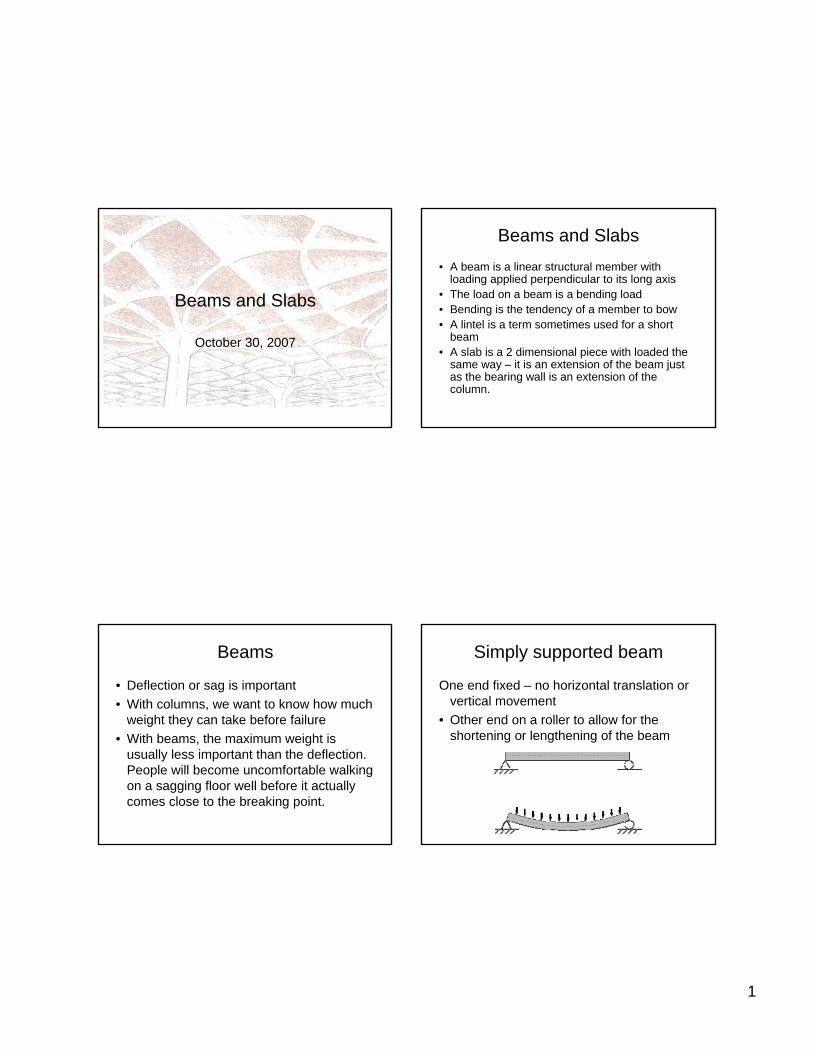
1 Beams and Slabs October 30, 2007 Beams and Slabs • A beam is a linear structural member with loading applied perpendicular to its long axis • The load on a beam is a bending load • Bending is the tendency of a member to bow • A lintel is a term sometimes used for a short beam • A slab is a 2 dimensional piece with loaded the same way – it is an extension of the beam just as the bearing wall is an extension of the column. Beams • Deflection or sag is important • With columns, we want to know how much weight they can take before failure • With beams, the maximum weight is usually less important than the deflection. People will become uncomfortable walking on a sagging floor well before it actually comes close to the breaking point. Simply supported beam One end fixed – no horizontal translation or vertical movement • Other end on a roller to allow for the shortening or lengthening of the beam
Transcript of Beams and Slabs - Siena Collegemmccolgan/Structures/Schedule_files/S...1 Beams and Slabs October 30,...
1
Beams and Slabs
October 30, 2007
Beams and Slabs• A beam is a linear structural member with
loading applied perpendicular to its long axis• The load on a beam is a bending load• Bending is the tendency of a member to bow• A lintel is a term sometimes used for a short
beam• A slab is a 2 dimensional piece with loaded the
same way – it is an extension of the beam just as the bearing wall is an extension of the column.
Beams
• Deflection or sag is important• With columns, we want to know how much
weight they can take before failure• With beams, the maximum weight is
usually less important than the deflection. People will become uncomfortable walking on a sagging floor well before it actually comes close to the breaking point.
Simply supported beam
One end fixed – no horizontal translation or vertical movement
• Other end on a roller to allow for the shortening or lengthening of the beam
2
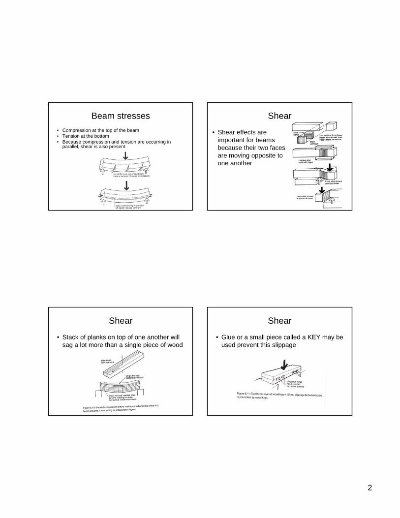
Beam stresses• Compression at the top of the beam• Tension at the bottom• Because compression and tension are occurring in
parallel, shear is also present
Shear
• Shear effects are important for beams because their two faces are moving opposite to one another
Shear
• Stack of planks on top of one another will sag a lot more than a single piece of wood
Shear
• Glue or a small piece called a KEY may be used prevent this slippage
3
Materials
• The best materials for beams are those which have similar strength in tension and compression
• Wood and steel are good materials• Concrete and masonry are poor choices
for long beams• Lintels are short beams and are often
made from concrete
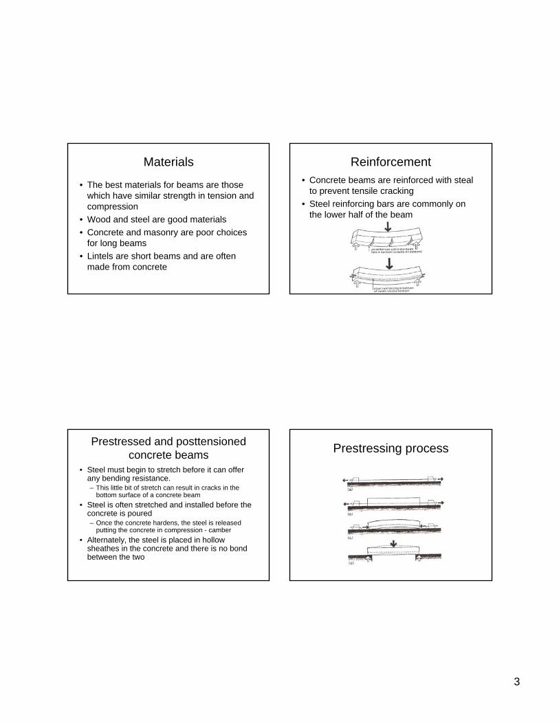
Reinforcement• Concrete beams are reinforced with steal
to prevent tensile cracking• Steel reinforcing bars are commonly on
the lower half of the beam
Prestressed and posttensionedconcrete beams
• Steel must begin to stretch before it can offer any bending resistance. – This little bit of stretch can result in cracks in the
bottom surface of a concrete beam• Steel is often stretched and installed before the
concrete is poured– Once the concrete hardens, the steel is released
putting the concrete in compression - camber• Alternately, the steel is placed in hollow
sheathes in the concrete and there is no bond between the two
Prestressing process
4
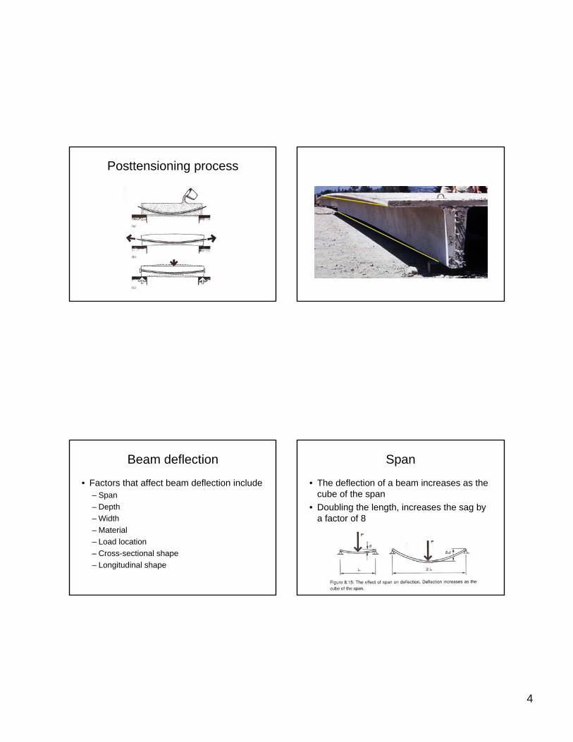
Posttensioning process
Beam deflection
• Factors that affect beam deflection include– Span– Depth– Width– Material– Load location– Cross-sectional shape– Longitudinal shape
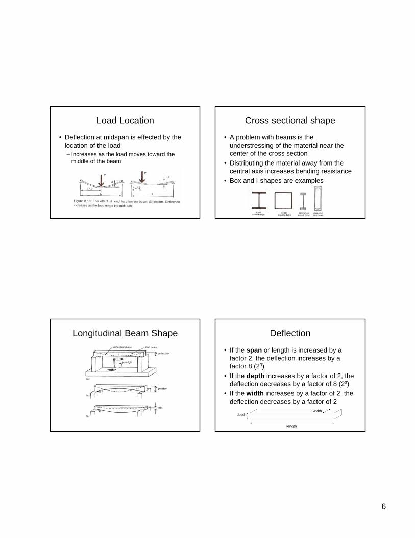
Span
• The deflection of a beam increases as the cube of the span
• Doubling the length, increases the sag by a factor of 8
5
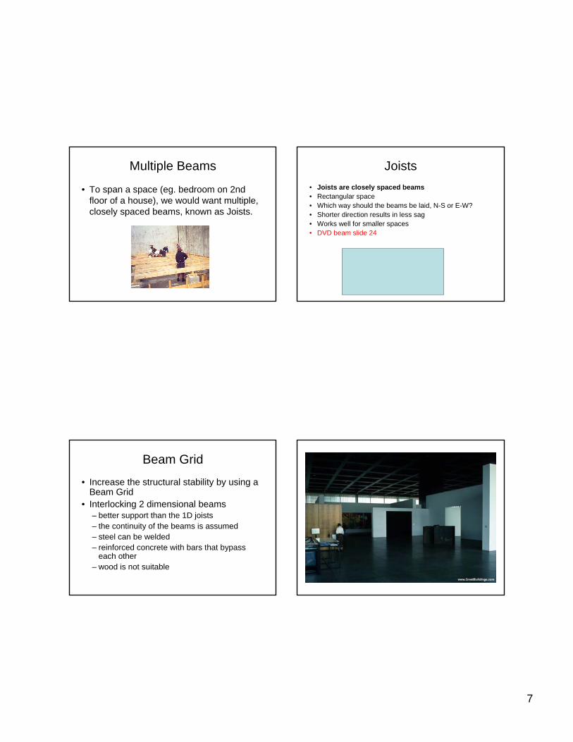
Width
• Deflection varies with its cross-sectional dimensions
• Deflection is inversely proportional to the horizontal dimension– Doubling the width reduced the deflection by one half
( )widthdeflection
Δ∝
1
0.5d
Depth• Deflection is inversely proportional to vertical
depth– Doubling the depth, reduces the deflection by a factor
of 8
• A beam has more stiffness by increasing the depth, as compared to the width
( )31
depthdeflection
Δ∝
8 d
Width and depth Material strength
• Deflection is inversely proportional to the modulus of elasticity of the material– Aluminum will deflect 3 times as much as
a comparable steel beam
( )elasticity of modulusΔ∝
1deflection
6
Load Location
• Deflection at midspan is effected by the location of the load– Increases as the load moves toward the
middle of the beam
Cross sectional shape
• A problem with beams is the understressing of the material near the center of the cross section
• Distributing the material away from the central axis increases bending resistance
• Box and I-shapes are examples
Longitudinal Beam Shape Deflection
• If the span or length is increased by a factor 2, the deflection increases by a factor 8 (23)
• If the depth increases by a factor of 2, the deflection decreases by a factor of 8 (23)
• If the width increases by a factor of 2, the deflection decreases by a factor of 2
length
depthwidth
7
Multiple Beams
• To span a space (eg. bedroom on 2nd floor of a house), we would want multiple, closely spaced beams, known as Joists.
Joists• Joists are closely spaced beams• Rectangular space• Which way should the beams be laid, N-S or E-W? • Shorter direction results in less sag • Works well for smaller spaces• DVD beam slide 24
Beam Grid
• Increase the structural stability by using a Beam Grid
• Interlocking 2 dimensional beams – better support than the 1D joists– the continuity of the beams is assumed – steel can be welded– reinforced concrete with bars that bypass
each other– wood is not suitable
8
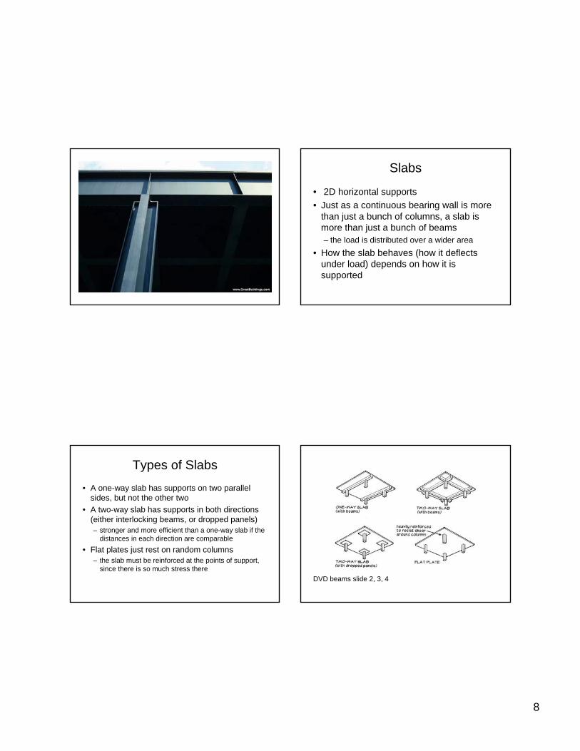
Slabs
• 2D horizontal supports • Just as a continuous bearing wall is more
than just a bunch of columns, a slab is more than just a bunch of beams– the load is distributed over a wider area
• How the slab behaves (how it deflects under load) depends on how it is supported
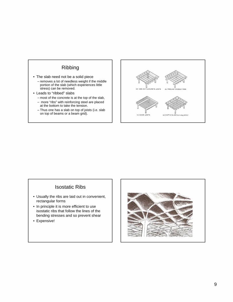
Types of Slabs
• A one-way slab has supports on two parallel sides, but not the other two
• A two-way slab has supports in both directions (either interlocking beams, or dropped panels)– stronger and more efficient than a one-way slab if the
distances in each direction are comparable• Flat plates just rest on random columns
– the slab must be reinforced at the points of support, since there is so much stress there
DVD beams slide 2, 3, 4
9
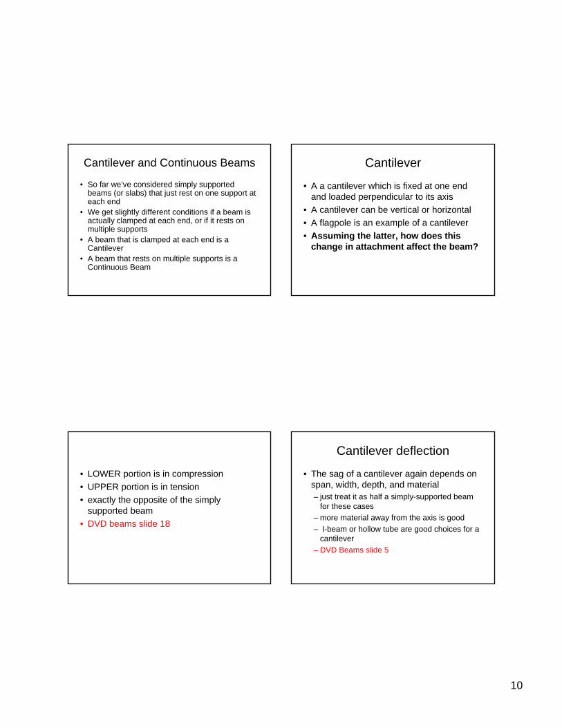
Ribbing
• The slab need not be a solid piece– removes a lot of needless weight if the middle
portion of the slab (which experiences little stress) can be removed.
• Leads to “ribbed” slabs– most of the concrete is at the top of the slab, – more “ribs” with reinforcing steel are placed
at the bottom to take the tension. – Thus one has a slab on top of joists (i.e. slab
on top of beams or a beam grid).
Isostatic Ribs
• Usually the ribs are laid out in convenient, rectangular forms
• In principle it is more efficient to use isostatic ribs that follow the lines of the bending stresses and so prevent shear
• Expensive!
10
Cantilever and Continuous Beams
• So far we’ve considered simply supported beams (or slabs) that just rest on one support at each end
• We get slightly different conditions if a beam is actually clamped at each end, or if it rests on multiple supports
• A beam that is clamped at each end is a Cantilever
• A beam that rests on multiple supports is a Continuous Beam
Cantilever
• A a cantilever which is fixed at one end and loaded perpendicular to its axis
• A cantilever can be vertical or horizontal• A flagpole is an example of a cantilever• Assuming the latter, how does this
change in attachment affect the beam?
• LOWER portion is in compression• UPPER portion is in tension• exactly the opposite of the simply
supported beam• DVD beams slide 18
Cantilever deflection
• The sag of a cantilever again depends on span, width, depth, and material – just treat it as half a simply-supported beam
for these cases– more material away from the axis is good– I-beam or hollow tube are good choices for a
cantilever – DVD Beams slide 5
11
Cantilever deflection – con’t
• The sag also depends on the shape of the cantilever
• Unlike a simply-supported beam, the cantilever has the greatest stress near the clamped end, so we want the most material at that end and little material at the free end
• A tapered shape is most efficient– need depth near support, but not out near load
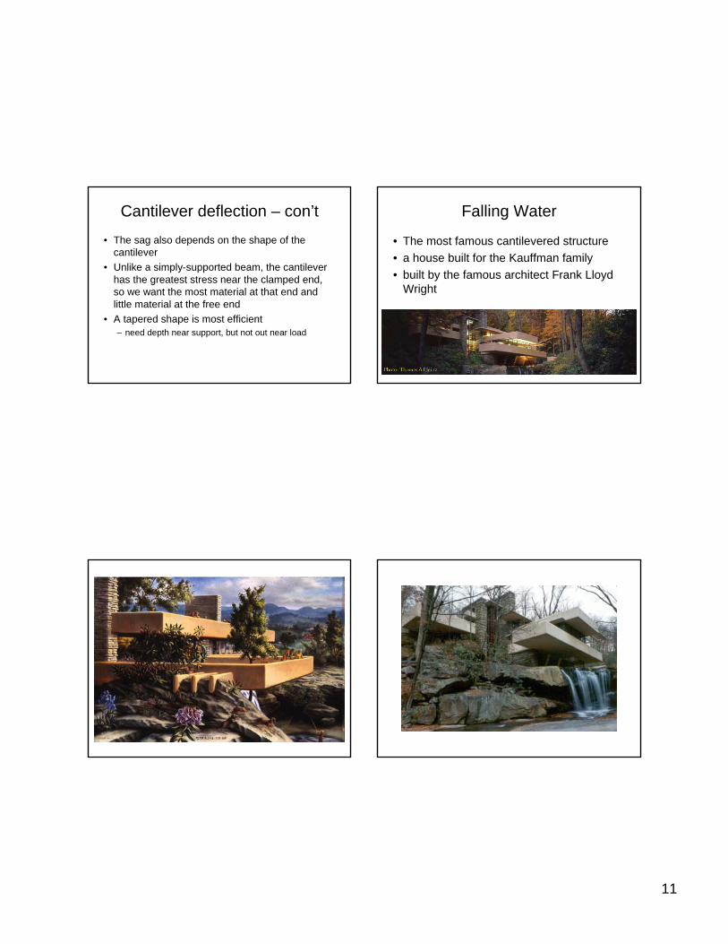
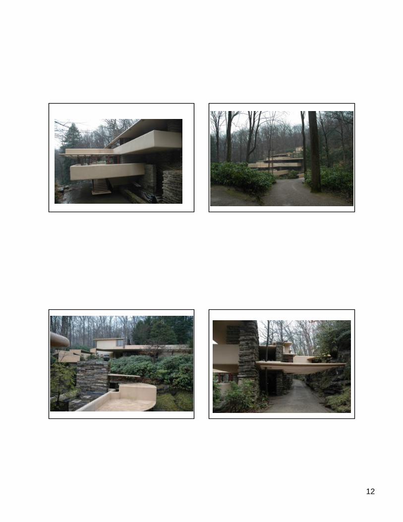
Falling Water
• The most famous cantilevered structure • a house built for the Kauffman family • built by the famous architect Frank Lloyd
Wright
12

13
Video!
• http://www.youtube.com/watch?v=gSRXHl9RbbU&mode=related&search=
Overhanging Beam
• In contrast to a cantilever is an overhanging beam
• As the name implies, the overhanging beam is a beam that extends out beyond its last support
• Unlike a cantilever the overhanging beam is allowed to rotate instead of being held rigidly
• DVD beam slide 5
• Which case would lead to more deflection?
14
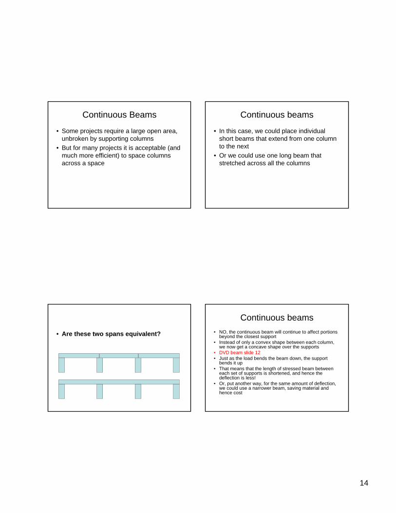
Continuous Beams
• Some projects require a large open area, unbroken by supporting columns
• But for many projects it is acceptable (and much more efficient) to space columns across a space
Continuous beams
• In this case, we could place individual short beams that extend from one column to the next
• Or we could use one long beam that stretched across all the columns
• Are these two spans equivalent?
Continuous beams• NO, the continuous beam will continue to affect portions
beyond the closest support• Instead of only a convex shape between each column,
we now get a concave shape over the supports • DVD beam slide 12• Just as the load bends the beam down, the support
bends it up• That means that the length of stressed beam between
each set of supports is shortened, and hence the deflection is less!
• Or, put another way, for the same amount of deflection, we could use a narrower beam, saving material and hence cost
15
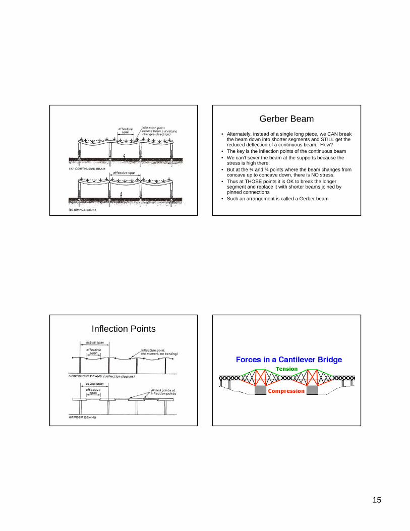
Gerber Beam• Alternately, instead of a single long piece, we CAN break
the beam down into shorter segments and STILL get the reduced deflection of a continuous beam. How?
• The key is the inflection points of the continuous beam • We can’t sever the beam at the supports because the
stress is high there. • But at the ¼ and ¾ points where the beam changes from
concave up to concave down, there is NO stress. • Thus at THOSE points it is OK to break the longer
segment and replace it with shorter beams joined by pinned connections
• Such an arrangement is called a Gerber beam
Inflection Points
16
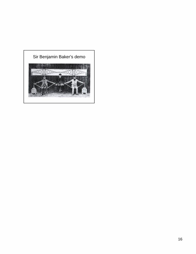
Sir Benjamin Baker’s demo