Beacon LKP NALA - Magnum Electronics, Inc. LKP NALA.book Page i Wednesday, February 25, 2009 5:34 PM...
40
-
Upload
nguyentruc -
Category
Documents
-
view
216 -
download
0
Transcript of Beacon LKP NALA - Magnum Electronics, Inc. LKP NALA.book Page i Wednesday, February 25, 2009 5:34 PM...

Beacon LKP NALA.book Page 1 Wednesday, February 25, 2009 5:34 PM

Beacon LKP NALA.book Page 2 Wednesday, February 25, 2009 5:34 PM
i English
CO
NTEN
TS
CONTENTSComputer Software Copyrights . . . . . . . . . . . . . iiSafety . . . . . . . . . . . . . . . . . . . . . . . . . . . . . . . . . . iiiRadio Overview . . . . . . . . . . . . . . . . . . . . . . . . . . 1LED Colors . . . . . . . . . . . . . . . . . . . . . . . . . . . . . . . 3LCD Display and Icons . . . . . . . . . . . . . . . . . . . . . . 4Programmable Buttons. . . . . . . . . . . . . . . . . . . . . . 5
Getting Started . . . . . . . . . . . . . . . . . . . . . . . . . . . 7Attaching and Removing the Antenna . . . . . . . . . . 7Attaching and Removing the Battery . . . . . . . . . . . 8Attaching and Removing the Belt Clip . . . . . . . . . . 9Charging the Battery. . . . . . . . . . . . . . . . . . . . . . . . 10
Scan . . . . . . . . . . . . . . . . . . . . . . . . . . . . . . . . . . . 12Deleting a Nuisance Scan Channel . . . . . . . . . . . . 12
Voice Operated Transmit (VOX) . . . . . . . . . . . . . 13Voice Inversion Scrambling . . . . . . . . . . . . . . . . 14
Front Panel Feature and Button Configuration Mode . . . . . . . . . . . . . . . . . . . . . . . . . . . . . . . . . . . 15Entering Front Panel Feature and Button Configuration Mode . . . . . . . . . . . . . . . . . . . . . . . . . . . . . . . . . . . . 15Exiting Front Panel Feature and Button Configuration Mode . . . . . . . . . . . . . . . . . . . . . . . . . . . . . . . . . . . . 15Assessing Front Panel Feature and Button Configuration Mode Parameters . . . . . . . . . . . . . . . . . . . . . . . . . . 15
TPL and DPL Frequencies and Codes . . . . . . . . 20TPL Frequency . . . . . . . . . . . . . . . . . . . . . . . . . . . . 20DPL Codes . . . . . . . . . . . . . . . . . . . . . . . . . . . . . . . 22
Warranty . . . . . . . . . . . . . . . . . . . . . . . . . . . . . . . . 25Accessories . . . . . . . . . . . . . . . . . . . . . . . . . . . . . 29
Beacon LKP NALA.book Page i Wednesday, February 25, 2009 5:34 PM

ii
CO
MPU
TER
SO
FTW
AR
E C
OPY
RIG
HTS
English
COMPUTER SOFTWARE COPYRIGHTSThe Motorola products described in this manual may include copyrighted Motorola computer programs stored in semiconductor memories or other media. Laws in the United States and other countries preserve for Motorola certain exclusive rights for copyrighted computer programs, including, but not limited to, the exclusive right to copy or reproduce in any form the copyrighted computer program. Accordingly, any copyrighted Motorola computer programs contained in the Motorola products described in this manual may not be copied, reproduced, modified, reverse-engineered, or distributed in any manner without the express written permission of Motorola.
Furthermore, the purchase of Motorola products shall not be deemed to grant either directly or by implication, estoppel, or otherwise, any license under the copyrights, patents or patent applications of Motorola, except for the normal non-exclusive license to use that arises by operation of law in the sale of a product.
Beacon LKP NALA.book Page ii Wednesday, February 25, 2009 5:34 PM

SAFETY
iii English
Beacon LKP NALA.book Page iii Wednesday, February 25, 2009 5:34 PM
SAFETY
PRODUCT SAFETY AND RF EXPOSURE COMPLIANCE
ATTENTION!
This radio is restricted to occupational use only to satisfy FCC RF energy exposure requirements. Before using this product, read the RF energy awareness information and operating instructions in the radio’s enclosed Quick Reference Card (Motorola Publication part number 68007024011) to ensure compliance with RF energy exposure limits.
Before using this product, read the operating instructions for safe usage contained in the Quick Reference Card enclosed with your radio.
!C a u t i o n

SAFE
TY
Eng
Beacon LKP NALA.book Page iv Wednesday, February 25, 2009 5:34 PM
ivlish
Notes

1 English
RA
DIO
OVER
VIEW
English
9 Accessory Connector 10 Programming Port
ront Programmable Buttons
eft/Right Button
Beacon LKP NALA.book Page 1 Wednesday, February 25, 2009 5:34 PM
RADIO OVERVIEW
CP185
6 Liquid Crystal Display (LCD)
5 Microphone
12 F
11 L
1 Channel Selector Knob2 On/Off and Volume Knob
3 LED Indicator
7 Push-to-Talk (PTT) Button
4 Speaker
8 Side Programmable Buttons

EnglishEn
RA
DIO
OVE
RVI
EW
PTT) Button to microphone to send message.
en to receive messages.el is programmed with the Busy Channel ature, the user can only transmit if the not in receiving mode.
mable Buttonsmmable Buttons" on page 5 for more
nnector port and 3.5 mm audio out port are used atible accessories to the radio.
Port lower port used by dealer to program the
ton menu, sub-menu or parameter nt Panel Feature and Button de.
mable Buttons mmable Buttons" on page 5 for more
Beacon LKP NALA.book Page 2 Wednesday, February 25, 2009 5:34 PM
2glish
1. Channel Selector KnobUsed to select channels in normal radio operation mode.
2. On/Off and Volume KnobTurn the ON/OFF/Volume Control knob clockwise to turn the radio ON.Turn the ON/OFF/Volume Control knob counterclockwise to turn the radio OFF.Turn this knob clockwise to increase the volume.Turn this knob counterclockwise to decrease the volume.
3. LED IndicatorIndicates radio transmit, receive, scan and monitor status. Refer to "LED Colors" on page 3 for more information.
4. SpeakerReceives audio messages through the speaker.
5. Microphone Speak into the microphone when sending messages.
6. Liquid Crystal Display (LCD)An 8 character single line display with up to 9 radio status icons. Refer to "LCD Display and Icons" on page 4 for more details.
7. Push-to-Talk (Press and speakRelease and listNote: If a chann
Lockout fechannel is
8. Side ProgramRefer to "Progradetails.
9. Accessory Co2.5 mm audio into connect comp
10. Programming2.5 mm audio inradio.
11. Left/Right ButUsed to navigateselections in FroConfiguration Mo
12. Front ProgramRefer to "Progradetails.

3 English
RA
DIO
OVER
VIEW
English
Beacon LKP NALA.book Page 3 Wednesday, February 25, 2009 5:34 PM
LED COLORSLED Color State IndicationGreen Illuminated Radio is transmitting in normal
mode.Radio is transmitting inScrambling Mode.
Normal Blinking Radio is receiving in normal mode.Channel is busy.Radio passed self-test during powering up.
Amber Illuminated Monitor activated.Permanent Sticky Monitor activated.
Normal Blinking Radio is in active Scan Mode. Radio is receiving in Scrambling Mode.
Red Normal Blinking Radio is transmitting in normal mode while battery is low. Radio is transmitting in Scrambling Mode while battery is low.
Fast Blinking Radio failed self-test during powering up.

EnglishEn
RA
DIO
OVE
RVI
EW
iption Function
ersionng
Illuminates when Scrambling Mode is on.
ming icator
Illuminates when Programming Mode is on.
ock Illuminates when keypad is locked.
evel
Shows remaining charge in battery based on how many bars (1 – 3) are displayed. Blinks when the battery is low.
Beacon LKP NALA.book Page 4 Wednesday, February 25, 2009 5:34 PM
4glish
LCD Display and IconsDisplays selected channel, programming parameters, status messages and any error or information messages.
LCD Indicator Description Function
Signal Strength Indicator
Shows the signal strength. More bars indicate a stronger signal received by radio.
Power Level Indicator
“L” illuminates to indicate radio is configured to transmit in low power; “H” illuminates when radio transmits in high power.
Talkaround Indicator
Illuminates when radio is not transmitting through the repeater.
Monitor Indicator
Illuminates when monitoring a selected channel.
Scan Indicator Blinks without dot when normal scan is activated.Illuminates without dot when there is some activity on a non-priority channel.Illuminates with dot blinking to indicate that there is some activity on the priority channel.
LCD Indicator Descr
Voice InvScrambliIndicator
ProgramMode Ind
Keypad LIndicator
Battery LIndicator

5 English
RA
DIO
OVER
VIEW
English
FunctionMonitors the channel for any activity as long as the button is pressed.
Removes unwanted channel(s) temporarily from scan list during Scan. Applicable for Long Press Only.
Enables or disables radio from requiring matching TPL/DPL to unsquelch.
Selects required power level: High or Low.
Select the Reverse Burst Type: None, 180 or 240.
Starts or stops Channel Scan.
Toggles between the two scrambling codes available.
Enables or disables scrambling feature for the selected channel. Applicable for Long Press Only.
Selects desired squelch level: Normal or Tight.
Toggles the permanent monitor function until the button is pressed again. Applicable for Long Press Only.
Enables toggle between repeater andtalkaround mode operations.
No function is programmed to this button.
Beacon LKP NALA.book Page 5 Wednesday, February 25, 2009 5:34 PM
Programmable ButtonsThe programmable buttons consist of:
• Side Programmable Button 1
• Side Programmable Button 2
• Front Programmable Button 1
• Front Programmable Button 2
• Front Programmable Button 3
The following functions can be assigned as short press i.e. press and release; or long press i.e. press and hold for more than 1 second.
Button FunctionBacklight Toggles backlight display between ON and OFF.
Channel Alias Toggles display between Channel Number and Channel Alias.
Keypad Lock Locks or unlocks all buttons except PTT, Side Programmable Button 1, Side Programmable Button 2, Channel Selector Knob and ON/OFF/Volume Knob. Applicable for Long Press Only.
ButtonMonitor
Nuisance Channel Delete
TPL/DPL Enable
Power Level
Reverse Burst
Channel Scan
Scrambling Code Select
Scrambling Enable/Disable
Squelch Level
Sticky Monitor
Talkaround/Repeater Mode
Unassigned

EnglishEn
RA
DIO
OVE
RVI
EW
assigned to your radio are described in
programmed your radio’s programmable nt to write down the new functions in the
Side Button 2
Front Button 1
Front Button 2
Front Button 3
nassigned Monitor Scan Power Level
nassigned Sticky Monitor
Nuisance Channel Delete
Unassigned
Side Button 2
Front Button 1
Front Button 2
Front Button 3
Beacon LKP NALA.book Page 6 Wednesday, February 25, 2009 5:34 PM
6glish
The default functionsthe table below.
If your dealer has re-buttons, you may watable below.
Button FunctionVolume Set Controls the audio level. A programmable button
used to control the audio level. The button emits a continuous tone to indicate the currentvolume level. To change volume level, turn thevolume knob to the desired level whilepressing the programmable button. Applicable for Long Press only.
VOX Enables or disables VOX feature for the selected channel.
Press Type
Side Button 1
Short Press
Unassigned U
Long Press
Unassigned U
Press Type
Side Button 1
Short Press
Long Press
7 English
GETTIN
G STA
RTED
a
ntenna to the radio by placing the of the antenna into the Antenna
tenna clockwise until tight.
nna in a counterclockwise direction until from the radio.
Beacon LKP NALA.book Page 7 Wednesday, February 25, 2009 5:34 PM
GETTING STARTED
Attaching and Removing the Antenna
To Attach Antenna
To Remove Antenn
CP185
Antenna Connector
Threaded Endof Antenna
1. Fasten the athreaded endConnector.
2. Rotate the an
1. Turn the anteit disengages

En
GET
TIN
G S
TAR
TED
y slots with the grooves on the radio.
tery upwards until a click is heard.
tery latch away from the radio.
tery downwards.
ry away from the radio.
Beacon LKP NALA.book Page 8 Wednesday, February 25, 2009 5:34 PM
8glish
Attaching and Removing the Battery To Attach Battery
To Remove Battery
Battery Slots
Grooves
BatteryLatch
1. Fit the batter
2. Slide the bat
1. Slide the bat
2. Slide the bat
3. Pull the batte

9 English
GETTIN
G STA
RTED
p
ng rails of the belt clip with the grooves
t clip downwards until it clicks into place.
a flat tool between the release tab and ace of the radio.
se tab.
t clip upwards.
Beacon LKP NALA.book Page 9 Wednesday, February 25, 2009 5:34 PM
Attaching and Removing the Belt Clip To Attach Belt Clip
To Remove Belt Cli
Release Tab
Mounting Grooves
1. Align mountiof the radio.
2. Slide the bel
1. Safely insertthe back surf
2. Lift the relea
3. Slide the bel

En
GET
TIN
G S
TAR
TED
r the battery insert visual guide line.
FF before charging the battery. Insert dio with a battery into the charger’s
groove on each side of the battery esponding raised rail on each side of pocket
battery towards the rear of the
attery into the charger pocket, mplete contact between the charger contacts.
D color will indicate the battery (See “Charging Status” on page 11).
Battery insert visual guide line
Battery Charging Tray
Beacon LKP NALA.book Page 10 Wednesday, February 25, 2009 5:34 PM
10glish
Charging the Battery
Refer to picture below fo
1. Make sure the radio is OFF.
2. Plug the power supply into an electric outlet.
3. Connect the power supply output cord connector into the rear of the Desktop Charging Tray.
4. The LED on the charger blinks green once to indicate charger is turned ON.
CP185
5. Turn the radio Oa battery, or a rapocket by:
aligning thewith the corrthe charger ORpressing thepocket ORsliding the bensuring coand battery
6. The charger’s LEcharging status.

11 English
GETTIN
G STA
RTED
Beacon LKP NALA.book Page 11 Wednesday, February 25, 2009 5:34 PM
Note: To get the maximum use from a new battery, charge it overnight (12 to 16 hours) before using the battery for the first time. The typical time needed to completely charge the discharged battery is estimated within 2.5 to 5 hours depending on its cell chemistry. Once the charger LED turns solid green, the charging process is done.
LED Color Charging Status
Solid Red Charging
Blinking Red Battery Fault
Solid Green Charge Complete
Blinking Green Trickle Charging
Single Green Blink Power On
Blinking Yellow Waiting to Charge

12English
SCA
N
SCAN
Scan allows you to monitor multiple channels and receive calls that are transmitted on them.
Two types of scan are supported: Normal Scan and Priority Scan. Normal Scan searches all channels sequentially in the radio’s scan list, whereas Priority Scan allocates 50% of the scanning time to the Priority Channel (the first channel in the designated scan list).
During scan, when activity is detected that meets the unsquelch condition, the radio stops scanning and switches to that channel; the G indicator is illuminated, and the channel number is displayed. When no activity is detected for a pre-set time, the radio resumes scanning.
If your radio has switched to a non-priority channel during priority scan, it still checks for activity on the priority channel. If activity is detected there, the radio switches to the priority channel.
The radio transmits on the Home Channel, if PTT is pressed during scanning. If the radio stops scanning, and changes to a particular channel, all transmit and receive activity is performed on that channel.• Press the Scan button to begin channel scanning. The G
indicator blinks to indicate that the radio is scanning. The LCD screen shows the Home Channel where the scan began.
• Press Scan button to stop scanning.
Deleting a Nuisance Scan ChannelA channel with unwanted activity is called a Nuisance Channel. You can remove a Nuisance Channel from the scan list temporarily. To remove a Nuisance Channel• Press the Nuisance Channel Delete programmable button,
when your radio stops on a Nuisance Channel. A high-pitched tone is heard.
You cannot remove the Home or Priority Channel from the scan list. If attempted, a low-pitched tone is heard, and no action is taken.To reinstate the deleted channel(s) into the scan list, restart scan, or simply turn off your radio and turn it on again.
Ch. 2 Ch. 3 Ch. 4
Ch. 1
Ch. 15
Ch. 14
Ch. 16 Home
Normal Scan
Start
Ch. 2 Ch. 1 Ch. 3
Ch. 1
Ch. 16
Ch. 1
Ch. 1 Home
Start
Priority ScanChannel 1 Prioritized
Beacon LKP NALA.book Page 12 Wednesday, February 25, 2009 5:34 PM

13 English
VOIC
E OPER
ATED
TR
AN
SMIT (VO
X)
VOICE OPERATED TRANSMIT (VOX)
VOX needs to be enabled for each channel in Customer Programming Software (CPS) before VOX Accessories can be used with radio. When the VOX headset/microphone is connected, your radio may be used in hands-free operation.
To start the VOX feature
1. Connect the VOX headset to the accessory connector of the radio. Make sure the radio is turned OFF before connecting the VOX accessory.
2. Turn the radio ON.
To disable the VOX feature
1. Press the PTT button on the radio. This allows you to use the VOX headset, but you must press the radio PTT to transmit.
To re-enable the VOX feature
1. Turn the radio OFF, and turn it ON again, with the headset connected to the accessory connector, or
2. Change channel with the VOX headset connected.
To adjust the VOX sensitivity level, see “ACCESORY (Accessory)” on page 17 of this user guide.
Beacon LKP NALA.book Page 13 Wednesday, February 25, 2009 5:34 PM

14English
VOIC
E IN
VER
SIO
N
SCR
AM
BLI
NG
VOICE INVERSION SCRAMBLING
Your radio has the Voice Inversion Scrambling feature which gives you an extra layer of privacy. This scrambling function is implemented via a frequency inversion in analog mode.
Note: This feature needs to be enabled using Customer Programming Software (CPS) before it can be activated.
To Enable and Disable the Scrambling Mode
Configure one of the programmable buttons for Scrambling Mode. Press this button to enable or disable the function. You can also configure this function via the Front Panel Feature and Button Configuration Mode (See "Entering Front Panel Feature and Button Configuration Mode" Menu on page 15).
To Change the Scrambling CodeConfigure one of the programmable buttons for Scrambling Code. Press this button to toggle between the two codes. You can also configure this function via the Front Panel Feature and Button Configuration Mode (See "Exiting Front Panel Feature and Button Configuration Mode" Menu on page 15).
Beacon LKP NALA.book Page 14 Wednesday, February 25, 2009 5:34 PM

15 English
FRO
NT PA
NEL FEA
TUR
E AN
D
BU
TTON
CO
NFIG
UR
ATIO
N M
OD
E
nt Panel Feature and Button Mode Parameters
to scroll through the parameters for enu item.
gs to select menu or sub-menu item.
n Without Changes or To ous Menu Levelable button 1 to return to previous menu
lection parameter without change.
Beacon LKP NALA.book Page 15 Wednesday, February 25, 2009 5:34 PM
FRONT PANEL FEATURE AND BUTTON CONFIGURATION MODE
This mode allows you to change the feature parameters to enhance the use of your radio.
Note: This mode must be enabled using Customer Programming Software (CPS) before it can be activated.
Entering Front Panel Feature and Button Configuration ModeIf your radio is turned ON, turn it OFF. Press and hold the side programmable button 1, and turn your radio ON. A tone is heard, indicating that your radio is in Feature and Button
Configuration Mode. The indicator illuminates and the “BCKLIGHT” is displayed on the radio LCD screen.
Exiting Front Panel Feature and Button Configuration ModeTurn the radio OFF to exit Feature and Button Configuration Mode.
Assessing FroConfiguration
To Navigate
Press the or each menu or sub-m
To Select SettinPress the PTT button
To Exit SelectioReturn To PreviPress side programmlevel or to exit the se
.

En
FRO
NT
PAN
EL F
EATU
RE
AN
D
BU
TTO
N C
ON
FIG
UR
ATI
ON
MO
DE
Remarks
O causes the backlight to automatically ere is no keypress for more than 5 seconds. acklight button again prolongs illumination
GLE allows the Backlight button ol the ON/OFF status of the backlight.
d the battery life. When enabled, it turns off circuitry periodically when no activity is
rns off the receiver less frequently. turns off the receiver for a longer duration to
ery saving.
e of battery that the radio uses.
Beacon LKP NALA.book Page 16 Wednesday, February 25, 2009 5:34 PM
16glish
Main Menu 1st Level Sub-Menu
2nd Level Sub-Menu Settings
BCKLIGHT(Backlight)
– – AUTO TOGGLE
Selecting AUTextinguish, if thPressing the Btime.Selecting TOGtoggle to contr
BATTERY SAVER(Battery Saver)
– OFFNORMALENHANCED
Helps to extenradio receiver detected. NORMAL – tuENHANCED –maximize batt
TYPE(Battery Type)
– NIMH (Nickel Metal Hydride)LI-ION (Lithium-Ion)H LI-ION (High Capacity Lithium- Ion)
Selects the typ

17 English
FRO
NT PA
NEL FEA
TUR
E AN
D
BU
TTON
CO
NFIG
UR
ATIO
N M
OD
E
Remarks
ou to adjust the external speaker loudness cessories are connected to radio. +2 will set the speaker gain to maximum level and -2 will set nal speaker gain to minimum level.
ou to adjust the externalne sensitivity when accessories are connected
et the external microphone sensitivity to
level and -2 will set the external microphone y to minimum level.
he alert tone volume preference.FF, if quiet operation is required.N, if working in a noisy environment.
Beacon LKP NALA.book Page 17 Wednesday, February 25, 2009 5:34 PM
Main Menu 1st Level Sub-Menu
2nd Level Sub-Menu Settings
ACCESORY(Accessory)
SPK GAIN(External Speaker Gain)
– +2+1 0-1-2
Allows ywhen acexternal the exter
MIC GAIN(External Microphone Gain)
– +2+1 0-1-2
Allows ymicrophoto radio.+2 will smaximumsensitivit
TONE VOL(Alert Tone Volume)
– – ONOFF
Selects tSelect OSelect O

En
FRO
NT
PAN
EL F
EATU
RE
AN
D
BU
TTO
N C
ON
FIG
UR
ATI
ON
MO
DE
Remarks
to select the range of Receive PL setting 67.0 - TPL 254.1, DPL 023 - DPL 754, user 1, user defined TPL 2, & user defined TPL cy is selected for PL display type.
to select the range of Receive PL setting 127, user defined TPL 1, user defined TPL fined TPL 3) if code is selected for PL .
to select the range of Transmit PL setting 67.0 - TPL 254.1, DPL 023 - DPL 754, user 1, user defined TPL 2, & user defined TPL cy is selected for PL display type.
to select the range of Transmit PL setting 127, user defined TPL 1, user defined TPL fined TPL 3) if code is selected for PL .
quelch level allows the radio to receive weak HT squelch level allows the radio to receive ls and eliminates unwanted noise.
ines the maximum duration (in seconds) that n transmit continuously.
Beacon LKP NALA.book Page 18 Wednesday, February 25, 2009 5:34 PM
18glish
Main Menu 1st Level Sub-Menu
2nd Level Sub-Menu Settings
CHANNEL RX PL (RX TPL/DPL)
CH-001...CH-016
CSQ CSQ067.0 … 001 ...254.1 042023 … or 043 754 127TPL 1 TPL 1TPL 2 TPL 2TPL 3 TPL 3
Allows you (CSQ, TPL defined TPL3) if frequenorAllows you (CSQ, 001 -2, & user dedisplay type
TX PL (TX TPL/DPL)
CH-001...CH-016
CSQ CSQ067.0 … 001 ...254.1 042023 … or 043 754 127TPL 1 TPL 1TPL 2 TPL 2TPL 3 TPL 3
Allows you (CSQ, TPL defined TPL3) if frequen orAllows you (CSQ, 001 -2, & user dedisplay type
SQUELCH(Squelch Level)
CH-001...CH-016
NORMALTIGHT
NORMAL ssignals. TIGstrong signa
TIME OUT (Time Out Timer)
– OFF010020...590600
This determthe radio ca

19 English
FRO
NT PA
NEL FEA
TUR
E AN
D
BU
TTON
CO
NFIG
UR
ATIO
N M
OD
E
Remarks
s you to set members of Scan List 1. “XXX” es the selected scan list member. “_ _ _” shows o scan list member is selected. can use the button or the to scroll the valid channel list and press PTT to
e selection.
s you to set the scan list for a selected channel.
s you to set scan type either Normal Scan or y Scan for a selected channel.
s you to set priority channel for scan list 1. denotes the selected priority channel. “_ _ _” that no priority channel is selected. User can se the button or the button to the valid channel list and press PTT to set the ion.
Beacon LKP NALA.book Page 19 Wednesday, February 25, 2009 5:34 PM
Main Menu 1st Level Sub-Menu
2nd Level Sub-Menu Settings
SCAN LIST 1(Scan List 1)
01-XXX02-XXX…15-XXX16-XXX
001…016
Allowdenotthat nUser buttonset th
LIST SEL(Scan List Select)
CH-001 … CH-016
LIST1 (Scan List 1) Allow
SCAN TYP(Scan Type Select)
CH-001 … CH-016
NORMALPRIORITY
AllowPriorit
PRIORITY(Priority Channel Select)
LIST1(Scan List 1)
_ _ _...XXX
Allow“XXX”showsalso uscroll select

En
TPL
AN
D D
PL
FREQ
UEN
CIE
S A
ND
ZB 012
1Z 013
1A 014
1B 015
2Z 016
2A 017
2B 018
3Z 019
3A 020
3B 021
4Z 022
4A 023
4B 024
5Z 025
5A 026
5B 027
6Z 028
6A 029
6B 030
le 1: TPL Frequency
Equivalent PL Code Motorola Code
Beacon LKP NALA.book Page 20 Wednesday, February 25, 2009 5:34 PM
20glish
TPL AND DPL FREQUENCIES AND CODES
The following information in the tables are to guide the user to select the appropriate TPL (Tone Private Line) or DPL (Digital Private Line) codes so that they can expand usage of the frequency.
TPL Frequency
Table 1: TPL Frequency
TPL Freq (Hz) Equivalent PL Code Motorola Code
67.0 XZ 001
69.3 WZ 002
71.9 XA 003
74.4 WA 004
77.0 XB 005
79.7 WB 006
82.5 YZ 007
85.4 YA 008
88.5 YB 009
91.5 ZZ 010
94.8 ZA 011
97.4
100.0
103.5
107.2
110.9
114.8
118.8
123.0
127.3
131.8
136.5
141.3
146.2
151.4
156.7
162.2
167.9
173.8
179.9
Tab
TPL Freq (Hz)

21
TPL AN
D D
PL FR
EQU
ENC
IES AN
D
English
Beacon LKP NALA.book Page 21 Wednesday, February 25, 2009 5:34 PM
186.2 7Z 031
192.8 7A 032
203.5 M1 033
206.5 8Z 034
210.7 M2 035
218.1 M3 036
225.7 M4 037
229.1 9Z 038
233.6* M5 039
241.8 M6 040
250.3 M7 041
254.1* 0Z 042
TPL1* – TPL1
TPL2* – TPL2
TPL 3* – TPL3
Note: The TPL Frequencies marked with an asterisk (*) are not part of the 39 standard EIA/TIA-603 CTCSS Code Frequency.
Table 1: TPL Frequency
TPL Freq (Hz) Equivalent PL Code Motorola Code

En
TPL
AN
D D
PL
FREQ
UEN
CIE
S A
ND
060
061
062
063
064
065
066
067
068
069
070
071
072
073
074
075
076
077
ble 2: DPL Codes
Motorola Code
Beacon LKP NALA.book Page 22 Wednesday, February 25, 2009 5:34 PM
22glish
DPL Codes
Table 2: DPL Codes
DPL Code Motorola Code
023 043
025 044
026 045
031 046
032 047
043 048
047 049
051 050
054 051
065 052
071 053
072 054
073 055
074 056
114 057
115 058
116 059
125
131
132
134
143
152
155
156
162
165
172
174
205
223
226
243
244
245
Ta
DPL Code

23
TPL AN
D D
PL FR
EQU
ENC
IES AN
D
English
096
097
098
099
100
101
102
103
104
105
106
107
108
109
110
111
112
113
ble 2: DPL Codes
Motorola Code
Beacon LKP NALA.book Page 23 Wednesday, February 25, 2009 5:34 PM
251 078
261 079
263 080
265 081
271 082
306 083
311 084
315 085
331 086
343 087
346 088
351 089
364 090
365 091
371 092
411 093
412 094
413 095
Table 2: DPL Codes
DPL Code Motorola Code
423
431
432
445
464
465
466
503
506
516
525(*)
532
546
565
606
612
624
627
Ta
DPL Code

En
TPL
AN
D D
PL
FREQ
UEN
CIE
S A
ND
Beacon LKP NALA.book Page 24 Wednesday, February 25, 2009 5:34 PM
24glish
631 114
632 115
645(*) 116
654 117
662 118
664 119
703 120
712 121
723 122
731 123
732 124
734 125
743 126
754 127
Note: The codes marked with an asterisk (*) are not part of the 83 standard EIA/TIA-603 codes.
Table 2: DPL Codes
DPL Code Motorola Code

25
WA
RR
AN
TY
English
WARRANTY Products and Accessories
s will be replaced during the riod if: falls below 80% of rated capacity, ors leakage.
Length of Coverage
Two (2) years
One (1) year
Six (6) months
The balance of the original warranty or for ninety (90) days from the date returned to the consumer, whichever is longer.
Beacon LKP NALA.book Page 25 Wednesday, February 25, 2009 5:34 PM
WHAT DOES THIS WARRANTY COVER?
MOTOROLA INC. ("MOTOROLA") warrants its MOTOROLA manufactured Radius Communication Products ("Product") against defects in material and workmanship under normal use and service for a period of time from the date of purchase as scheduled below:
NOTE:Rechargeable batterieapplicable warranty peA) the battery capacityB) the battery develop
Products Covered
CP185 Two-Way Radio
Motorola Accessories
Mag One Accessories
Products and Accessories that are Repaired or Replaced

Englis
WA
RR
AN
TY
MOTOROLA, at its option, will at no charge eitherrepair or replace this Product during the warranty
MOTOROLA cannot be responsible in any way for anyancillary equipment not furnished by MOTOROLA
or used in connection withtion of the Product with anyand all such equipment ism this warranty. Because eachuse the Product is unique, liability for range, coverage, ortem as a whole under this
ANTY DOES NOT COVERe resulting from use of then its normal and customary
from misuse, accident, water, or
age from improper testing,nce, installation, alteration,
ent.ge to antennas unless causedaterial workmanship.ted to unauthorized Productblies, or repairs (including,
addition to the Product of non-equipment) whichormance of the Product orOROLA's normal warranty
o verify any warranty claim.
Beacon LKP NALA.book Page 26 Wednesday, February 25, 2009 5:34 PM
26h
period provided it is returned in accordance with theterms of this warranty to the place of purchase. Repair,at MOTOROLA's option, may include the replacementof parts or boards with functionally equivalentreconditioned or new parts or boards. Replaced partsor boards are warranted for the balance of the originalapplicable warranty period. All replaced parts orProduct shall become the property of MOTOROLA.
This express limited warranty is extended byMOTOROLA to the original end user purchaser orlessee only and is not assignable or transferable toany other party. This is the complete warranty forProduct manufactured by MOTOROLA.
MOTOROLA assumes no obligations or liability foradditions or modifications to this warranty unless madein writing and signed by an officer of MOTOROLA.Unless made in a separate agreement betweenMOTOROLA and the original end user purchaser,MOTOROLA does not warrant the installation,maintenance or service of the product.
which is attached toProduct, or for operaancillary equipment expressly excluded frosystem which may MOTOROLA disclaimsoperation of the syswarranty.
WHAT THIS WARRA) Defects or damagProduct in other thamanner.B) Defects or damage neglect.C) Defects or damoperation, maintenamodification, or adjustmD) Breakage or damadirectly by defects in mE) A Product subjecmodifications, disassemwithout limitation, the MOTOROLA supplied adversely affect perfinterfere with MOTinspection andtesting of the Product t
27
WA
RR
AN
TY
English
F) Product which has had the serial number removedor made illegible.
Exclusions Physical Media. No warranty re will meet your requirements tion with any hardware or rovided by third parties, that the re products will be ree, or that all defects in the e corrected.ied in Physical Media. bodied in physical media (e.g. aded from the internet), is thout warranty.
only to the first consumer ansferable.
ARRANTY SERVICE OR ION?point of purchase.
IGHT NOTICE described in this manual may torola and third party software r memories or other media.
tes and other countries nd third party software
sive rights for copyrighted xclusive rights to distribute or ted software. Accordingly, any
Beacon LKP NALA.book Page 27 Wednesday, February 25, 2009 5:34 PM
G) Rechargeable batteries if:i) any of the seals on the battery enclosure of cells arebroken or show evidence of tampering.ii) the damage or defect is caused by charging or usingthe battery in equipment or service other than theProduct for which it is specified.H) Freight costs to the repair depot. Unapprovedupgrades or modifications.i) A Product which, due to illegal or unauthorizedalteration of the software/firmware in the Product, doesnot function in accordance with MOTOROLA'spublished specifications or the FCC type acceptancelabeling in effect for the Product at the time theProduct was initially distributed from MOTOROLA.
Software
Software Embodied inis made that the softwaor will work in combinasoftware applications poperation of the softwauninterrupted or error fsoftware products will bSoftware NOT EmbodSoftware that is not emsoftware that is downloprovided “as is” and wi
WHO IS COVERED?This warranty extends purchaser, and is not tr
HOW TO OBTAIN WOTHER INFORMATContact your Motorola
SOFTWARE COPYRThe Motorola productsinclude copyrighted Mostored in semiconductoLaws in the United Stapreserve for Motorola aproviders certain exclusoftware, such as the ereproduce the copyrigh
Products Covered Length of Coverage
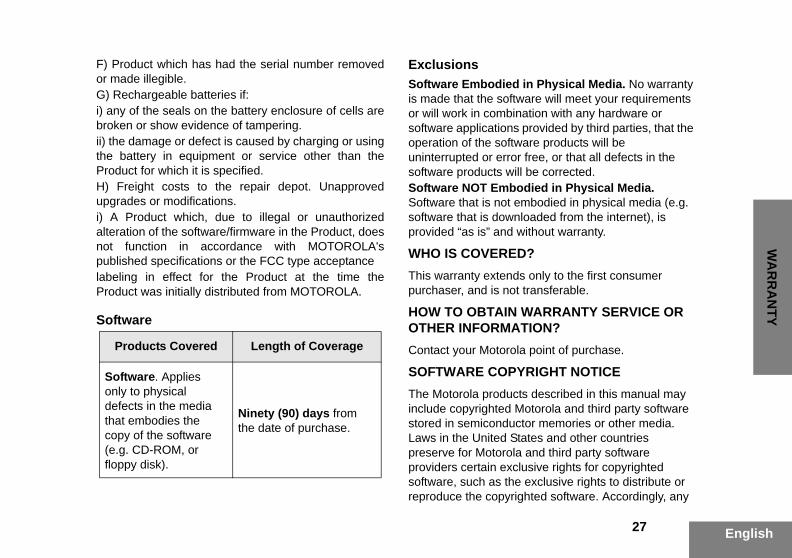
Software. Applies only to physical defects in the media that embodies the copy of the software (e.g. CD-ROM, or floppy disk).
Ninety (90) days from the date of purchase.

Englis
WA
RR
AN
TY
copyrighted software contained in the Motorola products may not be modified, reverse-engineered,
Beacon LKP NALA.book Page 28 Wednesday, February 25, 2009 5:34 PM
28h
distributed, or reproduced in any manner to the extent allowed by law.
Furthermore, the purchase of the Motorola products shall not be deemed to grant either directly or by implication, estoppel, or otherwise, any license under the copyrights, patents, or patent applications of Motorola or any third party software provider, except for the normal, non-exclusive, royalty-free license to use that arises by operation of law in the sale of a product.
PATENT NOTICEThis product is covered by one or more of the following United States patents.5896277 5894292 5864752 5699006 5742484 D408396 D399821 D387758 D389158 5894592 5893027 5789098 5734975 5861850 D395882 D383745 D389827 D389139 5929825 5926514 5953640 6071640 D413022 D416252 D416893 D433001
EXPORT LAW ASSURANCESThis product is controlled under the export regulationsof the United States of America. The Governments ofthe United States of America may restrict the exporta-tion or re-exportation of this product to certain destina-tions. For further information contact the U.S.Department of Commerce.

29
AC
CESSO
RIES
English
BATTERIES
Description
i-Ion High Capacity – 2150 mAh
i-Ion – 1500 mAh
iMH – 1300 mAh
Beacon LKP NALA.book Page 29 Wednesday, February 25, 2009 5:34 PM
ACCESSORIES
The following accessories parts are compatible with model number CP185.
ANTENNAS
Motorola Part Number Description
NAD6502_R VHF Heliflex Antenna, 146 – 174 Mhz
PMAD4049_ VHF Helical Antenna, 146 – 174 MHz
NAE6483_R UHF Whip Antenna, 403 – 520 MHz (16.5 cm)
PMAE4016_ UHF Whip Antenna, 403 – 520 MHz
Motorola Part Number
PMNN4080_R L
PMNN4081_R L
PMNN4082_R N

En
AC
CES
SOR
IES
UDIO ACCESSORIES
Description
AG ONE™ Branded
arbud with In-Line Microphone/PTT/VOX witch (MagOne)
ar Receiver with In-Line Microphone/PTT/OX Switch (MagOne)
arset with Boom Microphone and In-Line TT/VOX Switch (MagOne)
ltra-Light Headset with Boom Microphone nd In-Line PTT/VOX Switch (MagOne)
emote Speaker Microphone (MagOne)
OTOROLA Branded ightweight Single Muff Adjustable eadset with Swivel Boom Microphone
-wire Earpiece with Microphone and PTT ombined – Beige
eceive Only D-Style Earpiece (for MMN4013 Remote Speaker Microphone)
-Style Earpiece with Microphone/PTT
etail Temple Transducer Headset
Beacon LKP NALA.book Page 30 Wednesday, February 25, 2009 5:34 PM
30glish
CHARGERS AND POWER ADAPTERS
Motorola Part Number Description
PMLN5228_ Tri-Chem Single Unit Charger Base
PMLN5398_ Single Unit Charger Base with US 2-Pin Switch Mode Power Supply
EPNN9288_ 90 – 264 V, Switch Mode Power Supply with North America/Latin America country plug
A
Motorola Part Number
M
PMLN4442_ ES
PMLN4443_ EV
PMLN4444_ EP
PMLN4445_ Ua
PMMN4008_ R
MHMN9013_ L
H
HMN9754_ 2C
PMLN4620_ RP
PMLN5001_ D
PMLN5003_ R

31
AC
CESSO
RIES
English
ries may be or may not be available at the e. For latest information on accessories, torola point of purchase or visit: rola.com/governmentandenterprise.
DIO ACCESSORIES
Description
OTOROLA Branded eceive Only Flexible Earpiece (for MMN4013 Remote Speaker Microphone)
eceive Only Earbud (for PMMN4013emote Speaker Microphone)
MISCELLANEOUS
Description
pring Action Belt Clip (2 inch)
rotective Leather Case
Beacon LKP NALA.book Page 31 Wednesday, February 25, 2009 5:34 PM
Note: Certain accessotime of purchascontact your Mohttp://www.moto
AUDIO ACCESSORIES
Motorola Part Number Description
MOTOROLA Branded PMMN4013_ Remote Speaker Microphone with Ear Jack
PMMN4029_ Remote Speaker Microphone with IP57 Rating
RLN5317_ 2-wire Earpiece with Microphone and PTT Combined, Translucent Tube – Beige
RLN5318_ 2-wire Earpiece with Microphone and PTT Combined, Translucent Tube – Black
RLN4895_ 2-wire Earpiece with Microphone and PTT Combined – Black
RLN6230_ High Noise Kit, Black (Includes Foam Earplugs with Acoustic Tube)
RLN6231_ High Noise Kit, Beige (Includes Foam Earplugs with Acoustic Tube)
RLN6232_ Low Noise Kit, Black (Includes Rubber Tip with Acoustic Tube)
RLN6241_ Low Noise Kit, Beige (Includes Rubber Tip with Acoustic Tube)
RLN6242_ Quick Disconnect Acoustic Tube
RLN4941_ Receive Only Earpiece with Translucent Tube (for PMMN4013 Remote Speaker Microphone)
AU
Motorola Part Number
MWADN4190_ R
P
AARLN4885_ RR
Motorola Part Number
HLN9844_ S
PMLN5334_ P

En
AC
CES
SOR
IES
Beacon LKP NALA.book Page 32 Wednesday, February 25, 2009 5:34 PM
32glish
Notes

Beacon LKP NALA.book Page 33 Wednesday, February 25, 2009 5:34 PM

MOTOROLA and the Stylized M Logo are registered in the US Patent & Trademark Office.All other product or service names are the property of their respective owners.© 2008, 2009 by Motorola, Inc. All rights reserved.
*6878080A01*6878080A01-B
Beacon LKP NALA.book Page 34 Wednesday, February 25, 2009 5:34 PM