Basics of Metal Fatigue in Natural Gas Pipeline Systems — A Primer ...
58
Catalog No. L52270 Basics of Metal Fatigue in Natural Gas Pipeline Systems — A Primer for Gas Pipeline Operators Contract PR-302-03152 Prepared for the Materials Technical Committee of Pipeline Research Council International, Inc. Prepared by the following Research Agencies: Kiefner and Associates, Inc. Authors: M. J. Rosenfeld, PE J. F. Kiefner, PE, PhD Publication Date: June 2006
Transcript of Basics of Metal Fatigue in Natural Gas Pipeline Systems — A Primer ...
Catalog No. L52270
Basics of Metal Fatigue in Natural Gas
Pipeline Systems — A Primer for Gas Pipeline Operators
Contract PR-302-03152
Prepared for the Materials Technical Committee
of
Pipeline Research Council International, Inc.
Prepared by the following Research Agencies:
Kiefner and Associates, Inc.
Authors: M. J. Rosenfeld, PE
J. F. Kiefner, PE, PhD
Publication Date: June 2006

“This report is furnished to Pipeline Research Council International, Inc. (PRCI) under the terms of PRCI PR-302-03152, between PRCI and Kiefner and Associates, Inc. The contents of this report are published as received from Kiefner and Associates, Inc. The opinions, findings, and conclusions expressed in the report are those of the authors and not necessarily those of PRCI, its member companies, or their representatives. Publication and dissemination of this report by PRCI should not be considered an endorsement by PRCI or Kiefner and Associates, Inc, or the accuracy or validity of any opinions, findings, or conclusions expressed herein. In publishing this report, PRCI makes no warranty or representation, expressed or implied, with respect to the accuracy, completeness, usefulness, or fitness for purpose of the information contained herein, or that the use of any information, method, process, or apparatus disclosed in this report may not infringe on privately owned rights. PRCI assumes no liability with respect to the use of , or for damages resulting from the use of, any information, method, process, or apparatus disclosed in this report. The text of this publication, or any part thereof, may not be reproduced or transmitted in any form by any means, electronic or mechanical, including photocopying, recording, storage in an information retrieval system, or otherwise, without the prior, written approval of PRCI.”
Pipeline Research Council International Catalog No. L52270
Copyright, 2006 All Rights Reserved by Pipeline Research Council International, Inc.
PRCI Reports are Published by Technical Toolboxes, Inc.
3801 Kirby Drive, Suite 340 Houston, Texas 77098 Tel: 713-630-0505 Fax: 713-630-0560 Email: [email protected]

PIPELINE RESEARCH COUNCIL INTERNATIONAL, INC.
L. Stewart, Southern California Gas Company, Chairman
G. Aker, TransCanada PipeLines Limited A. Al-Ghamdi, Saudi Aramco
E. Amundsen, Panhandle Energy Company R. Barbeauld, Colonial Pipeline Company
J. Beringuier, Gaz de France R&D Division M. Bowin, Chevron Texaco Pipeline Company
C. Camerini, Petroleo Brasileiro S.A., PETROBRAS T. Collier, Columbia Gas Transmission Corporation
R. Englehart, Texas Gas Transmission, LLC W. Ferguson, CenterPoint Energy Gas Transmission Company
R. Graham, TransGas Limited E. Gustafson, Buckeye Partners, L.P. F. Haak, N.V. Nederlandse Gasunie W. Johnson II, El Paso Corporation
C. Linn, Williams Gas Pipeline D. Lytle, Gulf South Pipeline, LP
L. Mallett, TEPPCO A. Meyer, Enbridge Pipelines and Enbridge Energy Partners
J. Platt, BP J. Pustulka, National Fuel Gas Supply Corporation
P. Roberts, National Grid Transco P. Ruppert, Dominion Transmission
L, Schmitz, ConocoPhillips Pipe Line Company J. Schulze, Duke Energy Gas Transmission
W. Scott, Association of Oil Pipelines (AOPL) A. Smith, Shell Pipeline Company LP
D. Sprick, ExxonMobil Pipeline Company P. Stromme, Gassco A.S.
R. Turley, Marathon Ashland Pipe Line LLC J. Vainikka, Gasum Oy
R. Welsh, Consumers Energy J. Wenzell, Explorer Pipeline Company
E. Thomas, El Paso Corporation P. Altmayer, Gaz de France
J. Britain, National Grid Transco B. Cooper, Association of Oil Pipelines (AOPL)
L. Rodrigues Moreira PETROBRAS W. Shea, Jr., Buckeye Partners, L.P.
ii

This Page Intentionally Left Blank
DESIGN, CONSTRUCTION AND OPERATIONS TECHNICAL COMMITTEE
R. Gailing, Southern California Gas Company, Chairman
K. Hobeiche, ExxonMobil Pipeline Company, Vice Chairman
M. Al-Sannaa, Saudi Aramco P. Altmayer, Gaz de France
R. Barbeauld, Colonial Pipeline Company D. Batte, MACAW Engineering (Consultant Member)
S. Baumgardner, Marathon Ashland Pipe Line LLC R. Bergman, Chevron Texaco E&P Technology Company
K. Bodenhamer, Enterprise Products Partners, LP (AOPL Representative) M. Burton, Industrial Pipeline Solutions
S. Canterbury, Dominion Transmission, Inc. J. Derise, Shell Pipeline Company
G. Victor Peixoto Donato, PETROBRAS A. Drake, Duke Energy Company
R. Haycraft, Texas Gas Transmission LLC R. Healy, El Paso Corporation
R. Hoepner, Williams Gas Pipeline D. Johnson, CrossCountry Energy Services LLC M. Kornalijnslijper, N.V. Nederlandse Gasunie
D. Lawson, Enbridge Pipelines, Inc. J. Major, T.D. Williamson, Inc.
M. McLamb, BP p.l.c. D. Mitchell, Gulf South Pipeline Company, LP
P. Morrison, T.D. Williamson, Inc. S. Mundy, CenterPoint Energy Pipeline Services
S. Palazzo, Gulf South Pipeline C. Parker, TransGas Limited
J. Searfoss, Buckeye Pipe Line Company M. Smith, Pipeline Research Council International, Inc.
P. Stromme, Gassco A.S I. Taka-Aho, Gasum Oy J. Walker, GE Energy
B. Woodhouse, National Grid Transco J. Zhou, TransCanada PipeLines Limited
A. Al-Sharif, Saudi Aramco C. Amaral, Centro de Pesquisas da PETROBRAS, CENEPES
K. Blair, ExxonMobil R. Bood, National Grid Transco
K. Champagne, Shell Pipeline Company LP A. Geraldo de Sousa, PETROBRAS TRANSPORTE S.A.
T. Eilerman, Marathon Ashland Pipe Line LLC R. Espiner, BP Exploration
iii

K. Farnsworth, Chevron Pipe Line Company
R. Hoppe, PETROBRAS S. Koetting, ExxonMobil Pipeline Company
S. Kulkarni, Tennessee Gas Pipeline K. Kusmez, Saudi Aramco
A. Lambeth, Duke Energy Gas Transmission D. Moore, El Paso Corporation
M. Moseman, CrossCountry Energy Corp C. Ngo, TransCanada PipeLines Limited
D. Noronha, Jr., Centro de Pesquisas da PETROBRAS, CENEPES V. Azevedo Perrut Perrut, PETROBRAS
D. Ristig, CenterPoint Energy G. Robinson, Williams Gas Pipeline
S. Sanandres, PETROBRAS D. Stechschulte, Marathon Ashland Pipe Line LLC
M. Stephenson, BP America M. Zarea, Gaz de France R&D Division
ACKNOWLEDGEMENT
The authors wish to thank the following members of the PRCI technical committee for their thorough and thoughtful reviews:
Phillipe Altmeyer, Gaz de France Andy Drake, Duke Energy Rick Gailing, Southern California Gas Company Jerry Rau, Panhandle Energy Corporation
In addition, the authors wish to thank the following individuals for their expert review and comments:
Paul Lee, Southern California Gas Company Gary Vervake, Duke Energy Fred Wrenn, Wrentech Services, LLC John Zurcher, P-PIC, LLC
iv

TABLE OF CONTENTS
Page EXECUTIVE SUMMARY .......................................................................................................... vii INTRODUCTION .......................................................................................................................... 1 FATIGUE FUNDAMENTALS AND CONCEPTS....................................................................... 2 What is Fatigue? ............................................................................................................................. 2 Fatigue Initiation............................................................................................................................. 2 Fatigue Propagation ........................................................................................................................ 5 Final Fracture .................................................................................................................................. 7 PRESSURE CYCLE FATIGUE IN PIPELINE LONGITUDINAL SEAMS ............................... 8 Susceptible Longitudinal Seams ..................................................................................................... 8 Why Gas Pipelines Do Not Experience Fatigue in Longitudinal Seams...................................... 11 FATIGUE IN OTHER GAS PIPELINE-RELATED SITUATIONS .......................................... 13 Pulsation Bottles and Fabricated Assemblies ............................................................................... 14 Structural Vibrations..................................................................................................................... 15 Thermal Expansion Loads ............................................................................................................ 17 Structural Discontinuities.............................................................................................................. 18 Wrinkle Bends and Miters ............................................................................................................ 20 Dents and Mechanical Damage .................................................................................................... 21 Environmental Cracking ............................................................................................................... 24 IMPLICATIONS FOR INTEGRITY MANAGEMENT PLANNING........................................ 25 Keeping the Fatigue Threat in Perspective ................................................................................... 25 Integrity Management Planning Requirements ............................................................................ 26 REFERENCES ............................................................................................................................. 28
v

Table of Contents (Concluded) Page
Figures Figure 1. ASME Fatigue S-N Data and Design Curve ................................................................ 30 Figure 2. Typical Fatigue Failure Fracture Surfaces.................................................................... 31 Figure 3. Simplified Crack Model ............................................................................................... 31 Figure 4. Aggressive Gas Pipeline Operating Spectrum ............................................................. 31 Figure 5. Crack Propagation in Service ....................................................................................... 32 Figure 6. Some Typical Crack Growth Rate Data for Carbon Steel............................................ 32 Figure 7. Fatigue Crack Originating from ERW Seam Hook Crack ........................................... 33 Figure 8. Rail Shipment Fatigue Crack at Toe of DSAW Seam ................................................. 33 Figure 9. Aggressive Liquid Pipeline Operating Spectrum ......................................................... 34 Figure 10. Gas Pipeline Operating Spectrum .............................................................................. 34 Figure 11. Some Pulsation Bottles............................................................................................... 35 Figure 12. Pulsation Bottle Internals Undergoing Repair............................................................ 36 Figure 13. Bottle Shell Crack Due to Design Fault ..................................................................... 37 Figure 14. T-Joint Weld Details................................................................................................... 37 Figure 15. Structural Vibration Failure in Gas Pipeline Extruded Outlet.................................... 38 Figure 16. Flow Regimes Susceptible to Vortex Shedding ......................................................... 39 Figure 17. Fatigue Cracks at Poor Weld Profile on Branch Connection ..................................... 39 Figure 18. Example Fatigue Failures Adjacent to Heavy-Walled Attachments .......................... 40 Figure 19. Fatigue Crack Extending from SCC at Toe of Saddle Weld...................................... 41 Figure 20. Fatigue Crack Extending from SCC at Toe of DSAW Seam..................................... 41 Figure 21. Example Process for Addressing 192.917(e)(2)......................................................... 42
vi

7
EXECUTIVE SUMMARY
Occasionally and under certain circumstances, fatigue may constitute a potential threat to
the integrity of some pipelines. Part 192, Subpart O, “Implementing Integrity Management”,
Paragraph 192.917(e)(2) requires an operator to address the threat of “cyclic fatigue”. This
document explores the questions “What is fatigue?”, “Where can it occur in a gas pipeline
facility?”, and “What can be done about it?” The objective is to provide operators and others
interested in natural gas pipeline safety with a useful understanding of the extent to which fatigue
could pose a legitimate and actionable safety threat, as well as to demonstrate the authors’
opinion that in most respects, fatigue remains a comparatively minor risk component of the
overall spectrum of threats to natural gas pipeline safety.
Basic considerations of fatigue, physical testing of pipe, and operating experience have
shown that fatigue due to pressure cycles is not a limiting factor on the service life of sound pipe
free of gross defects. Fatigue in longitudinal seams due to the effects of pressure cycles acting
on longitudinal seam defects has only been observed where initial flaws were sufficiently large,
and even then only in certain liquid pipelines that operate in a cycle-intensive manner. Many
liquid pipelines are not subject to this threat, and no failures of this type have been identified in
gas pipelines. The reason for this is that gas pipelines do not experience a sufficient number of
large pressure cycles to cause fatigue crack growth to failure within the expected service life of
the facility, from initially present flaws that are small enough to survive a hydrostatic pressure
test to the usual margins above the MAOP.
In the infrequent occasions where fatigue does occur in gas pipeline facilities, it is
generally for reasons other than operational pressure cycles or where unusual circumstances were
present. Some scenarios involving fatigue affecting gas pipelines include: effects of pressure
pulsations or mechanical vibration associated with the operation of reciprocating compressor
units, inadequate bracing of above-ground piping subject to vibration, or vortex-shedding on pipe
exposed to water currents. Details of construction in fabricated assemblies, such as welding
quality and design choices, often affect susceptibility, as may damage to the surface of the pipe.
A hydrostatic pressure test or in-line inspection is unlikely to serve as an effective
assessment for the presence of these threats on the pipeline, or as a threat mitigation technique.
The reasons for this have to do with the nature of some susceptible facilities (e.g., piping or
appurtenances in compressor stations), the random nature of precipitating conditions or events
vii

8
(e.g., exposure of pipe to floodwaters), or the mode of fracture (e.g., circumferentially). Most
situations involving fatigue are best managed through a process involving observation of
conditions affecting a facility that could be conducive to fatigue, engineering evaluation on a
case-by-case basis, and corrective action as appropriate. A sample process for identifying
systems potentially susceptible to “cyclic fatigue” and other threats identified in paragraph
192.917(e)(2) is included.
viii

1
BASICS OF METAL FATIGUE IN NATURAL GAS PIPELINE SYSTEMS — A PRIMER FOR GAS PIPELINE OPERATORS
M. J. Rosenfeld, PE and J. F. Kiefner, PE, PhD Kiefner & Associates, Inc.
INTRODUCTION
The natural gas pipeline industry is rapidly implementing comprehensive integrity
management practices to meet the demands of new regulatory imperatives and public interests.
These new demands require formal integrity management planning programs be developed and
applied where pipeline failures could affect “High Consequence Areas”. A formal integrity
management plan (IMP) incorporates some process for identifying threats to a pipeline’s
integrity. Such threats come in many forms and are uniquely dependent on a wide range of
attributes associated with an individual pipeline segment. Once such threats are identified, the
pipeline operator must characterize the degree of risk associated with the threat as a means of
prioritizing responses, identify suitable methods to assess the presence of the threat, and develop
appropriate mitigations.
Interest (or concern) has arisen regarding metal fatigue as one such possible integrity
threat. We know from some pipeline failures that occasionally and under certain circumstances,
fatigue may constitute a potential threat. More to the point, 49 CFR Part 192, Subpart O,
“Implementing Integrity Management”, Paragraph 192.917(e)(2) requires an operator to address
the threat of “cyclic fatigue”. In order to meet the objectives and requirements of this rule, a
pipeline operator must be able to discern what types of pipe or piping construction are
susceptible to fatigue, what modes of pipeline operation or situations are conducive to fatigue,
the consequences of a fatigue-related incident, and what actions could be taken to mitigate the
threat. At the request of the Pipeline Research Council International (PRCI), the Gas
Technology Institute (GTI), and the Interstate Natural Gas Association of America (INGAA) this
review was undertaken to provide fundamental information to gas pipeline operators to enable
them to address issues of fatigue as they pertain to natural gas pipelines. In so doing, the
document will explore the questions “What is fatigue?”, “Where can it occur in a gas pipeline
facility?”, and “What can be done about it?”
2
The cumulative body of knowledge derived by theory, test, and experience on the subject
of fatigue and its effects on piping, pressurized equipment, and welded structures is vast in scope
and detail, and it is not the intention of this document to summarize that. Rather, it is intended
that this document provide natural gas pipeline operators and others interested in natural gas
pipeline safety with a useful understanding of the extent to which fatigue could pose a legitimate
and actionable safety threat, as well as to demonstrate the authors’ opinion that in most respects,
fatigue remains a comparatively minor risk component of the overall spectrum of threats to
natural gas pipeline safety.
FATIGUE FUNDAMENTALS AND CONCEPTS
What is Fatigue?
Fatigue is a process of structural degradation caused by fluctuations or cycles of stress or
strain. Such stresses or strains are typically concentrated locally by structural discontinuities,
geometric notches, surface irregularities or damage, defects, or metallurgical nonhomogeneities.
Fatigue may occur in three sequential stages: the formation of a crack, called “initiation”; the
stable incremental enlargement of the crack in service, called “propagation”; and rapid unstable
fracture, i.e., failure. Fatigue arises as a result of accumulated cycles of applied stress in service.
The term “cycles” implies a repetitive loading condition or a randomly fluctuating load. Fatigue
is not caused by a steady load or a one-time loading event. The phases of initiation, propagation,
and final failure, though sequential, are distinct and governed by separate considerations.
Fatigue Initiation
Initiation of fatigue occurs at microstructure-scale nucleation sites within the material
such as inclusions, pores, or soft grained regions, or as they become generated through
microvoid coalescence by the straining process.[1] The presence of macro-scale stress
concentrators, or more accurately strain concentrating features, enhances this process. Examples
of stress concentrators are:
• grooves or notches
• threads
• abrupt transitions in metal thickness
• weld bead toes
3
• welding workmanship flaws
• manufacturing flaws in the pipe seam or pipe body
• pipe deformations such as dents or buckles
• mechanical damage such as gouges
• sites of environmental attack such as corrosion pits or stress-corrosion cracks.
Stress concentrators generically are characterized by a notch or notch-like geometry. A
sharp notch will be more prone to form a fatigue crack than a blunt notch when subjected to the
same cyclical loading conditions, because the sharper notch produces a more severe
concentration of strain locally at its root. While it is true that fatigue can occur eventually if
stress cycles are sufficiently numerous and large in magnitude, even where the material surface
is free of gross stress-concentrating features, so many cycles of stress would be required for
fatigue to initiate in the absence of a stress-concentrating feature that this is not a scenario of
concern in a gas pipeline context, as will be demonstrated subsequently in this report.
Conversely, the onset of fatigue is promoted by the presence of stress-concentrating features in
proportion to their severity. This has important implications for pipe affected by mechanical
damage.
The fatigue-crack-initiation behavior of a material is described by an “S-N” curve, which
is a graph of the magnitude of cyclical stress amplitude, S (amplitude being half the total range
of stress cycle or variation), plotted against the number of cycles, N, in which the cyclic stress
amplitude will cause a failure. Some S-N data for plain carbon steel and low-alloy steel are
shown in Figure 1(a).[2] The S-N curves are empirically derived from large numbers of tests in
which polished round bars of material are cyclically loaded at specific nominal stress levels until
fracture occurs. The data in Figure 1(a) were used as the basis for the fatigue design S-N curve
in the ASME Boiler and Pressure Vessel Code (BPVC), Section VIII, Division 2, Appendix 5
shown in Figure 1(b). The curve is drawn well below the data points to provide a factor of
safety. S-N curves for specific materials or structural weldment configurations can be found in
other design standards and fitness-for-purpose standards as well.
The S-N curve demonstrates that larger cycles of stress result in failure in fewer cycle
occurrences, while smaller cycles of stress result in failure after a greater number of cycles. At
the left end of the curve, the stress amplitudes may greatly exceed the yield strength of the
material, because what is shown as “stress” is actually a computed pseudo-elastic stress quantity

4
based on local strain that could fall well into the plastic range locally. The stress includes the
concentrating effect of any notch. Large amounts of plasticity hasten the fatigue initiation
process, resulting in failure in fewer cycles. This region of fatigue performance is sometimes
referred to as “low-cycle fatigue” because it pertains to failure in a relatively low number of load
cycles. At the right end of the curve, on the order of 105 or more cycles of stress are tolerable, if
the magnitude of stress cycles is very low. This region of fatigue performance is sometimes
referred to as “high-cycle fatigue” because it pertains to failure in a large number of load cycles.
If stress amplitude is sufficiently low, the S-N curve flattens out and the fatigue life is infinite for
practical purposes. This stress level is referred to as the “endurance limit”. As-finished pipe and
welds may not exhibit an endurance limit.[15]
The S-N curves are developed from tests to failure, so the number of cycles includes the
propagation and final fracture phases of fatigue without explicitly describing them. It is
presumed that in the absence of an initial crack, these phases comprise a very small proportion of
the overall fatigue life.
The fatigue-initiation characteristics of a given material, design feature geometry, surface
finish characteristics, and loading level are of great importance to the design of rotating
machinery, vehicles, aircraft, and highway bridges because such structures rapidly accumulate
millions of individual stress cycles. In contrast, the initiation phase of fatigue is of little concern
with the pressure design of pipe, because the magnitude of hoop stress cycles due to pressure
variation is in the range where 105 to 106 pressure cycles from 0-MAOP-0 would be required to
cause failure, and this is far more than most pipelines would be expected to experience. The
initiation phase of fatigue is a significant consideration in the design of piping systems that are
free to flex in response to changes in operating temperature, such as piping systems located in
refineries, power plants, or other process facilities. Here, the problem is not that stress cycles
due to changes in operating temperature are particularly numerous, but rather that they are large
in magnitude. The magnitude of flexural stress cycles in piping components, such as elbows and
tees, are magnified by their geometries such that the range of stress cycle may be much greater
than the yield strength of the material. Appropriate design for such circumstances is achieved by
performing a piping “flexibility analysis” in accordance with the design rules for above-ground
piping systems contained in standards such as the ASME B31 Code for Pressure Piping.
5
The resistance to fatigue crack initiation is generally proportional to ultimate tensile
strength properties. However, the range of ultimate tensile strengths in line pipe does not vary
over a sufficiently large range for this to be a significant factor. Resistance to fatigue initiation is
enhanced by improvements in surface finish quality (smoother being better) and by treatments
that impart compressive residual surface stresses (e.g., peening) or hardened surface
microstructures (e.g., induction case hardening). Such treatments may be important to rotating
machinery because they are initiation-sensitive owing to their high-cycle loading environment,
but are not generally of value with pipe.
It is often assumed by equipment designers that the effects of fatigue are cumulative, in
accordance with Miner’s Rule of Linear Cumulative Damage. This rule of thumb states that the
sum of fatigue-life fractions of various stress ranges, perhaps associated with different loadings
or modes of operation, can be summed. Failure would be expected when the life fraction sum
equals a value of 1. (Note that Miner’s Rule cannot be assumed to apply when performing the
explicit fatigue propagation analysis discussed in the following section, because incremental
crack growth is not necessarily linear.)
Fatigue Propagation
The initiation process described above causes the formation of a crack in otherwise
sound, uncracked metal. As load cycles accumulate, initiation is followed by propagation or
enlargement of the crack in service. Fatigue failures frequently exhibit prominent concentric
features on the exposed fracture surfaces, such as what is shown in Figure 2. These marks,
referred to as “beach marks”, indicate the incremental enlargement of the crack with continued
cycles of loading in service. These fracture features are often somewhat elliptical in profile and
typically are seen to emanate from the initial flaw, notch, area of local damage, or other stress
concentration.
Propagation necessarily concerns a crack that is already present, so it is most useful to
consider propagation in terms of parameters related to fracture mechanics. The crack-tip stress-
intensity is an expression of the theoretical stress at the tip of a crack, derived from linear elastic
fracture mechanics as K = f [geometry] × σ × (πa)1/2, where σ is a nominal applied stress, a is the
crack size, and K is expressed in U.S. Customary units of ksi-(in)1/2 or in metric units of
6
MPa(mm)1/2. The geometry factor accounts for the crack’s configuration and its orientation in
the plate. The geometry factor may change as the flaw enlarges.
The idealized configuration of a surface-breaking crack having a semi-elliptical shape,
Figure 3, is the principal one of interest in dealing with seam susceptibility issues in line pipe,
since the concern is for features having configurations similar to this. Various expressions for
the crack-tip stress intensity at the tip of a semi-elliptical surface flaw in a plate have been
developed, with some variations or alternatives. [3,4]
The stresses in service fluctuate over a range, ∆σ, so the fluctuation in stress-intensity is
∆K = f [geometry] × ∆σ × (πa)1/2. An operating pressure spectrum for a natural gas pipeline may
look something like what is shown in Figure 4. Typically the largest cyclical component is
seasonal, which means it occurs once per year. (Some pressure signals appear to go toward zero,
implying a large pressure cycle. Most likely these are the result of instruments being taken off
line for calibration or other events, rather than actual pressure swings.) The pressure signal is
“stochastic”, meaning it consists of an apparently random mix of signal amplitudes. In order to
usefully account for the variations in stress, the operating history must be decomposed in terms
of the number of cycles of various magnitudes. This is normally accomplished by performing a
“rainflow” cycle-counting algorithm.[5] (The term“rainflow” is used because the analysis
captures the effects of larger cycles widely separated in time, somewhat analogously to how a
multilevel roof sheds rain to a wider lower-level roofline.)
Propagation or growth of a fatigue crack in service is governed by the “Paris Law”, given
as da/dN = C [∆K]n where da/dN is the increment of crack extension per load cycle, ∆K is the
magnitude of the range of alternating crack-tip stress intensity associated with a given load cycle
acting on the crack of size a, and C and n are material properties. The size of the crack, a, thus
increases incrementally by ∆a with each load cycle ∆N while the magnitude of the stress-
intensity range, ∆K, increases with each increment of crack growth. The form of the Paris Law
results in an exponential increase in crack growth rate and an acceleration of crack size as load
cycles accumulate, as illustrated by Figure 5.[3] The practical implication of this is that a small
crack may remain small for a long time, and by the time it is detectable, either by means of in-
service examination (e.g., crack detection ILI) or proof load testing (e.g., hydrostatic pressure
test), the remaining safe service life could be very short. The effect of a larger initial flaw is to
7
move the curve to the left, resulting in failure in fewer cycles. This suggests that achieving the
largest possible margin between the test pressure and the operating pressure is of value to
maximizing the retest interval where pressure testing is used as the method of assessment.
The value of C can vary by several orders of magnitude, while n has been observed to
vary from 2 to 4, though for most pipeline materials n usually seems to fall between 2.5 and 3.
A higher C and lower n will result in a faster initial crack growth rate that does not accelerate as
greatly toward failure compared to a lower C and higher n, which results in very flat initial crack
growth rate and more rapid acceleration toward final failure. If only an initial and a final flaw
size are known, there is no one combination of C and n that uniquely defines the crack growth
curve between initial and final flaw sizes for any given operating spectrum. “Typical” values
reported for C and n in plain carbon steel are C = 3.6x10⁻¹⁰ and n = 3.0 for ∆K expressed in units
of ksi(in)1/2, though any given steel might exhibit very different values for the crack growth rate
parameters. This “typical” relationship between da/dN and ∆K is shown in Figure 6.[6] Some
fitness-for-purpose standards (e.g., API 579) also recommend higher C values specifically for
welds in order to account for residual stresses.
The values of C and n are influenced somewhat by load cycle frequency and stress ratio
(R, the ratio of minimum to maximum stress in a cycle), and may be influenced strongly by the
chemistry environment that the crack tip becomes exposed to (e.g., dry versus aqueous, or the
presence of oxygen, chlorides, sulfur, or hydrogen).[6] The exposure of the fracture to
environments at the soil interface, under coatings, or in the pipe interior could enhance crack
growth rates compared to those indicated by the “typical” coefficients.
“Retardation” (of the crack growth) occurs where an infrequent overload cycle blunts the
crack tip and introduces a large plastic zone ahead of the crack. When the proof load is released,
the residual stress field in the plastic zone is compressive, causing a delay in subsequent crack
growth. Theoretically, beneficial retardation effects might be expected to occur in conjunction
with high hydrostatic proof test pressures. While retardation is a proven phenomenon, it may not
occur to a significant degree where the proof test is not greatly above the normal operating
stress. (It does appear to play a role in delaying continued extension of near-neutral-pH SCC if
the pressure test exceeds 100% of SMYS.) The effect of retardation is usually disregarded when

8
performing incremental fatigue crack growth computations for pipelines because assuming that it
may have been operative when it actually may not have would be unconservative.
Accurate crack-growth life prediction methods do not exist in closed form. It should be
apparent from the foregoing discussion that performing fatigue crack-growth life predictions is a
highly technical process that requires specialized knowledge and some computational
capabilities. It is not the sort of analysis that many pipeline operators are in a position to readily
perform on a routine basis.
Final Fracture
The final stage of fatigue crack growth occurs when the crack-growth rate accelerates
under the influence of ductile tearing and the crack grows to such size that it could fail at the
next applied load cycle. The critical flaw size depends on the nominal stress, the material
strength, and the fracture toughness. The crack configuration most relevant to the concern for
pressure-cycle-induced fatigue is a longitudinal defect in pressurized pipe, for which accepted
models exist.[7]
PRESSURE CYCLE FATIGUE IN PIPELINE LONGITUDINAL SEAMS
Susceptible Longitudinal Seams
Although it will be demonstrated subsequently that fatigue in longitudinal seams would
not be expected to be an issue in any gas pipeline, it is worth reviewing which types of
longitudinal seams have demonstrated susceptibility to fatigue, at least in a few liquid pipelines,
as this appears to be a basis for the so-called “material threat” contained in Paragraph
192.917(e). The reader should keep in mind that fatigue crack growth in longitudinal seams as a
result of pressure cycles has been experienced only in a subset of liquid products pipelines in
which the pipe was affected by certain species of seam defect conditions, and the lines operated
with relatively intensive pressure cycles. It would be quite incorrect to project this susceptibility
to all liquid pipelines, or to all pipelines having a particular form of longitudinal seam.
ERW Type Seams
Autogoneous weld seams (e.g., electric resistance-welded and electric flash-welded
9
seams) are potentially susceptible to the occurrence of various types of defects, but not all have
been associated with fatigue from pressure cycles. In every case involving fatigue in
autogenous seams, the initial flaws are artifacts of the manufacturing process that escaped
detection by the inspection process in the pipe mill and that were also small enough to pass the
hydrostatic test at the mill or in the field prior to commissioning. Cold weld or lack-of-fusion
defects that lie on the bondline of low-frequency-welded or dc-welded ERW seams have not
been seen to grow by fatigue because the extremely low toughness of the bondline means that
defects large enough to be affected by service stresses simply cannot survive and will therefore
not be present.[8] Theoretically, bondline lack-of-fusion defects could grow by fatigue where
the seam was made by the high-frequency ERW process, because the seam is sufficiently tough
to permit large enough starter cracks to exist. However, the high-frequency welded ERW seams
have typically not exhibited the large bondline lack-of-fusion defects that affected some earlier
types of ERW pipe, due mainly to the more reliable bonding of the skelp edges afforded by the
high-frequency current and perhaps also to improved inspection methods in the pipe mill.
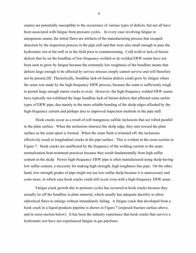
Hook cracks occur as a result of soft manganese sulfide inclusions that are rolled parallel
to the plate surface. When the inclusions intersect the skelp edge, they turn toward the plate
surface as the seam upset is formed. When the seam flash is trimmed off, the inclusions
effectively result in longitudinal cracks at the pipe surface. This is evident in the cross-section in
Figure 7. Hook cracks are unaffected by the frequency of the welding current or the seam
normalization heat-treatment practices because they result fundamentally from high sulfur
content in the skelp. Newer high-frequency ERW pipe is often manufactured using skelp having
low sulfur content, a necessity for making high-strength, high-toughness line pipe. On the other
hand, low-strength grades of pipe might not use low-sulfur skelp because it is unnecessary and
costs more, in which case hook cracks could still occur even with a high-frequency ERW seam.
Fatigue crack growth due to pressure cycles has occurred at hook cracks because they
actually lie off the bondline in plate material, which usually has adequate ductility to allow
subcritical flaws to enlarge without immediately failing. A fatigue crack that developed from a
hook crack in a liquid products pipeline is shown in Figure 7 (exposed fracture surface above,
and in cross-section below). It has been the industry experience that hook cracks that survive a
hydrostatic test have not experienced fatigue in gas pipelines.
10
Transportation Fatigue Defects
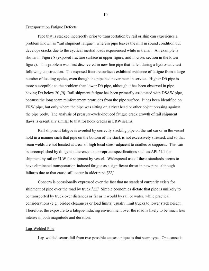
Pipe that is stacked incorrectly prior to transportation by rail or ship can experience a
problem known as “rail shipment fatigue”, wherein pipe leaves the mill in sound condition but
develops cracks due to the cyclical inertial loads experienced while in transit. An example is
shown in Figure 8 (exposed fracture surface in upper figure, and in cross-section in the lower
figure). This problem was first discovered in new line pipe that failed during a hydrostatic test
following construction. The exposed fracture surfaces exhibited evidence of fatigue from a large
number of loading cycles, even though the pipe had never been in service. Higher D/t pipe is
more susceptible to the problem than lower D/t pipe, although it has been observed in pipe
having D/t below 20.[9] Rail shipment fatigue has been primarily associated with DSAW pipe,
because the long seam reinforcement protrudes from the pipe surface. It has been identified on
ERW pipe, but only where the pipe was sitting on a rivet head or other object pressing against
the pipe body. The analysis of pressure-cycle-induced fatigue crack growth of rail shipment
flaws is essentially similar to that for hook cracks in ERW seams.
Rail shipment fatigue is avoided by correctly stacking pipe on the rail car or in the vessel
hold in a manner such that pipe on the bottom of the stack is not excessively stressed, and so that
seam welds are not located at areas of high local stress adjacent to cradles or supports. This can
be accomplished by diligent adherence to appropriate specifications such as API 5L1 for
shipment by rail or 5LW for shipment by vessel. Widespread use of these standards seems to
have eliminated transportation-induced fatigue as a significant threat in new pipe, although
failures due to that cause still occur in older pipe.[22]
Concern is occasionally expressed over the fact that no standard currently exists for
shipment of pipe over the road by truck.[22] Simple economics dictate that pipe is unlikely to
be transported by truck over distances as far as it would by rail or water, while practical
considerations (e.g., bridge clearances or load limits) usually limit trucks to lower stack height.
Therefore, the exposure to a fatigue-inducing environment over the road is likely to be much less
intense in both magnitude and duration.
Lap-Welded Pipe
Lap-welded seams fail from two possible causes unique to that seam type. One cause is

11
poorly-bonded seams due to oxides trapped along the bond line, and the other is embrittlement
and cracking in or near the seam due to “burnt metal”, a metallurgical condition caused by
overheating during seam formation. Sometimes corrosion becomes involved in a poorly-bonded
lap joint. None of the types of materials tests, theoretical flaw assessment techniques, or fatigue
life estimating processes described above are in any way useful for evaluating the susceptibility
to seam related failures in lap-welded pipe. There is no evidence from failures that metal fatigue
plays a direct role in lap-welded seam failures. Failures in lap-welded seams primarily occur
when the pipe is subjected to a historically high level of pressure that is usually in excess of 50%
of SMYS (which is why lap-welded pipe was historically assigned seam joint efficiency factors
less than 1.0 by piping design codes). The lack of an apparent fatigue susceptibility in lap-
welded seams means that hydrostatic testing can be expected to be effective for removing flawed
seams and that it is unnecessary to periodically retest lap-welded seams for the purpose of
finding flaws that have enlarged by a pressure-cycle induced fatigue process.
Why Gas Pipelines do not Experience Fatigue in Longitudinal Seams
Liquid pipelines have occasionally suffered from fatigue failure in the longitudinal seam,
usually originating from manufacturing-related or other types of flaws present initially in the
seam of some types of line pipe. The same types of pipe materials and seams, the same initial
hydrostatic test requirements, and the same maximum operating stress levels prevalent in liquid
pipelines are widely used in gas pipeline service as well. Are gas pipelines susceptible to the
seam fatigue problem? As it turns out, the answer to this question is “No”, as will be
demonstrated below.
First consider the matter of fatigue initiation. Even for a liquids pipeline, this is unlikely
to occur within the normal operating life in the absence of gross initial defects. To demonstrate
this, consider an X60 pipeline having an MAOP corresponding to a hoop stress of 72% of
SMYS, equivalent to a hoop stress of 43.2 ksi. If the line pressure cycled frequently from 0 to
the MAOP, the stress amplitude would be 21.6 ksi, which corresponds to a cycle life in excess of
105 cycles according to the ASME BPVC design curve in Figure 1. Even with daily 0-MAOP-0
cycles, this corresponds to a fatigue life of 274 years, suggesting that initially sound pipe
operated in a more usual manner will fail by other mechanisms (e.g., corrosion) before it fails
due to metal fatigue caused by pressure cycles.

12
This result is substantiated by test and experience. Pressure cycle fatigue tests were
performed on sound ERW and seamless line pipe for the PRCI in order to determine whether or
not sound ERW pipe was more susceptible to fatigue than pipe containing no seam at all.[10]
The pipes tested were 2 samples of 12.75-inch OD x 0.188-inch WT X42 ERW pipe, 2 samples
of 12.75-inch OD x 0.250-inch WT X42 ERW pipe, and 1 sample of 12.75-inch OD x 0.250-
inch X42 seamless pipe. Each pipe was cyclically pressurized to produce a cyclical hoop stress
range equal to 46% of the ultimate tensile strength, which corresponded to hoop stress ranges
between 29.3 ksi and 35.1 ksi. The alternating stresses were then between 14.7 ksi and 17.6 ksi.
All specimens, including the ERW pipes, failed by fatigue in the pipe body, with cycle lives
between 1.07x10⁵ and 4.27x10⁵ cycles. In fact, the seamless pipe had the second shortest life
proving that seam-welded pipe can perform on a par with seamless pipe. (It is noted also that
these results agree closely with the ASME BPVC design S-N curve in Figure 1 rather than the
raw fatigue data on which the design curve was based. This is because the raw data were
produced using polished specimens, whereas the pressure tests used pipe in the as-finished
condition with minute pits, mill scale, and other asperities present. The as-finished condition
lowers the endurance limit by a factor of about 0.65 compared to polished bar data, which is
consistent with what was observed with these tests.)
The tests described above are consistent with operating experience. There are no known
cases of fatigue failures due to pressure cycle effects in gas or liquid pipelines in the absence of
some sort of significant initial flaw, damage, or ill-considered design feature that concentrates
stresses locally. Matters can change significantly if pronounced geometric features are present
that concentrate the stress locally, such as weld toes that exhibit undercut or abrupt profiles, or
structural discontinuities associated with pad-reinforced branches or heavy-walled self-
reinforcing weld-on branch fittings (e.g., weld-o-lets) attached to thin-walled highly-stressed
headers. Such features may have the effect of concentrating stresses by factors of 2 to 5.
Locally concentrated stresses may then be great enough to result in failures in a matter of
hundreds or thousands of cycles, as suggested by the S-N curves.
What if a crack-like flaw is initially present? Then the initiation phase is bypassed and
fatigue life is governed by the fatigue crack propagation life according to the Paris Law. In fact,
this has been experienced in some liquid pipelines. Why has it not been an issue for gas
pipelines, considering that the types of pipe, the minimum hydrostatic test conditions, and the

13
maximum design pressures are similar for both gas and liquid pipelines? Figure 4 represented a
cycle-intensive operating pressure spectrum for a gas pipeline.[11] Despite the intensiveness,
gas pressure fluctuations are not particularly large, with the largest pressure differential
occurring on a seasonal basis. Figure 9 shows an operating pressure spectrum from a liquids
pipeline that is cycle-intensive. The pressure fluctuations are a large proportion of the maximum
operating pressure. The fluctuations in operating pressures in a liquids pipeline will typically be
larger and more numerous than those in a gas pipeline due to the incompressible nature of most
transported fluids in a liquid state. Initially the pressure spectra in Figures 4 and 9 appear
similar, until the gas spectrum is replotted on the same pressure and time scale as the liquid
spectrum to produce Figure 10. Upon comparing Figures 9 and 10, it becomes obvious why
pressure-cycle fatigue failures have so far not occurred in the longitudinal seams of gas pipeline
even though they have been observed on several occasions in liquid pipelines.
The comparison of operating conditions explains why seam-related fatigue failures have
not yet occurred in gas pipelines, but how long might be expected before they do? That can be
answered by performing fatigue crack-growth life estimates in accordance with the Paris Law
discussed earlier. When that is done, the results indicate that a Class 1 pipeline operated with a
spectrum similar to what was shown in Figure 4 for a gas pipeline and containing an initial flaw
that is 30% of the wall thickness in depth and that passes the minimum required hydrostatic test
(1.1 times MAOP) would not be expected to experience a fatigue failure in less than 100 years,
assuming moderately aggressive crack growth rate coefficients (C and n in the Paris Law). In a
Class 4 pipeline, this increases to 500 years. On the other hand, a liquids pipeline operated
according to the liquid pressure spectrum above would be expected to experience a fatigue
failure in less than 10 years with a similar initial flaw size, hydrostatic test, and crack growth rate
parameters.
Increasing the ratio of test pressure to operating pressure will increase the time to failure
and reassessment interval. But the foregoing discussion showed that for gas pipelines the
reassessment interval is much longer than the conceivable life of the pipeline. So once a gas
pipeline has been hydrostatically tested, it is unnecessary to periodically retest it for the purpose
of finding defects that have enlarged by the process of fatigue induced by pressure cycles. This
is consistent with the concept embodied in ASME B31.8S that original manufacturing defects lie
in the “static” defect category.
14
It is worth emphasizing that the assertion that a gas pipeline is not susceptible to
pressure-cycle induced fatigue in longitudinal seams is entirely dependent on the pipeline having
been hydrostatically tested to the usual level above the operating pressure (i.e., 1.25 times
MAOP, or greater). If a pipeline has never been hydrostatically tested in this manner, then it is
not possible to assume that its longitudinal seam is insensitive to pressure-cycle induced fatigue.
FATIGUE IN OTHER GAS PIPELINE-RELATED SITUATIONS
Fatigue does occasionally occur in gas pipeline-related systems in conjunction with
situations other than pressure-cycle effects on longitudinal seams. Fatigue failures from
mechanical vibrations, for example, are actually much more likely to occur in a gas compressor
station than are seam failures in a gas pipeline due to pressure-cycle effects. Note that fatigue-
induced failures still represent a small proportion of reportable incident causes, and most fatigue-
related failures occur in facilities such as compressor stations or gas processing plants rather than
along the gas pipeline right-of-way, so they generally present a lower risk to the general public.
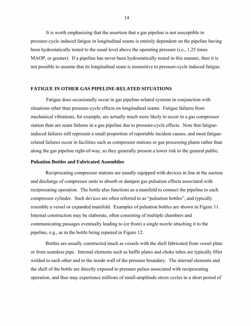
Pulsation Bottles and Fabricated Assemblies
Reciprocating compressor stations are usually equipped with devices in line at the suction
and discharge of compressor units to absorb or dampen gas pulsation effects associated with
reciprocating operation. The bottle also functions as a manifold to connect the pipeline to each
compressor cylinder. Such devices are often referred to as “pulsation bottles”, and typically
resemble a vessel or expanded manifold. Examples of pulsation bottles are shown in Figure 11.
Internal construction may be elaborate, often consisting of multiple chambers and
communicating passages eventually leading to (or from) a single nozzle attaching it to the
pipeline, e.g., as in the bottle being repaired in Figure 12.
Bottles are usually constructed much as vessels with the shell fabricated from vessel plate
or from seamless pipe. Internal elements such as baffle plates and choke tubes are typically fillet
welded to each other and to the inside wall of the pressure boundary. The internal elements and
the shell of the bottle are directly exposed to pressure pulses associated with reciprocating
operation, and thus may experience millions of small-amplitude stress cycles in a short period of

15
time. This type of loading spectrum makes the bottle durability or longevity highly dependent
on a number of factors. Such factors include:
• Engineering Design – Some design concepts present greater inherent fatigue susceptibility. For example, placing a stiff structural element such as a baffle plate directly under any one nozzle of a multiple inlet bottle may cause the bottle to become highly loaded at that nozzle due to a fit-up gap at any one flange, leading to chronic fatigue of the nozzle joint as in Figure 13.
• Design Details – The use of T-joints made with fillet-welds, Figure 14(a), instead of beveled or grooved full-penetration welds with a fillet overlay, Figure 14(b), saves fabrication time and cost. However, use of this detail in high-cycle applications (pulsation or vibration) may be counterproductive in the long run because the nonpenetrating or partially-penetrating fillet weld is inferior in fatigue resistance.
• Workmanship Flaws – Seemingly minor workmanship flaws such as weld toe undercut or poor weld bead profile drastically shorten the fatigue resistance of even a properly-specified weld detail.
• Shop Procedures – Failure to perform post-weld heat treatment of welds, or failure to prevent warping of the shell during heat treatment, can lead to premature failure of nozzles due to excessive local stresses. Failure to discard and replace all bolts used as structural attachments of internals following stress-relief heat treatment of the bottle can lead to bolt failure, causing internal components to become inadequately anchored and leading to excess vibration and failure in adjacent welds.
• Installation – Installation of bottles with misaligned nozzles or large nozzle gaps introduces high loads at the affected and adjacent nozzles, increasing stressing in flange welds, outlet welds, and the shell and reducing the threshold for fatigue crack initiation.
• Operating Conditions – Failure to adequately anchor attached piping can lead to failures in girth welds or nozzle fillet welds. Boring out a compressor cylinder can cause previously reliable pulsation bottles to experience chronic fatigue failures due to the increased magnitude of pressure pulsations.
Failures in pulsation bottles usually occur in or originate from the welded connections
between internal components, or between the bottle shell and internal or external attachments.
Leakage will occur where the cracks propagate into and through the shell. Usually pulsation
bottles are sufficiently low-stressed away from the local stress-raising detail that cracks remain
leaks, however, leaks can pose a hazard within the compressor building, necessitating a unit
shutdown and other actions. This normally does not pose a hazard off the compressor station
site such that the public would be affected, but leads to costly downtime and bottle repair.
Pulsation analysis programs are available for characterizing the pressure pulse frequencies and
amplitudes within the suction and discharge piping of a compressor unit.

16
Structural Vibration
Structural vibration of pipe produces alternating longitudinal bending stresses across the
pipe’s circular cross-section, leading to fatigue of pipe girth welds and branch attachments (not
to mention non-piping equipment such as instrument lines and compressor components, which
are beyond the scope of this discussion). Structural vibration could occur in some situations
involving above-ground pipeline segments, as described below.
Pulsation or Reciprocating Excitation
A significant proportion of reportable incidents that occur in compressor stations is
associated with the high-cycle fatigue effects of vibration caused by gas pulsation or
reciprocating action of compressors. A review of DOT-reportable incidents indicated 104 total
reportable incidents occurred in compressor stations between 1985 and 2000. Of these, 13
occurred in the reciprocating compressor units and associated equipment (e.g., pulsation bottles),
2 were failures in piping welds, and 12 were failures in small threaded fittings and tubing, so
26% were almost certainly due to the effects of pulsation or vibration arising from reciprocating
excitation.
Vibration effects are sometimes evident from visual observation, or from the occurrence
of repeated failures of components or attachments. Fillet-welded assemblies and unbraced
masses on cantilevers such as small valves teed off larger pipe runs may be particularly
susceptible. No consistent standard or criterion for evaluating the severity of vibrations in piping
is currently used in the industry, though criteria for evaluating vibration in piping do exist (e.g.,
Reference 12 for nuclear power plant piping). Piping affected by mechanical vibration issues
can be instrumented to provide information (deflections, accelerations, and pipe stresses) that
could be used in an engineering assessment such as the one given by Reference 12. Vibration
effects are mitigated by adequately bracing the pipe (though not in a manner that interferes with
flexibility required for thermal expansion), or controlling sources of vibration such as ineffective
pulsation bottles. A process for the systematic application of this approach could be developed if
a particular facility demonstrates the need.
Internal Flow-induced Vibration
The flow of gas inside piping can lead to vibration. Usually flow rates must be quite
high (in excess of 40 ft/sec) for turbulent flow within the pipe to cause much vibration.
However, even normal rates of flow can occasionally excite structures having low natural
17
frequencies, such as unbraced cantilevered masses. A typical cantilevered mass would be
represented by a small valve teed off a larger header. An example of a vibration-induced failure
in a 2-inch extruded outlet in a 30-inch header at the base of just such an arrangement is shown
in Figure 15. The source of vibration in this case had to be gas flow, since this incident occurred
at a turbine-powered compressor station where pulsation effects could not have been present, and
the header was part of a main line valve bypass assembly, most of which was buried and not
subjected to mechanical sources of vibration. Vibration effects are mitigated by adequately
bracing the pipe (though not in a manner that interferes with flexibility required for thermal
expansion), or controlling excessive gas flow rates.
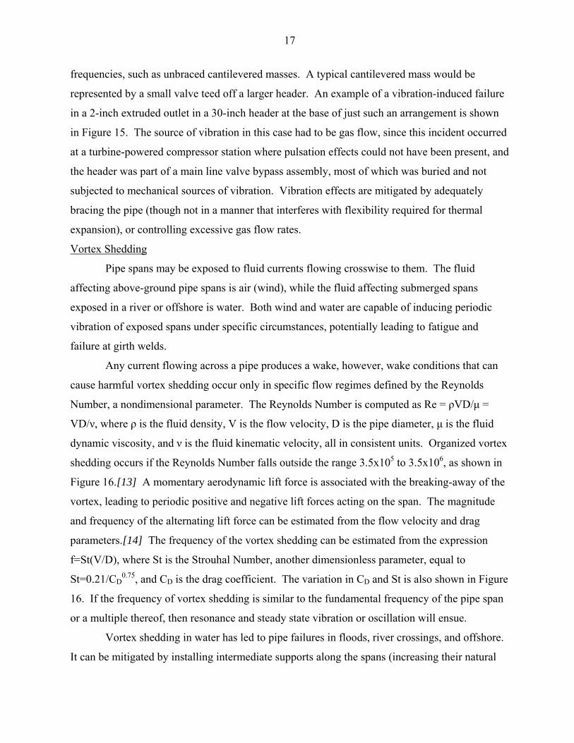
Vortex Shedding
Pipe spans may be exposed to fluid currents flowing crosswise to them. The fluid
affecting above-ground pipe spans is air (wind), while the fluid affecting submerged spans
exposed in a river or offshore is water. Both wind and water are capable of inducing periodic
vibration of exposed spans under specific circumstances, potentially leading to fatigue and
failure at girth welds.
Any current flowing across a pipe produces a wake, however, wake conditions that can
cause harmful vortex shedding occur only in specific flow regimes defined by the Reynolds
Number, a nondimensional parameter. The Reynolds Number is computed as Re = ρVD/µ =
VD/ν, where ρ is the fluid density, V is the flow velocity, D is the pipe diameter, µ is the fluid
dynamic viscosity, and ν is the fluid kinematic velocity, all in consistent units. Organized vortex
shedding occurs if the Reynolds Number falls outside the range 3.5x10⁵ to 3.5x10⁶, as shown in
Figure 16.[13] A momentary aerodynamic lift force is associated with the breaking-away of the
vortex, leading to periodic positive and negative lift forces acting on the span. The magnitude
and frequency of the alternating lift force can be estimated from the flow velocity and drag
parameters.[14] The frequency of the vortex shedding can be estimated from the expression
f=St(V/D), where St is the Strouhal Number, another dimensionless parameter, equal to
St=0.21/CD0.75, and CD is the drag coefficient. The variation in CD and St is also shown in Figure
16. If the frequency of vortex shedding is similar to the fundamental frequency of the pipe span
or a multiple thereof, then resonance and steady state vibration or oscillation will ensue.
Vortex shedding in water has led to pipe failures in floods, river crossings, and offshore.
It can be mitigated by installing intermediate supports along the spans (increasing their natural

18
frequency and reducing their dynamic response) or by burying the spans under an overburden
that is resistant to scouring. Vortex shedding in high wind has led to pipe failures above ground,
usually where the pipe is small in OD and encased in several inches of insulation, and support
spacing is regular. It can be mitigated by introducing irregular support spacing (so that no single
frequency dominates) or by attachment of passive aerodynamic devices (strakes) or active
mechanical vibration absorbers.
Thermal Expansion Loads
Although pressure governs the basic design (wall thickness and specified grade) of
pipelines and piping, the design and layout of above-ground piping systems must also consider
the effects of thermal expansion or other imposed deflection that produces bending stresses in
the pipe through flexure at changes in direction, branch points, and restraint points. Experience
and analysis has shown that flexibility associated with piping layout strongly influences the
magnitude of terminal reactions and the magnitude and distribution of bending moments
throughout the piping system. Many different piping flexibility analysis techniques have been
developed to enable the designer to assure that excess reactions at connected equipment, excess
stress levels in the pipe, and leakage at flanged joints will not occur. The flexibility analysis
estimates forces, moments, and stresses arising from thermal expansion or imposed
displacement, and compares them to allowable limits.
Flexibility analysis reveals that bends, branches, and anchors are where the highest
bending moments are likely to develop due to thermal expansion of the pipe. The geometry of
piping components produces a complex elastic response to bending loads transmitted to the
component through adjacent piping and anchors. This response usually results in local through-
wall bending stresses and changes in cross-section within the component resulting in greater
local flexibility and higher local stresses in the component than would occur in a piece of straight
pipe of the same nominal dimensions subjected to the same applied loading. Large or frequent
temperature changes associated with start-up and shut-down of processes may initiate fatigue in
a piping bend or branch. This risk may be the most important factor in evaluating the suitability
of a piping layout design in some types of process piping, independent of considerations for
pressure capacity and support of deadweight loadings.
The problem of stresses in fittings and components subject to thermal expansion cycles
cannot be successfully addressed without performing a flexibility analysis. The flexibility
19
analysis, providing a simplified fatigue evaluation of components, constitutes a vital step in the
design of above-ground piping found in process and power facilities. Markl’s seminal paper[15]
explains the rationale for the flexibility analysis and acceptance criteria (allowable stresses) as
established in the ASME B31 Code for Pressure Piping. Flexible above-ground piping systems
are essential features of pipeline compressor stations, gas dehydration and processing plants,
liquid product pump stations, and offshore platforms, and should be evaluated using methods
appropriate to such systems, which is to say methods similar to those used in laying out process
and power piping. Of course, flexibility is not an issue in a buried, restrained pipeline (with the
possible exception of bends in hot oil pipelines).
Structural Discontinuities
It was noted earlier that the fatigue initiation life is shortened if the local stresses are
increased by some type of geometric or metallurgical stress-concentrating feature. Stress-
concentrating effects associated with common features of pipelines and piping systems include:
• abrupt weld toe geometries or weld bead profiles;
• large differences in metal strength between deposited and base metals leading to localized differences in strain rates under load, which focuses strain in lower-strength grain structures;
• local bending stresses in the pipe wall (referred to as “discontinuity stresses”) due to differences in radial expansion under pressure of adjacent thick and thin shell segments; and
• major structural features such as branch openings.
The vast majority of welds and structural features in common use provide acceptable
service life when conventional standards for selection of design details and standards for welding
quality are observed. However, occasionally some combinations of design details in
combination with welding-related factors, all of which may be acceptable individually,
sufficiently enhance local stresses to result in the initiation and propagation of fatigue cracks.
Figure 17 shows a pair of fatigue cracks at the base of an unreinforced branch connection having
an excessively sharp weld profile in the crotch of the branch. Other structural details that can
occasionally give rise to fatigue include reinforcements or appurtenances that are much thicker
than the carrier pipe wall and that are attached by fillet welds, including nonintegral
reinforcements such as pads or sleeves, and self-reinforcing weld-on branch outlets (e.g., weld-o-
let style fittings).

20
ASME B31.8 specifies that reinforcement pads, saddles, or sleeves that are thicker than
the carrier pipe wall are to be tapered at their edges to the nominal pipe wall thickness, with fillet
weld leg dimensions about equal to the pipe wall thickness. The reason for this is that tests and
analysis have demonstrated that the juncture between drastic changes in thickness, and
specifically between thick reinforcements and thin pipe walls, leads to stress concentration and
susceptibility to fatigue.[16] While this edge tapering requirement results in a fillet weld throat
that is less than the wall thickness, this is not a problem because the fillet weld on nonintegral
reinforcement elements serves only as an attachment, not as a structural load-carrying weld.
Self-reinforcing weld-on fittings cannot be readily tapered because doing so would cut
into metal required for area replacement of the branch hole in the header. Figure 18 shows
several failures due to pressure-cycle fatigue adjacent to heavy-walled self-reinforcing branches
attached to thin-walled header pipe. Although these particular failures occurred in liquids
pipelines, the risk of fatigue or cycle-enhanced degradation (such as corrosion-fatigue or SCC) at
such sites in gas pipelines is possible. Failures in which pressure cycles played a role have
occurred at branches in gas pipelines. In some cases, it was known or suspected that other
structural loadings on the branch aside from the thrust due to internal pressure were also present.
This is not to suggest that all hot taps or branches pose a high fatigue risk. Observing the
good design and fabrication practices (e.g., those contained in the ASME B31 Code) greatly
reduces the concern for fatigue. On the other hand, experience has shown that heavy partial- or
full-encirclement reinforcements that have not been properly edge-tapered, and weld-on branch
fittings that are larger than ¼ of the header diameter in headers that operate at greater than 50%
of SMYS may be susceptible, particularly if some other adverse loading condition is present,
such as vibration or localized settlement.
Wrinkle Bends and Miters
Some older pipelines were constructed using wrinkle bends or miter bends for making
changes in direction of the pipeline. A wrinkle bend is a bend formed into a piece of initially
straight pipe where the inside of the bend features one or more prominent wrinkles deliberately
introduced as a means of foreshortening the inside meridian of the bend. A miter (or mitre) bend
is fabricated by cutting straight pipe segments off at an angle and joining one or more such
angled joints together to form a polygonal approximation of a bend. Neither wrinkle bends nor
21
miters are used in modern pipeline construction, although ASME B31.8 still permits them to be
used in new construction if the pipeline operates at a hoop stress of less than 30% of SMYS.
All bends embody geometric characteristics that tend to concentrate stresses due to
internal pressure or external bending moments, but wrinkle bends and miter bends contain more
acute stress concentrating features than an analogous smooth bends. This could in principle
make them more susceptible to fatigue from pressure cycles or thermal expansion cycles than
smooth bends. Ordinarily, this would still not be expected to raise much of a concern because
gas pipeline systems do not experience frequent pressure and temperature cycles. However, both
types of bend may contain initial defects that reduce their tolerance for operational cycles:
cracks due to excessive strains in the wrinkle bend, and workmanship defects in the miter bend
welds. Capacity to tolerate operational cycles may be further reduced if the wrinkle bend or
miter bend is capable of flexing in response to thermal expansion cycles as a result of being
buried in an incompetent soil.
Most wrinkle bends and miter bends that are operated in low-stress gas pipelines are
likely to be reliable, which is fortunate since hydrostatic testing or in-line inspection are unlikely
to be effective for singling out those bends that could someday cause a problem. The reason for
this is that wrinkle bends are more sensitive to longitudinal stresses imposed by external loadings
than the hoop stress due to internal pressure. Older pipelines containing wrinkle bends have
experienced failures of the bend, particularly in areas of soil movement. When such bends fail,
it is typically due to the effects of external loadings rather than as a result of internal pressure,
per se. Fatigue arising from fluctuations in operating pressure and temperature may play a role
in the observed sensitivity of some older wrinkle bends to axial loads, as might thermal
movement of sections of pipe following excavation. This remains a subject of study in the
industry. Where feasible, ILI can be useful in that geometry tools would indicate the location of
wrinkle bends and the magnitude of wrinkles.
A way to assess the condition of a given bend is to excavate it and perform
nondestructive examination for cracks in the wrinkle or weld defects in the miter. The
excavation destroys the consolidation and support for the bend, so any bend that is not cut out
and replaced with a modern smooth bend should probably be backfilled with a flowable fill that
can fully restrain the bend in place. Therefore, it makes little sense to excavate and mitigate
22
bends where there is no history of problems and no evidence of unusual external loadings being
present. Probably only those bends residing in a pipeline segment that has exhibited problems
with similar bends on prior occasions or that is located in a high consequence area would warrant
excavation and inspection.
Dents and Mechanical Damage
The term “dent” describes a permanent deformation of a pipe’s circular cross-section
caused by external forces. The curvature of the pipe wall within the dent may be reduced,
flattened, or reversed. A dent that has no scrapes, gouges, or other stress-concentrating features
present in conjunction with it is referred to as a “plain dent”. Dents caused by the installation of
a pipeline on rocks in the ditch are usually plain in nature; dents caused by excavating equipment
or other machinery striking a pipeline typically are not plain.
A dent that is prevented by the soil from pushing out (rerounding) under the influence of
internal pressure is a “constrained dent”. Rock-induced dents are typically constrained (unless
the pipeline is excavated). A dent that is free to push out under the influence of internal pressure
is unconstrained. Dents caused by excavating equipment typically are unconstrained. They
reround as the indenting equipment is withdrawn from the pipe surface. Once a dent is
excavated so that it can be examined, it is unconstrained regardless of whether it was constrained
or unconstrained prior to excavation.
The term “mechanical damage” refers to features such as gouges, scrapes, or crushed
metal introduced by contact from excavating or other mechanical equipment. Mechanical
damage typically exhibits one or more of the following features:
• visible scrape, gouge, or smeared metal;
• localized metal loss or reduced wall thickness not due to corrosion;
• cracking within a scrape or gouge; and
• creasing of the pipe wall, or a long narrow indentation.
The features listed above occurring in conjunction with pipe indentations are referred to by 49
CFR 192 as “stress concentrating features”. In most occurrences of mechanical damage, the pipe
undergoes indentation simultaneously with gouging of the metal surface. The indentation pushes
out (“rerounds”) under the influence of internal pipe pressure as the damaging object withdraws
23
from the pipe surface. The extent of rerounding depends on the pipe wall thickness, the pressure
in the pipe, and the initial dent geometry.
Tests have demonstrated that unrestrained plain dents having residual depths of 2% of the
pipe diameter or less, which is about what one would expect for an unrestrained dent after
rerounding, exhibited fatigue lives between 105 and 106 cycles of pressure producing hoop stress
levels between 36% and 72% of SMYS. This would likely be equivalent to infinite life for most
if not all gas pipelines. In fact, a fatigue failure in a plain shallow dent has never been reported
to have occurred in gas pipelines to the authors’ knowledge. As shown earlier, liquid pipelines
operate with pressure spectra that are far more severe than those of most gas pipelines, so
pressure fatigue in a plain dent may be possible in some liquid pipelines. This is supported by
service experience where fatigue cracks and leaks have occurred in liquid pipelines affected by
plain rock dents a few years after the rock has been removed.
Dents that are restrained, which would be the case for rock dents where the pipe has not
been excavated, have at least an order of magnitude greater fatigue life than unrestrained dents of
the same size and shape. In one series of tests, constrained dents as deep as 18% of the pipe
diameter survived hundreds of thousands of pressure cycles between 36% and 72% of SMYS
without failure.[17]
An important exception to the above findings is restrained rock-induced deformations
having two closely spaced centers of indentation with a flattened or saddle-shaped area between
them. It has been observed in service and in tests[18] that the flattened area between the two
dent centers is susceptible to pressure-cycle fatigue, because it is effectively unrestrained and
flexes readily in response to pressure cycles. As with other pressure-cycle fatigue situations
discussed already, incidents of this nature have been confirmed only in liquid pipelines.
The presence of metal damage caused by excavator teeth and the like changes the picture
completely. Such damaged metal would be susceptible to very low-cycle fatigue, which means
that a few cycles of high strain will cause a failure. Two mechanisms for the accumulation of
high strains is creep-like rerounding at high levels of sustained pressure, and shakedown of the
dent to elastic action over several pressure cycles. These mechanisms enable plastic strain,
which could be damaging to a strain-sensitive material, to continue to accumulate at the root of
the damage even with the steady pressures and infrequent large cycles that characterize gas
pipeline operations. This seems to adequately explain how pressure reversals and delayed
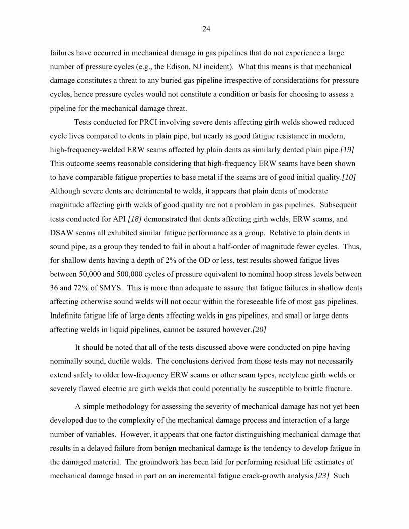
24
failures have occurred in mechanical damage in gas pipelines that do not experience a large
number of pressure cycles (e.g., the Edison, NJ incident). What this means is that mechanical
damage constitutes a threat to any buried gas pipeline irrespective of considerations for pressure
cycles, hence pressure cycles would not constitute a condition or basis for choosing to assess a
pipeline for the mechanical damage threat.
Tests conducted for PRCI involving severe dents affecting girth welds showed reduced
cycle lives compared to dents in plain pipe, but nearly as good fatigue resistance in modern,
high-frequency-welded ERW seams affected by plain dents as similarly dented plain pipe.[19]
This outcome seems reasonable considering that high-frequency ERW seams have been shown
to have comparable fatigue properties to base metal if the seams are of good initial quality.[10]
Although severe dents are detrimental to welds, it appears that plain dents of moderate
magnitude affecting girth welds of good quality are not a problem in gas pipelines. Subsequent
tests conducted for API [18] demonstrated that dents affecting girth welds, ERW seams, and
DSAW seams all exhibited similar fatigue performance as a group. Relative to plain dents in
sound pipe, as a group they tended to fail in about a half-order of magnitude fewer cycles. Thus,
for shallow dents having a depth of 2% of the OD or less, test results showed fatigue lives
between 50,000 and 500,000 cycles of pressure equivalent to nominal hoop stress levels between
36 and 72% of SMYS. This is more than adequate to assure that fatigue failures in shallow dents
affecting otherwise sound welds will not occur within the foreseeable life of most gas pipelines.
Indefinite fatigue life of large dents affecting welds in gas pipelines, and small or large dents
affecting welds in liquid pipelines, cannot be assured however.[20]
It should be noted that all of the tests discussed above were conducted on pipe having
nominally sound, ductile welds. The conclusions derived from those tests may not necessarily
extend safely to older low-frequency ERW seams or other seam types, acetylene girth welds or
severely flawed electric arc girth welds that could potentially be susceptible to brittle fracture.
A simple methodology for assessing the severity of mechanical damage has not yet been
developed due to the complexity of the mechanical damage process and interaction of a large
number of variables. However, it appears that one factor distinguishing mechanical damage that
results in a delayed failure from benign mechanical damage is the tendency to develop fatigue in
the damaged material. The groundwork has been laid for performing residual life estimates of
mechanical damage based in part on an incremental fatigue crack-growth analysis.[23] Such

25
analysis is still somewhat experimental since methods for accounting for the initial damage
severity, effect of indentation geometry, and other parameters have not been reduced to routine
or standardized techniques.
Environmental Cracking
An environmentally-induced crack may become enlarged by fatigue. Stress-corrosion
cracking (SCC) is a form of environmentally assisted cracking that occasionally can occur in line
pipe steels under known conditions. Moderate to high tensile stresses are required, as is some
cycling of the stress in order to reexpose the crack-tip to the adverse environment. When SCC
occurs in a liquids pipeline, pressure-cycle fatigue usually can be expected to take over as the
mechanism for crack enlargement from the original stress-corrosion crack, after a time. In some
rare instances, this appears to have occurred in gas pipelines.
Figure 19 shows a fatigue crack that extended from a small stress-corrosion crack at the
weld toe adjacent to a reinforcement saddle for a 16-inch branch on a 26-inch OD natural gas
pipeline. The coating around the branch was wax, which can shield the pipe from effective CP if
it becomes disbonded from the pipe surface. The pipeline operated at 45% of SMYS and
experienced a pressure operation not as severe as what is shown in Figure 4. Although the local
stresses in the pipe wall at the “hillside” location adjacent to a reinforcement saddle are enhanced
by a stress-concentrating effect (refer to the discussion on structural discontinuities), the saddle
assembly would ordinarily have been expected to tolerate on the order of 22,000 cycles based on
pressure-fatigue tests of similar configurations and, therefore, would not have been expected to
have a service life limited by fatigue.[21]
Figure 20 shows a cross-section of a DSAW longitudinal seam in a 36-inch natural gas
pipeline. The seam contains a fatigue crack that extended from a stress-corrosion crack that
originated at the toe of the seam. The coating was asphalt and the affected area was positioned
under a concrete river weight in a peat bog. The pipeline operated at 69% of SMYS. Note that
the outer seam bead was deposited far enough off-center to expose part of the welder tracking
groove and produce an acute weld toe. The bending moment couple established by the offset
bead, combined with the abrupt toe geometry, significantly concentrated the local stresses
compared to a normal DSAW seam profile, enhancing susceptibility to both SCC and the
subsequent fatigue.

26
In both of these cases involving natural gas transmission mainlines, the effects of
pressure cycles promoted the occurrence and enlargement of cracking in service. However, as is
the case with enlargement of cracks present in mechanical damage, other factors had to first be
present for this to occur. Therefore, considerations for pressure cycling would not be the
primary basis for either assessing the risk of SCC or for developing a mitigation plan for that
risk.
Hydrogen-induced cracking (HIC) is associated with the environment present during
welding, under certain conditions. The cracking results from hydrogen produced by the use of a
cellulosic (non-low-hydrogen) welding process being trapped in the weld, in conjunction with
base materials having sufficient chemistry content to produce a heat-affected zone having a hard,
coarse-grained microstructure when exposed to a high weld-cooling rate. Like SCC, HIC can
serve as an initiation site for crack growth in service due to fatigue. The application of
appropriate production and in-service welding procedures substantially reduces the risk of HIC
and subsequent concern for flaw extension in service.
IMPLICATIONS FOR INTEGRITY MANAGEMENT PLANNING
Keeping the Fatigue Threat in Perspective
The foregoing discussion described a few situations in which fatigue can present a threat
to the integrity of gas pipelines or related systems, under some circumstances. It is important to
keep this threat in perspective with the overall set of threats that could affect gas pipelines.
Encroachment damage and corrosion account for a majority of significant gas pipeline incidents.
Fatigue does not play a causal role in those incidents in that the root cause was the pipeline
becoming damaged, and without which no fatigue would occur. (Low-cycle fatigue in the
damaged material may be a key factor distinguishing mechanical damage that causes a delayed
failure and benign mechanical damage, however.) The balance of incident causes consists of
natural events, incorrect operation, pipe and seam defects, fabrication defects, and non-pipe
equipment failures. Fatigue does not play a role in pipe and seam defect incidents in gas
pipelines, and it would not be expected to be a factor in operator error. The remaining categories
account for not much more than 20% of reportable incidents, and fatigue is not their only
potential root cause. Even within compressor stations, which are the gas facilities most

27
susceptible to fatigue effects, only about one-quarter of reportable incidents appear to be
attributable to fatigue. So fatigue is involved in a relatively small proportion of reportable or
significant incidents in gas pipelines.
Integrity Management Planning Requirements
Paragraph 192.917(e)(2) states the following:
“(2) Cyclic fatigue. An operator must evaluate whether cyclic fatigue or other loading condition (including ground movement, suspension bridge condition) could lead to a failure of a deformation, including a dent or gouge, or other defect in the covered segment. An evaluation must assume the presence of threats in the covered segment that could be exacerbated by cyclic fatigue. An operator must use the results from the evaluation together with the criteria used to evaluate the significance of this threat to the covered segment to prioritize the baseline assessment.”
The preamble to the original regulation introducing Subpart O and the above paragraph states:
“Particular threats. The rule requires that an operator take specific actions to address particular threats the operator has identified. Those threats, and the required actions, are for third-party damage, cyclic fatigue, manufacturing and construction defects, ERW or lap welded pipe, and corrosion. These threats have been identified for specific action because of their significance to pipeline integrity and because the operational characteristics of gas transmission pipelines dictate that they be treated uniquely. The primary difference in the operation of gas transmission pipeline related to these defects is the absence of significant pressure cycling and the associated absence of the cyclic fatigue driving force for crack growth. The absence of significant cyclic fatigue implies that the failure of pipelines from these threats has unique causes that need to be address in an integrity management program for gas transmission pipelines.”
The authors of the regulation evidently recognized that the operating pressure cycles in
gas pipelines do not constitute the degree of threat seen in certain liquid pipelines, particularly
with respect to longitudinal seams. Therefore, this clause of the regulation must be concerned
about issues other than pressure-cycle effects on long seams. Clues are given by the fact that
192.917(e)(2) refers to “other loading conditions” (although not all examples it cites are cyclical
in nature) and refers to deformations or other defects. Figure 21 presents an example of a simple
framework for addressing some of the concerns raised in 192.917(e)(2). (The authors and
distributors of this report point out that this process may or may not be suitable for all gas
pipeline systems. It has not been reviewed or approved by the Office of Pipeline Safety.
Incorporation of this process into an Integrity Management Plan does not assure compliance with

28
regulatory provisions. It has been included herein to illustrate a systematic approach to
addressing some of the provisions and threat components listed in 192.917(e)(2).)
The first box establishes criteria for identifying whether pressure cycles could affect a
dent. It was established earlier that pressure cycles do not present much of a concern with the
majority of dents in gas pipelines. The criterion requires that a pipeline operate at 50% or more
of SMYS and experience pressure cycles (peak to valley magnitude) equal to 80% of the MAOP
on a daily basis in order for pressure cycles to be a concern with dents. This would exclude the
vast majority of gas pipelines, but if the result is positive, then a deformation assessment (by ILI)
would be warranted. Obviously, there are likely to be other and better reasons for performing a
deformation assessment on many pipelines, so this process would lead to very few assessments
for the presence of deformations solely on the basis of pressure cycles during operation, or
assessments for deformations that would not be performed anyway.
The process then investigates for susceptibility of buckles or wrinkles, and subsequently
girth welds and branch connections, to potentially threatening loading scenarios other than
pressure cycles. Some of the loadings are cyclical in nature and some are not. If adverse
conditions are present, then an assessment for the presence of such features is warranted.
Methods of assessment may be other than the standard methods of hydrostatic testing, in-line
inspection, or direct assessment. For example, an assessment for buckles might consist of ILI to
detect the presence of a buckle, followed by excavation and nondestructive examination of the
buckle to verify an absence of cracks. An assessment of welds on a span across a ditch might
consist of an engineering analysis to determine whether the span could be submerged by flood
level water flow and for susceptibility to vortex shedding, and if appropriate, radiography of
welds not previously inspected at the time of construction.
Situations that apply primarily in reciprocating compressor stations such as pulsation
bottles and mechanical vibration were not included because the majority of compressor stations
are in relatively sparsely-populated areas, most compressor buildings are equipped to vent gas or
detect and combat fires, and most compressor stations have generous buffer areas that would
reduce the hazard to the public in the event of a fire in the compressor building. Also, many
compressor facilities are designed to accommodate cyclic service, and compressor station piping
is limited to operating stresses of 50% of SMYS or less.
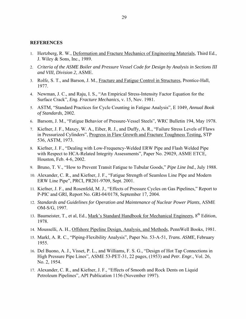
29
REFERENCES
1. Hertzberg, R. W., Deformation and Fracture Mechanics of Engineering Materials, Third Ed., J. Wiley & Sons, Inc., 1989.
2. Criteria of the ASME Boiler and Pressure Vessel Code for Design by Analysis in Sections III and VIII, Division 2, ASME.
3. Rolfe, S. T., and Barson, J. M., Fracture and Fatigue Control in Structures, Prentice-Hall, 1977.
4. Newman, J. C., and Raju, I. S., “An Empirical Stress-Intensity Factor Equation for the Surface Crack”, Eng. Fracture Mechanics, v. 15, Nov. 1981.
5. ASTM, “Standard Practices for Cycle Counting in Fatigue Analysis”, E 1049, Annual Book of Standards, 2002.
6. Barsom, J. M., “Fatigue Behavior of Pressure-Vessel Steels”, WRC Bulletin 194, May 1978.
7. Kiefner, J. F., Maxey, W. A., Eiber, R. J., and Duffy, A. R., “Failure Stress Levels of Flaws in Pressurized Cylinders”, Progress in Flaw Growth and Fracture Toughness Testing, STP 536, ASTM, 1973.
8. Kiefner, J. F., “Dealing with Low-Frequency-Welded ERW Pipe and Flash Welded Pipe with Respect to HCA-Related Integrity Assessments”, Paper No. 29029, ASME ETCE, Houston, Feb. 4-6, 2002.
9. Bruno, T. V., “How to Prevent Transit Fatigue to Tubular Goods,” Pipe Line Ind., July 1988.
10. Alexander, C. R., and Kiefner, J. F., “Fatigue Strength of Seamless Line Pipe and Modern ERW Line Pipe”, PRCI, PR201-9709, Sept. 2001.
11. Kiefner, J. F., and Rosenfeld, M. J., “Effects of Pressure Cycles on Gas Pipelines,” Report to P-PIC and GRI, Report No. GRI-04/0178, September 17, 2004.
12. Standards and Guidelines for Operation and Maintenance of Nuclear Power Plants, ASME OM-S/G, 1997.
13. Baumeister, T., et al, Ed., Mark’s Standard Handbook for Mechanical Engineers, 8th Edition, 1978.
14. Mousselli, A. H., Offshore Pipeline Design, Analysis, and Methods, PennWell Books, 1981.
15. Markl, A. R. C., “Piping-Flexibility Analysis”, Paper No. 53-A-51, Trans. ASME, February 1955.
16. Del Buono, A. J., Visset, P. L., and Williams, F. S. G., “Design of Hot Tap Connections in High Pressure Pipe Lines”, ASME 53-PET-31, 22 pages, (1953) and Petr. Engr., Vol. 26, No. 2, 1954.
17. Alexander, C. R., and Kiefner, J. F., “Effects of Smooth and Rock Dents on Liquid Petroleum Pipelines”, API Publication 1156 (November 1997).

30
18. Kiefner, J. F., and Alexander, C. R., “Effects of Smooth and Rock Dents on Liquid Petroleum Pipelines (Phase 2)”, Addendum to API Publication 1156, October 1999.
19. Fowler, J. R., Alexander, C. R., Kovach, R. J., and Connelly, L. M., “Cyclic Pressure Fatigue Life of Pipelines with Plain Dents, Dents with Gouges, and Dents with Welds”, A.G.A. Catalog No. L51705 (June 1994).
20. Rosenfeld, M. J., “Toward an Acceptance Criterion for Shallow Dents Affecting Girth Welds in Gas Transmission Pipelines”, PVP Vol. 353, ASME Pressure Vessel and Piping Conference, Orlando (July 1997).
21. Rodabaugh, E. C., “Review of Service Experience and Test Data on Openings in Pressure Vessels with Non-Integral Reinforcement”, WRC Bulletin 166, October 1971.
22. National Transportation Safety Board, “Rupture of Enbridge Pipeline and release of Crude Oil near Coasset, Minnesota July 4, 2002”, Pipeline Accident Report, NTSB/PAR-04/01, June 23, 2004.
23. Rosenfeld, M. J., “Proposed New Guidelines for ASME B31.8 on Assessment of Dents and Mechanical Damage”, GRI-01/0084, May 2001.

FIGURES

This Page Intentionally Left Blank
31
(a)
(b)
Figure 1 – ASME Fatigue S-N Data and Design Curve

32
Figure 2 – Typical Fatigue Failure Fracture Surface
Figure 3 – Simplified Crack Model
300
400
500
600
700
800
900
1000
0 50 100 150 200 250 300 350 400 450
Number of Days
Pres
sure
, psi
g
Figure 4 – Aggressive Gas Pipeline Operating Spectrum

33
Figure 5 – Crack Propagation in Service
Figure 6 – Some Typical Crack Growth Rate Data for Carbon Steel

34
(a)
(b) Figure 7 – Fatigue Crack Originating from ERW Seam Hook Crack
(a)
(b)
Figure 8 – Rail Shipment Fatigue Crack at Toe of DSAW Seam

35
0
200
400
600
800
1000
1200
1400
1600
1800
0 50 100 150 200 250
Number of Days
Pres
sure
(psi
g)
Figure 9 – Aggressive Liquid Pipeline Operating Spectrum
0
200
400
600
800
1000
1200
1400
1600
1800
0 50 100 150 200 250
Number of Days
Pres
sure
, psi
g
Figure 10 – Gas Pipeline Operating Spectrum (from Fig. 4, Rescaled)

36
Figure 11 – Pulsation Bottles

37
Figure 12 – Pulsation Bottle Internals Undergoing Repair

38
Figure 13 – Bottle Shell Crack Due to Design Fault
(a)
(b)
Figure 14 – T-Joint Weld Details

39
Figure 15 – Structural Vibration Failure in Gas Pipeline Extruded Outlet

40
Figure 16 – Flow Regimes Susceptible to Vortex Shedding
Figure 17 – Fatigue Cracks at Poor Weld Profile on Branch Connection
41
Figure 18 – Example Fatigue Failures Adjacent to Heavy-Walled Attachments

42
Figure 19 – Fatigue Crack Extending from SCC at Toe of Saddle Weld
Figure 20 – Fatigue Crack Extending from SCC at Toe of DSAW Seam

43
No
Yes
Exit192.917(e)(2)
process.
No
Yes
Section 192.917(e)(2)"Cyclic Fatigue"
Process
Are dent fatigue sensitiveoperating conditions present?
Schedule baselineassessment for dents
and mechanical damage
Wrinkle/Buckle Sensitivity EvaluationReview HCA for presence of the followingconditions:
SubsidenceSoil movementSlope instabilityPipe exposed in water crossingsPipelines on bridgesFree spans across ditches
Are wrinkle/buckle fatiguesensitive conditions present?
Schedule baselineassessment for buckles
or wrinkles
Dent Fatigue Sensitivity EvaluationReview HCA for Class 1, 2, or 3 operationthat experiences pressure cycles of 80% ofMAOP or larger at least once per day
Other Defect Fatigue SensitivityEvaluationReview HCA for presence of thefollowing conditions:
Pipe exposed in water crossingsPipelines on bridgesFree spans across ditchesCantilevered valves and stacks
Are other defect fatigue ssensitive conditions present?
Schedule assessmentcapable of detecting girth
weld or branch welddefects (see Note 1)
Yes
No
Note 1 -- MFL ILI and radiography (RT) aresuitable NDT methods for detectingsignificant flaws in girth welds. RT andmagnetic particle exam (MT) are suitableNDT methods for detecting significant flawsin branch welds.
Disclaimer: The authors and distributors of this report make no warranty that this process is suitable for all natural gas pipelines for purposes of regulatory compliance.
Figure 21 – Example Process for Addressing 192.917(e)(2)

This Page Intentionally Left Blank

This Page Intentionally Left Blank

Copyright, 2006 All Rights Reserved by Pipeline Research Council International, Inc.
PRCI Reports are Published by Technical Toolboxes, Inc.
3801 Kirby Drive, Suite 340 Houston, Texas 77098 Tel: 713-630-0505 Fax: 713-630-0560 Email: [email protected]


![115 A Review of Fatigue Crack Growth for Pipeline Steels ... · Possible effects of hydrogen on fatigue cracking behavior (from [14, 15]) (),m da AK dN =Δ Fig. 2. Schematic illustration](https://static.fdocuments.in/doc/165x107/5ed7aad45ab86c3b0273a11f/115-a-review-of-fatigue-crack-growth-for-pipeline-steels-possible-effects-of.jpg)