AutoCAD - Faculty Webfaculty.ivytech.edu/~bl-desn/dsn103/images/Windows... · Working with AutoCAD...
42
Working with AutoCAD Files Learning Objectives After completing this chapter, you will be able to do the following: ⇒ Explain the meaning and use of Windows file extensions. ⇒ Select, display, and arrange folders and files in Windows Explorer. ⇒ Manage files and folders using Windows Explorer. ⇒ Search for files and folders using Windows Explorer. ⇒ Copy, move, delete, and rename files using Windows Explorer. ⇒ Format and copy diskettes using Windows Explorer. ⇒ Perform drag-and-drop operations using Windows Explorer. ⇒ Manage critical files using the Options dialog box. ⇒ Import and export a variety of file types in AutoCAD. AutoCAD works with several types of computer files. The files are identi- fied by a three-letter file extension at the end of the file name. Windows Explorer provides a variety of tools to help you manage these files and the folders where they are stored. This chapter covers many of those functions. AutoCAD can write drawing files in a variety of formats, many of which are compatible with other popular software applications. You can export the industry standard DXF file for use with other CAD packages or specific applications. Files can also be exported for use in the design and animation software programs Autodesk VIZ and 3ds max, or for use in rapid prototyping processes such as stereolithography. In addition, you can import several different file types into AutoCAD. Types of File Names Drawing file names can be up to 255 characters long. They can contain let- ters, numbers, spaces, dollar signs ($), hyphens (-), and underscores (_). When you begin a new drawing, AutoCAD adds a file extension to the end of the file name. This extension is .dwg. If you name a drawing Building 340, AutoCAD Copyright by Goodheart-Willcox Co., Inc. Windows Explorer, page 1 and its applications AutoCAD BASICS Student CD Student CD WINDOWS WINDOWS EXPLORER EXPLORER WINDOWS EXPLORER
Transcript of AutoCAD - Faculty Webfaculty.ivytech.edu/~bl-desn/dsn103/images/Windows... · Working with AutoCAD...

Working with AutoCAD FilesLearning Objectives
After completing this chapter, you will be able to do the following:⇒ Explain the meaning and use of Windows file extensions.⇒ Select, display, and arrange folders and files in Windows Explorer.⇒ Manage files and folders using Windows Explorer.⇒ Search for files and folders using Windows Explorer.⇒ Copy, move, delete, and rename files using Windows Explorer.⇒ Format and copy diskettes using Windows Explorer.⇒ Perform drag-and-drop operations using Windows Explorer.⇒ Manage critical files using the Options dialog box.⇒ Import and export a variety of file types in AutoCAD.
AutoCAD works with several types of computer files. The files are identi-fied by a three-letter file extension at the end of the file name. WindowsExplorer provides a variety of tools to help you manage these files and thefolders where they are stored. This chapter covers many of those functions.
AutoCAD can write drawing files in a variety of formats, many of which arecompatible with other popular software applications. You can export the industrystandard DXF file for use with other CAD packages or specific applications. Filescan also be exported for use in the design and animation software programsAutodesk VIZ and 3ds max, or for use in rapid prototyping processes such asstereolithography. In addition, you can import several different file types intoAutoCAD.
Types of File NamesDrawing file names can be up to 255 characters long. They can contain let-
ters, numbers, spaces, dollar signs ($), hyphens (-), and underscores (_). Whenyou begin a new drawing, AutoCAD adds a file extension to the end of the filename. This extension is .dwg. If you name a drawing Building 340, AutoCAD
Copyright by Goodheart-Willcox Co., Inc. Windows Explorer, page 1
and its applicationsAutoCADB A S I C SStudent CDStudent CD
WINDOWSWINDOWSEXPLOREREXPLORERWINDOWSEXPLORER

adds the extension to create the file name of Building 340.dwg. When you openthe drawing to edit, you only have to type Building 340. AutoCAD knows to lookfor that file, plus the .dwg extension. File names are not case-sensitive. Thismeans you can name a drawing PROBLEM 20-12, but Windows interpretsProblem 20-12 as the same file name. See Figure WE-1.
After you edit the Building 340.dwg file and save it again, the original is con-verted to a backup file. Its file extension is automatically changed to .bak(backup). AutoCAD maintains a current DWG file and one BAK file. If yourevise and save the Building 340 drawing again, the BAK file is erased and theprevious DWG file becomes the backup. Only a newly revised drawing isgiven the .dwg file extension. AutoCAD 2005 drawing files have the samestructure as AutoCAD 2004 drawing files, therefore you will not see a specificAutoCAD 2005 drawing file type listed in the “Files of type:” drop-down list.The same can be said of the DXF file format which is discussed later in thischapter.
Copyright by Goodheart-Willcox Co., Inc. Windows Explorer, page 2
and its applicationsAutoCADB A S I C SStudent CDStudent CD
WINDOWSWINDOWSEXPLOREREXPLORERWINDOWSEXPLORER
Existing filename
New filename
Figure WE-1. File names are not case sensitive. This alert box appears whenyou attempt to save as an already existing file.

Some common file extensions used by AutoCAD and Windows include thefollowing:
Copyright by Goodheart-Willcox Co., Inc. Windows Explorer, page 3
and its applicationsAutoCADB A S I C SStudent CDStudent CD
WINDOWSWINDOWSEXPLOREREXPLORERWINDOWSEXPLORER
PROFESSIONALTIP Saving backup files is the default behavior of AutoCAD.
This feature is controlled by the Create backup copy with each save option in the File Safety Precautions area of the Open and Save tab of the Options dialog box. The creation of backup files can be disabled to reduce the amount of time required to save, but this is not advised for most applications. If a drawing file becomes corrupt, a backup file may be the only way to recover data that would otherwise be lost. Recovering lost or damaged drawing data is discussed later in this chapter.
WINDOWSBMP Bitmap fileCLP Windows Clipboard fileCOM Command fileDLL Dynamic-link library fileEXE Executable fileINI Initialization fileWMF Windows metafile
AutoCADBAK Backup copy of a drawing fileDCL Dialog control language description fileDST Drawing sheet setDWF Design web formatDWG Drawing fileDWT Drawing template fileLIN File containing the linetypes used by AutoCADMNU Menu source filePAT Hatch patterns filePLT Plot file

Introduction to Windows ExplorerWindows Explorer is a program used to manage and display folders and
files. To activate Windows Explorer, right-click the Start menu button andselect Explore from the shortcut menu.
Elements of Windows ExplorerWhen you use Windows Explorer, you will see the contents of the current
drive displayed as a directory tree. The directory tree is a graphic representa-tion of the directory structure and the folders and files it contains. When youstart Windows Explorer, the window displays the contents of the currentdrive. See Figure WE-2. The window is divided in half with a vertical splitbar. The left half of the window, referred to as the folders pane, displays thedirectory tree. The right half of the window, the contents pane, lists the con-tents of the current folder. You can drag the split bar to the left or to the rightto display more or less of the contents in each side of the window.
At the right of the window is a list of the folders and files contained in theselected folder. A folder icon appears next to each folder in this list. A file iconindicating the file type appears next to each file name. Program files (EXE andBAT files), document files (TXT and DOC files), and other types of files areeach represented with a specific icon.
Copyright by Goodheart-Willcox Co., Inc. Windows Explorer, page 4
and its applicationsAutoCADB A S I C SStudent CDStudent CD
WINDOWSWINDOWSEXPLOREREXPLORERWINDOWSEXPLORER
The functions of the Windows Explorer are very similar in Windows NT, Windows 2000, and Windows XP. However, there are some minor differences. This chapter is based on the Windows Explorer provided with Windows XP. The material in the chapter is still applicable if you are using a different operating system, but the window may appear slightly different.
NOTEWhen AutoCAD is configured to display a screen menu, the commands appear in a separate screen.
Refer to the File Management reference material on the Student CD for important information on hard disk structure and management. This information is applicable to any classroom or business application.
NOTEWhen AutoCAD is configured to display a screen menu, the commands appear in a separate screen.

You must first select a file or folder in Windows Explorer before you canwork with it. When you want to select a file or folder, place the cursor over thedesired file or folder icon and pick. You can select more than one file or folderby pressing and holding the [Ctrl] key as you pick with your pointing device.The items you select are highlighted. Any operations you perform are appliedto the selected files and folders. More information about file and folder selectionappears later in this chapter.
Drive icons represent each of the drives on your computer. These are listedbelow the My Computer icon near the top of the list in the folders pane. SeeFigure WE-3. The text to the right of each icon lists the label and the drive let-ter for each drive. Each type of drive is represented by a different icon. You can
Copyright by Goodheart-Willcox Co., Inc. Windows Explorer, page 5
and its applicationsAutoCADB A S I C SStudent CDStudent CD
WINDOWSWINDOWSEXPLOREREXPLORERWINDOWSEXPLORER
Address text box displayspath to selected folder
Status bar displays informationabout selected file or folder
Contents ofselected folder displayed
in contents pane
Title barDirectorytree displayed in
folders pane
Selectedfolder
Splitbar
Figure WE-2The folders pane of Windows Explorer displays the directory tree, while thecontents pane displays the files and subfolders within the selected folder.

see the diskette drive (A:) is represented with a different icon from those usedfor the hard disks (C: and T:). To work with the contents of one of the availabledrives, pick the desired drive icon. This displays the drive’s contents in thepane on the right.
Just below the Windows Explorer title bar are pull-down menus. Themenus displayed depend on your operating system. Many of the commandslocated in these menus are explored later in this chapter.
Finally, as with all Microsoft Windows applications, Windows Explorer canbe moved, resized, closed, and minimized to the taskbar at any time. Standardmethods are used to perform these activities.
Accessing Windows Explorer CommandsMost commands used in Windows Explorer can be accessed in several
ways. Commands can be activated from a toolbar button, pull-down menu, orshortcut menu. Some commands can also be accessed through keyboardshortcuts.
Copyright by Goodheart-Willcox Co., Inc. Windows Explorer, page 6
and its applicationsAutoCADB A S I C SStudent CDStudent CD
WINDOWSWINDOWSEXPLOREREXPLORERWINDOWSEXPLORER
Driveicons
Figure WE-3.Drive icons are listed under the My Computer icon.

Toolbar buttons enable you to perform a variety of functions quickly. Thetoolbar display is toggled on and off by selecting an option from the Toolbarscascading menu of the View pull-down menu. A check mark next to a toolbarname indicates it is active.
Figure WE-4 provides quick identification of the default toolbar availablein Windows Explorer. The functions of these buttons are described later inthis chapter when applicable. Additional functions can be added to the tool-bar by selecting Customize… from the Toolbars cascading menu in the Viewpull-down menu.
Listing Folders and FilesThe default appearance of Windows Explorer is similar to that shown in
Figure WE-2. The window is composed of the title bar, pull-down menu bar,standard toolbar, Address text box, Links bar, folders pane, contents pane, andstatus bar. The Links bar is not active by default.
Copyright by Goodheart-Willcox Co., Inc. Windows Explorer, page 7
and its applicationsAutoCADB A S I C SStudent CDStudent CD
WINDOWSWINDOWSEXPLOREREXPLORERWINDOWSEXPLORER
Go back toprevious folder
Go up one folder
Toggles display ofthe folders pane
Copy selected filesto a different folder
Undo lastoperation
Return aftergoing back
Search for files
Move selected filesto a different folder
Delete selected files
Change view stylein contents pane
Figure WE-4.Many file management options are available in the Windows Explorer toolbar.
The terms folder and directory are used interchangeably and mean the same thing.
NOTEWhen AutoCAD is configured to display a screen menu, the commands appear in a separate screen.

Folder and device icons in the folders pane may be preceded by a small boxcontaining a “+” or a “–” symbol. The + indicates the folder contains additionalfolders, or subfolders. Picking the + symbol expands the tree to display thenext level of folders. You can collapse, or hide, the display of these subfoldersby picking the “–” symbol.
Folders are opened in the folders pane with a single pick on the icon. Thefolder contents are displayed in the contents pane. Folders in the contentspane must be double-clicked to open. An open folder is automatically closedwhen a new one is selected and opened.
The contents of a folder can be viewed in several different ways. These arefound in the View pull-down menu. The current display method is indicatedby a dot to the left of the name. The following display options are illustratedin Figure WE-5:
• Thumbnails. Displays icons for files and folders in large format. If afolder contains graphics files, thumbnail images of those files are displayed on the folder icon.
• Tiles. Displays each folder or file icon in a large format with the filename and selected information below it.
Copyright by Goodheart-Willcox Co., Inc. Windows Explorer, page 8
and its applicationsAutoCADB A S I C SStudent CDStudent CD
WINDOWSWINDOWSEXPLOREREXPLORERWINDOWSEXPLORER
NOTE When installing AutoCAD, the default location of the AutoCAD 2005 folder is in the Program Files folder. However, the location and name of the AutoCAD 2005 folder can be easily changed during installation and may not agree with the default settings. If you are unsure of the name or location of the AutoCAD folder, ask your instructor or supervisor.
When AutoCAD is configured to display a screen menu, the commands appear in a separate screen.
PROFESSIONALTIP When the directory tree is expanded to several levels, you
can quickly back up to the previous level or branch by picking the Back button or by pressing the [Backspace] key.

• Icons. Displays each folder and file icon in medium-size format withthe folder or file name beneath it.
• List. Represents files and folders with small icons with file names tothe right. The list fills the height of the contents pane. Files that do notfit in the first column are listed in additional columns to the right. Usethe horizontal scroll bar to display them.
• Details. Displays folders and files as a single column of small icons.The file name, size, type, and the date and time the file was last modi-fied are listed to the right of each icon. Additional details can be addedusing the Choose Details… option in the View pull-down menu.
Copyright by Goodheart-Willcox Co., Inc. Windows Explorer, page 9
and its applicationsAutoCADB A S I C SStudent CDStudent CD
WINDOWSWINDOWSEXPLOREREXPLORERWINDOWSEXPLORER
Tiles
Icons
Details List
Thumbnails
Figure WE-5.There are several ways to have files listed in the contents pane.

These view options can also be selected using the Views button at the right sideof the toolbar. Selecting the Views button accesses a drop-down list of the options.Viewing and arranging options can also be selected by right-clicking on any openarea of the contents pane and selecting an option from the shortcut menu.
Basic Windows Explorer FunctionsBefore using the Windows Explorer to manage your folders and files, it is
best to have a good understanding of how these items are selected and whatkinds of actions Windows Explorer is capable of performing.
Copyright by Goodheart-Willcox Co., Inc. Windows Explorer, page 10
and its applicationsAutoCADB A S I C SStudent CDStudent CD
WINDOWSWINDOWSEXPLOREREXPLORERWINDOWSEXPLORER
If you need to print a list of file names, Windows does not provide a direct way of doing this. However, this can be accomplished using some commands and switches within a Command Prompt window. Do the following:1. Open Windows Explorer to a folder that contains some files, perhaps where your AutoCAD drawing files are stored.2. Pick the Windows Start button, Programs, Accessories, and then Command Prompt. This displays the Command Prompt window.3. Type CD and then press [Space] in the Command Prompt window.4. Drag the folder containing the files from the Windows Explorer window into the Command Prompt window.5. Pick the Command Prompt window to make it active and press [Enter]. This changes the directory (CD) of the command prompt to your directory.6. Within the Command Prompt window type DIR>DIR.TXT↵. This creates a text file named DIR.TXT in your directory.7. You can view this file by double-clicking on it in the Windows Explorer window. It should open in Notepad. You can print this list by picking File then Print.More information about the DIR command can be found by searching Windows Help in the Start menu.
NOTEWhen AutoCAD is configured to display a screen menu, the commands appear in a separate screen.

Selecting FilesWhen performing functions such as copying, moving, renaming, and delet-
ing, it is first necessary to select the file(s). When files have been selected, theyare highlighted. Files can be selected in the following ways:
• Pick the file to select it. Only one file at a time can be selected withthis method.
• To select a group of files that are listed together, pick a point that doesnot highlight a file and hold and drag the pointer to display a dashedselection box similar to an AutoCAD selection window. As the dashedbox touches or surrounds the file name, the file name is highlighted. Theselection box should surround or touch all the files you wish to select.Release the pick button to complete the selection. See Figure WE-6.
• If you want to select a series of consecutive files within a list, pick thefirst file you wish to select, hold the [Shift] key, and then pick the lastfile you wish to select. All files between the two selected files arehighlighted.
• Pick the first file, hold the [Ctrl] key, and then pick other files that arescattered throughout the list. To deselect one or more of the currentlyselected files, press the [Ctrl] key and deselect the first file. You can eitherrepeat the process to deselect scattered files, or press [Ctrl]+[Shift] andselect another file to deselect all files between the two. The [Ctrl] key canalso be used when selecting and deselecting files with the selection box.
• Press the [Tab] key to activate the contents pane, and then use thearrow keys to locate and highlight a single file. This selection methodalso supports [Ctrl] and [Shift] key combinations.
Copyright by Goodheart-Willcox Co., Inc. Windows Explorer, page 11
and its applicationsAutoCADB A S I C SStudent CDStudent CD
WINDOWSWINDOWSEXPLOREREXPLORERWINDOWSEXPLORER
PROFESSIONALTIP Windows makes extensive use of the right-click function on
the pointer. Practice using this feature inside windows and dialog boxes or when selecting folders and files. You will find this method can speed up many operations normally performed by selecting actions in the pull-down menus. Right-clicking is discussed where applicable in this chapter.

Once you have selected files by one or more of the methods listed here, youcan perform the required function.
Selecting Multiple Folders and FilesYou can select a consecutive group of items by picking the first item, and
then pressing and holding the [Shift] key while picking the last item in thegroup. Two or more groups of consecutive files can be selected as follows:
1. Pick the first item in a group. Hold the [Shift] key and pick the last itemin the group.
2. Press the [Ctrl] key and select the first item in the second group.3. Press the [Ctrl]+[Shift] keys and pick the last item in the group. This
selects the second group.4. Press the [Ctrl] key and select the first item in the third group.5. Press the [Ctrl]+[Shift] keys and pick the last item in the group. This
selects the third group.
Copyright by Goodheart-Willcox Co., Inc. Windows Explorer, page 12
and its applicationsAutoCADB A S I C SStudent CDStudent CD
WINDOWSWINDOWSEXPLOREREXPLORERWINDOWSEXPLORER
Secondcorner
Selected fileshighlighted
Firstcorner
Figure WE-6.A group of files that are listed together can be selected by picking anddragging the dashed box so that all files are highlighted.

6. Continue in this manner until all groups are selected.
If the files or folders you need to select far outnumber those that willremain unselected, use the following technique:
1. Pick Select All from the Edit pull-down menu or press the [Ctrl]+[A] keycombination. This selects all folders and files in the current drive orfolder.
2. Deselect the items you do not want to be part of the selected group byholding down the [Ctrl] key and picking the item(s) you wish toremove.
The following is a good method to use if only a few files or folders are toremain unselected:
1. Select only the files that are not to be acted on.2. Pick Invert Selection from the Edit pull-down menu. This automatically
deselects the items you picked and selects all remaining items.
The status bar at the bottom of Windows Explorer displays the number ofobjects selected and the total number of bytes in the selected items. Check thestatus bar when selecting files to be copied to storage media. You can quicklysee if the total file sizes exceed the storage capacity of the media.
You may wish to hide the status bar to make more room to display foldersand files. To toggle the status bar on and off, pick Status Bar from the Viewpull-down menu.
Arranging Folder and File IconsOnce you have selected the display that suits your needs, you can quickly
arrange the icons by one of four methods. These are selected by pickingArrange Icons from the View pull-down menu.
• by Name. Displays icons alphabetically. Folders are always listed first,then files. If the view is set to Thumbnail, Tile, or Icon, the icons arearranged alphabetically in rows beginning at the upper-left and pro-gressing to the right on each row. If the view is set to List or Details,the files are arranged alphabetically in columns.
Copyright by Goodheart-Willcox Co., Inc. Windows Explorer, page 13
and its applicationsAutoCADB A S I C SStudent CDStudent CD
WINDOWSWINDOWSEXPLOREREXPLORERWINDOWSEXPLORER

• by Type. Displays icons by file type. Folders are always displayed first,and then files are listed alphabetically according to the three-letter fileextension.
• by Size. Files are listed from smallest number of bytes to largest.• by Date. Displays files by the date they were last modified. If the view
is set to Thumbnail, Tile, or Icon, the icons are arranged in rows, withmost recent on the left. If the view is set to List or Details, the icons arearranged in columns.
When icons are displayed in the Thumbnail, Tile, or Icon formats, you canchoose to move them around and arrange them to suit your needs or letWindows Explorer arrange them for you. The Auto Arrange option is thedefault and automatically arranges icons in rows and columns. To activate theAuto Arrange option, open the View pull-down menu and select Auto Arrangefrom the Arrange Icons by cascading menu. A check mark means the option isactive. To turn this option off, select it to remove the check mark. Now you canfreely pick and drag icons to new locations.
If your arrangement gets too messy, you can align the icons into the near-est rows and columns by picking Align to Grid in the Arrange Icons by cascad-ing menu. This option does not produce the compact arrangement AutoArrange provides, but merely moves icons to the nearest row and column.Gaps in the arrangement remain.
The Show in Groups option in the Arrange Icons by cascading menuarranges the icons in labeled groups. These groups are labeled according tothe criteria used to sort the files. For example, if you selected the Size viewingoption, the groups might be labeled Tiny, Small, Medium, and Large. If youselected the Modified viewing option, the groups might be labeled Today,Yesterday, Earlier this year, Two years ago, and A long time ago.
Copyright by Goodheart-Willcox Co., Inc. Windows Explorer, page 14
and its applicationsAutoCADB A S I C SStudent CDStudent CD
WINDOWSWINDOWSEXPLOREREXPLORERWINDOWSEXPLORER
When the Details option is active, you can automatically reverse the order of listing by picking any one of the column headings in the contents pane. For example, picking Size displays files first from largest to smallest, then folders. Pick Size again to return to the default display of folders first, then files from smallest to largest. Test this feature by picking each of the column headings.
NOTEWhen AutoCAD is configured to display a screen menu, the commands appear in a separate screen.

Launching Applications with Windows ExplorerMany of the files that appear in Windows Explorer are associated with
application programs. By double-clicking on the file icon or file name, you canload the file and simultaneously start the application with which it is associated.Double-clicking on a drawing file loads AutoCAD and opens the drawing.
Searching for FilesBefore you can manage your files and folders, you must locate them.
Windows provides a variety of options within Windows Explorer to help youfind the items you need. To begin a search, pick the Search button of theWindows Explorer toolbar. The folders pane is replaced with the SearchCompanion pane. See Figure WE-7.
Copyright by Goodheart-Willcox Co., Inc. Windows Explorer, page 15
and its applicationsAutoCADB A S I C SStudent CDStudent CD
WINDOWSWINDOWSEXPLOREREXPLORERWINDOWSEXPLORER
Searchdrives forfiles andfolders
Initial Options
Enter nameof file
Advancedoptions
Select folderto search
Performsearch
File Search Options
Figure WE-7.The Search Companion is used to search for files.

Conducting a basic searchBegin by accessing the Search Companion. Use the following procedure to
search for a file:1. At the What do you want to search for? prompt, select the All files and
folders button.2. Enter the name of the file you want to search for in the All or part of
the name: text box.3. In the Look in: drop-down list, select the drive and folder in which you
wish to begin the search.4. Pick the Search button to begin the search. If the item you need is
found, it is displayed in the contents pane. You may stop the search atany time by pressing the Stop button.
5. Pick the Start a new Search button to begin a new search.
Additional search optionsYou can refine and narrow your searches by entering modification dates,
words and phrases that appear within the file, file sizes, and miscellaneouscriteria. Review the Help and Support Center for more information on usingthese advanced search options.
File Management with Windows ExplorerYou may want to keep Windows Explorer open at all times. You will often
need to rename, copy, delete, and move files and folders. These managementfunctions are quick and easy using Windows Explorer.
Copying Folders and FilesThe following is a method of copying files and folders using the Copy To
button on the toolbar:1. Open the folder containing the files and folders you wish to copy.2. Select the files to be copied, pick the Copy To button, and then locate
the destination folder in the Copy Items dialog box.
The following are alternative methods of copying files with WindowsExplorer:
1. Open the folder containing the files and folders you wish to copy.
Copyright by Goodheart-Willcox Co., Inc. Windows Explorer, page 16
and its applicationsAutoCADB A S I C SStudent CDStudent CD
WINDOWSWINDOWSEXPLOREREXPLORERWINDOWSEXPLORER

2. Highlight the files you wish to copy. Select Copyfrom the Edit pull-down menu, press [Ctrl]+[C],or right-click and select Copy from the shortcutmenu, Figure WE-8. This copies the file to theClipboard.
3. Open the folder or drive you wish to copy to.4. Select Paste from the Edit pull-down menu,
press [Ctrl]+[V], or right-click and select Pastefrom the shortcut menu to paste the file fromthe Clipboard.
The same steps can be used to copy a folder or agroup of files. Use one of the selection methods previously mentioned to highlight the group.
Moving Folders and FilesThe following is the procedure for moving files and folders using the Move
To button on the toolbar:1. Open the folder containing the files and folders you wish to move.2. Select the files and folders to be moved, pick the Move To button on the
toolbar, and select the destination folder in the Move Items dialog box.
The following are alternative methods of moving files with Windows Explorer:1. Open the folder containing the files and folders you wish to move.2. Highlight the file or files to be moved. Select Cut from the Edit pull-down
menu, press [Ctrl]+[X], or right-click and select Cut from the shortcutmenu. This deletes the file and places it in the Clipboard.
3. Open the folder or drive you wish to move the item to.4. Select Paste from the Edit pull-down menu, press [Ctrl]+[V], or right-
click and select Paste from the shortcut menu to paste the file from theClipboard.
Drag-and-drop operations provide faster and easier ways to copy or movefiles and folders. These options are discussed later in this chapter.
Copyright by Goodheart-Willcox Co., Inc. Windows Explorer, page 17
and its applicationsAutoCADB A S I C SStudent CDStudent CD
WINDOWSWINDOWSEXPLOREREXPLORERWINDOWSEXPLORER
Figure WE-8.If you right-click aselected file, thisshortcut menuallows you to accessWindows Explorercommands quickly.

Renaming Folders and FilesBefore a folder or file can be renamed, it must be selected. After selecting
the file, proceed in the following manner:1. Pick Rename from the File pull-down menu or right-click the file name
and select Rename from the shortcut menu.2. Type the new name. Be sure to include the three-letter file extension if
it is displayed.3. Press [Enter] or pick anywhere on the screen.
You can also use the following procedure to quickly rename a folder or filewithout using the Rename command:
1. Pick the file or folder to select it.2. Pick it again and a blinking cursor appears at the end of the name.3. Type the new name and press [Enter] or pick anywhere on the screen.
Copyright by Goodheart-Willcox Co., Inc. Windows Explorer, page 18
and its applicationsAutoCADB A S I C SStudent CDStudent CD
WINDOWSWINDOWSEXPLOREREXPLORERWINDOWSEXPLORER
PROFESSIONALTIP If the files in the contents pane are displayed with the three-
letter file extension, you must include the extension when renaming a file. If you omit the extension, a Windows alert informs you the file may be unusable if the extension is changed. You can avoid this problem by doing the following: 1. Pick Folder Options… in the Tools pull-down menu. 2. Pick the View tab in the Folder Options dialog box. 3. Put a check in the Hide file extensions for known file types check box. 4. Pick OK to exit.By performing this operation, files in the contents pane are displayed without the three-letter extensions. Therefore, when you rename a file, Windows automatically retains the file extension. This provides you with a fail-safe method for renaming files.

Deleting Folders and FilesIn Windows, the items you delete from the hard drive are stored in the Recycle
Bin. Items that are deleted from network and floppy drives are permanentlydeleted and are not sent to the Recycle Bin. Delete folders and files as follows:
1. Select the folders and files to be deleted.2. Pick the Delete button on the toolbar, select Delete from the File pull-down
menu, press the [Delete] key, or right-click on the file name and selectDelete from the shortcut menu.
3. If the file will be sent to the Recycle Bin, the Confirm File Delete dialogbox asks if you are sure you want to send the file to the Recycle Bin.Pick Yes to send the file to the Recycle Bin. If the file is being deletedfrom a network or floppy drive, the Confirm File Delete dialog box willask you if you are sure you want to delete the file. Pick Yes to permanently delete the file.
The Recycle Bin is a repository for deleted files. If for any reason you feelthat a file has been deleted by mistake, open the Recycle Bin and restore thefile as follows:
1. Display the Windows desktop.2. Double-click on the Recycle Bin icon to open the Recycle Bin.3. Select the files you wish to restore.4. Pick Restore from the File pull-down menu. The files are removed
from the Recycle Bin and returned to their original location.
Viewing the Properties of a FileYou can quickly display detailed information about any folder or file as follows:
1. Select the file.
Copyright by Goodheart-Willcox Co., Inc. Windows Explorer, page 19
and its applicationsAutoCADB A S I C SStudent CDStudent CD
WINDOWSWINDOWSEXPLOREREXPLORERWINDOWSEXPLORER
Remember that files deleted from network and floppy drives are not sent to the Recycle Bin and cannot be restored. Also, empty the Recycle Bin only when you are sure its contents are no longer needed. Once the Recycle Bin has been emptied, you cannot recover the files.
CAUTION

2. Pick Properties from the File pull-down menu or right-click on the filename and select Properties from the shortcut menu. The Propertiesdialog box is displayed. See Figure WE-9.
Creating a New FolderOrganizing the files on your hard disk is a very important component of
computer system maintenance. It is often desirable to keep block symbols,hatch patterns, and script files in separate subfolders. Once you have createda new folder, you can move and copy files and subfolders to it from otherlocations on your hard disk.
1. Pick the drive or folder icon where you want the new folder to appear.2. Pick Folder from the New cascading menu in the File pull-down menu.
Alternatively, you can right-click in the contents pane, and then pick
Copyright by Goodheart-Willcox Co., Inc. Windows Explorer, page 20
and its applicationsAutoCADB A S I C SStudent CDStudent CD
WINDOWSWINDOWSEXPLOREREXPLORERWINDOWSEXPLORER
Fileinformation
Filename
Figure WE-9.The Properties dialog box displays details aboutthe file.

New and Folder from the shortcut menu. A New Folder icon and labelappear in the contents pane.
3. Type a new name and press [Enter]. The folder is ready to be used.
Avoid saving your files in the AutoCAD program directories or folders. It isbest to create new folders for your work. Always check with your instructor orsupervisor before creating new folders or performing any disk managementfunction. The same naming conventions used for file names apply to foldernames.
Disk Operations Using Windows ExplorerA variety of disk operations can also be performed with the Windows
Explorer. These operations include formatting, labeling, and copyingdiskettes. Each of these functions is located in the shortcut menu that appearsafter right-clicking on the disk drive icon, Figure WE-10.
Copyright by Goodheart-Willcox Co., Inc. Windows Explorer, page 21
and its applicationsAutoCADB A S I C SStudent CDStudent CD
WINDOWSWINDOWSEXPLOREREXPLORERWINDOWSEXPLORER
Right-clickdisk icon
Shortcutmenu
Figure WE-10.This shortcut menu appears after right-clicking on the disk drive icon.
Formatting a DisketteSome new diskettes must be formatted before they can be used. Although
preformatted diskettes can be purchased, formatting is a process that is usefulfor thoroughly cleaning a diskette. The formatting process prepares a disketteso information can be copied to it. If the diskette you intend to format has pre-viously been used, Windows Explorer detects this and informs you accordinglybefore it removes any existing data from the diskette. To format a diskette, dothe following:
1. Insert a diskette into the appropriate disk drive.2. Right-click on the diskette name or icon. Select Format… from the
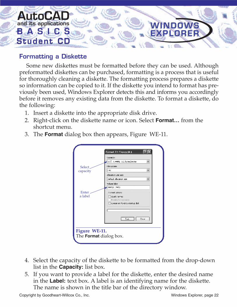
shortcut menu.3. The Format dialog box then appears, Figure WE-11.
4. Select the capacity of the diskette to be formatted from the drop-downlist in the Capacity: list box.
5. If you want to provide a label for the diskette, enter the desired namein the Label: text box. A label is an identifying name for the diskette.The name is shown in the title bar of the directory window.
Copyright by Goodheart-Willcox Co., Inc. Windows Explorer, page 22
and its applicationsAutoCADB A S I C SStudent CDStudent CD
WINDOWSWINDOWSEXPLOREREXPLORERWINDOWSEXPLORER
Selectcapacity
Entera label
Figure WE-11.The Format dialog box.

6. Pick the Start button to begin formatting the diskette.7. When the formatting is complete, pick OK.
Copying a DisketteThroughout this text you have been advised to always make a backup copy
of your AutoCAD drawings on portable storage media such as CD’s, 3.5″diskettes, or Zip disks. It is also a good idea to have a second backup of youroriginal backup. You can easily copy the contents of one diskette to anotherusing Windows Explorer. To copy a diskette, do the following:
1. Insert the source diskette in the drive you want to copy from. If yourcomputer has two drives, you caninsert the destination diskette inthe second drive. The destinationdiskette is called the copy todiskette.
2. Right-click the drive icon for thesource diskette in the folders pane.
3. Select Copy Disk… from the short-cut menu. The Copy Disk dialogbox appears, Figure WE-12.
Copyright by Goodheart-Willcox Co., Inc. Windows Explorer, page 23
and its applicationsAutoCADB A S I C SStudent CDStudent CD
WINDOWSWINDOWSEXPLOREREXPLORERWINDOWSEXPLORER
PROFESSIONALTIP Get in the habit of providing a volume label for each
diskette you format. Write the volume label name on the adhesive label before attaching it to the diskette.
Always use caution when formatting a diskette. Remember, in addition to preparing a new diskette, a format erases any existing data. Unless you are running a disk recovery utility program, you cannot recover information on a diskette that is accidentally formatted.
CAUTION
Figure WE-12.The Copy Disk dialog box.

4. Labels and icons representing the available drives are shown in theCopy Disk dialog box. Select the appropriate icons for the Copy from:and the Copy to: disks.
5. Pick the Start button. A Copy Disk alert asks you to insert the disketteyou want to copy from. Insert the proper diskette and pick OK. If youhave selected to use two different disk drives, you will be asked toinsert both the source and destination diskettes. If using a single diskdrive computer, you will have to switch diskettes when prompted.
6. At the next Copy Disk alert, insert the diskette you want to copy to andpick OK.
7. The contents of the source diskette are then copied to the destinationdiskette.
Protecting Your DiskettesDust, heat, cold, magnets, cigarette smoke, and coffee do great damage to
your diskettes. Placing your diskette on or near any other electrical or magneticdevice can quickly ruin your files. This includes your digitizer tablet! A ring-ing telephone can even be a dangerous enemy of the diskette because of itsmagnetic field. Beyond physical damage, you or someone else could writeover the files on a diskette, or put files on the wrong diskette, making themdifficult or impossible to find.
Copyright by Goodheart-Willcox Co., Inc. Windows Explorer, page 24
and its applicationsAutoCADB A S I C SStudent CDStudent CD
WINDOWSWINDOWSEXPLOREREXPLORERWINDOWSEXPLORER
The Copy Disk command not only copies, it formats! Therefore, there is no need to spend time formatting a diskette before making a copy. Be certain your destination diskette is blank or only has unneeded files on it.
CAUTION
PROFESSIONALTIP Single-density (360 KB) and double-density (720 KB)
diskettes can be read in Windows XP, but cannot be formatted or copied. If you receive an error while trying to copy a diskette you know to be good, make sure it is a high-density diskette (1.44 MB).
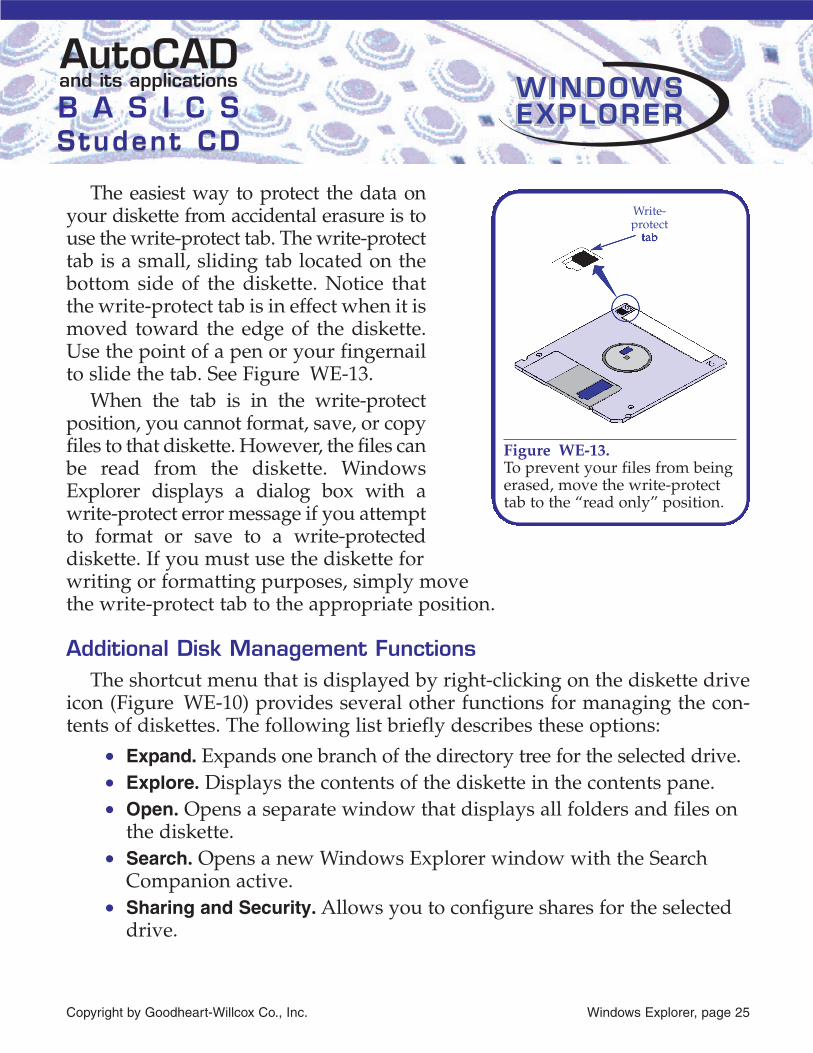
The easiest way to protect the data onyour diskette from accidental erasure is touse the write-protect tab. The write-protecttab is a small, sliding tab located on thebottom side of the diskette. Notice thatthe write-protect tab is in effect when it ismoved toward the edge of the diskette.Use the point of a pen or your fingernailto slide the tab. See Figure WE-13.
When the tab is in the write-protectposition, you cannot format, save, or copyfiles to that diskette. However, the files canbe read from the diskette. WindowsExplorer displays a dialog box with awrite-protect error message if you attemptto format or save to a write-protecteddiskette. If you must use the diskette forwriting or formatting purposes, simply move the write-protect tab to the appropriate position.
Additional Disk Management FunctionsThe shortcut menu that is displayed by right-clicking on the diskette drive
icon (Figure WE-10) provides several other functions for managing the con-tents of diskettes. The following list briefly describes these options:
• Expand. Expands one branch of the directory tree for the selected drive.• Explore. Displays the contents of the diskette in the contents pane.• Open. Opens a separate window that displays all folders and files on
the diskette.• Search. Opens a new Windows Explorer window with the Search
Companion active.• Sharing and Security. Allows you to configure shares for the selected
drive.
Copyright by Goodheart-Willcox Co., Inc. Windows Explorer, page 25
and its applicationsAutoCADB A S I C SStudent CDStudent CD
WINDOWSWINDOWSEXPLOREREXPLORERWINDOWSEXPLORER
Write-protect
b
Figure WE-13.To prevent your files from beingerased, move the write-protecttab to the “read only” position.

• Properties. Opens the Properties dialog box for the diskette. TheGeneral tab displays general information about the diskette and pro-vides a text box for naming the diskette. The Tools tab provides threetools that allow you to check the diskette for errors, defragment datastored on the diskette, and back up the diskette to a tape drive. TheHardware tab provides information about the various drives installedon the computer. The Sharing tab allows you to configure shares forthe drive. Check the Windows online help for additional informationon these tools.
Drag-and-Drop Operations with Windows ExplorerThe drag-and-drop functionality in Windows makes many common Windows
Explorer operations faster and easier. Drag-and-drop options are provided forcopying, moving, and deleting files and folders. When you drag any file or folderto a new location on the same disk drive, the items are moved to the new location.Dragging an item to a different disk drive creates a copy on the second disk drive.If the default operation is not what you need, you can drag the files or folders usingthe second mouse button (the right-click button).When you drop the items, a shortcut menuappears listing the available options. For exam-ple, the shortcut menu shown in Figure WE-14 isdisplayed when dragging an item to an alternatelocation on the same disk drive. Because movingthe file is the default operation, the Move Hereoption is shown in bold text. You can select fromthe other options or pick Cancel. To delete files orfolders, you can drag them to the Recycle Bin iconon either the desktop or in the folders pane.
Copyright by Goodheart-Willcox Co., Inc. Windows Explorer, page 26
and its applicationsAutoCADB A S I C SStudent CDStudent CD
WINDOWSWINDOWSEXPLOREREXPLORERWINDOWSEXPLORER
Many software applications place new options on the shortcut menu, so your menu may show additional options that are not listed here.
NOTEWhen AutoCAD is configured to display a screen menu, the commands appear in a separate screen.
Figure WE-14.The drag-and-dropshortcut menu providesadditional flexibility fordrag-and-drop operations.

The Windows Explorer can also be used to dynamically drag and drop fileicons into the AutoCAD drawing area. This powerful capability allows you toopen drawings, insert drawing files as blocks, insert text files as multiline text,and import PostScript and raster files. Drag-and-drop operations can also beused to load menu, linetype, shape, script, and slide files, as well as AutoLISPand ARX applications.
The following table lists the different kinds of drag-and-drop operationsthat can be used in AutoCAD. Also listed are the required file name exten-sions, the related AutoCAD commands, and the chapters in this text whereadditional command information can be found.
Additional files that can be used with drag-and-drop procedures are dis-cussed in AutoCAD and its Applications—Advanced. The following tablelists those files:
Copyright by Goodheart-Willcox Co., Inc. Windows Explorer, page 27
and its applicationsAutoCADB A S I C SStudent CDStudent CD
WINDOWSWINDOWSEXPLOREREXPLORERWINDOWSEXPLORER
Load a linetype file LIN LINETYPE Chapter 4Insert a text file TXT MTEXTLoad a shape font SHP COMPILEInsert a drawing file DWG INSERTOpen a drawing file DWG OPENPrint a drawing DWG PLOTLoad a slide file SLD Run a script file SCR SCRIPT Insert a DXF file DXF INSERT Windows Explorer ChapterOpen a DXF file DXF OPEN Windows Explorer ChapterLoad a DXB file DXB Windows Explorer Chapter
p
Operation File Related Related ChapterExtension Command
Load ADS and ARX applications EXE, ARX XLOADImport a PostScript image EPS, PS PSINLoad a menu file MNU MENUInsert an AutoLISP routine LSP LOAD
Operation File RelatedExtension Command
Dragging and Dropping a Text FileText, like other AutoCAD objects, can be saved to disk and inserted into
other drawing files. A text file created with a text editor outside of AutoCADcan also be inserted into a drawing using drag-and-drop if it is saved as a TXTfile. To drag a text file into AutoCAD, do the following:
1. Start both AutoCAD and Windows Explorer. Arrange the display windowsso both are visible.
2. In Windows Explorer, open the folder that contains the text file youwant to insert.
3. Select the text file icon, drag it into the AutoCAD drawing area, andthen release the mouse button. The text is inserted in the current textstyle and on the current layer.
The text file is inserted as a multiline text object, and appears with grips.The location of the text can be quickly changed with the grips.
External text files can be created with Notepad, WordPad, or your ownASCII text editor. Remember that the text file must have a TXT extension.Without this extension, a text file is not associated with an application andcannot be inserted.
Using Drag and Drop to Print a DrawingYou can plot a drawing by dragging the drawing file icon directly to the
appropriate printer icon. The drawing file icon you select is opened in thedrawing editor using the FILEOPEN command. This command allows you to
Copyright by Goodheart-Willcox Co., Inc. Windows Explorer, page 28
and its applicationsAutoCADB A S I C SStudent CDStudent CD
WINDOWSWINDOWSEXPLOREREXPLORERWINDOWSEXPLORER
PROFESSIONALTIP If you use the right mouse button when dragging a text file
into AutoCAD, a shortcut menu offers additional options. The Insert here option produces the same result as a regular drag-and-drop operation. Optionally, you can attach a hyperlink to an existing drawing object or cancel the operation. Using hyperlinks in AutoCAD is discussed in AutoCAD and its Applications—Advanced.

open a file without using a dialog box, regardless of the setting of the FILEDIAsystem variable. To use the FILEOPEN command, AutoCAD must first setSingle Document Interface mode active by setting the SDI system variable to1. Once the drawing appears in the drawing area, the Plot dialog box is dis-played. You can then modify the printing parameters as required and print thedrawing. After exiting the Plot dialog box, SDI is reset to its previous value.
To print a drawing on the system printer using drag and drop, do the following:
1. Launch AutoCAD and then launch Windows Explorer.2. Locate and select the folder containing the drawing you wish to print.
Right-click the folder icon and select Explore from the shortcut menu.Arrange and resize the windows as necessary so the contents pane ofeach window is visible.
3. In the original window, select and expand the Control Panel branch, andselect Printers and Faxes. See Figure WE-15.
Copyright by Goodheart-Willcox Co., Inc. Windows Explorer, page 29
and its applicationsAutoCADB A S I C SStudent CDStudent CD
WINDOWSWINDOWSEXPLOREREXPLORERWINDOWSEXPLORER
Drawingto be
printed Systemprinter
Figure WE-15.Use two Windows Explorer windows to print a drawing with the drag-and-dropmethod.

4. Select the file you wish to print in the second Windows Explorer win-dow and drag it to the desired printer icon in the original WindowsExplorer window. Release the mouse button.
5. The AutoCAD program window is moved to the front, the file isopened, and the Plot dialog box is displayed.
6. Make any necessary adjustments to the plotting parameters. Pick OK toprint the drawing.
The following is an alternative method of plotting a drawing file fromWindows Explorer:
1. Launch AutoCAD and then launch Windows Explorer.2. Locate the drawing you wish to print and right-click on it. Select Print
from the shortcut menu.
Dragging and Dropping Drawing Files into AutoCADOne or more drawing files can be easily opened in AutoCAD using a drag-
and-drop procedure. It is important to remember when you want to open afile, you need to drag it to the title bar of the AutoCAD program window.
1. Start both AutoCAD and Windows Explorer.2. Arrange the display so both windows are visible.3. Select any number of drawing files in Windows Explorer.
Copyright by Goodheart-Willcox Co., Inc. Windows Explorer, page 30
and its applicationsAutoCADB A S I C SStudent CDStudent CD
WINDOWSWINDOWSEXPLOREREXPLORERWINDOWSEXPLORER
PROFESSIONALTIP You can place a printer icon on the Windows desktop and
avoid having to open the My Computer and Printers windows. Simply create a Windows shortcut by pressing the [Ctrl] key, then picking and dragging the printer icon to a location on the desktop. The label below this icon will change to “Shortcut to…”. To change the label, pick the name to highlight it and then pick it again to edit. Type a new name, then press [Enter]. Now when you need to print a document, just drag the file name from Windows Explorer and drop it on the new printer icon.

4. Drag the selected file icons to the title bar of the AutoCAD programwindow.
5. Each drawing is then opened in a separate drawing window.
Drag and drop can also be used to insert any drawing into the current draw-ing session. This method is very similar to the INSERT command discussed inChapter 22. Like INSERT, the drawing you drag and drop becomes a block.Therefore, be sure to explode it after insertion, if necessary. To insert a drawing,drag it into the drawing area of the drawing you want to insert it into.
Drawings can only be inserted one at a time. Using the right mouse buttonwhen dragging files into the drawing area displays a shortcut menu with thefollowing options:
• Insert here. Inserts the drawing the same as a regular drag-and-dropoperation.
• Open. Opens the drawing in a new drawing window.• Create Xref. Attaches an external reference to the selected drawing
using the drop point as the insertion location and default scale androtation.
• Create Hyperlink here. Creates a hyperlink to the drawing attached toa selected object.
• Cancel. Stops the drag-and-drop operation.
Recovering a Damaged DrawingA damaged drawing file is one that has been corrupted and cannot be
loaded into the AutoCAD drawing editor with the OPEN command.Drawings can be corrupted in the following ways:
Copyright by Goodheart-Willcox Co., Inc. Windows Explorer, page 31
and its applicationsAutoCADB A S I C SStudent CDStudent CD
WINDOWSWINDOWSEXPLOREREXPLORERWINDOWSEXPLORER
This chapter has introduced you to only some of the features within Windows Explorer. Become familiar with all the functions offered by this useful tool. By making Windows Explorer an integral part of your daily work, you can greatly increase your productivity.
NOTEWhen AutoCAD is configured to display a screen menu, the commands appear in a separate screen.

• A bad or corrupted diskette.• Running out of disk space during a drawing session.• Power failures.• Hardware or software problems.
A valuable resource for recovering lost or damaged drawing data is the back-up file. By default, AutoCAD creates a BAK file when you save a drawing—soa BAK file stores the drawing prior to your most recent save operation. A BAKfile is also a drawing file, but it uses a different file extension.
AutoCAD does not allow you to open BAK files directly. To open a BAKfile, it must be renamed to end in a .dwg file extension. Note WindowsExplorer must be configured to display file extensions to be able to changethem.
When a BAK file does not provide the best solution,AutoCAD provides a method for recovering most dam-aged files. You can type RECOVER at the Command:prompt, or select Recover… from the Drawing Utilitiescascading menu in the File pull-down menu. This dis-plays the Select File dialog box. Select the proper folderand file and AutoCAD attempts to recover the damageddrawing. If it is successful, the file is loaded into thedrawing editor, and it can be worked on normally. If youdo not save the file before exiting AutoCAD, the recov-ered drawing is lost.
There is also an automatic saving feature in AutoCAD that creates a tempo-rary backup file during a drawing session. This file can be a valuable backupif you find your drawing is corrupted as a result of an improper terminationor system crash. By default, AutoCAD names the automatically saved fileDrawingName_n_n_nnnn.sv$ and saves it in the C:\Documents andSettings\User\Local Settings\Temp folder. If you need to use this file, you mustrename it as a DWG file in Windows Explorer.
Copyright by Goodheart-Willcox Co., Inc. Windows Explorer, page 32
and its applicationsAutoCADB A S I C SStudent CDStudent CD
WINDOWSWINDOWSEXPLOREREXPLORERWINDOWSEXPLORER
RECOVER
File� Drawing Utilities� Recover...

Using the AUDIT CommandYou can perform a diagnostic check on your drawing files with the AUDIT
command. This checks for and corrects errors. You have the option of fixingerrors or leaving them.
Command: AUDIT↵Fix any errors detected? [Yes/No] <N> ↵1 Blocks audited55 Blocks auditedPass 1 539 objects auditedPass 2 539 objects auditedPass 3 5500 objects auditedTotal errors found 0 fixed 0Command:
If you answer no, as in the above example, all errors are listed for your ref-erence, but they are not fixed. To fix errors in the transferred drawing, type Yat the Fix any errors detected? prompt.
AutoCAD displays the errors and notifies you they are fixed like this:3 Blocks auditedPass 1 29 objects auditedPass 2 14 objects auditedTotal errors found 2 fixed 2
If the system variable AUDITCTL is set to 1 (on), AutoCAD automaticallycreates an audit report that lists the corrections made. This report is given thesame name as the drawing, but has an ADT file extension. The file is placed inthe same directory as the drawing. This is an ASCII text file (AmericanStandard Code for Information Interchange). You can open this file and readthe information using any ASCII text editor, such as Windows Notepad orWordPad.
Copyright by Goodheart-Willcox Co., Inc. Windows Explorer, page 33
and its applicationsAutoCADB A S I C SStudent CDStudent CD
WINDOWSWINDOWSEXPLOREREXPLORERWINDOWSEXPLORER
AUDIT
File� Drawing Utilities� Audit

Listing the Audit ReportIt is not necessary to leave AutoCAD to display the audit report. Simply
pick Programs, Accessories, and then Notepad from the Start menu.To list the audit report, first select Open… from the File menu. Then, select
the audit file. Pick OK and the contents of the file are displayed on the screen.After reviewing the file, you can exit Notepad.
Understanding AutoCAD’s Temporary FilesAutoCAD maintains several temporary files while you are working on a
drawing. You might consider these as “worksheets” AutoCAD opens, muchlike the notes, references, sketches, and calculations you may have scatteredaround your desk. These files are created automatically to store portions of theAutoCAD program not currently in use and information related to the currentdrawing file. These files are critical to AutoCAD’s operation, and must bemaintained and safeguarded properly.
Program Swap FilesAutoCAD uses a virtual memory system. Virtual memory is a combination
of memory and hard disk space. The main program file for AutoCAD isnamed acad.exe. It is a large file—over 6.6 MB. If there is not enough room inyour computer’s physical memory (RAM) to store the program, AutoCADcreates pages of the program in free space on your hard disk drive.
A virtual memory system keeps only the part of the program that is cur-rently being used in physical memory. If additional portions of the programare needed, AutoCAD creates a page on the hard disk and writes the least-used portion of the program to that page. The new portion of the program thatis requested is written to physical memory. Thus, AutoCAD creates a pagingsystem using virtual memory. The least-used pages are written to a pagecalled a swap file, and are held there until needed again.
When required, AutoCAD’s paging system automatically creates andmaintains a swap file. These files are critical to AutoCAD, and must never bedeleted while you are in a drawing session. Should you experience an impropertermination of AutoCAD, and the drawing file is not saved properly, these
Copyright by Goodheart-Willcox Co., Inc. Windows Explorer, page 34
and its applicationsAutoCADB A S I C SStudent CDStudent CD
WINDOWSWINDOWSEXPLOREREXPLORERWINDOWSEXPLORER

swap files may be left open. In that case, the files are no longer of use and canbe deleted, but only after you have exited AutoCAD.
Temporary FilesThe second piece of AutoCAD’s virtual memory system is called the pager.
The pager is similar to the swap file system, but creates temporary storagespace for drawing file information. The entire contents of a small drawingmay fit into your computer’s physical memory, but as the drawing grows larger,portions of it must be temporarily removed. AutoCAD creates a page file forthe least-used portion of your drawing, and opens the physical memory fornew drawing data. When the drawing data contained in the page file is need-ed, it is paged back into memory. These temporary files are given the fileextension of AC$. These are vital files and must never be deleted while work-ing in AutoCAD.
If AutoCAD should terminate improperly, these page files are left open inthe temporary files directory—usually C:\Documents and Settings\User\LocalSettings\Temp. If AutoCAD is no longer running, the AC$ files left behind areno longer of any use, and can be deleted. Always delete these files withWindows Explorer, and never while you are working in AutoCAD.
Creating a Workspace for Temporary FilesThe default workspace for AutoCAD’s temporary files is C:\Documents and
Settings\User\Local Settings\Temp. You can create a folder on your hard driveand tell AutoCAD to always use that folder for storage of temporary files. Usethe following procedure to allocate space for these files:
1. Pick Options… in the Tools pull-down menu or right-click and selectOptions… from the shortcut menu. This displays the Options dialog box.
2. Pick the Files tab.3. Pick the + symbol to the left of Temporary Drawing File Location. The cur-
rent location is displayed. See Figure WE-16.4. Pick the current directory (folders) path to select it.5. Pick the Browse… button to display the Browse for Folder dialog box.6. Find the folder you want to use for temporary files and select it. Pick
OK to exit.
Copyright by Goodheart-Willcox Co., Inc. Windows Explorer, page 35
and its applicationsAutoCADB A S I C SStudent CDStudent CD
WINDOWSWINDOWSEXPLOREREXPLORERWINDOWSEXPLORER

Importing and Exporting FilesAutoCAD provides you with the ability to work with files other than DWG
files. You can import external data into a drawing, or export the current draw-ing to files that can be used in other programs for rendering, animation, desk-top publishing, presentations, stereolithography, and solid modeling. Thissection provides a brief overview of AutoCAD’s capabilities in importing andexporting a variety of different files.
Copyright by Goodheart-Willcox Co., Inc. Windows Explorer, page 36
and its applicationsAutoCADB A S I C SStudent CDStudent CD
WINDOWSWINDOWSEXPLOREREXPLORERWINDOWSEXPLORER
Pick toselect a
differentfolder
Location oftemporary
files
Figure WE-16.The location of temporary drawing files can be specified in the Optionsdialog box.
After you complete step 3, you can type in a new location if you know the exact path (rather than “browse” for it). Be sure to specify the drive letter and complete path. For example, if you created a folder on the C: drive in the \AutoCAD 2005 folder named Tempfile, the proper path to type is C:\AutoCAD 2005\Tempfile.
NOTEWhen AutoCAD is configured to display a screen menu, the commands appear in a separate screen.

DXF FilesThe DXF file format is commonly used for sharing drawing files with CAD
applications other than AutoCAD. DXF is an acronym for drawing interchangeformat. A DXF file is simply an ASCII text file that defines the objects and set-tings within a drawing. You can save an entire drawing or just selected objectsas a DXF file using either the SAVEAS or WBLOCK command.
When using SAVEAS, select the desired DXF versionfrom the Files of type: list. You can save the DXF file tobe compatible with AutoCAD 2004, AutoCAD 2000/LT2000, or AutoCAD R12/LT2. See Figure WE-17. Fromthe Save Drawing As dialog box, pick Options… from theTools menu to access the DXF Options tab of the SaveasOptions dialog box. The available options are as follows:
• ASCII. Writes the DXF file in a standard ASCII text format.
Copyright by Goodheart-Willcox Co., Inc. Windows Explorer, page 37
and its applicationsAutoCADB A S I C SStudent CDStudent CD
WINDOWSWINDOWSEXPLOREREXPLORERWINDOWSEXPLORER
SAVEAS
File� Save As...
Use Toolsmenu to
change DXFoptions
Select type ofDXF file
Figure WE-17.The Save Drawing As dialog box allows you to save a drawing as one of threedifferent forms of DXF file. In addition to Windows Explorer, several otherprograms are included with the Windows operating system. The particularprograms available depend on your Windows installation. Some typical programs are shown here.

• BINARY. Writes the DXF file using a binary file format. This optioncan reduce the size of the translated file by 25% or more.
• Select objects. Allows selection of specific drawing objects to besaved to the DXF file.
• Save thumbnail preview image. Saves a preview image with the file.• Decimal places of accuracy (0 to 16). Specifies the decimal places of
precision for ASCII format DXF files.
To write a DXF file using the WBLOCK command,specify a file name with a .dxf extension in the FileName: text box in the Write Block dialog box. TheWBLOCK command automatically creates an AutoCAD2004 format DXF file.
Existing DXF files can be opened directly with theOPEN command, or their contents can be inserted intothe current drawing using the INSERT command. Toaccess DXF files in the file selection dialog boxes dis-played by these commands, specify DXF (*.dxf) in theFiles of type: list.
DXF applicationsThere are several applications for which you will want to convert an
AutoCAD file to DXF format. The most common application is sharingdrawings with CAM systems or other CAD systems. Numerical control(NC) programs also use DXF files. The file is used to translate the shape andfeatures of a machine part to code that can be used for lathes, millingmachines, and drill presses. In addition, desktop publishing programs useDXF files to translate drawings into images that can be inserted into a pagelayout. Also, programs that perform stress analysis and calculations oftenrely on DXF drawings.
Importing a Scanned FileScanning is the process of creating an electronic file from a hard copy.
Scanners reflect light off the hard copy and translate this data into an electronicfile. Many scanning programs create a DXB (drawing interchange binary) fileafter scanning an existing paper drawing with a camera or plotter-mountedCopyright by Goodheart-Willcox Co., Inc. Windows Explorer, page 38
and its applicationsAutoCADB A S I C SStudent CDStudent CD
WINDOWSWINDOWSEXPLOREREXPLORERWINDOWSEXPLORER
WBLOCK

scanner. The file created is in binary code. The DXBIN command converts thiscode into drawing data. This drawing data becomes an AutoCAD drawing filewith a .dwg extension.
To import a DXB file, pick Drawing ExchangeBinary… from the Insert pull-down menu, or typeDXBIN at the Command: prompt. The Select DXB Filedialog box appears. Select the scanned file and pick theOpen button. You can then edit the drawing using typi-cal AutoCAD commands. After editing the drawing, itcan be saved as a drawing file.
Autodesk VIZ and 3D Studio FilesAutodesk VIZ and 3ds max are programs that allow you to design, render,
and animate 3D models. Both of these applications can use the 3D Studio(3DS) file format. You can export or import 3D Studio files with AutoCAD.
To export a 3D Studio file, type 3DSOUT at theCommand: prompt. Next, you are prompted to selectobjects. Select all the objects you wish to export andpress [Enter]. The 3D Studio Output File dialog box isdisplayed. Enter the file name in the File name: textbox. Press [Enter] or pick Save when you are finished.Exporting a 3D Studio file can also be executed usingthe EXPORT command or selecting Export… from theFile pull-down menu and then picking the 3D Studio(*.3ds) file type in the Export Data dialog box.
You can import an existing 3D Studio file intoAutoCAD by selecting 3D Studio… from the Insertpull-down menu. The 3D Studio File Import dialog boxis displayed. Select the appropriate 3DS file from thelist and press [Enter]. You can also import a 3D Studiofile by typing 3DSIN at the Command: prompt.
Copyright by Goodheart-Willcox Co., Inc. Windows Explorer, page 39
and its applicationsAutoCADB A S I C SStudent CDStudent CD
WINDOWSWINDOWSEXPLOREREXPLORERWINDOWSEXPLORER
3DSIN
Insert� 3D Studio...
3DSOUT
File� Export...
DXBIN
Insert� Drawing
ExchangeBinary...

Solid Model FilesA solid model is a computer representation that contains information of the
entire volume of a 3D object. The solid model may include information aboutmaterial strength, flexibility, surface finish, mass, and translucency. Solids arecreated in AutoCAD with commands found in the Solids cascading menu ofthe Draw pull-down menu. This procedure is discussed in detail in AutoCADand its Applications—Advanced.
A solid model is frequently used with analyzing andtesting software and in part manufacturing. TheACISOUT command converts AutoCAD drawings intoa file format that is useful for these purposes. To acti-vate the ACISOUT command, choose Export… from theFile pull-down menu. Pick ACIS (*.sat) in the Files oftype: drop-down list of the Export Data dialog box.When you pick OK, you are prompted to select objects.Use any of the standard selection methods to choosethe solid objects, then press [Enter]. If ACISOUT is typedat the Command: prompt, the Create ACIS File dialogbox is displayed instead of the Export Data dialog box.Notice that SAT file is the default setting. Do notchange this. Type the file name in the File name: textbox and press [Enter] or pick Save. The SAT file isstored in ASCII format.
Solid model data stored in the SAT file can be readback into AutoCAD using the ACISIN command. Whenyou enter this command, the Select ACIS File dialogbox is displayed. Pick the file from the list, then pickOpen or press [Enter]. You can also activate the ACISINcommand by picking ACIS File… in the Insert pull-down menu.
Copyright by Goodheart-Willcox Co., Inc. Windows Explorer, page 40
and its applicationsAutoCADB A S I C SStudent CDStudent CD
WINDOWSWINDOWSEXPLOREREXPLORERWINDOWSEXPLORER
ACISOUT
File� Export...
ACISIN
File� Export...
Stereolithography FilesStereolithography is a technology that can create a three-dimensional plas-
tic prototype model using a computer-generated solid model, a laser, and avat of liquid polymer. This technology is also referred to as rapid prototypingbecause a prototype 3D model can be designed and formed in a short amountof time, without using standard manufacturing processes. Most software usedto create a stereolithograph can read an STL file. AutoCAD can export a draw-ing file to the STL format, but cannot import an STL file.
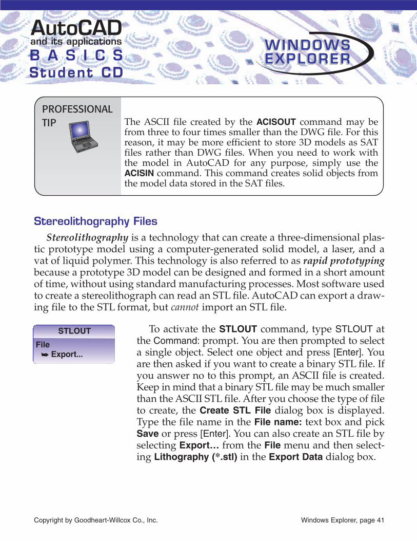
To activate the STLOUT command, type STLOUT atthe Command: prompt. You are then prompted to selecta single object. Select one object and press [Enter]. Youare then asked if you want to create a binary STL file. Ifyou answer no to this prompt, an ASCII file is created.Keep in mind that a binary STL file may be much smallerthan the ASCII STL file. After you choose the type of fileto create, the Create STL File dialog box is displayed.Type the file name in the File name: text box and pickSave or press [Enter]. You can also create an STL file byselecting Export… from the File menu and then select-ing Lithography (*.stl) in the Export Data dialog box.
Copyright by Goodheart-Willcox Co., Inc. Windows Explorer, page 41
and its applicationsAutoCADB A S I C SStudent CDStudent CD
WINDOWSWINDOWSEXPLOREREXPLORERWINDOWSEXPLORER
STLOUT
File� Export...
PROFESSIONALTIP The ASCII file created by the ACISOUT command may be
from three to four times smaller than the DWG file. For this reason, it may be more efficient to store 3D models as SAT files rather than DWG files. When you need to work with the model in AutoCAD for any purpose, simply use the ACISIN command. This command creates solid objects from the model data stored in the SAT files.

Postscript FilesPostScript is a copyrighted page description lan-
guage developed by Adobe Systems. This language iswidely used in the desktop publishing industry.AutoCAD drawing files can be exported to the EPSPostScript file format by typing PSOUT at theCommand: prompt. The Create PostScript File dialogbox is displayed. You can also pick Export… from theFile pull-down menu to display the Export Data dialogbox. Then, pick Encapsulated PS (*.eps) in the file typedrop-down list. Type the file name in the File name:text box and pick Save or press [Enter].
There are additional options for exporting PostScriptfiles. To set these options, select Options… from theTools menu in the Create PostScript File dialog box orExport Data dialog box. This accesses the PostScriptOut Options dialog box, which allows you to fine-tunethe content and appearance of the exported EPS file.The use of PostScript files is discussed in detail inAutoCAD and its Applications—Advanced.
Additional FilesThree additional files are listed in the Export Data dialog box and are
defined here:
• Metafile (.wmf). This is a Windows file that contains vector information,therefore it can be scaled while retaining its resolution. See AutoCADand its Applications—Advanced for a detailed discussion of metafiles.
• DXX Extract (.dxx). A block’s attribute information can be extracted tothis file. This file is created using the ATTEXT command, which is dis-cussed in Chapter 23.
• Bitmap (.bmp). A bitmap is a digital image composed of bits, or pixels.A bitmap is also referred to as a raster image. Unlike the metafile for-mat, a bitmap contains no vector information. Bitmaps are discussedin AutoCAD and its Applications—Advanced.
Copyright by Goodheart-Willcox Co., Inc. Windows Explorer, page 42
and its applicationsAutoCADB A S I C SStudent CDStudent CD
WINDOWSWINDOWSEXPLOREREXPLORERWINDOWSEXPLORER
PSOUT
File� Export...