Lesson 10 Design Tables and Equations - Faculty...
42
301 Lesson 10 Design Tables and Equations Upon successful completion of this lesson, you will be able to: ■ Link dimension values together to capture design intent. ■ Create Equations. ■ Automatically create design tables. ■ Use existing design tables to create families of parts. ■ Make detail drawings using more advanced types of drawing views.
Transcript of Lesson 10 Design Tables and Equations - Faculty...

SolidWorks 2006 Training Manual
301
Lesson 10Design Tables and Equations
Upon successful completion of this lesson, you will be able to:
� Link dimension values together to capture design intent.
� Create Equations.
� Automatically create design tables.
� Use existing design tables to create families of parts.
� Make detail drawings using more advanced types of drawing views.

Lesson 10 SolidWorks 2006 Training ManualDesign Tables and Equations
302

SolidWorks 2006 Training Manual Lesson 10Design Tables and Equations
Design Tables 303
Design Tables Design Tables are the best way to create configurations of parts. They are used to control dimension values for families of parts, and suppression states of features. Design tables can be used to create a family of parts from a single part design. Since the SolidWorks software is an OLE/2 application, an Excel spreadsheet is used to lay out the design table so it can be imported into the SolidWorks document.
Key Topics The key topics covered in this lesson are shown in the following list.
� Link Values
Link values are used to set two or more dimensions equal.
� Equations
Equations can be used to create algebraic relationships between dimensions using mathematical operators and functions.
� Auto-create a Design Table
Design tables can be automatically created and edited after they are inserted. Design tables can be set so that you cannot change the model if those changes would update the design table.
� Making changes
Changes can be made to the existing design table by editing the table to add configurations, dimensions or features.
� Bi-directional Changes
Dimensions that appear in the design table are driven by it. Changes made to the dimensions in the model force the corresponding change in the design table.
� Inserting Blank Design Tables
Blank design tables are useful for many purposes including exploded views and multiple positions of a component in an assembly.
� Drawings with Configurations
Drawings with parts that have configurations provide many options for display. Any available configuration can be displayed in a model view.
Lesson 10 SolidWorks 2006 Training ManualDesign Tables and Equations
304 Link Values
1 Open Socket.
The Socket part (shown here with Show Feature
Dimensions and Show Dimensions
Names on) contains two cut features that represent the overlapping hexagon cuts. They retain their original names.
2 Change value.
Double-click the sketch of the 6 Point feature and double-click the 0.5” dimension. Add 1/32” to the nominal value as shown. Rebuild the model.
Link Values Link Values can be used to set a series of dimensions equal by assigning them the same name. Changing the value of any of the linked dimensions changes all of them. The linking can be removed using Unlink Value. This option is superior to equations for setting several values equal to each other.
In this example there are two linear dimensions: one in each of the hexagon shaped cuts. Link values will be used to tie them together.
Where to Find It � From the Dimension Modify dialog, choose Link Value.� Right-click one or more dimensions and select Link Values.
Note The dimensions being linked together must be of the same type. Link angular dimensions to other angular dimensions and so forth.
3 Access link values.
Double-click the same dimension as if to change the value. Using the dropdown menu, select Link Value.
4 Name the link
value.
In the Shared
Values dialog, type the name AcrossFlats and click OK.

SolidWorks 2006 Training Manual Lesson 10Design Tables and Equations
Equations 305
5 Link Value added.
The link value is added and is used as the dimension name. A prefix symbol is also added to identify this dimension as being linked.
Rebuild the model.
6 Equation folder.
The link value is listed under the Equations folder in the FeatureManager.
7 Add link value.
Double-click the sketch of the 12 Point feature and double-click the 0.5” dimension. Select the link value AcrossFlats from the dropdown. The value of the existing link value is assigned to this dimension. Rebuild the model.
Note A link value will remain attached to a dimension unless it is removed using right-click Unlink Value. Changing the value of any linked dimension changes all linked dimensions.
Equations Many times you will need to establish a relationship between parameters that cannot be achieved using geometric relations or modeling techniques.
For example, you can use equations to establish mathematical relations between dimensions in the model. This is what we will do next.
This equation will establish a relationship between the diameter of the cylinder and the distance across the flats of the hex. As the distance across the flats increases, so will the diameter.
Note Simple equality statements within a part can be created more easily with Link Values than equations.

Lesson 10 SolidWorks 2006 Training ManualDesign Tables and Equations
306 Equations
Preparation for Equations
Although you can begin writing equations and applying them to the model with little or no preparation, it is a much better practice to make a small investment in time up front to achieve added benefit later on. You should consider the following:
� Renaming the dimensions
Dimensions are created by the system with somewhat cryptic default names. To make it easier for others to interpret the equations and understand what exactly is being controlled by them, you should rename the dimensions giving them more logical and easily understood names. Right-click a dimension and choose Properties to rename it.
Note When equations are used in an assembly, the full name uses the form: Name@FeatureName@PartName.
� Dependent versus independent
The SolidWorks software uses equations of the form Dependent =
Independent. This means that in the equation A = B, the system solves for A when given B. You can edit B directly and change it. Once the equation is written and applied, you cannot directly change A. Before you start writing equations, you need to decide which parameter will drive the equation (the independent one) and which will be driven by the equation (the dependent one).
� Which dimension drives the design?
In this example, we will control the diameter of the cylinder based on the distance across the flats of the hex. This means the flat distance is the driving or independent parameter and the diameter is the driven or dependent one. The size of the hex drives the design.
Functions The functions displayed as buttons on the Add Equation dialog box include basic operators, trig functions and many more.
Equation form The equation required in this example uses the distance across the flats of the hex as the driving dimension. This forces changes in the cylinder diameter, a feature that precedes it. The form is:
Driven Dimension = Driving Dimension + Constant
where:
Driven Dimension = CylinderDiameter@Sketch1
Driving Dimension = AcrossFlats@Sketch2
Constant = 0.25
Introducing:
Equations
The Equations dialog can be used to add, edit, delete and configure equations.
SolidWorks 2006 Training Manual Lesson 10Design Tables and Equations
Equations 307
Where to Find It � Click Equations on the Tools toolbar.� Or from the Tools menu, click Equations.� Or right-click the Equations folder and choose an option.� Or from the Dimension Modify dialog, choose Add Equation.
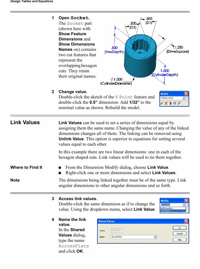
8 Add Equation.
Double-click the Cylinder feature and the diameter dimension (1”). In the dialog, choose Add Equation from the dropdown list.
9 Dimension added.
The dimension is added to the new equation on the left side of the equals sign.
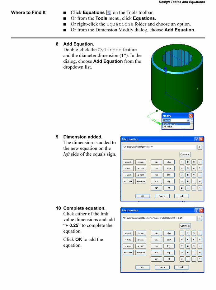
10 Complete equation.
Click either of the link value dimensions and add “+ 0.25” to complete the equation.
Click OK to add the equation.
Lesson 10 SolidWorks 2006 Training ManualDesign Tables and Equations
308 Equations
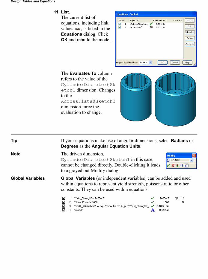
11 List.
The current list of equations, including link values , is listed in the Equations dialog. Click OK and rebuild the model.
The Evaluates To column refers to the value of the CylinderDiameter@Sketch1 dimension. Changes to the AcrossFlats@Sketch2 dimension force the evaluation to change.
Tip If your equations make use of angular dimensions, select Radians or Degrees as the Angular Equation Units.
Note The driven dimension, CylinderDiameter@Sketch1 in this case, cannot be changed directly. Double-clicking it leads to a grayed out Modify dialog.
Global Variables Global Variables (or independent variables) can be added and used within equations to represent yield strength, poissons ratio or other constants. They can be used within equations.

SolidWorks 2006 Training Manual Lesson 10Design Tables and Equations
Design Tables 309
A Few Final Words About Equations
Equations are solved in the order in which they are listed. If you change a dimension and discover that it takes two rebuilds to update all of the part’s geometry, this may indicate that your equations are in the wrong order. Edit the equations and use the list to reorder them. Consider this example:
Given three equations: A=B, C=D, and D=B/2, consider what happens if you change the value of B. First, the system will compute a new value for A. When it evaluates the second equation, nothing is changed. When the third equation is evaluated, the changed value of B yields a new value for D. However, it isn’t until the second rebuild that this new value for D gets used to compute a new value for C. Reordering the equations thus: A=B, D=B/2, and C=D solves the problem.
Design Tables Design Tables are the best way to create configurations of parts. They are used to control dimension values for families of parts and suppression states of features.
Auto-create a Design Table
The easiest way to create a Design Table in a part is to Auto-create it using existing configurations, dimensions and features. The existing information is automatically formatted into an Excel spreadsheet and updates automatically, by default bi-directionally.
Introducing: Insert
Design Table
When you insert a design table, the SolidWorks window switches to Excel. That is, the toolbars become Excel toolbars instead of SolidWorks toolbars while the table is active.
There can only be one design table in each part. It is stored within the part document unless a linked design table is used.
Where to Find It � Click Insert, Design Table....
� Or, click Design Table on the Tools toolbar.
FeatureManager
Design Tree
When a design table is added to a part or assembly, this symbol
appears in the FeatureManager design tree.

Lesson 10 SolidWorks 2006 Training ManualDesign Tables and Equations
310 Design Tables
12 Insert a new design table.
Click Insert, Design Table.... For the Source select Auto-create to automate the creation of the design table.
� Source determines where information comes from. Blank creates a new, blank, design table. Dimensions and features can be added to the design table by double-clicking them. Auto-
create generates a design table from existing configurations, dimensions and features. From
file imports an existing Microsoft Excel spreadsheet to use as the design table. Click Browse to locate the table. You can also select the Link to file check box, which links the spreadsheet to the model.
� Edit Control controls the ability to make bi-directional changes. Selecting Allow model
edits to update the design table means that changes can be made outside the table and it will still be updated.
� Options determines how new information in treated by the design table. If it is set to bi-directional, new features, configurations and dimensions changes force updates in the design table.
Tip Dimensions that are driven by the design table appear in a different color scheme. You can change the color of dimensions that are controlled by the design table to make them easier to identify.
Click Tools, Options, System Options, Colors.
Select the option Dimensions, Controlled by Design Table and edit the color.

SolidWorks 2006 Training Manual Lesson 10Design Tables and Equations
Design Tables 311
13 Dimensions to add.
The Auto-create option generates a list of the dimensions in the part that can be added to the design table.
Press Ctrl and select these four dimensions:
CylinderDepth@Cylinder
AcrossFlats@Sketch2
HexDepth@6 Point
DriveSquare@Sketch4
Tip The dimensions that will be used in the table should be renamed to more meaningful names than their default ones.
14 Design table.
The selected dimensions are added to the design table with their associated values. Note that the long dimension names are automatically rotated vertical.
Excel Formatting The cells in the spreadsheet appear with the standard formatting but they can be changed at any time. Take advantage of the power of Excel to make the design table easier to read and use. You can:
� Change cell colors and borders� Change text color, orientation and font� Define functions between cells
All of these changes can make the design table more useful or just more readable.

Lesson 10 SolidWorks 2006 Training ManualDesign Tables and Equations
312 Design Tables
Anatomy of a Design Table
The design table contains rows and columns of information that are set into predefined cells of the Excel spreadsheet.
Properties Used in
the Design Table
The Properties that live in Row 2 of the design table can be used to set a dimension value, suppress or unsuppress a feature or add a comment. The chart below summarizes the available properties and valid cell values.
Title
Properties
Configuration Cell Values
Property Header Example Cell Value Description
Dimension D3@Sketch2 Number The value should be appropriate for the dimension.
Tolerance $TOLERANCE@D1@Sketch1
Tolerance type (text); Maximum Variation (number); Minimum Variation (number)
The format sets the type and values separated by semi-colons (;) for a single dimension.
State $STATE@Fillet5 S, U, Suppressed, Unsuppressed, or blank.Blank = Unsuppressed
Sets the state of a feature to be suppressed or unsuppressed.
Color $COLOR 32-bit integer number. Color value is derived from palette color or material.
Parent $PARENT Text Parent configuration name.
Comment $COMMENT Text Alpha-numeric.
User Notes* $USER_NOTES Text Alpha-numeric.* Can be used as a column or row header.
Property $prp@prop_name Text A custom property name prop_name created in the table or through File,
Properties.

SolidWorks 2006 Training Manual Lesson 10Design Tables and Equations
Design Tables 313
Adding New Headers
New property headers, feature or dimension based, can be added to the table by double-clicking. For a feature, double-click it in the FeatureManager or on the screen. The result is a $STATE property (see Properties Used in the Design Table on page 312). For a dimension, double-click it in the graphics area.
Note The next available cell in row 2 must be selected before double-clicking.
15 Add feature.
Double-click the 12 Point feature on the FeatureManager. It is added to the design table with the prefix $STATE@. The current state, UNSUPPRESSED, is also added.
Change the value UNSUPPRESSED to the abbreviation U.
Note The UNSUPPRESSED cells can be abbreviated as U. SUPPRESSED cells can be abbreviated as S. A lowercase u or s would be converted to uppercase.
Adding Configurations to the Table
Once the design table has been established, configurations and associated cell values can be added by typing. In this example, a new configuration name will be created and copied to generate more.
16 Add a new configuration.
Replace in the Default configuration name with 0.5 Short 12 in the cell A3. Close the table.
17 Delete configuration.
Exit the design table confirming the creation of a new configuration.
In the Configuration Manager, make the new configuration active and delete Default.

Lesson 10 SolidWorks 2006 Training ManualDesign Tables and Equations
314 Design Tables
18 Add more configurations.
Right-click the Design Table
feature and select
Edit Table. Add more configurations quickly by selecting cells A3-F3 and dragging the lower right corner of the selection box down to row 5. Modify some of the cells as shown.
19 Configurations added.
Close the design table to add the new configurations. A message appears indicating the names of new configurations that have been added.
Tip If configurations are missing from the list, there is a problem in the design table. Often the problem is an inappropriate cell value. If so, a message will appear, stating that a value is invalid.
20 Resulting configurations.
Switch to the Configuration Manager and double-click each configuration to make it active.
Only one configuration can be active at any time.
21 Add configurations and
comments.
Using copy and paste with editing, create as many additional configurations, and formatting as time permits.
0.5 Short 12 0.625 Short 12 0.75 Short 12

SolidWorks 2006 Training Manual Lesson 10Design Tables and Equations
Existing Design Tables 315
22 Configurations created.
If all configurations are created, there are 6 configurations. For each size there is a 6 and 12 point version.
Existing Design Tables
Another way to add a design table is to create the table in Excel and insert it into the part. Here are some tips when using this method:
� Rename dimensions
As previously mentioned, the default dimension names are generally non-descriptive. Rename them by editing the Properties of the dimension and modifying the Name field.
� Copy dimension and feature names
The design table is very fussy about the spelling and case of dimension and feature names. Use copy and paste to extract the Full name of the dimension from the Properties dialog and add it to the cell. For features, also use the Properties dialog.
� Fill in all cells
All the cells within the rows and columns that you create must have the appropriate type of data in them.
1 Open the part named Part_DT.
The part, Part_DT, will be used to demonstrate the power of existing design tables.
The part has both revolved and extruded features. Note that multiple features are used where one revolved could be used. This allows the individual features to be suppressed.
2 Key dimensions.
Using properties, some key dimensions have been changed from their default names to something more descriptive. Only those that appear in the design table need to be changed.

Lesson 10 SolidWorks 2006 Training ManualDesign Tables and Equations
316 Existing Design Tables
If the default names are used, comments can be added to the design table to describe the dimension further.
Tip When it comes time to copy the dimension names into the spreadsheet, it will be easier to select the names if they do not have embedded spaces.
Inserting the Design Table
After creating the design table, it has to be inserted into the appropriate SolidWorks part. To do this, use the following procedure:
3 Insert the design table into the part.
Click Design Table or click Insert, Design
Table.... For the Source select From file.
Select Link to file to tie the external file to the part. Click Browse..., and select the Excel file Part_DT.xls and click OK.
Note If Link to file is not used, the spreadsheet will be copied into the part document and stored there.
4 Design table on screen.
The design table spreadsheet is linked into the part. Clicking outside the spreadsheet in the graphics window will close it.
In this example the existing design table has the same name as the part, Part_DT.
5 Successful configurations.
A successful process will include a dialog that lists the configurations that were created.
Click OK.

SolidWorks 2006 Training Manual Lesson 10Design Tables and Equations
Existing Design Tables 317
6 Access the ConfigurationManager.
Access the ConfigurationManager and Show Configuration... for each of the new configurations.
Note that the configurations are not listed in the order they were in the spreadsheet. They are listed alpha-numerically. Also note that the Default configuration has a different icon than the rest.
7 Deleting a configuration.
To delete a configuration, Default in this case, it must not be active. Click on the name and press the Delete key. Click Yes on the dialog to confirm deleting the configuration.
8 Save.
When the part is saved a message appears indicating that the design table is also being saved.
9 Configurations established.
Six configurations are established for the part. Each one is shown below. The cutaway configuration is the only one that does not sup-press the cutaway feature.
Inserting Blank Design Tables
The Blank option is useful when configurations are needed for purposes other than feature suppression or setting of dimension values. Some examples would be:
� Only Comments (row or column) are required in the table.� Multiple exploded views of an assembly.� Multiple positions of a component in an assembly.� Features and dimensions are to be added manually.
cutaway w7-225 w7-25 w8-3
assy drawing
Lesson 10 SolidWorks 2006 Training ManualDesign Tables and Equations
318 Existing Design Tables
Tip In general, if dimensions and features are to be controlled in the table, the Auto-create option is a better choice. The configurations can also be created outside a table, see Defining the Configuration on page 282.
Saving a Design
Table
When you auto-create or insert a blank design table, the only place the table exists is embedded within the SolidWorks part. There may well be cases when you want to save the embedded table as an Excel spreadsheet.
Introducing:
Save Table
Save Table allows you to save an embedded design table as an Excel spreadsheet.
Where to Find It � Right-click the design table , and select Save Table....
Other Uses of Configurations
Part configurations have numerous applications and uses. Some of the reasons for creating different configurations include:
� Application-specific requirements.� Different product specifications such as a military and civilian
version of a part.� Performance considerations.� Assembly considerations.
Application-specific
Requirements
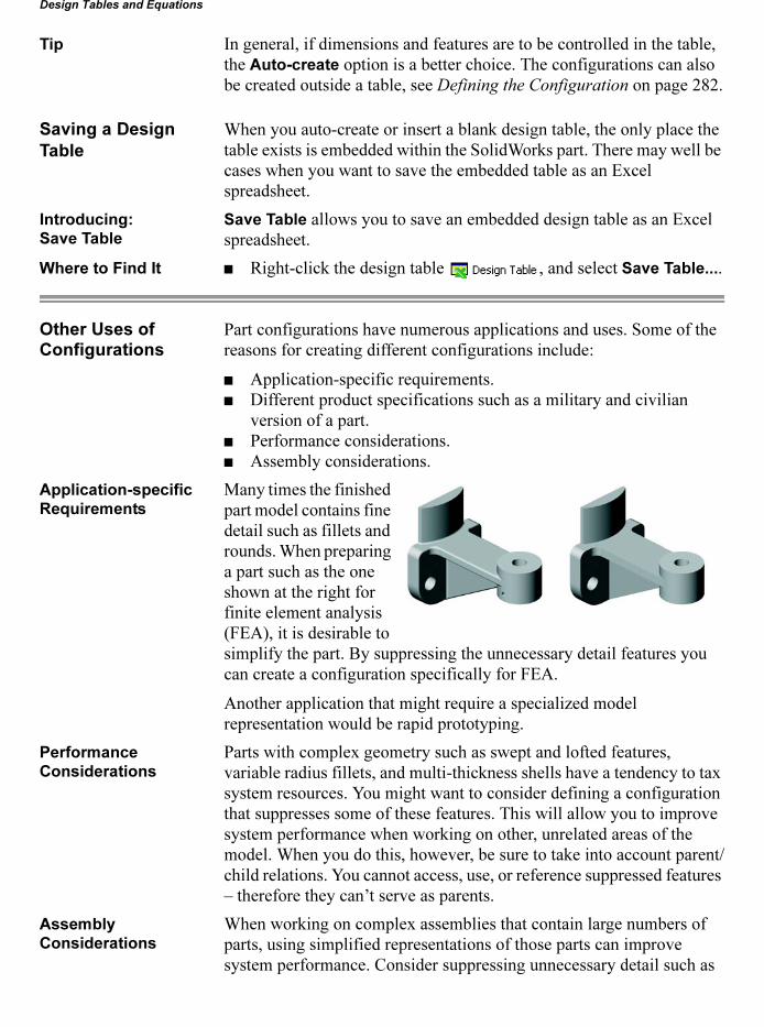
Many times the finished part model contains fine detail such as fillets and rounds. When preparing a part such as the one shown at the right for finite element analysis (FEA), it is desirable to simplify the part. By suppressing the unnecessary detail features you can create a configuration specifically for FEA.
Another application that might require a specialized model representation would be rapid prototyping.
Performance
Considerations
Parts with complex geometry such as swept and lofted features, variable radius fillets, and multi-thickness shells have a tendency to tax system resources. You might want to consider defining a configuration that suppresses some of these features. This will allow you to improve system performance when working on other, unrelated areas of the model. When you do this, however, be sure to take into account parent/child relations. You cannot access, use, or reference suppressed features – therefore they can’t serve as parents.
Assembly
Considerations
When working on complex assemblies that contain large numbers of parts, using simplified representations of those parts can improve system performance. Consider suppressing unnecessary detail such as

SolidWorks 2006 Training Manual Lesson 10Design Tables and Equations
Modeling Strategies for Configurations 319
fillets, leaving only critical geometry that is needed for mating, interference checking, and defining fit and function. When you add a component to an assembly, the Insert, Component, From File... browser allows you to choose the configuration of the part to be shown. To take best advantage of this, you have to plan ahead, defining and saving the configuration when the component is built.
Similar parts that have the same basic shape can be defined as different configurations and used in the same assembly. The part shown at the right has two configurations. For an example showing how to use two different configurations of a part within an assembly see Using
Part Configurations in
Assemblies on page 396.
Modeling Strategies for Configurations
When you model a part that will be used with configurations – whether or not it is driven by a design table – you should give some thought to what you want the configurations to control. Consider, for example, the part used in the previous procedure.
One way a part like this can be modeled is to make a single sketch of the profile and build the part as a single revolved feature.
Although that approach seems efficient, having all the information contained in a single, monolithic feature really limits your flexibility. By breaking the part down into smaller, individual features, you gain the flexibility of being able to suppress features such as fillets or cuts.

Lesson 10 SolidWorks 2006 Training ManualDesign Tables and Equations
320 More About Making Drawings
More About Making Drawings
Drawings were first introduced in Lesson 3. In this section we will explore some additional detailing topics. These topics include: Named
Views, Section Views, Detail Views and Ordinate Dimensions.
1 Open the drawing named Part_DT.
Drawing Properties
The drawing properties control many characteristics of each drawing sheet. Settings can be different for each drawing sheet.
Introducing:
Drawing Properties
View scale, paper size, sheet format and type of projection are all set or changed through the Sheet Setup dialog.
Where to Find It � With the cursor over the drawing, right-click and select Properties....
� Or, right-click the sheet icon in the FeatureManager, and select Properties....
2 Sheet setup.
Right-click the sheet, and select Properties.... Set the Standard
sheet size toB-Landscape, Scale to 1:2 and clear Display
sheet format. Click OK.
SolidWorks 2006 Training Manual Lesson 10Design Tables and Equations
More About Making Drawings 321
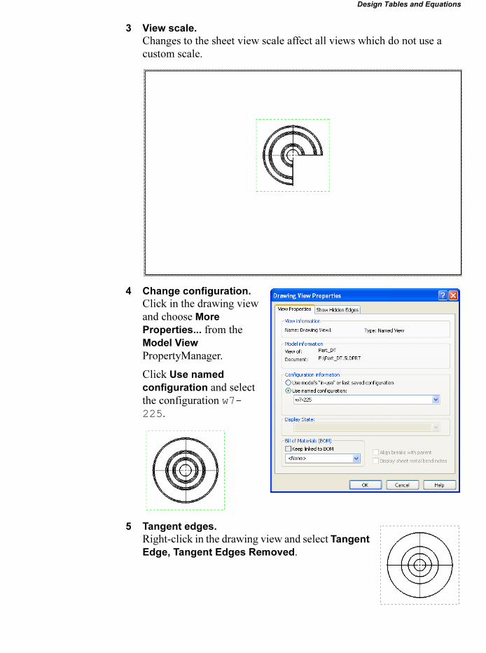
3 View scale.
Changes to the sheet view scale affect all views which do not use a custom scale.
4 Change configuration.
Click in the drawing view and choose More
Properties... from the Model View PropertyManager.
Click Use named
configuration and select the configuration w7-225.
5 Tangent edges.
Right-click in the drawing view and select Tangent
Edge, Tangent Edges Removed.

Lesson 10 SolidWorks 2006 Training ManualDesign Tables and Equations
322 More About Making Drawings
Simple Section View
You can create several types of section views. The simple section view uses a single line to form the cutting plane.
Introducing:
Section View
Section View creates a full or partial section view based on a cutting line and a direction. A single sketch line is used for the section line.
The fastest way to create the section is to click the tool first. This switches on the line tool for sketching the section line. When the line is completed, a preview of the section view appears.
Where to Find It � From the menu click Insert, Drawing View, Section.
� Or, on the Drawing toolbar click the Section View tool.
6 Click the Section View tool.
Click Section View . In the Top view, sketch a vertical line through the center of the part. Use the cursor feedback to align the line with the axis that runs through the center of the part. The line should extend well beyond the extents of the part.
7 Place the section view.
Move the cursor to the left of the view and place the section view by clicking the left mouse button.
The drawing view Section A-A is aligned to the source view and comes with a label beneath it. The cross hatching is automatic and reflects the type specified in the part document under Tools, Options, System Options,
Drawings, Area Hatch/Fill.
Detail Views Detail Views can be created using a closed sketched shape in an activated source view. The detail can use a scale multiplier to scale it n times larger than its source, default 2x. The contents of the detail view is determined by what is enclosed within the sketch. The sketch must be a closed contour but can be constructed of any sketch geometry types.
Introducing:
Detail View
Detail View creates a new view of an area enclosed by a set of closed sketch geometry.

SolidWorks 2006 Training Manual Lesson 10Design Tables and Equations
More About Making Drawings 323
The fastest way to create the detail is to click the tool first. This switches on the circle tool for sketching the detail circle. When the circle is completed, the detail appears.
Where to Find It � From the menu click Insert, Drawing View, Detail.
� Or, on the Drawing toolbar click the tool.
8 Sketch the detail circle.
Click the Detail tool. In the Section view, sketch a circle as shown.
Use the cursor feedback to place the center of the circle on an endpoint of an edge. Drag the circle diameter to enclose the lower portion of the part.
9 Place the detail.
Position the view on the drawing by clicking the left mouse button. Set the detail view state to Hidden Lines Removed.
10 Insert Model Items.
Model items can be added to all views, selected views or selected features within a view.
Select the section view, then click Insert, Model
Items....
Select Marked for drawing, Import from:
Entire model and Destination view(s)
(selected view).
Click OK.
Lesson 10 SolidWorks 2006 Training ManualDesign Tables and Equations
324 More About Making Drawings
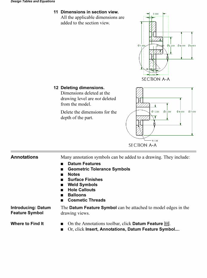
11 Dimensions in section view.
All the applicable dimensions are added to the section view.
12 Deleting dimensions.
Dimensions deleted at the drawing level are not deleted from the model.
Delete the dimensions for the depth of the part.
Annotations Many annotation symbols can be added to a drawing. They include:
� Datum Features
� Geometric Tolerance Symbols
� Notes
� Surface Finishes
� Weld Symbols
� Hole Callouts
� Balloons
� Cosmetic Threads
Introducing: Datum
Feature Symbol
The Datum Feature Symbol can be attached to model edges in the drawing views.
Where to Find It � On the Annotations toolbar, click Datum Feature .� Or, click Insert, Annotations, Datum Feature Symbol....

SolidWorks 2006 Training Manual Lesson 10Design Tables and Equations
More About Making Drawings 325
13 Add a Datum Feature Symbol.
Insert a Datum Feature with the Label A. Select the leftmost vertical model edge in the section view.
Click OK.
Ordinate Dimensions
In Lesson 3 you saw that you can manually add dimensions in the drawing document. These are reference dimensions, and are driven. That means you cannot edit the value of reference dimensions to change the model. However, changing a dimension in the model updates the driven dimension in the drawing.
SolidWorks supports several kinds of dimensions including Ordinate
Dimensions. Ordinate dimensions are a set of dimensions measured from a zero ordinate in a drawing or sketch. They are measured from the axis you select first. The type of ordinate dimension (horizontal, vertical, or angular) is defined by the orientation of the points you select.
Ordinate dimensions are automatically grouped to maintain alignment. When you drag any member of the group, all the members move together. To disconnect a dimension from the alignment group, right-click the dimension, and select Break Alignment.
If adjacent dimensions are very close together, the leaders are automatically jogged as needed to prevent overlapping text. Drag handles are displayed at the bends when you select an ordinate dimension with a bent leader. You can remove the bend, or add a bend to a different ordinate dimension.
Where to Find It � Click Horizontal Ordinate Dimension on the Dimensions/Relations toolbar.
� Click Tools, Dimensions, and Horizontal Ordinate.
Lesson 10 SolidWorks 2006 Training ManualDesign Tables and Equations
326 More About Making Drawings
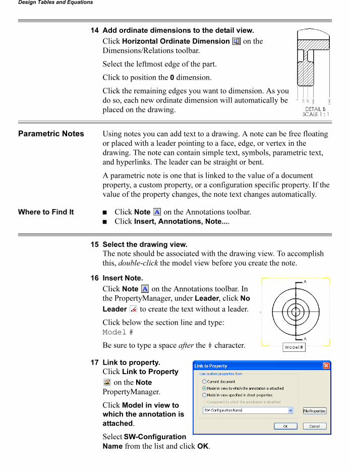
14 Add ordinate dimensions to the detail view.
Click Horizontal Ordinate Dimension on the Dimensions/Relations toolbar.
Select the leftmost edge of the part.
Click to position the 0 dimension.
Click the remaining edges you want to dimension. As you do so, each new ordinate dimension will automatically be placed on the drawing.
Parametric Notes Using notes you can add text to a drawing. A note can be free floating or placed with a leader pointing to a face, edge, or vertex in the drawing. The note can contain simple text, symbols, parametric text, and hyperlinks. The leader can be straight or bent.
A parametric note is one that is linked to the value of a document property, a custom property, or a configuration specific property. If the value of the property changes, the note text changes automatically.
Where to Find It � Click Note on the Annotations toolbar.� Click Insert, Annotations, Note....
15 Select the drawing view.
The note should be associated with the drawing view. To accomplish this, double-click the model view before you create the note.
16 Insert Note.
Click Note on the Annotations toolbar. In the PropertyManager, under Leader, click No
Leader to create the text without a leader.
Click below the section line and type:Model #
Be sure to type a space after the # character.
17 Link to property.
Click Link to Property
on the Note PropertyManager.
Click Model in view to
which the annotation is
attached.
Select SW-Configuration
Name from the list and click OK.
SolidWorks 2006 Training Manual Lesson 10Design Tables and Equations
More About Making Drawings 327
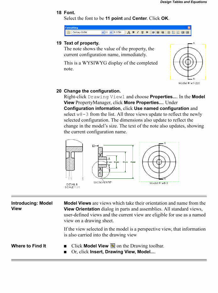
18 Font.
Select the font to be 11 point and Center. Click OK.
19 Text of property.
The note shows the value of the property, the current configuration name, immediately.
This is a WYSIWYG display of the completed note.
20 Change the configuration.
Right-click Drawing View1 and choose Properties.... In the Model
View PropertyManager, click More Properties.... Under Configuration information, click Use named configuration and select w8-3 from the list. All three views update to reflect the newly selected configuration. The dimensions also update to reflect the change in the model’s size. The text of the note also updates, showing the current configuration name.
Introducing: Model
View
Model Views are views which take their orientation and name from the View Orientation dialog in parts and assemblies. All standard views, user-defined views and the current view are eligible for use as a named view on a drawing sheet.
If the view selected in the model is a perspective view, that information is also carried into the drawing view
Where to Find It � Click Model View on the Drawing toolbar.� Or, click Insert, Drawing View, Model....
Lesson 10 SolidWorks 2006 Training ManualDesign Tables and Equations
328 More About Making Drawings
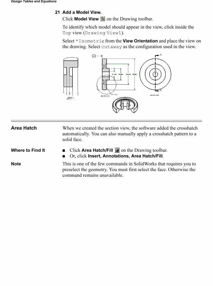
21 Add a Model View.
Click Model View on the Drawing toolbar.
To identify which model should appear in the view, click inside the Top view (Drawing View1).
Select *Isometric from the View Orientation and place the view on the drawing. Select cutaway as the configuration used in the view.
Area Hatch When we created the section view, the software added the crosshatch automatically. You can also manually apply a crosshatch pattern to a solid face.
Where to Find It � Click Area Hatch/Fill on the Drawing toolbar.� Or, click Insert, Annotations, Area Hatch/Fill.
Note This is one of the few commands in SolidWorks that requires you to preselect the geometry. You must first select the face. Otherwise the command remains unavailable.

SolidWorks 2006 Training Manual Lesson 10Design Tables and Equations
More About Making Drawings 329
22 Area Hatch.
Select the two cut faces of the model in the isometric view.
Click Area Hatch/Fill .
The Area Hatch/Fill dialog box appears. This allows you to change the style of the hatch pattern.
Click OK.
23 Edit the hatch pattern.
Click the leftmost section of area hatch. Change the Angle to 90° and click OK.
This gives a more pleasing appearance to the hatch pattern.
Design Tables in a Drawing
The design table of a part can be shown on a drawing sheet. After selecting a view of the part, click Insert,
Tables, Design Table... and place it on the drawing. Double-clicking the table opens the referenced part and the design table within it.

Lesson 10 SolidWorks 2006 Training ManualDesign Tables and Equations
330 In the Advanced Course...
24 Insert the design table.
Click inside one of the drawing views. Since a drawing can contain views of several different models, you have to identify from which part the design table will be inserted.
Click Design Table or click Insert, Tables, Design Table....
The design table appears in the upper left corner of the drawing. Drag it to where you want it on the drawing.
For more information about making drawings in SolidWorks, you
should attend the SolidWorks Essentials: Drawings course.
In the Advanced Course...
In the advanced course Advanced Assembly Modeling, the concept of Configurations is carried into assemblies.
Assemblies can have configurations that are created manually or through a design table. While part configurations focus on features, assembly configurations focus on components, mates, or assembly fea-tures. Assembly configurations can be used to control:
� Assembly Features� Components� Mates and Mate Dimensions
Design tables can also be used. At the assembly level there are more options available to control one or more component instances.
SolidWorks 2006 Training Manual
Exercise 40 331
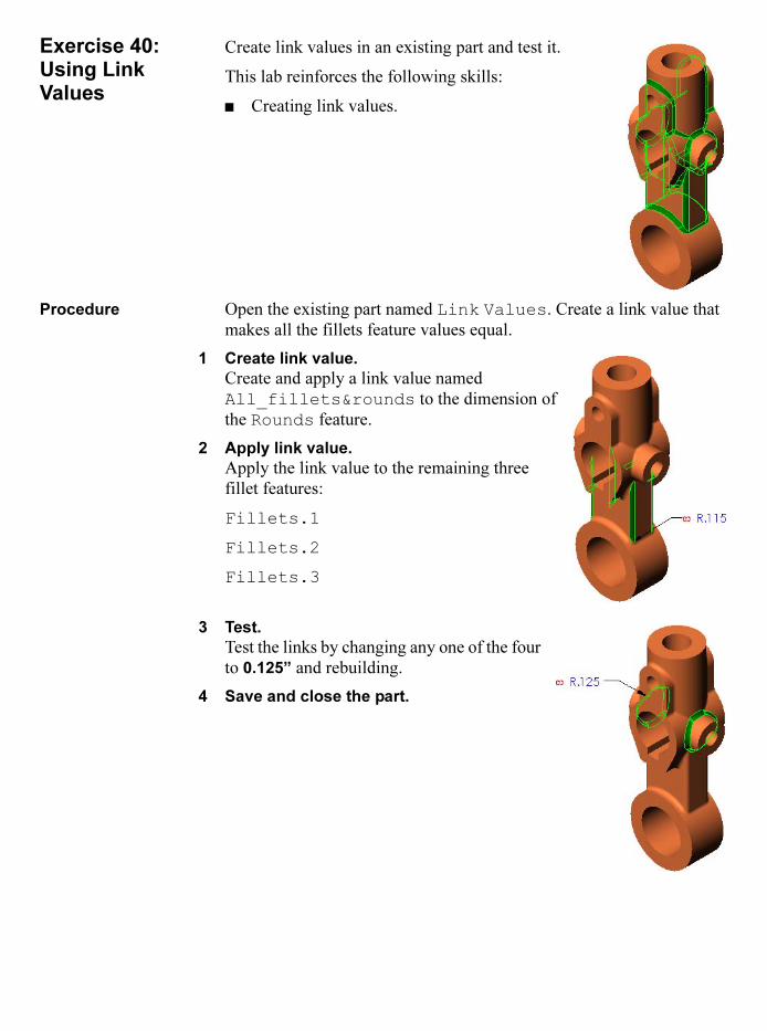
Exercise 40:Using Link Values
Create link values in an existing part and test it.
This lab reinforces the following skills:
� Creating link values.
Procedure Open the existing part named Link Values. Create a link value that makes all the fillets feature values equal.
1 Create link value.
Create and apply a link value named All_fillets&rounds to the dimension of the Rounds feature.
2 Apply link value.
Apply the link value to the remaining three fillet features:
Fillets.1
Fillets.2
Fillets.3
3 Test.
Test the links by changing any one of the four to 0.125” and rebuilding.
4 Save and close the part.

SolidWorks 2006 Training Manual
332 Exercise 41
Exercise 41:Using Equations
Create an equation using an existing part and test it.
This lab reinforces the following skills:
� Creating equations.
Procedure Open the existing part named Using Equations. The dimensions A, B and C shown above will be used to define the equation.
1 Write equation.
Write an equation that keeps the bolt circle diameter (A) centered between the outside edges of the hub (B) and flange (C). The (A) value should be driven.
2 Test equation.
Test the equation be changing the flange diameter to 12” and rebuilding the model. Test other values if you wish.
3 Save and close the part.
Tip If you are having trouble, the equation format should be:A=(C-B)/2+B.
A
B
C

SolidWorks 2006 Training Manual
Exercise 42 333
Exercise 42:Part Design Tables
Use an existing part as the basis for a design table. Use the dimensions and add them into a new design table.
This lab reinforces the following skills:
� Inserting design tables.� Editing design tables.� Adding properties.� Using configurations.
Procedure Open the existing part Part Design Table.
1 Design table.
Create a design table using Auto-create and edit it as shown.
2 Add dimensions.
CTRL-select all the dimensions, with the exception of D1@Main, in the Dimensions dialog.
Add them to the design table. The current values are added automatically.
3 Add feature.
Double-click the Holes feature to add it to the design table. The current state is added automatically.
4 Add configuration.
Type in the configuration name Size1 as shown. Copy the cells as shown.
SolidWorks 2006 Training Manual
334 Exercise 42
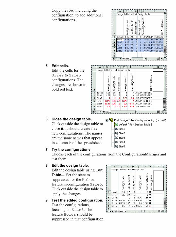
Copy the row, including the configuration, to add additional configurations.
5 Edit cells.
Edit the cells for the Size2 to Size5 configurations. The changes are shown in bold red text.
6 Close the design table.
Click outside the design table to close it. It should create five new configurations. The names are the same names that appear in column A of the spreadsheet.
7 Try the configurations.
Choose each of the configurations from the ConfigurationManager and test them.
8 Edit the design table.
Edit the design table using Edit
Table.... Set the state to suppressed for the Holes feature in configuration Size5. Click outside the design table to apply the changes.
9 Test the edited configuration.
Test the configurations, focusing on Size5. The feature Holes should be suppressed in that configuration.

SolidWorks 2006 Training Manual
Exercise 42 335
10 (Optional) Add
spreadsheet
functions.
Edit the Design Table to establish relationships between cells in the spreadsheet. Make the Side Radius (SideR) equal to half the center to center (CtoC) distance. For example, cell C3 will be = D3/2; cell C4 will be = D4/2 and so on.A USER_NOTE entry can be added to explain the relationship between the columns.
11 (Optional) Changes.
Make the Size3 configuration active. Double-click the Holes feature and change the value of the BoltH dimension to 0.375” for This Configuration. Click OK on the message box.
12 Bi-directional
changes.
The change is made to the active configuration for that dimension. The change to the model forces a change in the design table.
13 Save and close the
part.

SolidWorks 2006 Training Manual
336 Exercise 43
Exercise 43:Existing Configurations and Linked Design Tables
Use existing parts to automatically create design tables and link to external Excel spreadsheets.
This lab reinforces the following skills:
� Automatically creating design tables from existing configurations.
� Inserting design tables.� Linking to external design tables.
Auto-create Open the existing part named Auto-Create. It contains several configurations but no design table.
1 Auto-create.
Insert a design table using the Auto-
create option.
2 Design table.
A design table is generated from the existing configurations.
3 Save and close the part.
Link to External
Excel Spreadsheet
Open the existing part Linked. It contains no configurations except the Default.
4 From file.
Insert a design table using the From file option. Select the file Design Table.xls. Select the option Link to file.
5 Edit Excel file.
Open the linked Excel file Design Table.xls and add a new configuration G6 as shown.
6 Return to the part.
Save and close the spreadsheet. Return to the part to see the updates.
7 Save and close the part.

SolidWorks 2006 Training Manual
Exercise 44 337
Exercise 44:Designing for Configurations
Create a new part and design table. Design the part with the use of configurations and design tables in mind.
This lab reinforces the following skills:
� Modeling for configurations.� Creating design tables in Excel or within SolidWorks.� Using configurations.� Excel options.
Procedure Create a new part using the Part_IN template. Name the part Design for Configs.
1 Default configuration.
Create the basic shape of the part as a revolved feature using the dimensions shown.
2 Dimension names.
Rename the overall diameter (5”) dimension to Main_OD.
3 Groove Feature.
Create a cut feature to represent the groove. Name the feature Groove.
Rename the dimensions of the groove to Groove_ID, Groove_OD and Groove_Depth.
SolidWorks 2006 Training Manual
338 Exercise 44
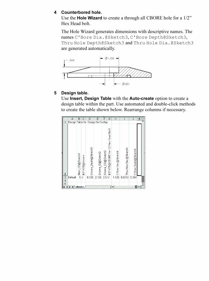
4 Counterbored hole.
Use the Hole Wizard to create a through all CBORE hole for a 1/2” Hex Head bolt.
The Hole Wizard generates dimensions with descriptive names. The names C'Bore Dia.@Sketch3, C'Bore Depth@Sketch3, Thru Hole Depth@Sketch3 and Thru Hole Dia.@Sketch3 are generated automatically.
5 Design table.
Use Insert, Design Table with the Auto-create option to create a design table within the part. Use automated and double-click methods to create the table shown below. Rearrange columns if necessary.
SolidWorks 2006 Training Manual
Exercise 44 339
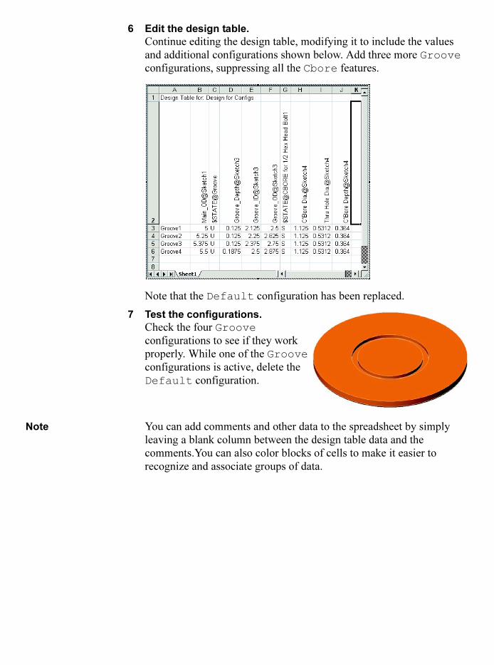
6 Edit the design table.
Continue editing the design table, modifying it to include the values and additional configurations shown below. Add three more Groove configurations, suppressing all the Cbore features.
Note that the Default configuration has been replaced.
7 Test the configurations.
Check the four Groove configurations to see if they work properly. While one of the Groove configurations is active, delete the Default configuration.
Note You can add comments and other data to the spreadsheet by simply leaving a blank column between the design table data and the comments.You can also color blocks of cells to make it easier to recognize and associate groups of data.

SolidWorks 2006 Training Manual
340 Exercise 44
8 Add more configurations.
Edit the design table again and add four more configurations for the Cbore. Yellow indicates copied information, bold red changed.
9 Save the part.

SolidWorks 2006 Training Manual
Exercise 45 341
Exercise 45:Drawings
Create a drawing of the part you built in the previous exercise.
This lab reinforces the following skills:
� Creating named views.� Creating a section view.� Showing different configurations of
a part in drawing views.� Creating a parametric note.� Adding dimensions and annotations.� Adding hole callouts.� Inserting a design table into a drawing.
Procedure Create an A-size drawing similar to the one shown below.

SolidWorks 2006 Training Manual
342 Exercise 45