ATTEMPTING TO ASSEMBLE OR OPERATE THE Black Opal Xtreme
35
User’s Manual: Black Opal Xtreme Models Flat Panel Display Systems File: UM-RMU-M-2296-D_1 Copyright. All Rights Reserved. Laserdyne Pty Ltd Author(s): MW,TW Authorised: TW Rev. Date: 14.2.14 Page: i User’s Manual READ THIS DOCUMENT THOROUGHLY BEFORE ATTEMPTING TO ASSEMBLE OR OPERATE THE Black Opal Xtreme Flat Panel Display Systems Treatment of this product other than as specified herein may result in: damage to the product or attached systems; invalidation of the warranty. The location of this document should always be known to all users of, and technical support personnel for, the Black Opal Xtreme. The information contained herein is proprietary to Laserdyne Pty Ltd. No part of this work may be reproduced or copied in any way without prior written permission of Laserdyne Pty Ltd. Note: specifications herein are subject to change without notice. CAUTIONS: • On receipt of your Black Opal Xtreme, immediately report any damage to packaging or contents to your supplier. • Ensure that all instructions in the separate Specifications and Set-up document applicable to your model are performed correctly, before attempting to operate the Black Opal Xtreme. • The system is in standby status whenever external power is applied. Do not leave the system in standby status for extended periods (remove external power). • Resetting the system should not be performed gratuitously, as the system may not have updated its EEPROM settings since the last setting change. • Avoid scratching, abrading or contaminating the surface of the display window; do not scrub.
Transcript of ATTEMPTING TO ASSEMBLE OR OPERATE THE Black Opal Xtreme

User’s Manual: Black Opal Xtreme Models Flat Panel Display Systems
File: UM-RMU-M-2296-D_1 Copyright. All Rights Reserved. Laserdyne Pty Ltd
Author(s): MW,TW Authorised: TW Rev. Date: 14.2.14 Page: i
User’s Manual
READ THIS DOCUMENT THOROUGHLY BEFORE ATTEMPTING TO ASSEMBLE OR OPERATE
THE
Black Opal Xtreme
Flat Panel Display Systems
Treatment of this product other than as specified herein may result in: damage to the product or attached systems; invalidation of the warranty.
The location of this document should always be known to all users of, and technical support personnel for, the Black Opal Xtreme. The information contained herein is proprietary to Laserdyne Pty Ltd. No part of this work may be reproduced or copied in any way without prior written permission of Laserdyne Pty Ltd. Note: specifications herein are subject to change without notice. CAUTIONS:
• On receipt of your Black Opal Xtreme, immediately r eport any damage to packaging or contents to your supplier.
• Ensure that all instructions in the separate Specif ications and Set-up document applicable to your model are performed cor rectly, before attempting to operate the Black Opal Xtreme.
• The system is in standby status whenever external p ower is applied. Do not leave the system in standby status for extended periods (remove external power).
• Resetting the system should not be performed gratui tously, as the system may not have updated its EEPROM settings sin ce the last setting change.
• Avoid scratching, abrading or contaminating the sur face of the display window; do not scrub.
User’s Manual: Black Opal Xtreme Models Flat Panel Display Systems
File: UM-RMU-M-2296-D_1 Copyright. All Rights Reserved. Laserdyne Pty Ltd
Author(s): MW,TW Authorised: TW Rev. Date: 14.2.14 Page: ii
Tracking Records This document is appropriate for the following product
configurations:
Model: all Xtreme models
Initial Configuration Number: 1xxx-10x-xxx-1xx-xxx

User’s Manual: Black Opal Xtreme Models Flat Panel Display Systems
File: UM-RMU-M-2296-D_1 Copyright. All Rights Reserved. Laserdyne Pty Ltd
Author(s): MW,TW Authorised: TW Rev. Date: 14.2.14 Page: iii
TABLE OF CONTENTS
Chapter Page 1 INTRODUCTION 1-1 1.1 Scope 1-1 1.2 Document Structure 1-1 2 SAFETY 2-1 2.1 Electrical Safety 2-1 2.2 System Protection 2-1 3 PACKING, HANDLING, STORAGE & TRANSPORTATION 3-1 3.1 Packing, Unpacking and Inspection 3-1 3.2 Handling 3-1 3.3 Storage 3-1 3.4 Transportation 3-1 4 SYSTEM DESCRIPTION 4-1 4.1 General Purpose 4-1 4.2 General Description 4-1 4.2.1 General 4-1 4.2.2 Display 4-1 4.2.3 Auto Backlight Reduction 4-1 4.2.4 Upgrades 4-2 4.2.5 Additional Features 4-2 4.3 System Contents 4-2 5 SYSTEM SPECIFICATIONS & SET-UP 5-1 6 OPERATION 6-1 6.1 Controls 6-1 6.2 Indicators 6-2 6.3 Button Labelling, Adjustments & Menu Presentation 6-2 6.4 Operating Procedures 6-3 6.4.1 Start-up 6-3 6.4.1.1 Starting Up 6-3 6.4.1.2 The Boot-up Sequence 6-4 6.4.1.3 Bypassing the Boot-up Sequence 6-4 6.4.2 Primary Button Functions 6-5 6.4.3 Scroll/Adjust Button Functions 6-6 6.4.3.1 Adjust Image Enhancement 6-6 6.4.3.2 Adjust Digital Zoom 6-6

User’s Manual: Black Opal Xtreme Models Flat Panel Display Systems
File: UM-RMU-M-2296-D_1 Copyright. All Rights Reserved. Laserdyne Pty Ltd
Author(s): MW,TW Authorised: TW Rev. Date: 14.2.14 Page: iv
6.4.4 Reset 6-6 6.4.5 Menus 6-7 6.4.5.1 Main Menu 6-7 6.4.5.2 Video Menu 6-9 6.4.5.3 VGA Menu 6-10 6.4.5.4 Settings Menu 6-11 6.4.5.5 Defaults Menu 6-12 6.4.5.6 MemorEyes Menu 6-13 6.4.6 Working with Menus - How to 6-13 6.4.6.1 For Video 6-14 6.4.6.1.1 Adjust Contrast, Brightness and/or Colour Saturation 6-14 6.4.6.1.2 Select Colour Option for Display 6-14 6.4.6.2 For VGA 6-14 6.4.6.2.1 Correct Native VGA Image for Contrast, Brightness and/or Phase 6-14 6.4.6.3 Restore Set-up Defaults 6-15 6.4.6.4 Reboot the System 6-15 6.4.6.5 Set the System to Standby 6-15 6.4.7 Shut-Down 6-15 6.5 Special Functions & Modes 6-15 7 GENERAL MAINTENANCE 7-1 7.1 General Cleaning and Care 7-1 7.2 Replacing Desiccant 7-1 APPENDICES
A Faultfinding Guide A-1 B Set-up Menus B-1 LIST OF FIGURES
Figure 6-1: Controls and Indicators (typical) 6-1 Figure 6-2: Main Menu Structure 6-7 Figure 6-3: Main Menu Maximum Entries Structure 6-8 Figure 6-4: SD Video Menu Structure 6-9 Figure 6-5: VGA Menu Structure 6-10 Figure 6-6: Settings Menu Structure 6-11 Figure 6-7: Defaults Menu Structure 6-12

User’s Manual: Black Opal Xtreme Models Flat Panel Display Systems
File: UM-RMU-M-2296-D_1 Copyright. All Rights Reserved. Laserdyne Pty Ltd
Author(s): MW,TW Authorised: TW Rev. Date: 14.2.14 Page: 1-1
1 INTRODUCTION
1.1 Scope
This User’s Manual is designed for the operator of the Black Opal Xtreme display models. It contains set-up, operating, and user-level faultfinding and maintenance information.
1.2 Document Structure
This manual is structured to take the reader through safety observations, system description and specifications to the set-up, operation and general maintenance of the Black Opal Xtreme. There is no separate maintenance document for the Black Opal Xtreme - relevant maintenance information is contained in this User’s Manual. Some diagrams may be made available to the original purchaser of the Black Opal Xtreme, depending upon the level of maintenance undertaken by the user.

User’s Manual: Black Opal Xtreme Models Flat Panel Display Systems
File: UM-RMU-M-2296-D_1 Copyright. All Rights Reserved. Laserdyne Pty Ltd
Author(s): MW,TW Authorised: TW Rev. Date: 14.2.14 Page: 2-1
2 SAFETY
2.1 Electrical Safety The Black Opal Xtreme is designed to operate from low voltage dc power. Once installed, there are no safety procedures required to protect the operator from the display itself. NOTE: the On/Off button switches the unit from sta ndby to operating
status, it does not cut the unit off entirely from the external power input.
2.2 System Protection
The system is internally protected against: • reverse polarity; • over-voltage; • over-current.


User’s Manual: Black Opal Xtreme Models Flat Panel Display Systems
File: UM-RMU-M-2296-D_1 Copyright. All Rights Reserved. Laserdyne Pty Ltd
Author(s): MW,TW Authorised: TW Rev. Date: 14.2.14 Page: 3-1
3 PACKING, HANDLING, STORAGE AND TRANSPORTATION
CAUTION: On receipt of your Black Opal Xtreme, imm ediately report any damage to packaging or contents to your supplie r.
3.1 Packing, Unpacking and Inspection
To unpack on first receipt: 1. carefully open the outer packaging, do not slit cartons deeper than sealing tape; 2. remove the Black Opal Xtreme components and any Manuals and ancillary items
from the carton; 3. remove the display from its plastic bag/wrap; 4. remove the protective sheet from the front of the display; 5. retain packing materials if required for future use. Packing is in the reverse order.
3.2 Handling
Touching or abrading any exposed optical surface is to be avoided. Environmental conditions specified in this manual should not be exceeded.
3.3 Storage
The equipment may be stored in its original packaging provided that packing and handling conditions described in this manual are observed. The packaged unit should not be stored in damp conditions or damage to the packaging will result. The unpackaged unit should not be stored in areas where conditions may exceed the product’s environmental specification.
3.4 Transportation
All items should be packed as described in this manual. Road, rail or air transport are suitable transport methods.


User’s Manual: Black Opal Xtreme Models Flat Panel Display Systems
File: UM-RMU-M-2296-D_1 Copyright. All Rights Reserved. Laserdyne Pty Ltd
Author(s): MW,TW Authorised: TW Rev. Date: 14.2.14 Page: 4-1
4 SYSTEM DESCRIPTION
4.1 General Purpose
The Black Opal Xtreme models have been engineered for a wide range of land-, sea- or air-borne display applications including remote/indirect viewing of video images generated by day, night or thermal cameras.
4.2 General Description
4.2.1 General
Each Black Opal Xtreme model consists of a LCD, a microprocessor unit (computer) and power & control electronics. Each model features MultiVision, allowing for multiple analogue and digital inputs, and providing simultaneous display of multiple inputs (model and connector dependent – see specifications). All items are housed within a rugged enclosure containing heating and cooling mechanisms. The LCD is protected by a tough, antireflection-coated window which also provides EMI/EMC shielding. All models are button operated. 4.2.2 Display
Images are displayed on a backlit LCD that may be viewed in full direct sunlight down to full darkness and feature backlight settings suitable for low light viewing, for viewing with Night Vision Devices and completely off for black-out conditions. 4.2.3 Auto Backlight Reduction
To reduce power consumption, and as part of the Black Opal Xtreme thermal management scheme, the backlight will automatically reduce to 300 nits if:
• the current backlight setting is greater than 300 nits; and
• no button has been pressed for more than 120 seconds and the internal temperature is above a preset limit.
Pressing any of buttons 1 to 5 will cause the system to return to the current backlight setting.

User’s Manual: Black Opal Xtreme Models Flat Panel Display Systems
File: UM-RMU-M-2296-D_1 Copyright. All Rights Reserved. Laserdyne Pty Ltd
Author(s): MW,TW Authorised: TW Rev. Date: 14.2.14 Page: 4-2
4.2.4 Upgrades
The Black Opal Xtreme has been designed so that software upgrades can be downloaded easily via a PC. 4.2.5 Additional Features
NOTE: Image Enhancement and Digital Zoom are avail able whenever the main window in a Screen Lay-out is video, not P C input.
Black Opal displays have several features designed to increase the effectiveness of surveillance, sighting and security systems, including:
Image Enhancement: video inputs are compensated for obscuration (e.g. rain, fog, snow, mist or smoke) within an adjustable central window where contrast and colour are enhanced. For a chosen window size, the enhancement is applied to that portion of the displayed image; Digital Zoom: a fully X & Y interpolated “smart” zoom, not merely pixel multiplying, yields a clear zoomed image without the blocky “pixelated” appearance often seen with digital zooming; and Freeze Frame: freezes the current prime video channel while leaving live any video inset. Colourisation: applies preloaded colour palettes to monochrome imagery. Motion (“edge tearing”) compensation: minimises the jagged edges that can occur with motion in video on LCDs.
4.3 System Contents
The Black Opal Xtreme system consists of: 1 x Black Opal Xtreme unit; 1 x User’s Manual; and 1 x Specification and Set-up document. plus any options that the purchaser has elected to acquire. NOTE: the purchaser must supply the appropriate Po wer, Video and
VGA Cable Assemblies.

User’s Manual: Black Opal Xtreme Models Flat Panel Display Systems
File: UM-RMU-M-2296-D_1 Copyright. All Rights Reserved. Laserdyne Pty Ltd
Author(s): MW,TW Authorised: TW Rev. Date: 14.2.14 Page: 5-1
5 SYSTEM SPECIFICATIONS & SET-UP
The specifications and set-up procedures for your model of Black Opal Xtreme are presented in a separate Specifications & Set-up document provided with your unit. CAUTION: ensure that all instructions in the separa te Specifications
and Set-up document applicable to your model are performed correctly, before attempting to operate t he Black Opal Xtreme.


User’s Manual: Black Opal Xtreme Models Flat Panel Display Systems
File: UM-RMU-M-2296-D_1 Copyright. All Rights Reserved. Laserdyne Pty Ltd
Author(s): MW,TW Authorised: TW Rev. Date: 14.2.14 Page: 6-1
6 OPERATION
6.1 Controls
The display has 9 points of control (model dependent), being a horizontal array of function and up/down buttons located on the bottom of the front face of the unit, and an on/off button and a day/night button located elsewhere on the front face - these are momentary (one result per press) sealed, backlit buttons. A typical configuration is shown below. In all cases, there are 5 Function Buttons, and up/down buttons. The functions of the five Function Buttons vary depending upon the screen being displayed and the level of customisation in the system software. In every case, the available button function is displayed beside the button on the LCD. The up/down buttons are available whenever a setting can be varied over a range. Such settings include backlight intensity, display settings and digital zoom settings. Up/down buttons are generally referred to as scroll/adjust buttons throughout this manual, depending upon the context.
Figure 6-1: Controls and Indicators (typical)
On/Off Button
Function Buttons: 1 to 5
Scroll/Adjust Buttons
User’s Manual: Black Opal Xtreme Models Flat Panel Display Systems
File: UM-RMU-M-2296-D_1 Copyright. All Rights Reserved. Laserdyne Pty Ltd
Author(s): MW,TW Authorised: TW Rev. Date: 14.2.14 Page: 6-2
6.2 Indicators
The illumination behind the buttons operates as thermal status indicators in the case where the temperature is too hot or too cold for the unit to operate. If the display’s internal temperature is too low, Warm-up mode will be engaged, and the button backlighting will blink at a slow rate (around 0.5Hz). Once the internal temperature is within operating parameters the button backlight will operate as normal. If the display’s internal temperature is too high, it will shut down and the button backlight will blink at a fast rate (around 2Hz). Once the internal temperature is within operating parameters the button backlight will operate as normal.
6.3 Button Labelling, Adjustments & Menu Presentati on
• If no button has been activated for about five seconds, and no menus have been entered, the button labels will be withdrawn from the screen, however scroll/adjust buttons will still be active for the current adjustable parameter. Pressing any Function Button (buttons 1 to 5) will restore the labels without initiating a new function.
• In any menu, button 2 becomes EXIT, button 5 becomes ENTER and buttons 1,
3 & 4 are disabled. • In any menu, the BACK item will return to the previous menu. • Select menu items using the scroll/adjust buttons. Press ENTER to enable the
selection. Press EXIT to abandon the menu and any unfinished adjustments. • The scroll/adjust buttons will be labelled as “-PARAMETER+” to indicate which
parameter is selected for adjustment. • Backlight can be adjusted at any time by using the scroll/adjust buttons, unless
ZOOM or MENU has been selected. • Zoom can be adjusted at any time by using the scroll/adjust buttons, unless
BACKLT or MENU has been selected.
User’s Manual: Black Opal Xtreme Models Flat Panel Display Systems
File: UM-RMU-M-2296-D_1 Copyright. All Rights Reserved. Laserdyne Pty Ltd
Author(s): MW,TW Authorised: TW Rev. Date: 14.2.14 Page: 6-3
• Various display settings can be adjusted, once they have been selected through the menu structure, by using the scroll/adjust buttons.
• Once ENTER has been pressed the previous menu will be presented if no
concurrent options are available, else the current menu will be maintained if more than one item in it can be enabled or adjusted concurrently.
• Whenever button labels are displayed, the name of the current screen lay-out is
also displayed above the top-most button label.
6.4 Operating Procedures
CAUTION: the system is in standby status whenever e xternal power is applied. Do not leave the system in standby status for extended periods (remove external power).
6.4.1 Start-up
6.4.1.1 Starting Up
• Before proceeding check that all connections and mountings are secure and appropriate, then switch on external power to the display.
• Select a suitable button backlight intensity by pressing up/down PRIOR to
pressing the On/Off button.
• Press the On/Off button to power up the system. NOTE: The default backlight mode and level used on power-up can be controlled in a number of ways depending on the factory-configured power-up configuration as follows:
• If the Day/Night button is held down when the On/Off button is pressed, then NIGHT mode is enabled for this power-up, regardless of any factory configured boot mode.
• Otherwise, pressing the power button will select one of the 4 factory-configured backlight modes as follows: a. Auto mode: In this mode, the light sensor on the front of the display is
used to determine the correct mode. If the detected light level is below a threshold, then NIGHT mode is selected, otherwise DAY mode is selected. In both cases the level is set to 50%.

User’s Manual: Black Opal Xtreme Models Flat Panel Display Systems
File: UM-RMU-M-2296-D_1 Copyright. All Rights Reserved. Laserdyne Pty Ltd
Author(s): MW,TW Authorised: TW Rev. Date: 14.2.14 Page: 6-4
b. User Mode: In this mode, the previously set button backlight level (using up/down PRIOR to pressing the On/Off button) selects the mode and intensity for the main backlight. The 3 highest settings for the button backlight select DAY mode (100%, 50%, 10%), while the lower button backlight settings select NIGHT mode, in main backlight default setting decreasing with button backlight setting. This user adjustable setting is permanent, and will be used on all subsequent power-ups unless otherwise changed.
c. Fixed Mode: In this mode, the default backlight mode and level will be specified and set to suit a particular program requirement.
d. Ramp-up Mode: In this mode, the backlight slowly ramps up through NIGHT and then DAY modes, and stops rising when any button is pressed. If no button is pressed, then DAY mode at maximum brightness is selected.
6.4.1.2 The Boot-up Sequence
The boot-up sequence has several phases, all of which can be customized to suit customer requirements. The first phase is the initial backlight setting. There are several options for this (one of which is pre-configured to suit customer requirements), including a slow ramp up of backlight intensity (which is suspended by a button press), or a specific level and mode (i.e. day or night modes). Unless otherwise specified, the backlight will be set to DAY mode, and at a suitable brightness for visibility under most conditions. The last phase is the loading of the default screen layout. This can be either the last selected layout, or a fixed layout. This is pre-configured prior to delivery to suit specific customer requirements. 6.4.1.3 Bypassing the Boot-up Sequence
If the Ramp-up Mode has been selected, this can be bypassed by pressing any of buttons 2 to 5 on power-up and holding it until the backlight shows. The number of the button pressed determines the backlight level, with button 5 being maximum, button 4 being less intense, button 3 being low intensity, and button 2 being the NVG compatible mode. Performing this action not only sets the initial backlight level without ramping up, it also skips the logo and version presentations.

User’s Manual: Black Opal Xtreme Models Flat Panel Display Systems
File: UM-RMU-M-2296-D_1 Copyright. All Rights Reserved. Laserdyne Pty Ltd
Author(s): MW,TW Authorised: TW Rev. Date: 14.2.14 Page: 6-5
NOTE: this method of setting a backlight level appl ies only to the boot-up sequence, the normal method of adjusting ba cklight level is using the + and – buttons.
6.4.2 Primary Button Functions
After boot-up: • Press MENU (button 1) to access menu functions; or • Press LAYOUT (button 2) to show the predefined screen lay-outs, then press the
appropriate button to select the desired lay-out (see appendices for instructions on how to create screen a lay-out under the Set-up menu structure and for descriptions of lay-outs); or
• Press ENH (button 3) to enable image enhancement and allow enhancement-
window adjustment (only available for video) (will be replaced by NO ENH).; or • Press ZOOM (button 4) to allow digital zoom adjustment (will be replaced by
BACKLT) (only available for video); or • Press FREEZE (button 5) to freeze image (will be replaced by UNFREEZE).
• Press the On/Off button (short press) to cycle the displayed menu between
normal functions and Memoreyes functions (if a Memoreyes is detected).
• Hold the On/Off button for 2s to power-down the display
NOTE: you can: freeze a zoomed, enhanced or zoomed-&-enhanced im age;
enhance a frozen image; or zoom a frozen, enhanced, frozen & enhanced image.
NOTE: Image Enhancement and Digital Zoom are avail able whenever
the main window in a Screen Lay-out is video, not P C input. NOTE: If the Memoreyes menu option is selected, the n the primary
buttons assume new functions. Use the EXIT button t o return to normal primary button functions.
NOTE: If the video format changes from that specifi ed in the layout,
use the zoom feature to re-format the image on the screen.

User’s Manual: Black Opal Xtreme Models Flat Panel Display Systems
File: UM-RMU-M-2296-D_1 Copyright. All Rights Reserved. Laserdyne Pty Ltd
Author(s): MW,TW Authorised: TW Rev. Date: 14.2.14 Page: 6-6
6.4.3 Scroll/Adjust Button Functions
The following sections describe the use of the scroll/adjust buttons to adjust the (non-menu) parameter associated with a primary button function. 6.4.3.1 Adjust Image Enhancement
• Press ENH to enable image enhancement. • Use scroll/adjust buttons (now labelled -ENH+) to select desired enhancement-
window size (will default to that last selected). NOTE: window size has an effect on enhancement as o nly the
portion of the image contained in the window is sam pled. A smaller window can yield a more profound result if it contains a narrower spread of native contrasts than a larger one.
NOTE: If zoom is selected on an enhanced image, the enhancement
parameters are held constant. 6.4.3.2 Adjust Digital Zoom
The unit multiple digital zoom settings. When the unit is turned on the zoom defaults to the lowest available setting. • Press ZOOM to enable the scroll/adjust buttons for digital zoom adjustment. • Use scroll/adjust buttons (now labelled -ZOOM+) to select desired zoom setting.
6.4.4 Reset
The system may be reset by holding down the power button for at least 8s. CAUTION: resetting the system should not be perform ed gratuitously,
as the system may not have updated its EEPROM setti ngs since the last setting change.

User’s Manual: Black Opal Xtreme Models Flat Panel Display Systems
File: UM-RMU-M-2296-D_1 Copyright. All Rights Reserved. Laserdyne Pty Ltd
Author(s): MW,TW Authorised: TW Rev. Date: 14.2.14 Page: 6-7
6.4.5 Menus
There are two menu structures: the User’s menu structure and the Set-up menu structure. The Set-up menu structure is not used in normal operation. It is only available when a special sequence is performed. It allows basic and advanced set-up of inputs, outputs, corrections and adjustments. The settings selected in the Set-up menu structure become the default settings for parameters in the User’s menu structure. The Set-up menu structure is described in an appendix to this User’s Manual. The User’s menu structure is available during normal viewing and use. It allows the operator to perform basic corrections and adjustments effecting the appearance of the display. Settings made under the User’s menu structure can be optionally retained until the next change, even during shut-down and start-up. The user can, at any time, return all parameters to the default settings selected under the Set-up menu structure. The ability for the system to retain the settings can be factory enabled. 6.4.5.1 Main Menu
The contents of the Main menu will depend on the features enabled for the current layout (i.e. which input channels are shown on-screen for the current layout). The Some variants of the Main menus are shown in the following diagrams
Figure 6-2: Main Menu General Structure
Main Menu
Layout-specific options…
Standard options…
User’s Manual: Black Opal Xtreme Models Flat Panel Display Systems
File: UM-RMU-M-2296-D_1 Copyright. All Rights Reserved. Laserdyne Pty Ltd
Author(s): MW,TW Authorised: TW Rev. Date: 14.2.14 Page: 6-8
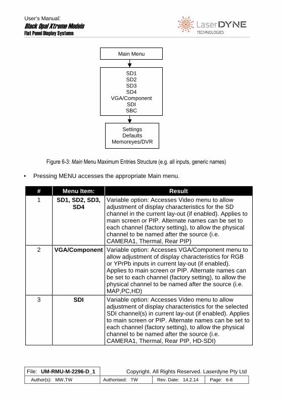
Figure 6-3: Main Menu Maximum Entries Structure (e.g. all inputs, generic names) • Pressing MENU accesses the appropriate Main menu.
# Menu Item: Result 1 SD1, SD2, SD3,
SD4 Variable option: Accesses Video menu to allow adjustment of display characteristics for the SD channel in the current lay-out (if enabled). Applies to main screen or PIP. Alternate names can be set to each channel (factory setting), to allow the physical channel to be named after the source (i.e. CAMERA1, Thermal, Rear PIP)
2 VGA/Component Variable option: Accesses VGA/Component menu to allow adjustment of display characteristics for RGB or YPrPb inputs in current lay-out (if enabled). Applies to main screen or PIP. Alternate names can be set to each channel (factory setting), to allow the physical channel to be named after the source (i.e. MAP,PC,HD)
3 SDI Variable option: Accesses Video menu to allow adjustment of display characteristics for the selected SDI channel(s) in current lay-out (if enabled). Applies to main screen or PIP. Alternate names can be set to each channel (factory setting), to allow the physical channel to be named after the source (i.e. CAMERA1, Thermal, Rear PIP, HD-SDI)
Main Menu
SD1 SD2 SD3 SD4
VGA/Component SDI SBC
Settings Defaults
Memoreyes/DVR

User’s Manual: Black Opal Xtreme Models Flat Panel Display Systems
File: UM-RMU-M-2296-D_1 Copyright. All Rights Reserved. Laserdyne Pty Ltd
Author(s): MW,TW Authorised: TW Rev. Date: 14.2.14 Page: 6-9
# Menu Item: Result 4 SBC Variable option: Accesses Video menu to allow
adjustment of display characteristics for the SBC (single-board computer) channel in current lay-out (if installed). Applies to main screen or PIP. Alternate names can be set to each channel (factory setting), to allow the physical channel to be named after the source (i.e. DVR)
5 SETTINGS Standard option: Accesses Settings menu for display-wide settings (such as colourisation).
6 DEFAULTS Standard option: Accesses Defaults menu for restoration of Set-up defaults to screen-layout(s), and allows the system to be rebooted or set to standby.
7 Memoreyes/DVR Variable option: Changes button 1..5 functions to allow access to external recorder functions.
• Select the desired item and press ENTER.
6.4.5.2 Video Menu (variable between layouts)
The SD1, SD2, SD3, SD4 Menu is accessed via a Main menu when the current screen lay-out contains a full-screen video channel. Note that if the system is configured to also operate a Memoreyes DVR, then an additional menu option for the control of the recorder will also appear.
Figure 6-4: SD Video Menu Structure • Selecting the Video menu presents the menu items GAIN, LEVEL,
SATURATION.
Saturation Level Gain
SDn menu

User’s Manual: Black Opal Xtreme Models Flat Panel Display Systems
File: UM-RMU-M-2296-D_1 Copyright. All Rights Reserved. Laserdyne Pty Ltd
Author(s): MW,TW Authorised: TW Rev. Date: 14.2.14 Page: 6-10
# Menu Item Result 1 Gain Allows the adjustment of gain value for display
contrast. 2 Level Allows the adjustment of offset value for display
brightness (as opposed to backlight intensity). 3 Saturation Allows the adjustment of colour intensity (similar to
the “colour” feature on a TV). • Select the desired item and press ENTER. • In the case of GAIN, LEVEL or SATURATION, adjust value and press ENTER. 6.4.5.3 VGA Menu
The VGA/Component Menu is accessed via a Main menu when the current screen lay-out has VGA (PC input) or Component (YPrPb).
Figure 6-5: VGA Menu Structure • Selecting the VGA menu presents the menu items GAIN, OFFSET, PHASE and
POSITION, and if the VGA menu was accessed from a full screen VGA lay-out with no PIP (i.e. accessed via the MENU button), DEFAULTS.
# Menu Item Result 1 Gain Allows the adjustment of gain value for display
contrast. 2 Offset Allows the adjustment of offset value for display
brightness (as opposed to backlight intensity). 3 Phase Allows the adjustment and setting of phase value.
• Select the desired item and press ENTER. • In the case of GAIN, OFFSET or PHASE, adjust value and press ENTER.
Phase Offset Gain
VGA menu

User’s Manual: Black Opal Xtreme Models Flat Panel Display Systems
File: UM-RMU-M-2296-D_1 Copyright. All Rights Reserved. Laserdyne Pty Ltd
Author(s): MW,TW Authorised: TW Rev. Date: 14.2.14 Page: 6-11
NOTE: the VGA GAIN and OFFSET adjustments work diff erently to those for video. The two are inter-related, and cha nge inversely to the value change (i.e. increased value yields decreased effect).
The SDI Menu does not have any options. The SBC Menu does not have any options. 6.4.5.4 Settings Menu
• Selecting the Settings menu presents the menu items COLOUR.
Figure 6-6: Settings Menu Structure
# Menu Item Result 1 Colourisation Allows selection of the colourisation to be applied to
the entire window 2 BLU Accesses the BLU menu to allow adjustment of the
backlight level upon start-up. Selectable between Day and Night
3 NVIS Accesses the NVIS menu to allow adjustment of the Night backlight colour. Selectable between Green and Red
4 Defaults Accesses Defaults menu • Select the desired item and press ENTER.
NVIS BLU
Colourisation
Defaults
Settings menu

User’s Manual: Black Opal Xtreme Models Flat Panel Display Systems
File: UM-RMU-M-2296-D_1 Copyright. All Rights Reserved. Laserdyne Pty Ltd
Author(s): MW,TW Authorised: TW Rev. Date: 14.2.14 Page: 6-12
• Selecting Colourisation presents the menu items: TRUE for true colour input, MONO for monochrome input (or colour input), RAINBOW 1 for pseudo colourisation based on spectral rainbow version 1, RAINBOW 2 for pseudo colourisation based on spectral rainbow version 2, and IRONBOW for pseudo colourisation based on the colour temperature spectrum of iron. Select the desired item and press ENTER. RAINBOW 1, RAINBOW 2 and IRONBOW will access the Pseudo menu. The Pseudo menu offers TRUE for unmodified pseudo colourisation, INVERT for inverted pseudo colourisation, THRESHOLD to enable a “temperature” (grey scale) threshold above which pseudo colourisation is applied, and ADJUST for setting the threshold to be enabled by THRESHOLD. Select the desired item and press ENTER.
NOTE: pseudo colourisation can be applied in a scre en lay-outs
where video any video is displayed, and will be app lied to all video windows in the lay-out.
NOTE: all pseudo colourisation is effected by the u se of OVERDRIVE
(“whiter-than-white”), which will skew the temperat ure/colour correlations.
NOTE: the MONO option is used to generate 256 grey scales for both
colour and monochrome 6.4.5.5 Defaults Menu
Figure 6-7: Defaults Menu Structure
• Selecting the Defaults menu presents the menu items CURRENT, REBOOT,
and STANDBY. It also displays system configuration information.
Defaults menu
Standby
Reboot
Current

User’s Manual: Black Opal Xtreme Models Flat Panel Display Systems
File: UM-RMU-M-2296-D_1 Copyright. All Rights Reserved. Laserdyne Pty Ltd
Author(s): MW,TW Authorised: TW Rev. Date: 14.2.14 Page: 6-13
# Menu Item Result 1 Current Restores Set-up values to the User parameters for
the current screen lay-out. 2 Reboot Reboots the system.
3 Standby Sets the system to standby. • Select the desired item and press ENTER. 6.4.5.6 Memoreyes Menu
• Selecting the Memoreyes menu changes the function of the buttons 1..5 so as to control an external recorder.
6.4.6 Working with Menus - How to
In every case:
selection of a menu item is achieved by scrolling to it with the scroll/adjust (up/down) buttons and then pressing ENTER (button 5); and
setting a value is achieved by adjusting it to the desired value using the scroll/adjust (up/down) buttons and then pressing ENTER (button 5).
Once a selection has been made or a value has been set:
if no other items in the current menu are still relevant, the system will return to the next highest relevant menu; or
if other items in the current menu are still relevant, the system will remain in the current menu.
You can progress back up the menu structure by selecting BACK, or close the menu presentation entirely by pressing EXIT (button 2). NOTE: pressing EXIT will abandon any in-progress ad justments (i.e.
adjustments that have not yet been set by pressing ENTER).
User’s Manual: Black Opal Xtreme Models Flat Panel Display Systems
File: UM-RMU-M-2296-D_1 Copyright. All Rights Reserved. Laserdyne Pty Ltd
Author(s): MW,TW Authorised: TW Rev. Date: 14.2.14 Page: 6-14
6.4.6.1 For Video
• If a Main menu is offered, select VIDEO MAIN or VIDEO PIP (in the case of full-screen video only, the Video menu will be offered directly upon pressing MENU button).
6.4.6.1.1 Adjust Contrast, Brightness and/or Colour Saturation
• From the Video menu, select GAIN (to adjust display contrast), LEVEL (to adjust display brightness, as opposed to backlight intensity), or SATURATION (to adjust colour intensity), as required.
• Set value(s) as required. 6.4.6.1.2 Select Colour Options for Display
• From the Settings menu, select Colourisation. • From the Settings/Colourisation menu, select TRUE (to display the true input
colour) or MONO GREY [to display 8-bit grey scale); or • From the Settings/Colour menu, select RAINBOW 1 for pseudo colourisation
based on spectral rainbow version 1, RAINBOW 2 for pseudo colourisation based on spectral rainbow version 2, or IRONBOW for pseudo colourisation based on the colour temperature spectrum of iron. The Pseudo menu will be offered.
• If a pseudo colourisation item has been selected from the Settings/Colour menu
(RAINBOW 1, RAINBOW 2 or IRONBOW) then from the Pseudo menu, select TRUE for unmodified pseudo colourisation, INVERT for inverted pseudo colourisation, THRESHOLD to enable a “temperature” (grey scale) threshold above which pseudo colourisation is applied, or ADJUST for setting the threshold to be enabled by THRESHOLD. Select the desired item and press ENTER.
6.4.6.2 For VGA
6.4.6.2.1 Correct Native VGA Image for Contrast, Br ightness and/or Phase
• From the VGA menu, select GAIN (to adjust display contrast), OFFSET (to adjust display brightness, as opposed to backlight intensity) or PHASE as required.
• Set value(s) as required.

User’s Manual: Black Opal Xtreme Models Flat Panel Display Systems
File: UM-RMU-M-2296-D_1 Copyright. All Rights Reserved. Laserdyne Pty Ltd
Author(s): MW,TW Authorised: TW Rev. Date: 14.2.14 Page: 6-15
6.4.6.3 Restore Set-up Defaults
• From the Defaults menu, select CURRENT. 6.4.6.4 Reboot the System
NOTE: this function is the same as turning the syst em off and then on again using the On/Off button. It is used during software maintenance activities.
• From the Defaults menu, select REBOOT. 6.4.6.5 Set the System to Standby
NOTE: this function is the same as turning the syst em off using the On/Off button. It is used during software maintenan ce activities.
• From the Defaults menu, select STANDBY. 6.4.7 Shut-down
• Press the On/Off button for approx. 2 seconds to set the unit to standby. • Switch off external power to the unit.
6.5 Special Functions & Modes
Special functions are optionally available to the user, accessed during the boot-up sequence. They are:
Boot Sequence Customisation, where the initial backlight level, and the presentation of the boot logo and of version data may be altered;
EEPROM Recovery, to be used in the case where lay-outs have become corrupted; and

User’s Manual: Black Opal Xtreme Models Flat Panel Display Systems
File: UM-RMU-M-2296-D_1 Copyright. All Rights Reserved. Laserdyne Pty Ltd
Author(s): MW,TW Authorised: TW Rev. Date: 14.2.14 Page: 6-16
“Demo” Mode, which runs a sequence of patterns and features for test purposes and for when an automatic demonstration of system features is desired.
Other required customizations.
Information about accessing these will be provided if the features are enabled.

User’s Manual: Black Opal Xtreme Models Flat Panel Display Systems
File: UM-RMU-M-2296-D_1 Copyright. All Rights Reserved. Laserdyne Pty Ltd
Author(s): MW,TW Authorised: TW Rev. Date: 14.2.14 Page: 7-1
7 GENERAL MAINTENANCE
7.1 General Cleaning and Care
The following procedures are those that may be performed by the User. Other than the following procedures maintenance is to be performed only by authorised service personnel. CAUTION: avoid scratching, abrading or contaminati ng the surface of
the display window; do not scrub. • Clean display screens and control panels with a soft cloth and spirit. • Clean housings with a soft cloth and spirit. • Clean connectors and mounting points with a soft brush.
7.2 Replacing Desiccant
Larger Black Opal Xtreme models are fitted with a desiccant capsule in the rear of the unit. The largest models carry two. The desiccant should be checked and replaced in any of the following events:
on-screen advice to check desiccant is displayed on boot up; internal fogging of the display window occurs; or a six month period has elapsed since the last time desiccant was checked.
• Unscrew the outer exposed knurled ring(s) and extract the capsule(s). Remove
the knurled cap(s) from the other end of the capsule(s). • Check desiccant colour and replace if it is no longer blue. • Recap the capsule(s) and screw back into the unit.

User’s Manual: Black Opal Xtreme Models Flat Panel Display Systems
File: UM-RMU-M-2296-D_1 Copyright. All Rights Reserved. Laserdyne Pty Ltd
Author(s): MW,TW Authorised: TW Rev. Date: 14.2.14 Page: A-1
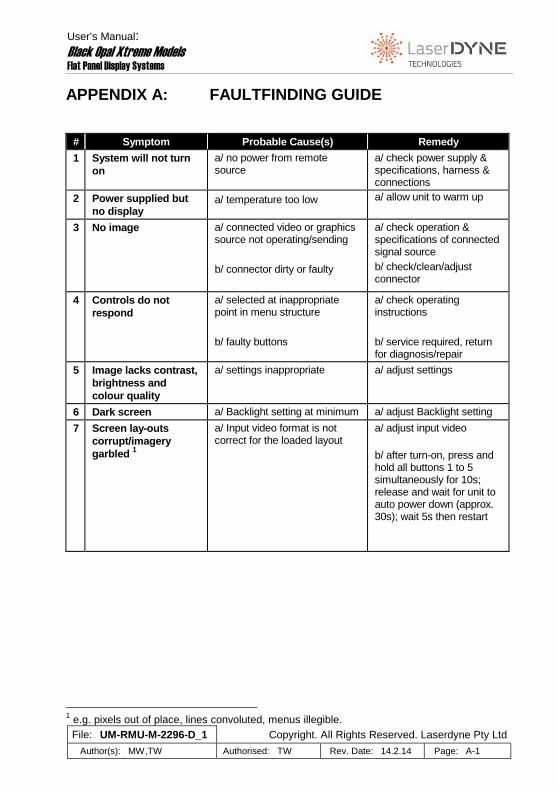
APPENDIX A: FAULTFINDING GUIDE
# Symptom Probable Cause(s) Remedy
1 System will not turn on
a/ no power from remote source
a/ check power supply & specifications, harness & connections
2 Power supplied but no display
a/ temperature too low a/ allow unit to warm up
3 No image a/ connected video or graphics source not operating/sending b/ connector dirty or faulty
a/ check operation & specifications of connected signal source b/ check/clean/adjust connector
4 Controls do not respond
a/ selected at inappropriate point in menu structure b/ faulty buttons
a/ check operating instructions b/ service required, return for diagnosis/repair
5 Image lacks contrast, brightness and colour quality
a/ settings inappropriate a/ adjust settings
6 Dark screen a/ Backlight setting at minimum a/ adjust Backlight setting
7 Screen lay-outs corrupt/imagery garbled 1
a/ Input video format is not correct for the loaded layout
a/ adjust input video b/ after turn-on, press and hold all buttons 1 to 5 simultaneously for 10s; release and wait for unit to auto power down (approx. 30s); wait 5s then restart
1 e.g. pixels out of place, lines convoluted, menus illegible.


User’s Manual: Black Opal Xtreme Models Flat Panel Display Systems
File: UM-RMU-M-2296-D_1 Copyright. All Rights Reserved. Laserdyne Pty Ltd
Author(s): MW,TW Authorised: TW Rev. Date: 14.2.14 Page: B-1
APPENDIX B: SET-UP MENUS
The Xtreme display has two menu structures: the User’s menu structure and the Set-up menu structure. The User’s menu structure is described in the body of this User’s Manual. It allows the operator to perform basic corrections and adjustments effecting the appearance of the display. Any settings made under the User’s menu structure will be retained by the unit and will over-ride the settings made under the Set-up menu structure. The operator can, at any time, return all parameters to the settings selected under the Set-up menu structure. The Set-up menu structure is not used in normal operation. It is only available when a special button combination is activated. It allows basic and advanced set-up of inputs, outputs, corrections and adjustments. The settings selected in the Set-up menu structure become the default settings for parameters in the User’s menu structure. Set-up personnel may, at any time, return all parameters under the Set-up menu structure to the factory default settings. The set-up menu is generally not required by users or installation personnel as the display will be supplied pre-configured to suit the specifics of the intended application. Specifics about accessing the set-up menu are available to approved personnel on request.