ATST TMA Technical Requirements Compliance FAT
36
ATST‐DOC‐21200‐01‐07_Compliance Matrix ATST TMA Technical Requirements Compliance Matrix ‐ FAT According to format specified in the SOW / A4 provisional ‐ Coude OK, mount still to test partial ‐ minor items to correct / non‐compliance or spec relevancy Chapter Spec. 0011 Spec. 0011 Require‐ ment Number Title Description Design Analysis Coude FAT Mount FAT SAT Reference Document (section) Compliant yes no partial Accep‐ tance Compliance / acceptance notes 1.4.1 Common services Comply with SPEC‐0022, ATST Common Services Users Manual TD‐0030: Update of SPEC‐0022‐1/2 Common Services User Manual and Reference Guide to Rev. E ‐ yes Yes 1.4.1 Coordinate System Comply with SPEC‐0027, ATST Coordinate System Definitions, Rev. D ‐ (ATST‐ANA‐22100‐01‐03_ Mount Performance Analysis (section 6), ATST‐ANA‐22200‐01‐02_ Coudé Performance Analysis (section 3)) yes Yes 1.4.1 Optics Comply with SPEC‐0029, ATST Optical Prescription, Rev E ‐ yes Yes 1.4.2 Safety Design, installation and implementation in accordance with SPEC‐0030 C, SPEC‐0031 A, SPEC‐0035 A, SPEC‐0133. TD‐0047: SPEC‐0133 Hazardous Zones Fully Automated Control Access was updated to Rev. B. x x x x ATST‐PLA‐11000‐92/93_ Safety Plan (all sections), ATST‐ANA‐21400‐01‐10_ Hazard Analysis (all sections) see requirement 1.1‐0310 Codes & Regulations for FAT yes Yes see safety punch list for mount ‐ no major issues. Update 20151201 Safety Punchlist factory actions complete 2.1 1.1 ‐0010 TMA‐to‐M1 Assembly Interface is defined in ICD 1.1/1.2, Rev D; Additional considered information: TD‐0024: M1 blower assumptions, TD‐0049: TMA/M1 cell integrated analysis, TD‐0054: M1 cart to floor interface, Data pack for Additional Aperture plate supports, RFW‐0028: M1 attachment point deformation x x x CAD model, Mechanical drawing set, ATST‐REP‐30000‐01‐02_Structural Design Report (section 2), ATST‐ANA‐22100‐02‐02_Strength Analysis (section 6), ATST‐ANA‐22100‐01‐03_Performance Analysis (section 6), ATST‐PLA‐50000‐01‐02_ Factory Acceptance Test Plan (section 7), Site Acceptance Test Plan (section 7) FAT ATST‐PLA‐50002‐01‐02 1 1‐0010 TMA to M1 Assembly IF RFW‐0075_Aperture Plate Mounting Holes yes Yes NC ‐ M1 interface out of position, M1 Aperture plate interface out of position. M1 Cart Hold down bolt patterns out of position Action: Submit re‐alignment plan for M1 interface to be reviewed by AURA prior to action. (complete) ACTION: Correct out of place M1 cart hold down bolt pattern during systems dis‐assembly. Action: AURA reviewing aperture plate non‐compliance. (complete) Update 20150514 IMT submitted the M1 re‐alignment assesment. It shows that the M1 can be moved back into the acceptable tolerance zone with the caveat that the clearance on the M48 bolts/brackets in it's currrent installed position is checked to ensure the lateral movement is possible. Action IMT: lateral Clearance on M48's to be checked during dis‐assembly. ACTION IMT: Correct out of place M1 cart hold down bolt pattern during systems dis‐assembly. Action IMT: submit waiver on the Aperture plate hole positions with the agreed provisions to improve the situation during site assembly as follows: ‐ during dis‐assembly IMT will remake two sets of shims that should reduce the worst pad position (‐y +x location) 4 mm movement in x. ‐ the outer support holes (+y side) will have plug inserts but not drill / tap. Once re‐assembled on site will use the Laser tracker punch nest to set those holes and then drill tap them. ‐ the long + and ‐ x pads are more difficult and there will try during re‐ assembly to use the clearance on the attachment to the OSS to reduce the misalignment. Update 20150624 Verification Method Page 1 of 36
Transcript of ATST TMA Technical Requirements Compliance FAT

ATST‐DOC‐21200‐01‐07_Compliance Matrix
ATST TMA Technical Requirements Compliance Matrix ‐ FATAccording to format specified in the SOW / A4
provisional ‐ Coude OK, mount still to testpartial ‐ minor items to correct / non‐compliance or spec relevancy
ChapterSpec.0011
Spec.0011Require‐ment Number
Title Description
Design
Analysis
Coud
e FA
T
Mou
nt FAT
SAT Reference Document
(section)
Compliant
yesnopartial
Accep‐tance
Compliance / acceptance notes
1.4.1 Common services Comply with SPEC‐0022, ATST Common Services Users Manual
TD‐0030: Update of SPEC‐0022‐1/2 Common Services User Manual andReference Guide to Rev. E
‐ yes Yes
1.4.1 Coordinate System Comply with SPEC‐0027, ATST Coordinate System Definitions, Rev. D
‐(ATST‐ANA‐22100‐01‐03_Mount Performance Analysis (section 6), ATST‐ANA‐22200‐01‐02_Coudé Performance Analysis (section 3))
yes Yes
1.4.1 Optics Comply with SPEC‐0029, ATST Optical Prescription, Rev E
‐ yes Yes
1.4.2 Safety Design, installation and implementation in accordance with SPEC‐0030 C, SPEC‐0031 A, SPEC‐0035 A, SPEC‐0133.
TD‐0047: SPEC‐0133 Hazardous Zones Fully Automated Control Access was updated to Rev. B.
x x x x ATST‐PLA‐11000‐92/93_ Safety Plan (all sections),
ATST‐ANA‐21400‐01‐10_ Hazard Analysis (all sections)
see requirement 1.1‐0310 Codes & Regulations for FAT
yes Yes see safety punch list for mount ‐ no major issues.
Update 20151201Safety Punchlist factory actions complete
2.1 1.1 ‐0010 TMA‐to‐M1 Assembly Interface is defined in ICD 1.1/1.2, Rev D;
Additional considered information:TD‐0024: M1 blower assumptions,TD‐0049: TMA/M1 cell integrated analysis,TD‐0054: M1 cart to floor interface,Data pack for Additional Aperture plate supports,RFW‐0028: M1 attachment point deformation
x x x CAD model,Mechanical drawing set,
ATST‐REP‐30000‐01‐02_Structural Design Report (section 2),ATST‐ANA‐22100‐02‐02_Strength Analysis (section 6),ATST‐ANA‐22100‐01‐03_Performance Analysis (section 6),ATST‐PLA‐50000‐01‐02_ Factory Acceptance Test Plan (section 7),Site Acceptance Test Plan (section 7)
FATATST‐PLA‐50002‐01‐02 1 1‐0010 TMA to M1 Assembly IFRFW‐0075_Aperture Plate Mounting Holes
yes Yes NC ‐ M1 interface out of position, M1 Aperture plate interface out of position. M1 Cart Hold down bolt patterns out of positionAction: Submit re‐alignment plan for M1 interface to be reviewed by AURA prior to action. (complete)ACTION: Correct out of place M1 cart hold down bolt pattern during systems dis‐assembly.Action: AURA reviewing aperture plate non‐compliance. (complete)
Update 20150514IMT submitted the M1 re‐alignment assesment. It shows that the M1 can be moved back into the acceptable tolerance zone with the caveat that the clearance on the M48 bolts/brackets in it's currrent installed position is checked to ensure the lateral movement is possible. Action IMT: lateral Clearance on M48's to be checked during dis‐assembly.ACTION IMT: Correct out of place M1 cart hold down bolt pattern during systems dis‐assembly.Action IMT: submit waiver on the Aperture plate hole positions with the agreed provisions to improve the situation during site assembly as follows:‐ during dis‐assembly IMT will remake two sets of shims that should reduce the worst pad position (‐y +x location) 4 mm movement in x.‐ the outer support holes (+y side) will have plug inserts but not drill / tap. Once re‐assembled on site will use the Laser tracker punch nest to set those holes and then drill tap them. ‐ the long + and ‐ x pads are more difficult and there will try during re‐assembly to use the clearance on the attachment to the OSS to reduce the misalignment.
Update 20150624
Verification Method
Page 1 of 36
ATST‐DOC‐21200‐01‐07_Compliance Matrix
ChapterSpec.0011
Spec.0011Require‐ment Number
Title Description
Design
Analysis
Coud
e FA
T
Mou
nt FAT
SAT Reference Document
(section)
Compliant
yesnopartial
Accep‐tance
Compliance / acceptance notes
2.2 1.1‐0020 TMA‐TO‐TOP END OPTICAL ASSEMBLY
Interface is defined in ICD 1.1/1.3, Rev F, TD‐0050
x x x CAD model,Mechanical drawing set,
ATST‐REP‐30000‐01‐02_Structural Design Report (section 2),ATST‐PLA‐50000‐01‐02_ Factory Acceptance Test Plan (section 7), ATST‐PLA‐80000‐01‐02_ Site Acceptance Test Plan (section 7)
FATATST‐PLA‐50003‐01‐03 1.1‐0020 TMA to TEOA IF
yes yes NC ‐ interface is out by 2mm in Z and 1 mm in X .ACTION: in Z modify shims in disassembly to correct height, in x verify that top OSS tower section can be moved in x on the hole clearance and fix with location pins.NC ‐ not all cable trays installed. Already covered by Cable Wrap procedure.
Update 20151123OSS tower flange through holes increased to 20mm to provide clearance for re‐alignment.The nominal size shims (10mm) were ground down 2mm per the inspection report.Cable trays installed info on tab 2.2
2.3 1.1‐0030 TMA‐TO‐FEED OPTICS Interface is defined in ICD 1.1/1.5, Rev B, RFW‐0011, ATST‐DWG‐00046 Rev C draft
x x x CAD model,Mechanical drawing set,
ATST‐REP‐30000‐01‐02_Structural Design Report (section 2),ATST‐PLA‐50000‐01‐02_ Factory Acceptance Test Plan (section 7), ATST‐PLA‐80000‐01‐02_ Site Acceptance Test Plan (section 7)
FATATST‐PLA‐50004‐01‐03 1.1‐0030 TMA to Feed Optics IFRFW‐0080 M4 Interface Clocking
partial Yes NC ‐ M4 clocking, M5/M6 tower locationACTION: Confirm that M4 clocking re‐alignment is possible during site install. ACTION: Slot holes on m5/m6 tower base to provide alignment adjustment, also include 2 pilot holes for site install location pins.
Update 20151121RFW‐0080_M4 Interface Clocking 20150731 submitted ‐ waiting on CCBM5/M6 tower slotted & pilot holes added ‐ see ATST‐MPR‐11000‐57‐01 Sep Progress meeting & Tab 2.3
Update 20160223RFW‐0080_M4 Interface Clocking Approved & therefore complete.
2.4 1.1‐0040 TMA‐TO‐SYSTEM ALIGNMENT EQUIPMENT
Interface is defined in ICD 1.1/1.7, Rev C
x x x CAD model
ATST‐PLA‐50000‐01‐02_ Factory Acceptance Test Plan (section 7), ATST‐PLA‐80000‐01‐02_ Site Acceptance Test Plan (section 7)
FATATST‐PLA‐50005‐01‐02 1.1‐0040 TMA to System Alignment Equipment IF
partial Yes ISSUE: point 8 on M1 cell periperal blocked by structure, if point moved ‐10mm in Y then is visible.
2.5 1.1‐0050 TMA‐TO‐ACQUISITION TELESCOPE
Interface is defined in ICD 1.1/1.8, Rev C
x x x CAD model,Mechanical drawing set,ATST‐REP‐30000‐01‐02_Structural Design Report (section 2),Factory Acceptance Test Plan (section 7), ATST‐PLA‐80000‐01‐02_ Site Acceptance Test Plan (section 7)
FATATST‐PLA‐50006‐01‐03 1.1‐0050 TMA to Acquisition Telescope IF
partial Yes ISSUE: mounting flange is out of position by 5mm in Z.
Page 2 of 36

ATST‐DOC‐21200‐01‐07_Compliance Matrix
ChapterSpec.0011
Spec.0011Require‐ment Number
Title Description
Design
Analysis
Coud
e FA
T
Mou
nt FAT
SAT Reference Document
(section)
Compliant
yesnopartial
Accep‐tance
Compliance / acceptance notes
2.6 1.1‐0055 TMA TO ADAPTIVE OPTICS M5 ASSEMBLY
Interface is defined in ICD 1.1/2.1, Rev B, ATST‐DWG‐00046 Rev C draft, TD‐0055
x x x CAD model,Mechanical drawing set,ATST‐REP‐30000‐01‐02_Structural Design Report (section 2), Factory Acceptance Test Plan (section 7), ATST‐PLA‐80000‐01‐02_ Site Acceptance Test Plan (section 7)
Yes Yes see feedoptics procedure
2.7 1.1‐0060 TMA‐TO‐COUDÉ STATION Interface is defined in ICD 1.1/3.1.3, Rev E
x x x CAD model,Mechanical drawing set,ATST‐REP‐30000‐01‐02_Structural Design Report (section 3),
FATATST‐PLA‐50008‐01‐01 1.1‐0060 TMA to Coudé Station IF
Yes Yes
2.8 1.1‐0070 TMA‐TO‐ PA&C Interface between Polarimetry Analysis and Calibration System (PA&C) is defined in ICD 1.1/3.1.1, Rev E
x x x CAD model,Mechanical drawing set,ATST‐REP‐30000‐01‐02_Structural Design Report (section 2),ATST‐REP‐30800‐01‐02_Tools and Equipment Report (section 2),Factory Acceptance Test Plan (section 7), ATST‐PLA‐80000‐01‐02_ Site Acceptance Test Plan (section 7)
FATATST‐PLA‐50009‐01‐02 1.1‐0070 TMA to PAandC IFRFW‐0076_GOS Mounting Hole Position
yes Yes NC ‐ the mounting holes are out of tolerance by 2 to 4mm from the Global Cood System. There is a level of uncertainty in the measurements due to measuring with the dummy installed. The MIP showed that the pattern is internally consistent and in‐spec. ACTION: AURA review how critical is the frame location and is the level of misalignment uncertainty acceptable. (complete)ACTION: IMT either re‐measure the interface or IMT submit RFW. TBD after AURA review. (not required)
Update 20150514Action IMT: submit waiver on GOS mounting hole position.
Update 20150624RFW submitted.
Update 20151123RFW‐0076_GOS Mounting Hole Position Approved 31 July 2015.
2.9 1.1‐0080 TMA‐TO‐COUDÉ ENVIRONMENTAL SYSTEM
Interface is defined in ICD 1.1/3.1.5, Rev E
x x x x CAD model,Mechanical drawing set,ATST‐REP‐30000‐01‐02_Structural Design Report (section 3), ATST‐REP‐30000‐11‐03_Mechanical Design Report (section 2),
FATATST‐PLA‐50010‐01‐01 1.1‐0080 TMA to Coudé Env. System IF+N60
Yes Yes Coude Rotator ‐ compliant.Mount ‐ compliant.
Page 3 of 36

ATST‐DOC‐21200‐01‐07_Compliance Matrix
ChapterSpec.0011
Spec.0011Require‐ment Number
Title Description
Design
Analysis
Coud
e FA
T
Mou
nt FAT
SAT Reference Document
(section)
Compliant
yesnopartial
Accep‐tance
Compliance / acceptance notes
2.10 1.1‐0090 TMA‐TO‐TELESCOPE CONTROL SYSTEM
Interface is defined in ICD 1.1/4.4, Rev F
x x x x ATST‐REP‐31600‐01‐01_ATST Software Design Report (all sections),ATST‐PLA‐50000‐01‐02_ Factory Acceptance Test Plan (section 7), ATST‐PLA‐80000‐01‐02_ Site Acceptance Test Plan (section 7)
FATATST‐PLA‐50011‐01‐01 1.1‐0090 TMA to TCS ICD
Yes Yes TMA Software Test Results 20131206
2.11 1.1‐0100 TMA‐TO‐GLOBAL INTERLOCK SYSTEM
Interface is defined in ICD 1.1/4.5, Rev A
x x x x ATST‐REP‐30700‐90‐03_Local Interlock System Design Report (all sections),ATST‐PLA‐50000‐01‐02_ Factory Acceptance Test Plan (section 7), ATST‐PLA‐80000‐01‐02_ Site Acceptance Test Plan (section 7)
FATATST‐PLA‐50012‐01‐01_1.1‐0100 TMA to Global Interlock System ICD 1.1‐4.5 Reference
Yes Yes Coude Rotator (CLIC) ‐ compliantMount (MLIC) ‐ compliant
2.12 1.1‐0110 TMA‐TO‐ENCLOSURE Interface is defined in ICD 1.1/5.0, Rev F
x x x CAD model,Mechanical drawing set,ATST‐REP‐30000‐01‐02_Structural Design Report (section 2), ATST‐PLA‐80000‐01‐02_ Site Acceptance Test Plan (section 7)
FATATST‐PLA‐50007‐01‐02 1.1‐0110 TMA to Enclosure IF
Partial Yes ISSUE: distance for enclosure camera flange to xy plane is 286mm rather than 300mm.
2.13 1.1‐0120 TMA‐TO‐TELESCOPE PIER Interface is defined in ICD 1.1/6.2, Rev G,
RFW‐0029: Mount Allowable Mass
x x x x CAD model,ATST‐DOC‐21100‐02‐01_ Recommendations Pier Design,ATST‐DOC‐21100‐01‐02_ Input to ICD 1.1_6.2,ATST‐DWG‐30913‐00‐01_Pier Interface drawing,
FATATST‐PLA‐50013‐01‐01 1.1‐0120 TMA to Telescope Pier IF
yes Yes Coude Rotator ‐ plate for hard‐stop 30mm low in factory. Mount ‐ PartialNC ‐ IMT need to check the fixator hole locations with LT on dis‐assembly. ACTION: inspect on dis‐assembly.
Update 20151123Inspection details provided 20151014. Fixator holes inspec.Mount ‐ Compliant.
Page 4 of 36

ATST‐DOC‐21200‐01‐07_Compliance Matrix
ChapterSpec.0011
Spec.0011Require‐ment Number
Title Description
Design
Analysis
Coud
e FA
T
Mou
nt FAT
SAT Reference Document
(section)
Compliant
yesnopartial
Accep‐tance
Compliance / acceptance notes
2.14 1.1‐0130 INTERCONNECTS & SERVICES SPECIFICATION
Details are defined in SPEC‐0063, Rev C
x CAD model,Mechanical drawing set,Electrical drawing set,ATST‐LIS‐30600‐01‐10_Cable‐Hoses‐List (all sheets),ATST‐DWG‐30600‐01‐05_TMA Harness Master Diagr. (all sheets),ATST‐REP‐30600‐01‐04_Control System Design Report (all sections),ATST‐LIS‐21300‐20‐12_TMA Power and Torque Budget (sheet "Total")
yes Yes
3.1 1.1‐0140 TRAVEL RANGE Azimuth: travel +/‐ 200 degrees, mid‐point at AZ=110 degrees,Altitude: travel of the OSS shall be 7 degrees < altitude angle < (90 degrees+ 14.04 degrees),Coudé Azimuth: +/‐ 270 degrees
TD‐0036 clarifies the Mount Azimuth and Coude axes Midrange of Travel positions relative to the ATST Coordinate system.
x x x x CAD model,
ATST‐REP‐30600‐01‐04_Control System Design Report (section 4),
FATATST‐PLA‐50014‐01‐02 1.1‐0140 Travel Range
Yes yes Coude Rotator ‐ CompliantMount ‐ Compliant
3.2 1.1‐0150 VELOCITY Azimuth: slewing rates shall be infinitely adjustable from 0 to 2.0 degrees/second,Altitude: slewing rate shall be infinitely adjustable from 0 to 2.0 degree/second,Coudé Azimuth: slewing rate shall be infinitely adjustable from 0 to 6.0 degree/second
x x x x ATST‐REP‐30600‐01‐04_Control System Design Report (section 4),
FATATST‐PLA‐50015‐01‐02 1.1‐0150 Velocity
Yes yes Coude Cable Wrap ‐ compliantCoude Rotator ‐ CompliantMount Azimuth ‐ CompliantMount Altitude ‐ CompliantMount Azimuth Cable Wrap ‐ Compliant
3.3 1.1‐0160 ACCELERATION Azimuth and altitude axes shall have a controlled acceleration rate up to a maximum ± 0.5 degrees/second/second.Coudé structure azimuth axis shall have a controlled acceleration rate up to a maximum ± 0.5 degrees/second/second.
Max. mirror acceleration according to requirements 1.1.1‐0100 and 1.1.3‐0070 shall not be exceeded when using brakes, overtravel stops etc.
x x x x ATST‐REP‐30600‐01‐04_Control System Design Report (section 4),ATST‐ANA‐22100‐02‐02_Strength Analysis (section 6),ATST‐ANA‐22200‐02‐03_Strength Analysis (section 6),ATST‐PLA‐50000‐01‐02_ Factory Acceptance Test Plan (section 7), ATST‐PLA‐80000‐01‐02_ Site Acceptance Test Plan (section 7)
FATATST‐PLA‐50016‐01‐02 1.1‐0160 Acceleration Mount
Yes yes Coude Rotator ‐ CompliantMount Azimuth ‐ CompliantMount Altitude ‐ Compliant
Page 5 of 36

ATST‐DOC‐21200‐01‐07_Compliance Matrix
ChapterSpec.0011
Spec.0011Require‐ment Number
Title Description
Design
Analysis
Coud
e FA
T
Mou
nt FAT
SAT Reference Document
(section)
Compliant
yesnopartial
Accep‐tance
Compliance / acceptance notes
3.4 1.1‐0170 POINTING Pointing anywhere within the specified system travel ranges with a maximum non‐repeatable residual error of 5 arc‐seconds absolute, achievable anytime within six (6) hours of a pointing system calibration. Offset pointing of less than 1 degree with a maximum non‐repeatable residual error of 0.5 arc‐seconds RMS or less pointing anywhere within the specified travel range.
x x x x x ATST‐LIS‐21300‐04‐01_Error Budget (section 4),ATST‐ANA‐22100‐01‐03 Performance Analysis Mount (section 6),ATST‐PLA‐50000‐01‐02_ Factory Acceptance Test Plan (section 7), ATST‐PLA‐80000‐01‐02_ Site Acceptance Test Plan (section 7)
FATATST‐PLA‐50017‐01‐03 2015‐4‐27 1.2‐0170 Pointing
Yes Yes pointing includes the Az foundation sag effect.
3.5 1.1‐0180 TRACKING Drive System Jitter & Stability and Drift requirements (1.1‐0190) to be respected at:• tracking rates from 0 to 0.1 degree/second• tracking accelerations up to 0.1 degree/second/second Additional clarifications: see TD‐0052.
x x x x ATST‐REP‐30600‐03‐01_End‐to‐End Simulation (section 4),ATST‐PLA‐50000‐01‐02_ Factory Acceptance Test Plan (section 7), ATST‐PLA‐80000‐01‐02_ Site Acceptance Test Plan (section 7)
FATATST‐PLA‐50018‐01‐02 1.1‐0180 Tracking
Yes yes
3.6 1.1‐0190 DRIVE SYSTEM JITTER & STABILITY
The Mount drive and servo control system shall exhibit less than 0.075 arc‐seconds RMS jitter.Additional clarifications on wind: see TD‐0022.Clarifications on trajectories: see TD‐0051.
x x x ATST‐REP‐30600‐03‐01_End‐to‐End Simulation (section 4), ATST‐LIS‐21300‐04‐01_Error Budget (section 4),ATST‐PLA‐50000‐01‐02_ Factory Acceptance Test Plan (section 7), ATST‐PLA‐80000‐01‐02_ Site Acceptance Test Plan (section 7)
FATATST‐PLA‐50019‐01‐01D 2.3‐0100 Jitter
Yes yes
3.7 1.1‐0200 DRIFT Drive system shall track with image drift that does not exceed:• 0.05 arc‐seconds during a one (1) minute interval;• 0.1 arc‐seconds during a thirty (30) minute interval; and• 0.3 arc‐seconds during a sixty (60) minute interval.
x x x x ATST‐LIS‐21300‐04‐01_Error Budget (section 4),ATST‐PLA‐50000‐01‐02_ Factory Acceptance Test Plan (section 7), ATST‐PLA‐80000‐01‐02_ Site Acceptance Test Plan(section 7)
FATATST‐PLA‐50020‐01‐03 2015‐06‐20 1.1‐0200‐Drift
Yes Yes
3.8 1.1‐0210 SETTLING TIME Settling time under normal operating conditions shall be 10 seconds from maximum slew speed with maximum deceleration, applicable to all axes simultaneously.See also TD‐0016: Mount 10s, Coudé 18s,RFW_0027: Settling Time
x x x x ATST‐REP‐30600‐03‐01_End‐to‐End Simulation (section 4),ATST‐PLA‐50000‐01‐02_ Factory Acceptance Test Plan (section 7), ATST‐PLA‐80000‐01‐02_ Site Acceptance Test Plan (section 7)
FATATST‐PLA‐50021‐01‐02 1.1‐0210 Settling Time
Yes yes
Page 6 of 36

ATST‐DOC‐21200‐01‐07_Compliance Matrix
ChapterSpec.0011
Spec.0011Require‐ment Number
Title Description
Design
Analysis
Coud
e FA
T
Mou
nt FAT
SAT Reference Document
(section)
Compliant
yesnopartial
Accep‐tance
Compliance / acceptance notes
3.9 1.1‐0220 UNOBSTRUCTED LIGHT PATH The beam envelope dimensional information is provided in SPEC‐0029 ATST Optical Prescription. All TMA hardware must be clear of this beam by a minimum of 20 mm.
x x x x CAD model,
ATST‐PLA‐50000‐01‐02_ Factory Acceptance Test Plan (section 7), ATST‐PLA‐80000‐01‐02_ Site Acceptance Test Plan (section 7)
ATST‐PLA‐50022‐01‐02 1.1‐0220 Unobstructed Light Path
Partial yes Coude Rotator ‐ compliantMount ‐ PartialISSUE: m5/m6 tower requires re‐alignment for interface ‐ Not really an issue for the light path as greater clearance on the beam to hole than the m5/m6 ICD location requirement.
4.1.1 1.1.1‐0010 Mount ‐Payload Major payloads: OSS and Mount BaseDuring Design phase use specified payload masses times 1.1; use of dummy balance weights in design, assembly and tests
x x x CAD model,ATST‐REP‐30000‐01‐02_Structural Design Report (section 2),ATST‐REP‐30800‐01‐02_Tools and Equipment Report (section 2, 3),ATST‐ANA‐22100‐02‐02_Strength Analysis (section 4),ATST‐PLA‐50000‐01‐02_ Factory Acceptance Test Plan (section 7)
FATATST‐PLA‐50023‐01‐03 1.1.1‐0010 Payload (Mount)
Yes yes
4.1.2 1.1.1‐0020 Mount ‐Maximum Allowable Mass
The mass of the mount structure shall not exceed 150 tonnes. This mass shall not include all the payloads specified above in Section 4.1.1.Refer also to: RFW‐0029: Mount Allowable Mass.
x x CAD model,ATST‐LIS‐21300‐01‐05_Mass Budget (sheet "Mount"),ATST‐REP‐30000‐01‐02_Structural Design Report (section 2)
yes Yes spot checks on mass during MIP's were conducted to ensure continued compliance with overall mass budget.
4.1.3 1.1.1‐0030 Mount ‐OSS Assembly Balance About the altitude axis within 200 N‐m; Contractor shall supply any and all required test mass assemblies (dummy weights). To be demonstrated empirically in three discrete positions of the OSS: 90 ‐45 ‐ 15 degrees altitude angle.
x x x CAD model,ATST‐LIS‐21300‐02‐02_Balance Budget + Attachment (section 2.3), ATST‐REP‐30800‐01‐02_Tools and Equipment Report (section 2, 3),ATST‐PLA‐50000‐01‐02_ Factory Acceptance Test Plan (section 7), ATST‐PLA‐80000‐01‐02_ Site Acceptance Test Plan (section 7)
FATATST‐PLA‐50024‐01‐01 1.1.1‐0030 OSS Assembly Balance
Yes yes
4.1.4 1.1.1‐0040 Mount ‐Maximum Volumetric Envelope
The maximum volumetric envelope shall not exceed those dimensions specified in ICD 1.1/5.0, TMA‐to‐Enclosure.
x x CAD model,
ATST‐REP‐30000‐01‐02_Structural Design Report (section 2),ATST‐PLA‐50000‐01‐02_ Factory Acceptance Test Plan (section 7)
FATATST‐PLA‐50025‐01‐02 1.1.1‐0040 Max Volumetric Envelope (Mount)
Yes yes
Page 7 of 36

ATST‐DOC‐21200‐01‐07_Compliance Matrix
ChapterSpec.0011
Spec.0011Require‐ment Number
Title Description
Design
Analysis
Coud
e FA
T
Mou
nt FAT
SAT Reference Document
(section)
Compliant
yesnopartial
Accep‐tance
Compliance / acceptance notes
4.1.5 1.1.1‐0050 Mount ‐Thermal Conditioning of M1
Ventilation aperture in the direction of the x‐axis between the upper bound of the M1 Aperture Plate volume and a level 1m above of equal to or greater than 3 m². The M1 Aperture Plate Volume is defined in ICD 1.1/1.2, TMA‐to‐M 1 Assembly.
x x CAD model
ATST‐PLA‐50000‐01‐02_ Factory Acceptance Test Plan (section 7)
FATATST‐PLA‐50069‐01‐01 1.1.7‐0210 M1 Cover‐Profile
Yes yes
4.1.6 1.1.1‐0060 Mount ‐Minimum Structural Resonance
Minimum Structural Resonance > 8 Hz.
Refer also to: RFW‐0020: Mount Minimum Structural Resonance
x x x FE model,
ATST‐ANA‐22100‐01‐03_Performance Analysis (section 5),ATST‐PLA‐50000‐01‐02_ Factory Acceptance Test Plan (section 7), ATST‐PLA‐80000‐01‐02_ Site Acceptance Test Plan (section 7)
Yes yes The Az axis LRR seems to be lower than FEA predicted but is still close to the RFW minimum freq. Add waiver freq value
4.1.7 1.1.1‐0070 Mount ‐Static Flexure With the full payload as defined in Section 4.1.14.1.1 the mount shall meet the relative interface positioning tolerances specified in Table 1 (< 190/250 µm, < 40/50 µ radians) for M1, TEOA, GOS, M3‐M6.Analysis without soil, with soil for information only.
TD‐0019: The image motion calculation is updated as per TN‐0023 F.
Refer also to: RFW‐0024: Mount Static Flexures
x x FE model,
ATST‐ANA‐22100‐01‐03_Performance Analysis (section 6),ATST‐PLA‐50000‐01‐02_ Factory Acceptance Test Plan (section 7)
FATATST‐PLA‐50028‐01‐05 1 1 1‐0070 Static Flexure MountRFW‐0074_Mount Static Flexure
yes yes Update 20150514NC ‐ some of the flexure / repeatability results are out of specification.
ACTION: IMT to submit an RFW for the out of specification test results.
Update 20150624RFW submitted.
Update 20151123RFW‐0074_Mount Static Flexure approved 20150724
4.1.8 1.1.1‐0080 Mount ‐Wind‐Induced Dynamic Flexure
Nominal 5 m/s time‐varying wind load impinging directly on the mount structure; The calculated maximum image motion at the Coudé focal plane shall not exceed 0.1 arcsec RMS ‐ in three discrete positions of the OSS: 90 ‐45 ‐ 15 degrees altitude angle. More background data are given in:TD‐0005: Wind spectra,TD‐0020: Wind spectra update, TN‐0134 Rev B),TD‐0022: Wind Analysis Clarification.
Refer also to: RFW‐0030: Wind induced dynamic Flexure
x FE model,
ATST‐LIS‐21300‐04‐01_Error Budget (section 4),ATST‐ANA‐22100‐01‐03_Performance Analysis (section 7)
yes Yes
Page 8 of 36

ATST‐DOC‐21200‐01‐07_Compliance Matrix
ChapterSpec.0011
Spec.0011Require‐ment Number
Title Description
Design
Analysis
Coud
e FA
T
Mou
nt FAT
SAT Reference Document
(section)
Compliant
yesnopartial
Accep‐tance
Compliance / acceptance notes
4.1.9 1.1.1‐0090 Enclosure Wind Vibration & Natural Frequency Effects
Dynamic FEA that incorporates a nominal 16m/s time‐varying wind load impinging on a simplified enclosure model shall be analyzed with regard to image motion and TMA natural frequencies.For informational purposes only.
x ‐ yes Yes This analysis effort was deemed less valuable than an analysis of the M1 Cell structure as part of the TMA and as such the scope of work was modified to remove the enclosure analysis and include the M1 cell integrated analysis.
4.1.10 1.1.1‐0100 Mount ‐Seismic Requirements Perform a seismic analysis on the mount structure that determines the levels of stress and strain expected during an earthquake, maximum stresses in the mount structure shall not exceed allowable, safe, and elastic stress levels.The maximum accelerations shall not exceed (horizon and zenith position): 2g for M1, 3g for TEOA 2g for M3‐M6.
Refer also to: RFW‐0023: Seismic accelartion of mirrors
x x FE model,
ATST‐ANA‐22100‐02‐02_Strength Analysis (section 4 ‐ 7)
yes Yes
4.1.11 1.1.1‐0110 Mount ‐Thermal Deflections A thermal deflections analysis shall be performed on the mount structure. This analysis shall demonstrate that maximum allowable optic deflections and displacements specified in Section 4.1.7 are not exceeded under an temperature scenario as specified in TD‐0021.
x FE model,
ATST‐ANA‐22100‐01‐03_Performance Analysis (section 8),ATST‐ANA‐22100‐03‐02_Thermal Analysis (all sections)
yes Yes
Page 9 of 36

ATST‐DOC‐21200‐01‐07_Compliance Matrix
ChapterSpec.0011
Spec.0011Require‐ment Number
Title Description
Design
Analysis
Coud
e FA
T
Mou
nt FAT
SAT Reference Document
(section)
Compliant
yesnopartial
Accep‐tance
Compliance / acceptance notes
4.1.12 1.1.1‐0120 Mount ‐Assembly and Bearing Precision
Maximum azimuth axis run‐out of the mount structure over the full range of azimuth travel (wander from true vertical) shall be +/‐ 10 arc‐seconds or less. Maximum altitude bearing run‐out of the OSS assembly over the full range of travel of altitude (wander from true horizontal) shall be +/‐ 5 arc‐seconds or less (SPEC‐0011). As per clarification in TD‐0010: This maximum altitude bearing run‐out shall be measured from the perpendicular to the measured Telescope mount Azimuth datum axis.
Maximum perpendicularity error of the azimuth and altitude axes over the full ranges of their travel shall be +/‐ 10 arc‐seconds or less. The mount structure azimuth axis shall be capable of adjustment and alignment during installation (i.e., coaxial adjustment) to the Coudé rotator azimuth axis to within +/‐ 0.25 mm. The range of travel of this adjustment shall be +/‐25.0 mm.
x x x x ATST‐SPE‐30000‐03‐02_Trucks and Rails Spec (section 4),ATST‐PLA‐50000‐01‐02_ Factory Acceptance Test Plan (section 7), ATST‐PLA‐80000‐01‐02_ Site Acceptance Test Plan (section 7)
Yes yes Coude Rotator ‐ compliantMount ‐ compliant
4.2.1 1.1.1‐0130 Mount Structure Azimuth and Altitude Bearing
Bearings shall be sufficiently stiff and friction free, be of high reliability design and shall require minimal maintenance over the lifetime, allow easy maintenance, lubrication, inspection, and removal and replacement (replaceable within a 24‐hour period by no more than two observatory technicians with standard skills and training).Any pumping & filtration system used for the bearings shall be fully redundant. Bearings shall be fitted with covers, seals, drains, and wipers to eliminate any external contamination, out‐gassing, and/or leakage. If an azimuth track/rail is used, it shall be fitted with a steel cover that extends down from the bottom of the mount base structure and protects the track surfaces from falling objects and personnel. The covers shall be able to be partially disassembled for access to the track during maintenance operations.
x x x CAD model,
ATST‐REP‐30000‐11‐03_Mechanical Design Report, (section 2, 3), ATST‐REP‐30000‐90‐01_Test Stand for Az/Coudé Bearing System (all sections),ATST‐SPE‐30000‐02‐02_ALT‐Bearing (all sections),ATST‐SPE‐30000‐03‐02_Trucks and Rails Spec (all sections),ATST‐REP‐22100‐01‐01_ Executive Summary of Friction and Jitter Tests (all sections),ATST‐PLA‐50000‐01‐02_ Factory Acceptance Test Plan (section 7)
FATATST‐PLA‐50030‐01‐01 1.1.1‐0130 Mount Structure Azimuth and Alt Bearing
Yes yes
Page 10 of 36
ATST‐DOC‐21200‐01‐07_Compliance Matrix
ChapterSpec.0011
Spec.0011Require‐ment Number
Title Description
Design
Analysis
Coud
e FA
T
Mou
nt FAT
SAT Reference Document
(section)
Compliant
yesnopartial
Accep‐tance
Compliance / acceptance notes
4.2.2 1.1.1‐0140 Mount Structure Personnel & Equipment Access
All access stairs, platforms, and entrance points for maintenance inside and around the mount structure shall be provided by Contractor. All access platforms and light flooring, unless specified otherwise, shall be designed to accommodate up to a 1000 kg live load distributed over a maximum square area of 300mm x 300mm that is located anywhere on its working surface. The TMA Telescope Level Floor shall be designed to allow use of a lift Truck of nominal 3300kg capacity such as CAT Lift truck model 2C6500.The platform load are clarified in TD‐0026: of 488 kg/m^2 (100 psf).
x x CAD model,
ATST‐REP‐30000‐01‐02_Structural Design Report (section 2), ATST‐ANA‐22100‐02‐02_Strength Analysis (section 6),ATST‐PLA‐50000‐01‐02_ Factory Acceptance Test Plan (section 7)
FATATST‐PLA‐50031‐01‐02 1.1.1‐0140 Mount Structure Personnel and Equipment Access
yes Yes NC ‐ seal / alt access hand rail / toeboardsthese items are covered under the Utility seal procedure in cable wrap section and others covered in safety punch list.
Update 20151123Marked as compliant and accepted based on covered by safety punchlist.
4.2.3 1.1.1‐0150 Mount ‐Thermal Control Features
The OSS and mount base assembly shall be designed in such a way as to allow air to be drawn down through the structural elements and exhausted below the telescope floor level. The system of fans and equipment used to ventilate this air is not included in this Contract, but the implementation of thru‐holes in the bulkheads, hollow members, and mechanical joints that allow air to pass through is included in the Contract.The M5‐M6 tower should have vent holes. An Air Knife interface according to ICD 1.1/3.1.5 has to be respected.
x x CAD model,
ATST‐REP‐30000‐01‐02_Structural Design Report (section 2), ATST‐REP‐30000‐11‐03_Mechanical Design Report (section 2),ATST‐PLA‐50000‐01‐02_ Factory Acceptance Test Plan (section 7)
FATATST‐PLA‐50032‐01‐01 1.1.1‐0150 OSS Thermal Control Features
Yes yes
4.2.4 1.1.1‐0160 Mount ‐Nasmyth Upgrade Features
The altitude bearing trunnions (and supporting OSS structure) shall have a free and unobstructed central bore (i.e., inner diameter) equal to no less than 800mm. Nasmyth rotator: 2m diameter instrument, 5 tonnes loads, 20 kNm on the bearing trunnions with less than 200 µm of deflection in z and y. 3 tonnes on Nasmyth platform, which is located min. 1200 mm below the Alt axis on both sides of the OSS. Enough space for the Nasmyth instruments has to be foreseen.
x x x CAD model,
ATST‐ANA‐22100‐01‐03_Performance Analysis (section 10), ATST‐REP‐30000‐01‐02_Structural Design Report (section 2), ATST‐PLA‐50000‐01‐02_ Factory Acceptance Test Plan (section 7)
FATATST‐PLA‐50033‐01‐01 1.1.1‐0160 Nasmyth Upgrade Feature
yes Yes NC ‐ structural support for the Instrument fab'd in place and then removed prior to fitting the pipe manifold. The manifold and structure will be close so fit check is required.ACTION: during dis‐assembly fit Nasymth instrument support structure prior to manifold removal.
Update 20151123see ATST‐MPR‐11000‐57‐01 Sept 2015 Progress Report & tabe 4.2.4 for check as requested. No clash
Page 11 of 36

ATST‐DOC‐21200‐01‐07_Compliance Matrix
ChapterSpec.0011
Spec.0011Require‐ment Number
Title Description
Design
Analysis
Coud
e FA
T
Mou
nt FAT
SAT Reference Document
(section)
Compliant
yesnopartial
Accep‐tance
Compliance / acceptance notes
5.1.1 1.1.3‐0010 Coude ‐ Size Floor diameter 16.5 meters, lower work space that is 6m × 6m × 2.3m high.
x x CAD model,Mechanical drawing set,
ATST‐REP‐30000‐01‐02_Structural Design Report (section 3),
FATATST‐PLA‐50034‐01‐01 1.1.3‐0010 Coudé Size
Yes yes
5.1.2 1.1.3‐0020 Coude ‐ Payload Mounting surfaces and interfaces for the following major payloads: M7 through BS1 Assemblies, Stations for Instruments, Station for Wavefront (as specified in their respective ICDs). The payload sizes and masses as per ICDs have to considered in the analysis/design.
x x x CAD model,Mechanical drawing set,ATST‐REP‐30000‐01‐02_Structural Design Report (section 3),ATST‐ANA‐22200‐02‐03_Strength Analysis (section 4)
FAT ‐ covered by req 1.1‐0060ATST‐PLA‐50008‐01‐01 1.1‐0060 TMA to Coudé Station IF
Yes yes
5.1.3 1.1.3‐0030 Coude ‐ Maximum Allowable Mass
The maximum mass shall not exceed 100 tonnes (not include the payloads).
Refer also to: RFW‐0022: Coudé Allowable Mass
x x CAD model,ATST‐LIS‐21300‐01‐05_Mass Budget (sheet "Coudé"),ATST‐REP‐30000‐01‐02_Structural Design Report (section 3)
yes yes
5.1.4 1.1.3‐0040 Coude ‐ Maximum Volumetric Envelope
Not exceed those dimensions specified in ICD 1.1/6.2, TMA‐to‐Building.
x x CAD model,
ATST‐REP‐30000‐01‐02_Structural Design Report (section 3),
FAT ‐ covered by req 1.1‐0080ATST‐PLA‐50010‐01‐01 1.1‐0080 TMA to Coudé Env. System IF
Yes yes
5.1.5 1.1.3‐0050 Coude ‐ Minimum Structural Resonance
The minimum natural frequency shall not be less than 10 Hz (TBR) with payloads.Analysis without soil, with soil for information only.
Refer also to: RFW‐0021: Coudé Minimum Structural Resonance
x FE model,
ATST‐ANA‐22200‐01‐02_Performance Analysis (section 4)
yes yes
Page 12 of 36

ATST‐DOC‐21200‐01‐07_Compliance Matrix
ChapterSpec.0011
Spec.0011Require‐ment Number
Title Description
Design
Analysis
Coud
e FA
T
Mou
nt FAT
SAT Reference Document
(section)
Compliant
yesnopartial
Accep‐tance
Compliance / acceptance notes
5.1.6 1.1.3‐0060 Coude ‐ Static Flexure Shall be sufficiently stiff that, with the full payload as defined in Section 5.1.2, it shall meet the optics positioning tolerances specified in Table (displacements < 50‐100 µm and rotations 10‐40 µrad in X, Y, Z).The static flexure under one persons' weight shall be < 20 µm, 1.5E5 µrad.The static flexure under changed instrument scenarios shall be < 400 µm, 100 µrad.Analysis without soil, with soil for information only.
x x x FE model,
ATST‐ANA‐22200‐01‐02_Performance Analysis (section 4),ATST‐PLA‐50000‐01‐02_ Factory Acceptance Test Plan (section 7)
Yes yes the match between the FEA and the measured deflections showed significant variance in some cases. These variances were attributed to:1) the stability of the temporary fixtures used for the target locations.2) the stability of the foundation and floor in the factory which was shown to have significant movement both through direct measurement and checks on the reference targets.3) the accuracy & stability of the laser tracker used. For further details on results and discussion refer to the signed procedure.
5.1.7 1.1.3‐0070 Coude ‐ Seismic Requirements Under the highest expected seismic loading per IBC guidelines, the maximum acceleration of the M7 through BS1 assemblies and the Coudé Stations mounted onto the Coudé Structure does not exceed 2.0 times the acceleration due to gravity in any direction.
x x FE model,
ATST‐ANA‐22200‐02‐03_Strength Analysis (section 6)
yes yes
5.1.8 1.1.3‐0080 Coude ‐ Thermal Deflections Demonstrate that maximum allowable optic deflections and displacements specified in Section 5.1.6, are not exceeded under an temperature scenario as specified in TD‐0021.
x x FE model,
ATST‐ANA‐22200‐03‐02_Thermal Analysis (all sections)
yes yes
5.1.9 1.1.3‐0090 Coude ‐ Assembly and Bearing Precision
Azimuth axis run‐out of the Coudé rotator structure over the full range of azimuth travel (wander from true vertical) shall be less than or equal to +/‐ 10 arc‐seconds
x x x ATST‐SPE‐30000‐03‐02_Trucks and Rails Spec (section 4),
FAT ‐ covered under procedure for 1.1‐0120ATST‐PLA‐50029‐01‐02 1.1.1‐0120 Assembly and Bearing Precision
Yes yes
5.2.1 1.1.3‐0100 Coudé Rotator Structure Bearing
The bearing system shall be identical to those of the mount structure azimuth bearing and shall be fitted with a radial centering bearing that can be manually adjusted to meet the azimuth axis coaxial requirements.TD‐0009 includes clarifications on the Coudé Rotator bearing centering in case the thrust and radial bearing functions are combined in the same bearing implementation.
x x x CAD model,ATST‐REP‐30000‐11‐03_Mechanical Design Report (section 2, 3),
FAT ‐ covered under procedure for 1.1‐0120ATST‐PLA‐50029‐01‐02 1.1.1‐0120 Assembly and Bearing Precision
Yes yes
Page 13 of 36
ATST‐DOC‐21200‐01‐07_Compliance Matrix
ChapterSpec.0011
Spec.0011Require‐ment Number
Title Description
Design
Analysis
Coud
e FA
T
Mou
nt FAT
SAT Reference Document
(section)
Compliant
yesnopartial
Accep‐tance
Compliance / acceptance notes
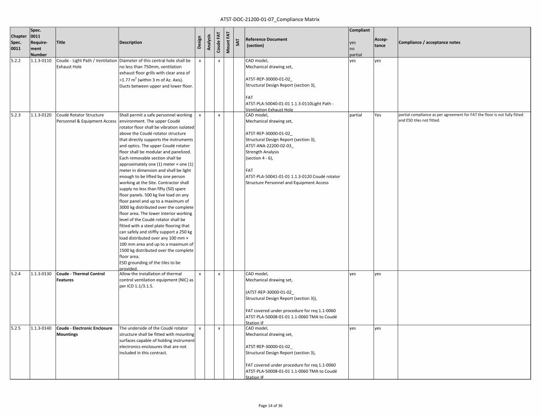
5.2.2 1.1.3‐0110 Coude ‐ Light Path / Ventilation Exhaust Hole
Diameter of this central hole shall be no less than 750mm, ventilation exhaust floor grills with clear area of >1.77 m2 (within 3 m of Az. Axis). Ducts between upper and lower floor.
x x CAD model,Mechanical drawing set,
ATST‐REP‐30000‐01‐02_Structural Design Report (section 3),
FATATST‐PLA‐50040‐01‐01 1.1.3‐0110Light Path ‐ Ventilation Exhaust Hole
yes yes
5.2.3 1.1.3‐0120 Coudé Rotator Structure Personnel & Equipment Access
Shall permit a safe personnel working environment. The upper Coudé rotator floor shall be vibration isolated above the Coudé rotator structure that directly supports the instruments and optics. The upper Coudé rotator floor shall be modular and panelized. Each removable section shall be approximately one (1) meter × one (1) meter in dimension and shall be light enough to be lifted by one person working at the Site. Contractor shall supply no less than fifty (50) spare floor panels. 500 kg live load on any floor panel and up to a maximum of 3000 kg distributed over the complete floor area. The lower interior working level of the Coudé rotator shall be fitted with a steel plate flooring that can safely and stiffly support a 250 kg load distributed over any 100 mm × 100 mm area and up to a maximum of 1500 kg distributed over the complete floor area. ESD grounding of the tiles to be provided.
x x CAD model,Mechanical drawing set,
ATST‐REP‐30000‐01‐02_Structural Design Report (section 3),ATST‐ANA‐22200‐02‐03_Strength Analysis (section 4 ‐ 6),
FATATST‐PLA‐50041‐01‐01 1.1.3‐0120 Coudé rotator Structure Personnel and Equipment Access
partial Yes partial compliance as per agreement for FAT the floor is not fully fitted and ESD tiles not fitted.
5.2.4 1.1.3‐0130 Coude ‐ Thermal Control Features
Allow the installation of thermal control ventilation equipment (NIC) as per ICD 1.1/3.1.5.
x x CAD model,Mechanical drawing set,
(ATST‐REP‐30000‐01‐02_Structural Design Report (section 3)),
FAT covered under procedure for req 1.1‐0060ATST‐PLA‐50008‐01‐01 1.1‐0060 TMA to Coudé Station IF
yes yes
5.2.5 1.1.3‐0140 Coude ‐ Electronic Enclosure Mountings
The underside of the Coudé rotator structure shall be fitted with mounting surfaces capable of holding instrument electronics enclosures that are not included in this contract.
x x CAD model,Mechanical drawing set,
ATST‐REP‐30000‐01‐02_Structural Design Report (section 3),
FAT covered under procedure for req 1.1‐0060ATST‐PLA‐50008‐01‐01 1.1‐0060 TMA to Coudé Station IF
yes yes
Page 14 of 36

ATST‐DOC‐21200‐01‐07_Compliance Matrix
ChapterSpec.0011
Spec.0011Require‐ment Number
Title Description
Design
Analysis
Coud
e FA
T
Mou
nt FAT
SAT Reference Document
(section)
Compliant
yesnopartial
Accep‐tance
Compliance / acceptance notes
5.2.6 1.1.3‐0150 Coude ‐ Instrument Support Beams
Contractor shall provide twenty‐six (26) instrument support beam (ISB) assemblies, each ISB shall be design to stiffly carry the loads imparted by a fully loaded instrument optics bench, as defined in ICD 1.1/3.1.3 TMA‐to‐Coudé Station.
x x CAD model,Mechanical drawing set,
ATST‐REP‐30000‐11‐03_Mechanical Design Report (section 4),
FATATST‐PLA‐50044‐01‐01 1.1.3‐0150 Instrument Support Beams
yes yes
6.1 1.1‐0230 TRAVEL RANGE LIMITS Axes shall each include a minimum of four levels of travel range limit protection as follows: Soft Limit, End of Travel Limit, Final Limit, Hard Limit. (fail safe)
x x x x ATST‐REP‐30600‐01‐04_Control System Design Report (section 4),ATST‐PLA‐50000‐01‐02_ Factory Acceptance Test Plan (section 7), ATST‐PLA‐80000‐01‐02_ Site Acceptance Test Plan (section 7)
FATATST‐PLA‐50045‐01‐04 1.1‐0230 Travel Range Limits
Yes yes Coude Rotator ‐ compliantMount ‐ compliant
6.2 1.1‐0240 ENCODER The encoders shall have a resolution of at least 0.02 arc‐seconds and shall provide both incremental and absolute position information to the mount control system. If a tape encoder is employed on the mount azimuth or Coudé azimuth axis, at least four independent read heads shall be installed and utilized in determination of axis position.If a tape encoder is employed on the altitude axis, at least one read head shall be used per tape and a minimum of two encoder tapes shall be employed (e.g., one on each altitude disk).
x x x ATST‐REP‐30600‐01‐04_Control System Design Report, (section 4),ATST‐SPE‐30000‐05‐06_Encoder Spec (all sections),ATST‐PLA‐50000‐01‐02_ Factory Acceptance Test Plan (section 7)
FATATST‐PLA‐50046‐01‐01 1.1‐0240 Encoder
Yes yes
6.3 1.1‐0250 OVER‐SPEED SENSING The Over‐speed sensing shall disengage the drive system for its particular axis and shall engage the brakes in the event that speeds 25 percent greater than maximum specified are detected.
x x x ATST‐REP‐30600‐01‐04_Control System Design Report
FATATST‐PLA‐50047‐01‐01_1.1‐0250 Over‐Speed Sensing
Yes yes Coude Rotator ‐ CompliantMount Azimuth ‐ CompliantMount Altitude ‐ Compliant
Page 15 of 36

ATST‐DOC‐21200‐01‐07_Compliance Matrix
ChapterSpec.0011
Spec.0011Require‐ment Number
Title Description
Design
Analysis
Coud
e FA
T
Mou
nt FAT
SAT Reference Document
(section)
Compliant
yesnopartial
Accep‐tance
Compliance / acceptance notes
6.4 1.1‐0260 BRAKING On all rotational axes with the use of fail‐safe brakes whenever electrical power is removed, stopping the rotation of any axis within two (2) seconds from the maximum slew speed.
x x x ATST‐REP‐30600‐01‐04_Control System Design Report (section 4),ATST‐REP‐30000‐11‐03_Mechanical Design Report (section 2, 3),ATST‐SPE‐30000‐07‐04_Brakes Spec (all sections),ATST‐SPE‐30000‐13‐04_Alt. Brakes Spec (all sections),ATST‐PLA‐50000‐01‐02_ Factory Acceptance Test Plan (section 7)
FATATST‐PLA‐50048‐01‐02 1.1‐0260 Braking
Yes yes Coude Rotator ‐ CompliantMount Azimuth ‐ CompliantMount Altitude ‐ Compliant
6.5 1.1‐0270 DRIVE TORQUE A margin of 2.2 over the maximum nominal torque has to be applied in the dimensioning.
x x ATST‐LIS‐21300‐20‐12_TMA Power and Torque Budget (sheet "torque calc")
yes yes
6.6 1.1‐0280 MANUAL DRIVE SYSTEM The manual drive system shall be capable of rotating the OSS in altitude over its full range of travel with up to 0.5 degrees per second.
x x CAD model,
ATST‐REP‐30000‐11‐03_Mechanical Design Report (section 2),ATST‐PLA‐50000‐01‐02_ Factory Acceptance Test Plan (section 7)
FATATST‐PLA‐50049‐01‐01 1.1‐0280 Manual Drive System
Yes yes
6.7 1.1‐0290 SERVO SYSTEMS The servo systems employed as part of the drive system shall be designed in such a manner as to facilitate testing & maintenance, as well as the normal operational configuration.
x x x ATST‐REP‐30600‐01‐04_Control System Design Report (all sections),ATST‐PLA‐50000‐01‐02_ Factory Acceptance Test Plan (section 7)
FATATST‐PLA‐50050‐01‐01 1.1‐0290 Servo Systems
Yes Yes NC ‐ Beckhoff code uses German commenting / variables.ACTION: laid out in the procedure and agreed with MTM to include additional English commentary / outlines and variable glossary. Also provision of servo tuning scripts used during system tuning in Rockford.
Update 20160223See email review by JH & BMcB ‐ 20160223 JH & BMcB review of CMCS software with English Commentary. Now deemed compliant & Accepted.
7.1.1 1.1.7‐0010 LOCKING PINS ‐ General The OSS shall each be fitted with locking pins that fully restrain rotation.
x x x CAD model,Mechanical drawing set,
ATST‐REP‐30000‐11‐03_Mechanical Design Report (section 4),ATST‐PLA‐50000‐01‐02_ Factory Acceptance Test Plan (section 7)
FATATST‐PLA‐50051‐01‐01 1.1.7‐0010 Locking Pin‐General
Yes yes
Page 16 of 36

ATST‐DOC‐21200‐01‐07_Compliance Matrix
ChapterSpec.0011
Spec.0011Require‐ment Number
Title Description
Design
Analysis
Coud
e FA
T
Mou
nt FAT
SAT Reference Document
(section)
Compliant
yesnopartial
Accep‐tance
Compliance / acceptance notes
7.1.2 1.1.7‐0020 LOCKING PINS ‐ Operation All locking pins shall be manually deployed (i.e., inserted) and manually retracted (i.e., stowed).
x x CAD model,
ATST‐REP‐30000‐11‐03_Mechanical Design Report (section 4),ATST‐PLA‐50000‐01‐02_ Factory Acceptance Test Plan (section 7)
FATATST‐PLA‐50052‐01‐01 1.1.7‐0020 Locking Pin‐Operation
yes Yes NC ‐ Indexing pin does not fully engage on ‐X side ‐ expected galling of pin end. ACTION: repair on dis‐assembly and track through the punch list.
Update 20151123complete see punchlist
7.1.3 1.1.7‐0030 LOCKING PINS ‐ Insertion Position
Shall have three distinct insertion positions: Fully retracted, intermediate test position, fully deployed.
x x CAD model,
ATST‐REP‐30000‐11‐03_Mechanical Design Report (section 4),ATST‐PLA‐50000‐01‐02_ Factory Acceptance Test Plan (section 7)
FATATST‐PLA‐50053‐01‐01 1.1.7‐0030 Locking Pin‐Insertion Position
Yes yes
7.1.4 1.1.7‐0040 LOCKING PINS ‐ Limit Switches Locking pins shall be fitted with electrical signal‐switch devices.
x x x ATST‐REP‐30600‐01‐04_Control System Design Report (section 4),ATST‐SPE‐30000‐11_ TMA Requirements to LIC (section 3),ATST‐PLA‐50000‐01‐02_ Factory Acceptance Test Plan (section 7), ATST‐PLA‐80000‐01‐02_ Site Acceptance Test Plan (section 7)
FATATST‐PLA‐50054‐01‐01 1.1.7‐0040 Locking Pin Limit Switches
Yes yes
7.1.5 1.1.7‐0050 LOCKING PINS ‐ Design Load and Factor of Safety
Designed with a minimum factor of safety of 5.0 as per SPEC‐0011. The factor of safety is detailed for operational and seismic loads in TD‐0038.
x x ATST‐ANA‐22100‐02‐02_Strength Analysis (section 6)
yes yes
7.1.6 1.1.7‐0060 LOCKING PINS ‐ OSS Locked Positions
Shall be designed to accommodate the individual removal of any of the OSS‐mounted payloads, e.g. M1 in zenith position, TEOA in horizon position).The locked positions shall be adjustable within ± one (1) degree.
x x CAD model, FE model,Mechanical drawing set,
ATST‐ANA‐22100‐02‐02_Strength Analysis (section 6), ATST‐REP‐30000‐11‐03_Mechanical Design Report (section 4),ATST‐PLA‐50000‐01‐02_ Factory Acceptance Test Plan (section 7)
FATATST‐PLA‐50055‐01‐02 1.1.7‐0060 OSS Locked Positions
Yes yes
Page 17 of 36

ATST‐DOC‐21200‐01‐07_Compliance Matrix
ChapterSpec.0011
Spec.0011Require‐ment Number
Title Description
Design
Analysis
Coud
e FA
T
Mou
nt FAT
SAT Reference Document
(section)
Compliant
yesnopartial
Accep‐tance
Compliance / acceptance notes
7.2.1 1.1.7‐0070 OSS BALANCE SYSTEM ‐ General
The final balance of the OSS assembly shall be achieved via a series of steel weight plates that can be easily added or removed from the OSS to achieve balance about the altitude axis.
x x CAD model,Mechanical drawing set,
ATST‐REP‐30000‐11‐03_Mechanical Design Report (section 4),ATST‐LIS‐21300‐02‐02_ Balance Budget (all sheets plus attachment),ATST‐PLA‐50000‐01‐02_ Factory Acceptance Test Plan (section 7)
FATATST‐PLA‐50056‐01‐01 1.1.7‐0070 OSS Balance System ‐ General
Yes yes
7.2.2 1.1.7‐0080 OSS BALANCE SYSTEM ‐ Size and Resolution
The maximum expected imbalance that the counter‐balance system shall be capable of counteracting is ±4000 kg‐m along the Y‐axis and ±1000kg‐m along the Z‐axis. The resolution of the counter‐balance system shall be 10 kg‐m in both the Y‐ and Z‐directions.
x x CAD model,Mechanical drawing set,
ATST‐REP‐30000‐11‐03_Mechanical Design Report (section 4),ATST‐LIS‐21300‐02‐02_ Balance Budget (all sheets plus attachment),ATST‐PLA‐50000‐01‐02_ Factory Acceptance Test Plan (section 7)
FATATST‐PLA‐50057‐01‐02 1.1.7‐0080 OSS Balance System ‐ Size and Resolution
Yes yes
7.2.3 1.1.7‐0090 OSS BALANCE SYSTEM ‐ Handling Considerations
Shall not weigh more than can be reasonably handled by a typical observatory worker.
x x CAD model,Mechanical drawing set,
ATST‐REP‐30000‐11‐03_Mechanical Design Report (section 4),ATST‐PLA‐50000‐01‐02_ Factory Acceptance Test Plan (section 7)
FATATST‐PLA‐50058‐01‐01 1.1.7‐0090 OSS Balance System ‐ Handling
Yes yes NC ‐ weight plates not marked as per spec.ACTION: during dis‐assembly weight plates to be marked with weight and type.
Update 20151123Complete as per punch list & see tab 7.2.3
7.2.4 1.1.7‐0100 OSS BALANCE SYSTEM ‐ Workmanship
Fabricated and finished to the same professional standards.
x x ATST‐REP‐30000‐11‐03_Mechanical Design Report (section 4),ATST‐SPE‐30000‐01‐03_Steel Structure Specification(sections 1, 8)
FATATST‐PLA‐50059‐01‐01 1.1.7‐0100 OSS Balance System ‐ Workmanship
Yes yes
Page 18 of 36
ATST‐DOC‐21200‐01‐07_Compliance Matrix
ChapterSpec.0011
Spec.0011Require‐ment Number
Title Description
Design
Analysis
Coud
e FA
T
Mou
nt FAT
SAT Reference Document
(section)
Compliant
yesnopartial
Accep‐tance
Compliance / acceptance notes
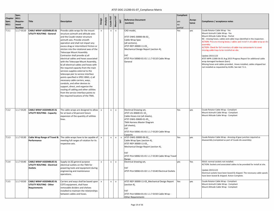
7.3.1 1.1.7‐0110 CABLE WRAP ASSEMBLIES & UTILITY ROUTING ‐ General
Provide cable wraps for the mount structure azimuth and altitude axes and the Coudé rotator structure azimuth axis. Provide smooth operation and shall not impart any excess drag or intermittent friction or stiction into the rotational axes of the Telescope Mount Assembly. Contractor shall provide a) all electrical cables and hoses associated with the Telescope Mount Assembly, b) all electrical cables and hoses with the required capacity from the main services supplies external to the telescope pier to service interface points specified in SPEC‐0063, c) all necessary cable carriers, ways, conduits, and other devices to support, direct, and organize the routing of cabling and other utilities from the service interface points to the required locations of the TMA.
x x x CAD model,
ATST‐DWG‐30000‐06‐02_Cable Wrap Spec(all sections),ATST‐REP‐30000‐11‐03_Mechanical Design Report (section 4),
FATATST‐PLA‐50060‐01‐01 1.1.7‐0110 Cable Wrap General
Yes yes Coude Rotator Cable Wrap ‐ YesMount Azimuth Cable Wrap ‐ YesMount Altitude Cable Wrap ‐ PartialNC ‐ missing hoses, cables and cable trays identified in the inspection.ACTION: Procure missing hoses / cables and install in alt cable wrap on dis‐assembly. ACTION: Check for full inventory of cable tray components to cover missing cable trays to be installed on site.
Update 20151123ATST‐MPR‐11000‐56‐01 Aug 2015 Progress Report for additional cable wrap damaged hardware (bars)MIssing hoses and cables provided . Hoses installed, cables shipped but not installed as requested by AURA. See tab 7.3.1.
7.3.2 1.1.7‐0120 CABLE WRAP ASSEMBLIES & UTILITY ROUTING ‐ Capacity
The cable wraps are designed to allow for at least a 50‐percent future expansion of the quantity of utilities lines.
x x x Electircal Drawing set,ATST‐LIS‐30600‐01‐10_Cable‐Hoses‐List (all sheets),ATST‐DWG‐30600‐01‐05_TMA Harness Master Diagram(all sheets),FATATST‐PLA‐50061‐01‐01 1.1.7‐0120 Cable Wrap Capacity
Yes yes Coude Rotator Cable Wrap ‐ CompliantMount Azimuth Cable Wrap ‐ CompliantMount Altitude Cable Wrap ‐ Compliant
7.3.3 1.1.7‐0130 Cable Wrap Range of Travel & Performance
The cable wraps have to be capable of meeting full ranges of rotation for its respective axis.
x x x x ATST‐DWG‐30000‐06‐02_Cable Wrap Spec (section 4),ATST‐REP‐30000‐11‐03_Mechanical Design Report (section 4),
FATATST‐PLA‐50062‐01‐01 1.1.7‐0130 Cable Wrap Travel Range
Yes yes Coude Rotator Cable Wrap ‐ dressing of gear junction required as disassembly (completed as part of Coude dis‐assembly).
7.3.4 1.1.7‐0140 CABLE WRAP ASSEMBLIES & UTILITY ROUTING ‐ Electrical Outlets
Supply six (6) general purpose electrical outlets on the TMA for powering tools and equipment during engineering and maintenance operations.
x x x Electrical drawing set,
FATATST‐PLA‐50063‐01‐02 1.1.7‐0140 Electrical Outlets
yes Yes ISSUE: normal sockets not installed. ACTION: Sockets and associated cables to be provided for install at site.
Update 20151123Electrical sockets have been boxed & shipped. The necessary cable spools have been boxed & shipped. Action Complete.
7.3.5 1.1.7‐0150 CABLE WRAP ASSEMBLIES & UTILITY ROUTING ‐ Other Requirements
Carriers and ways shall be based upon COTS equipment, shall have removable dividers and shelves installed to maintain the relationships between cables and hoses.
x x x ATST‐REP‐30000‐11‐03_Mechanical Design Report (section 4),
FATATST‐PLA‐50064‐01‐01 1.1.7‐0150 Cable Wrap ‐ Other Requirements
Yes yes Coude Rotator Cable Wrap ‐ CompliantMount Azimuth Cable Wrap ‐ CompliantMount Altitude Cable Wrap ‐ Compliant
Page 19 of 36

ATST‐DOC‐21200‐01‐07_Compliance Matrix
ChapterSpec.0011
Spec.0011Require‐ment Number
Title Description
Design
Analysis
Coud
e FA
T
Mou
nt FAT
SAT Reference Document
(section)
Compliant
yesnopartial
Accep‐tance
Compliance / acceptance notes
7.4.1 1.1.7‐0160 MIRROR COVER ASSEMBLY ‐ General
The M1 cover shall completely cover and protect the M1 Assembly from falling objects when closed and when open shall not vignette or otherwise obscure the light path from the Sun to the M1 assembly or from the M1 assembly to the M2 assembly.
TD‐0029 includes M1 Cover Clarifications for requirements in SPEC‐0011.
x x ATST‐REP‐30000‐11‐03_Mechanical Design Report (section 4),ATST‐SPE‐30000‐12‐04_Mirror Cover Spec (all sections),ATST‐PLA‐50000‐01‐02_ Factory Acceptance Test Plan (section 7)
FATATST‐PLA‐50065‐01‐01 1.1.7‐0160 M1 Cover‐GeneralRFW‐0078_M1 Cover Clear Opening Dimension
Yes yes NC ‐ the open dimensions of the mirror cover do not comply with the requriements.ACTION: for ‐y edge IMT to submit waiver with concession offered of fixing the communications lag between Beckhoff and Siemens in the servo loop.For the +y edge IMT to correct the flap opening mechanism to meet the open dimension requirements.
NC ‐ The failsafe closure was subject to a intermittent fault ‐ this was traced to the UPS not having sufficient capacity to always cope with the starting surge from the motor. Running current was no issue. ACTION: upgrade UPS to ensure start up capacity is always available.
Update 20150625: UPS upgrade to 15kVA complete and field report / test provided.
Update 20151123RFW‐0078_M1 Cover Clear Opening Dimension 20150625 approved.
7.4.2 1.1.7‐0170 MIRROR COVER ASSEMBLY ‐ Operation
The M1 cover shall be controlled by the mount control system, shall fully open within sixty (60) seconds, manual back‐up mode shall be included (by one person in ten (10) minutes).
TD‐0040 includes clarifications on the M1 Cover Modes of Operation.
x x ATST‐REP‐30000‐11‐03_Mechanical Design Report (section 4),ATST‐SPE‐30000‐12‐04_Mirror Cover Spec (all sections),ATST‐PLA‐50000‐01‐02_ Factory Acceptance Test Plan (section 7)
FATATST‐PLA‐50066‐01‐01 1.1.7‐0170 M1 Cover OperationRFW‐0078_M1 Cover Clear Opening Dimension 20150625
Yes yes NC ‐ manual drive is difficult to use in low altitude positions. ACTION: improvements to the manual drive handle made in Procedure.
Update 20151123: Action Complete.
7.4.3 1.1.7‐0180 MIRROR COVER ASSEMBLY ‐ Fail‐Safe Closure
The M1 cover shall close automatically (within 15 sec.) under the loss of external electrical power to the TMA. It shall be possible to lock out the M1 cover operation.
x x ATST‐REP‐30000‐11‐03_Mechanical Design Report (section 4),ATST‐SPE‐30000‐12‐04_Mirror Cover Spec (all sections),ATST‐PLA‐50000‐01‐02_ Factory Acceptance Test Plan (section 7)
FATATST‐PLA‐50067‐01‐01 1.1.7‐0180 M1 Cover ‐ Fail Safe Closure
Yes Yes
7.4.4 1.1.7‐0190 MIRROR COVER ASSEMBLY ‐ Protective Strength
The M1 cover shall protect the M1 assembly from small objects (e.g., five pound hand tools) dropped from a height equivalent to the ceiling of the enclosure.It shall be capable of supporting up to two observatory personnel walking on it (maintenance).
x x ATST‐REP‐30000‐11‐03_Mechanical Design Report (section 4),ATST‐SPE‐30000‐12‐04_Mirror Cover Spec (all sections),ATST‐ANA‐22100‐02‐02_Strength Analysis Mount (section 6)
yes yes
Page 20 of 36

ATST‐DOC‐21200‐01‐07_Compliance Matrix
ChapterSpec.0011
Spec.0011Require‐ment Number
Title Description
Design
Analysis
Coud
e FA
T
Mou
nt FAT
SAT Reference Document
(section)
Compliant
yesnopartial
Accep‐tance
Compliance / acceptance notes
7.4.5 1.1.7‐0200 MIRROR COVER ASSEMBLY ‐ Liquid Protection
The M1 cover shall protect the M1 assembly from spilled liquids (e.g., enclosure coolant).
x x ATST‐REP‐30000‐11‐03_Mechanical Design Report (section 4),ATST‐SPE‐30000‐12‐04_Mirror Cover Spec (all sections),ATST‐PLA‐50000‐01‐02_ Factory Acceptance Test Plan (section 7)
FATATST‐PLA‐50068‐01‐01 1.1.7‐0200 M1 Cover‐Liquid Protection
Yes Yes awaiting test during dis‐assembly
Update 20151123Testing complete & Procedure updated ‐ add vinyl tape to valley hinge covers. Material has been purchased and received. Action Complete.IMT provided aluminised tape to seal velcro edge on site as per the notes in procedure.
7.4.6 1.1.7‐0210 MIRROR COVER ASSEMBLY ‐ Profile
The open M1 cover shall not obstruct the ventilation aperture required for flow of ambient air over the M1 reflective surface.
x x ATST‐REP‐30000‐11‐03_Mechanical Design Report (section 4),ATST‐SPE‐30000‐12‐04_Mirror Cover Spec (all sections),ATST‐PLA‐50000‐01‐02_ Factory Acceptance Test Plan (section 7)
FATATST‐PLA‐50069‐01‐02 1.1.7‐0210 M1 Cover‐Profile
Yes Yes
7.6.4 1.1.7‐0305 Coudé Stationary Floor & Seal The Coudé level stationary floor shall be fitted with a rotary seal and interface to the Coudé rotator. This seal shall effectively close the radial gap between floor and rotator, and shall keep light from passing (seal leakage 0.944 m3/s at 12.4 Pa).
x x CAD model,Mechanical drawing set,
ATST‐ANA‐22200‐02‐03_Strength Analysis (section 6),
FATATST‐PLA‐50070‐01‐01 1.1.7‐0305 Coudé Stationary Floor and Seal
yes yes
7.6.5 1.1.7‐0315 Utility Level Floor & Seal The utility level floor shall be fitted with a rotary seal and interface to the bottom of the mount azimuth cable wrap (seal leakage 0.236 m3/s at 12.4 Pa).
x x CAD model,Mechanical drawing set,
ATST‐ANA‐22100‐02‐02_Strength Analysis (section 6),ATST‐PLA‐50000‐01‐02_ Factory Acceptance Test Plan (section 7)
FATATST‐PLA‐50071‐01‐01 1.1.7‐0315 Utility Level Floor and Seal
yes Yes NC ‐ foam strip which is part of FDR design is not fit for purpose. The brush seals which are also part pf design are satisfactory. ACTION: IMT to source suitable molded foam T section for integration into design.
Update 20151123update to design with a closed cell foam strip placed above the brushes proposed and materials provided.
7.7.2 1.1.7‐0340 OSS BAFFLE ASSEMBLY ‐ Size & Mass
The OSS baffle assembly shall be a hollow tube 2.35 meters in length. It shall have an internal diameter of 590mm, closing plate with a central hole of diameter 350mm, not exceed 100kg.
x x CAD model,Mechanical drawing set,
ATST‐REP‐30000‐11‐03_Mechanical Design Report (section 4),ATST‐PLA‐50000‐01‐02_ Factory Acceptance Test Plan (section 7)
FATATST‐PLA‐50072‐01‐02 1.1.7‐0340 OSS Baffle Assembly Size and Mass
Yes yes NC ‐ top of baffle is 29mm off centre line for the gut ray.ACTION: check for clearance to science beam and IMT to provide suitable shims to align correctly at site install.
Update 20151123check of science beam carried out in TMA modelsee ATST‐MPR‐11000‐55‐01 July Progress Report for Shims provided & Tab 7.7.2
Page 21 of 36
ATST‐DOC‐21200‐01‐07_Compliance Matrix
ChapterSpec.0011
Spec.0011Require‐ment Number
Title Description
Design
Analysis
Coud
e FA
T
Mou
nt FAT
SAT Reference Document
(section)
Compliant
yesnopartial
Accep‐tance
Compliance / acceptance notes
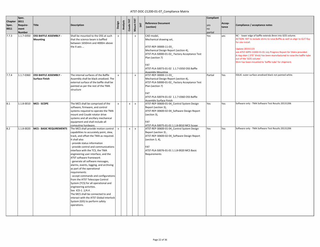
7.7.3 1.1.7‐0350 OSS BAFFLE ASSEMBLY ‐ Mounting
Shall be mounted to the OSS at such that the science beam is baffled between 1650mm and 4000m above the X axis …
x x CAD model,Mechanical drawing set,
ATST‐REP‐30000‐11‐03_Mechanical Design Report (section 4),ATST‐PLA‐50000‐01‐02_ Factory Acceptance Test Plan (section 7)
FATATST‐PLA‐50073‐01‐02 1.1.7‐0350 OSS Baffle Assembly Mounting
Yes yes NC ‐ lower edge of baffle extends 8mm into GOS volume.ACTION: IMT to include shims to raise Baffle as well as align to GUT Ray for site install.
Update 20151123see ATST‐MPR‐11000‐55‐01 July Progress Report for Shims provided.A ring shim (.375" thick) has been manufactured to raise the baffle tube out of the 'GOS volume'.Shim has been mounted to 'baffle tube' for shipment.
7.7.4 1.1.7‐0360 OSS BAFFLE ASSEMBLY ‐ Surface Finish
The internal surfaces of the Baffle Assembly shall be black anodized. The external surface of the baffle shall be painted as per the rest of the TMA structure
x x ATST‐REP‐30000‐11‐03_Mechanical Design Report (section 4),ATST‐PLA‐50000‐01‐02_ Factory Acceptance Test Plan (section 7)
FATATST‐PLA‐50074‐01‐02 1.1.7‐0360 OSS Baffle Assembly Surface Finish
Partial Yes ISSUE: outer surface anodised black not painted white.
8.1 1.1.8‐0010 MCS ‐ SCOPE The MCS shall be comprised of the software, firmware, and control systems required to operate the TMA mount and Coudé rotator drive systems and all ancillary mechanical equipment and shall include all computing hardware.
x x x ATST‐REP‐30600‐01‐04_Control System Design Report (section 3),ATST‐REP‐30600‐02‐04_Software Design Report (section 3),
FATATST‐PLA‐50075‐01‐01 1.1.8‐0010 MCS Scope
Yes Yes Software only ‐ TMA Software Test Results 20131206
8.2 1.1.8‐0020 MCS ‐ BASIC REQUIREMENTS The MCS shall provide motion control capabilities to accurately point, slew, track, and offset the TMA as required. It shall also‐ provide status information‐ provide control and communications interface with the TCS, the TMA engineering user interface, and the ATST software framework ‐ generate all software messages, alarms, events, logging, and archiving as part of the operational requirements‐ accept commands and configurations from the ATST Telescope Control System (TCS) for all operational and engineering activities.See ICD‐1 .1/4.4 .The MCS shall be connected to and interact with the ATST Global Interlock System (GIS) to perform safety operations.
x x x ATST‐REP‐30600‐01‐04_Control System Design Report (section 3) ,ATST‐REP‐30600‐02‐04_Software Design Report (section 3, 4),
FATATST‐PLA‐50076‐01‐01 1.1.8‐0020 MCS Basic Requirements
Yes Yes Software only ‐ TMA Software Test Results 20131206
Page 22 of 36

ATST‐DOC‐21200‐01‐07_Compliance Matrix
ChapterSpec.0011
Spec.0011Require‐ment Number
Title Description
Design
Analysis
Coud
e FA
T
Mou
nt FAT
SAT Reference Document
(section)
Compliant
yesnopartial
Accep‐tance
Compliance / acceptance notes
8.3 1.1.8‐0030 MCS ‐ REQUIRED SOFTWARE PRACTICES
The MCS shall conform to ‐ the ATST software requirements as per SPEC‐0022 and use‐ the ATST Common Services Framework for all communications, commands, events, logging, archiving, and database functions‐ the ATST Common Services Framework to build Controllers for, at a minimum, the top‐level MCS controller, mount azimuth controller, mount altitude controller, Coudé azimuth controller, M1 mirror cover controller, and status and sensing system controller.‐ software libraries approved by ATST for the implementation of the MCS; and‐ use a source code repository for all developed MCS
x x x ATST‐REP‐30600‐02‐04_Software Design Report (section 3, 5),
FATATST‐PLA‐50077‐01‐01 1.1.8‐0030 Required Software Practices
Yes Yes Software only ‐ TMA Software Test Results 20131206
8.4 1.1.8‐0040 MCS ‐ CONTROL The MCS shall monitor and control all TMA sub‐systems through the approved system interfaces.All signals generated or received by the MCS and internal to the TMA shall be made available to the TCS or the Engineering Display as per the ATST Common Services Framework.
x ATST‐REP‐30600‐02‐04_Software Design Report (section 4, 7)
yes yes
8.5 1.1.8‐0050 MCS ‐ DEFAULT STATE The MCS shall have a defined default state for all hardware and equipment that it controls (inert, non¬moving, non‐powered condition).
x x x ATST‐REP‐30600‐02‐04_Software Design Report (section 5),
FATATST‐PLA‐50078‐01‐01 1.1.8‐0050 Default State
Yes Yes Software only ‐ TMA Software Test Results 20131206
8.6 1.1.8‐0060 MCS ‐ RESTART The MCS shall perform all requests sent through its interface without need of reboot or re‐initialization, unless the request demands such an operation.
x x x ATST‐REP‐30600‐02‐04_Software Design Report (section 5, 7),
FATATST‐PLA‐50079‐01‐01 1.1.8‐0060 Restart
Yes Yes Software only ‐ TMA Software Test Results 20131206
8.7 1.1.8‐0070 MCS ‐ HEALTH The MCS shall be able to determine whether the current state of the TMA is within operational specifications and shall report this current state as health, as per ICD‐1.1/4.4
x x x ATST‐REP‐30600‐02‐04_Software Design Report (section 5),
FATATST‐PLA‐50080‐01‐01 1.1.8‐0070 Health
Yes Yes Software only ‐ TMA Software Test Results 20131206
8.8 1.1.8‐0080 MCS ‐ LOGGING The MCS shall log pertinent data to the ATST facility log mechanism as state changes, configuration changes, errors, alarms and warnings. The logging level shall be user selectable for the depth of information, per the ATST logging facility definitions of logging levels in SPEC‐0022.
x x x ATST‐REP‐30600‐02‐04_Software Design Report (section 5),
FATATST‐PLA‐50081‐01‐01 1.1.8‐0080 Logging
Yes Yes Software only ‐ TMA Software Test Results 20131206
Page 23 of 36

ATST‐DOC‐21200‐01‐07_Compliance Matrix
ChapterSpec.0011
Spec.0011Require‐ment Number
Title Description
Design
Analysis
Coud
e FA
T
Mou
nt FAT
SAT Reference Document
(section)
Compliant
yesnopartial
Accep‐tance
Compliance / acceptance notes
8.9 1.1.8‐0090 MCS ‐ AVAILABILITY The MCS shall be available to accept or reject commands at all times while in a running state and shall not block any commands.
x x x ATST‐REP‐30600‐02‐04_Software Design Report (section 3),
FATATST‐PLA‐50082‐01‐01 1.1.8‐0090 Availability
Yes Yes Software only ‐ TMA Software Test Results 20131206
8.10 1.1.8‐0100 MCS ‐ PERSISTENCE OF DATA The MCS shall recover all static information required to operate after a restart or reboot (zero points, lookup tables, and configuration parameters …).
x x x ATST‐REP‐30600‐02‐04_Software Design Report (section 5),
FATATST‐PLA‐50083‐01‐01 1.1.8‐0100 Persistence of Data
Yes Yes Software ‐ TMA Software Test Results 20131206Coude Hardware ‐ CompliantMount Hardware ‐ Compliant
8.11 1.1.8‐0110 MCS ‐ TIME TO ACCEPT OR REJECT COMMAND
The MCS accept or reject a command given on its public interface within 0.1 seconds.
x x x x ATST‐REP‐30600‐02‐04_Software Design Report (section 5),
FATATST‐PLA‐50084‐01‐01 1.1.8‐0110 Time to Accept or Reject Command
Yes Yes Software only ‐ TMA Software Test Results 20131206
8.12 1.1.8‐0120 MCS ‐ BOOT TIME The MCS shall be operational within five (5) minutes of a cold, power‐off start of its hardware.
x x x x ATST‐REP‐30600‐02‐04_Software Design Report (section 3),
FATATST‐PLA‐50085‐01‐01 1.1.8‐0120 Boot Time
Yes Yes Software only ‐ TMA Software Test Results 20131206
8.13 1.1.8‐0130 MCS ‐ APPLICATION OF INFORMATION
The MCS shall apply any external information (i.e., offsets or adjustments) within 0.1 seconds.
x x x x ATST‐REP‐30600‐02‐04_Software Design Report (section 5),
FATATST‐PLA‐50086‐01‐01 1.1.8‐0130 Application of Information
Yes Yes Software only ‐ TMA Software Test Results 20131206
8.14 1.1.8‐0140 MCS ‐ COMPUTER RESOURCES During normal operations, the MCS shall not consume more than 50% of its processing capability. The system shall not consume more than 50% of its hard disk capacity.
x x x x ATST‐REP‐30600‐02‐04_Software Design Report,
FATATST‐PLA‐50087‐01‐01 1.1.8‐0140 Computer Resources
Yes Yes Software only ‐ TMA Software Test Results 20131206
8.15 1.1.8‐0150 MCS ‐ ENGINEERING USER INTERFACE
The MCS shall supply an engineering user interface for the system operating software, which exercises all the functionality of the MCS and shall be useful for actual operations within the ATST (TMA‐TCS software interface defined by ICD‐ 1.1/4.4 to control and monitor the MCS).
x x x ATST‐REP‐30600‐01‐04_Control System Design Report, (section 3),ATST‐REP‐30600‐02‐04_Software Design Report (section 5. 10),
FATATST‐PLA‐50088‐01‐01 1.1.8‐0150 Engineering User Interface
Yes Yes Software only ‐ TMA Software Test Results 20131206
8.16 1.1.8‐0160 MCS ‐ LOCAL INTERLOCK CONTROLLER
The MCS shall respond to interlock events as per the Common Services Framework, SPEC‐0022‐1 by immediately discontinuing all actions and motions, placing all mechanisms in a powered off or de‐energized state, and rejecting all further actions during the interlock condition.
x x x ATST‐REP‐30600‐01‐04_Control System Design Report (section 3),ATST‐REP‐30600‐02‐04_Software Design Report (section 4),
FATATST‐PLA‐50089‐01‐02 1.1.8‐0160 Local Interlock Controller
Yes Yes Software ‐ TMA Software Test Results 20131206Coude Hardware ‐ CompliantMount Hardware ‐ Compliant
Page 24 of 36

ATST‐DOC‐21200‐01‐07_Compliance Matrix
ChapterSpec.0011
Spec.0011Require‐ment Number
Title Description
Design
Analysis
Coud
e FA
T
Mou
nt FAT
SAT Reference Document
(section)
Compliant
yesnopartial
Accep‐tance
Compliance / acceptance notes
8.17 1.1.8‐0170 MCS ‐ ENGINEERING OPERATIONS
The MCS shall have an operational and engineering mode (e.g. moving a telescope axis beyond the software range of travel).
x x x ATST‐REP‐30600‐01‐04_Control System Design Report (section 3),ATST‐REP‐30600‐02‐04_Software Design Report (section 5, 10),
FATATST‐PLA‐50090‐01‐01 1.1.8‐0170 Engineering Operations
Yes Yes Software only ‐ TMA Software Test Results 20131206
8.18 1.1.8‐0180 MCS ‐ ETHERNET ON THE CONTROL LAN
The MCS shall use Ethernet for all communications on the Control LAN.
x x ATST‐REP‐30600‐01‐04_Control System Design Report (section 3),ATST‐REP‐30600‐02‐04_Software Design Report (section 3),ATST‐PLA‐50000‐01‐02_ Factory Acceptance Test Plan (section 7)
Yes Yes Software only ‐ TMA Software Test Results 20131206
8.19 1.1.8‐0190 MCS ‐ CONFIGURATION IDENTIFIERS
The MCS shall use the proper configuration identifier in all communications.
x x x x ATST‐REP‐30600‐02‐04_Software Design Report (section 5),
FATATST‐PLA‐50092‐01‐01 1.1.8‐0190 Configuration Identifiers
Yes Yes Software only ‐ TMA Software Test Results 20131206
8.20 1.1.8‐0200 MCS ‐ TIME STANDARD The MCS shall use International Atomic Time (TAI) in all calculations, in all data distribution, logging and archiving.
x x ATST‐REP‐30600‐02‐04_Software Design Report (section 5),
FATATST‐PLA‐50093‐01‐01 1.1.8‐0200 Time Standard
Partial Yes ISSUE: GPS time sync not available so full check not possible.
8.21 1.1.8‐0210 MCS ‐ PUBLIC INTERFACES Contractor shall document all public software interfaces from the source code using doxygen.
x x ATST‐REP‐30600‐02‐04_Software Design Report (section 3),
FATATST‐PLA‐50094‐01‐01 1.1.8‐0210 Public Interfaces
Yes Yes Software only ‐ TMA Software Test Results 20131206
8.22.1 1.1.8‐0220 MCS ‐ Range of Travel The MCS shall control the TMA through its full range of travel in mount azimuth, mount altitude, and Coudé rotation. Additionally: Engineering mode travel.
x x x x ATST‐REP‐30600‐01‐04_Control System Design Report (section 4),ATST‐REP‐30600‐02‐04_Software Design Report (section 5),
FATATST‐PLA‐50095‐01‐01 1.1.8‐0220 Range of Travel
Yes Yes Software ‐ TMA Software Test Results 20131206Coude Hardware ‐ CompliantMount Hardware ‐ Compliant
8.22.2 1.1.8‐0230 MCS ‐ Zenith The MCS shall generate a status indication when it is within 0.5 degreesof zenith.
x x x x ATST‐REP‐30600‐02‐04_Software Design Report (section 7),
FATATST‐PLA‐50096‐01‐01 1.1.8‐0230 Zenith
Yes Yes Software ‐ TMA Software Test Results 20131206Coude Hardware ‐ n/aMount Hardware ‐ Compliant
8.22.3 1.1.8‐0240 MCS ‐ Rate of Travel The MCS shall be capable of moving the TMA about its axes of rotation at, but no faster than, the specified maximum rates of travel.
x x x x ATST‐REP‐30600‐01‐04_Control System Design Report (section 4),ATST‐REP‐30600‐02‐04_Software Design Report (section 7),ATST‐PLA‐50000‐01‐02_ Factory Acceptance Test Plan (section 7), ATST‐PLA‐80000‐01‐02_ Site Acceptance Test Plan (section 7)
Yes Yes Software only ‐ TMA Software Test Results 20131206
Page 25 of 36

ATST‐DOC‐21200‐01‐07_Compliance Matrix
ChapterSpec.0011
Spec.0011Require‐ment Number
Title Description
Design
Analysis
Coud
e FA
T
Mou
nt FAT
SAT Reference Document
(section)
Compliant
yesnopartial
Accep‐tance
Compliance / acceptance notes
8.22.4 1.1.8‐0250 MCS ‐ Pointing The MCS shall be able to move each telescope axis in the quickest possible path to a demand position and keep each telescope axis within the required position and velocity tolerances.
x x x x ATST‐REP‐30600‐02‐04_Software Design Report (section 6),
FATATST‐PLA‐50098‐01‐01 1.1.8‐0250 Pointing
Yes Yes Software ‐ TMA Software Test Results 20131206Coude Hardware ‐ CompliantMount Hardware ‐Compliant
8.22.5 1.1.8‐0260 MCS ‐ Tracking and Following The MCS shall ‐ move at a nearly constant rate across the sky under the influence of an external trajectory,‐ shall maintain the pointing requirements for each axis while following the trajectory stream‐ obey the specifications of the external trajectory as defined by the interface document between the TCS and TMA (ICD‐1.1/4.4).
x x x x ATST‐REP‐30600‐02‐04_Software Design Report (section 4, 6),
FATATST‐PLA‐50099‐01‐01 1.1.8‐0260 Tracking and Following
Yes Yes Software ‐ TMA Software Test Results 20131206Coude Hardware ‐ CompliantMount Hardware ‐ Compliant
8.22.6 1.1.8‐0270 MCS ‐ Position Offset The MCS shall accept offset positions from the current position for the three major TMA axes (azimuth, altitude, Coudé) and shall move to the new position through the most efficient motion profile.
Additional clarifications: see TD‐0052.
x x x x ATST‐REP‐30600‐02‐04_Software Design Report (section 6),
FATATST‐PLA‐50100‐01‐01 1.1.8‐0270 Position Offset
Yes Yes Software ‐ TMA Software Test Results 20131206Coude Hardware ‐ CompliantMount Hardware ‐ Compliant
8.22.7 1.1.8‐0280 MCS ‐ In Position The MCS shall continuously determine and report if it is within the tolerances. The tolerances shall be user‐configurable.
x x x x ATST‐REP‐30600‐02‐04_Software Design Report (section 5),
FATATST‐PLA‐50101‐01‐01 1.1.8‐0280 In Position
Yes Yes Software ‐ TMA Software Test Results 20131206Coude Hardware ‐ CompliantMount Hardware ‐ Compliant
8.23.1 1.1.8‐0290 MCS ‐ Hydrostatic Oil Bearings If hydrostatic oil bearings are employed, the MCS shall control their operation and monitor their status …
n/a n/a n/a n/a n/a ‐ yes yes
8.23.2 1.1.8‐0300 MCS ‐ Status Information The MCS shall monitor and report the current status or change of status of the servo systems as per the TMA/TCS ICD (rate no faster than 10 Hz per data sample, rate shall be variable under user control for each status item).
x x x ATST‐REP‐30600‐02‐04_Software Design Report (section 4),
FATATST‐PLA‐50105‐01‐01 1.1.8‐0300 Status Information
yes yes Software only ‐ TMA Software Test Results 20131206
8.23.3 1.1.8‐0310 MCS ‐ High‐Speed Status Information
The MCS shall provide the capability of selecting one or more status items for high‐speed reporting (rate 2 KHz), the high‐speed output shall use the ATST archive service as specified in SPEC‐0022‐1.
x x x x ATST‐REP‐30600‐02‐04_Software Design Report (section 5),
FATATST‐PLA‐50102‐01‐01 1.1.8‐0310 High Speed Status Information
Yes Yes Software only ‐ TMA Software Test Results 20131206
Page 26 of 36

ATST‐DOC‐21200‐01‐07_Compliance Matrix
ChapterSpec.0011
Spec.0011Require‐ment Number
Title Description
Design
Analysis
Coud
e FA
T
Mou
nt FAT
SAT Reference Document
(section)
Compliant
yesnopartial
Accep‐tance
Compliance / acceptance notes
8.23.4 1.1.8‐0320 MCS ‐ Laser Control The two lasers on the TMA mount structure are used to align the M1 entrance aperture with the Enclosure‟s entrance aperture. Although the lasers are not a part of the TMA Work, the control and monitoring of the lasers shall be a part of the MCS.
n/a n/a n/a n/a n/a ATST‐REP‐30600‐02‐04_Software Design Report (section 5),ATST‐PLA‐50000‐01‐02_ Factory Acceptance Test Plan 8section 7), ATST‐PLA‐80000‐01‐02_ Site Acceptance Test Plan (section 7)
yes yes
9.2 1.1.9‐0010 GIS ‐ BASIC REQUIREMENTS The TMA Contractor is required to facilitate management of the TMA subsystems' local interlocks and safety limits through a subsystem part of the GIS referred as a Local Interlock Controller (LIC).The TMA shall have two dedicated LICs, one of which provides interlock control to the mount structure, drives, and ancillary mechanical equipment, and the other to the Coudé rotator structure, drives, and ancillary mechanical equipment.
x x x x ATST‐REP‐30700‐90‐03_Interlock System Design Report (all sections),
FATATST‐PLA‐50106‐01‐01_1.1.9‐0010 LIC ‐ Basic Requirements
Yes Yes Coude Rotator (CLIC) ‐ compliantMount (MLIC) ‐ Compliant
9.3 1.1.9‐0020 GIS ‐ SCOPE The TMA interface to the GIS shall:‐ provide all required safety interlock and safety limits as outlined in ICD 1.1/4.5,‐ follow the hazard analysis,‐ implement additional necessary safety interlock solutions,‐ connect all interlock and safety limits of the local subsystem,‐ provide the programmed LIC that ensures delivery of an independently safe system,‐ provide enabled control connectivity of all hazardous energy sources within the TMA,‐ allow temporary exemption to the operational interlock requirement during testing/commissioning,‐ provide interlocking solutions that require operator action in order to re‐establish the energy system,‐ provide connectivity, to control all emergency stop conditions.
x x x x ATST‐REP‐30700‐90‐03_Interlock System Design Report (all sections),Hazard Analysis (Sheet "Worksheet)
FATATST‐PLA‐50107‐01‐01_1.1.9‐0020 LIC ‐ Scope
Yes Yes Coude Rotator (CLIC) ‐ compliantMount (MLIC) ‐ Compliant
Page 27 of 36
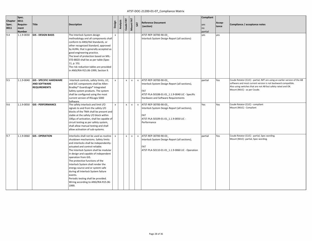
ATST‐DOC‐21200‐01‐07_Compliance Matrix
ChapterSpec.0011
Spec.0011Require‐ment Number
Title Description
Design
Analysis
Coud
e FA
T
Mou
nt FAT
SAT Reference Document
(section)
Compliant
yesnopartial
Accep‐tance
Compliance / acceptance notes
9.4 1.1.9‐0030 GIS ‐ DESIGN BASIS The Interlock System design methodology and all components shall conform to ANSI/ISA Standards, or other recognized Standard, approved by AURA, that is generally accepted as good engineering practice.The level of protection based on MIL‐STD‐882D shall be as per table (Spec 11, p. 55).The risk reduction tables are provided in ANSI/RIA R15.06‐1999, Section 9.
x ATST‐REP‐30700‐90‐03_Interlock System Design Report (all sections)
yes yes
9.5 1.1.9‐0040 GIS ‐ SPECIFIC HARDWARE AND SOFTWARE REQUIREMENTS
Interlock controls, safety limits, LIC, and GIC components shall be Allen‐Bradley® GuardLogix® Integrated Safety system products. The system shall be configured using the most current version of RSLogix 5000 Software.
x x x x ATST‐REP‐30700‐90‐03_Interlock System Design Report (all sections),
FATATST‐PLA‐50108‐01‐01_1.1.9‐0040 LIC ‐ Specific Hardware and Software Requirements
partial Yes Coude Rotator (CLIC) ‐ partial, IMT are using an earlier version of the AB software and most current version is not backward compatible.Also using switches that are not AB but safety rated and OK.Mount (MLIC) ‐ as per Coude.
9.6 1.1.9‐0050 GIS ‐ PERFORMANCE The safety interlock and limit I/O signals to and from the safety I/O blocks of the TMA shall be present and stable at the safety I/O block within 100μs of activation, shall be capable of circuit testing as per safety system, shall allow manual testing and shall allow activation of sub‐systems.
x x x x ATST‐REP‐30700‐90‐03_Interlock System Design Report (all sections),
FATATST‐PLA‐50109‐01‐01_1.1.9‐0050 LIC ‐ Performance
Yes Yes Coude Rotator (CLIC) ‐ compliantMount (MLIC) ‐ Compliant
9.7 1.1.9‐0060 GIS ‐ OPERATION Interlocks shall not be used as routine shutdown mechanisms. Safety limits and interlocks shall be independently‐actuated and control‐reliable.The Interlock System shall be modular in design and capable of independent operation from GIS.The protective functions of the Interlock System shall render the energy source and or system safe during all Interlock System failure events.Periodic testing shall be provided.Wiring according to ANSI/RIA R15.06‐1999.
x x x x ATST‐REP‐30700‐90‐03_Interlock System Design Report (all sections),
FATATST‐PLA‐50110‐01‐01_1.1.9‐0060 LIC ‐ Operation
partial Yes Coude Rotator (CLIC) ‐ partial, Spec wording.Mount (MLIC) ‐partial, Spec wording.
Page 28 of 36

ATST‐DOC‐21200‐01‐07_Compliance Matrix
ChapterSpec.0011
Spec.0011Require‐ment Number
Title Description
Design
Analysis
Coud
e FA
T
Mou
nt FAT
SAT Reference Document
(section)
Compliant
yesnopartial
Accep‐tance
Compliance / acceptance notes
9.8 1.1.9‐0070 GIS ‐ SYSTEM INTEGRITY Independent of other subsystems, the TMA LIC shall respond to local fault and limit conditions generating its subsystem outputs which disable functions providing a control reliable safe action.The LIC shall operate with non‐switched, UPS power as per SPEC‐0063. All interlocks and safety inputs shall fail in a safe condition regardless of power state.All control signals required by the LIC shall be input to the process control hardware trough the LIC via Safety I/O devices.
x x x ATST‐REP‐30700‐90‐03_Interlock System Design Report (all sections),
FATATST‐PLA‐50111‐01‐01_1.1.9‐0070 LIC ‐ System Integrity
partial Yes Coude Rotator (CLIC) ‐ non switched UPS not available at Factory.Mount (MLIC) ‐ Partial Compliance—Test completed as written. Non‐switched UPS not available atfactory.
9.9 1.1.9‐0080 GIS ‐ INTERFACE TO GIS The LIC shall enable and disable specific devices in response to input from the GIS and shall communicate with the GIS using a dedicated network of Ethernet/IP with CIP Safety protocol as specified in ICD 1.5/4.5. The LIC shall provide status of all interlocks states to the GIC.
x x x x ATST‐REP‐30700‐90‐03_Interlock System Design Report (all sections),
FATATST‐PLA‐50112‐01‐01_1.1.9‐0080 LIC ‐ Interface to GIS
Yes Yes Coude Rotator (CLIC) ‐ compliantMount (MLIC) ‐ Compliant
9.10 1.1.9‐0090 GIS ‐ MAINTAINABILITY A controlled means for reconfiguration and bypassing of components of the Interlock System shall be established and documented.
x x x ATST‐REP‐30700‐90‐03_Interlock System Design Report (all sections),
FATATST‐PLA‐50113‐01‐01_1.1.9‐0090 LIC ‐ Maintainability
Yes Yes Coude Rotator (CLIC) ‐ compliantMount (MLIC) ‐ compliant
9.11 1.1.9‐0100 GIS ‐ OTHER REQUIREMENTS Redundant circuits shall not share cables and shall be separated physically on circuit boards and terminal strips. Redundant systems shall be configured independently.Lines and component labeling/identification shall be part of the TMA Safety System.Suitable protection shall be provided to preserve physical integrity of all components.
x x x ATST‐REP‐30700‐90‐03_Interlock System Design Report (all sections),ATST‐PLA‐50000‐01‐02_ Factory Acceptance Test Plan (section 7)
Yes Yes Coude Rotator (CLIC) ‐ compliantMount (MLIC) ‐compliant
9.12 1.1.9‐0110 GIS ‐ EMERGENCY STOP SYSTEM
The Emergency Stop System is part of the GIS. The specification and requirements for the TMA part of this system are defined in ICD 1.1/4.5 TMA to GIS.
x x x x ATST‐REP‐30700‐90‐03_Interlock System Design Report (all sections),
FATATST‐PLA‐50115‐01‐01_1.1.9‐0110 LIC ‐ Emergency Stop System
Yes Yes Coude Rotator (CLIC) ‐ compliantMount (MLIC) ‐ compliant
Page 29 of 36

ATST‐DOC‐21200‐01‐07_Compliance Matrix
ChapterSpec.0011
Spec.0011Require‐ment Number
Title Description
Design
Analysis
Coud
e FA
T
Mou
nt FAT
SAT Reference Document
(section)
Compliant
yesnopartial
Accep‐tance
Compliance / acceptance notes
10.1 1.1‐0300 PART LAYOUT & ORGANIZATION
The overall part and component count shall be minimized, fundamental elegance of design, exhibiting high efficiency usage of materials and components is a goal.To the extent possible, subsystems that are off the shelf or previously designed shall be used. The most efficient and effective manufacturing processes shall be used.Easy of mounting/dismounting and servicing shall be possible. Critical parts that have to be accurately aligned shall be mounted with alignment screws and locking mechanisms.
x x x CAD model,Mechanical drawing set,
FATATST‐PLA‐50116‐01‐01 1.1‐0300 Part Layout and Organization
Yes Yes Coude Rotator / Coude Cable Wrap ‐ compliantMount ‐ compliantMount Azimuth Cable Wrap ‐ compliant
10.2 1.1‐0310 CODES, REGULATIONS, & STANDARDS
Codes to be used shall include but are not limited to:‐ International Building Code;‐ AISC American Institute of Steel Construction AISC Manual of Steel Construction, 9th ed. AISC Specification for the Design, Fabrication, And Erection of ‐ AWS American Welding Society AWS D1.1‐92‐ ASTM American Society for Testing and Materials;‐ ANSI American National Standards Institute;‐ SSPC Steel Structures Painting Council, Good Painting Practice, Steel Structure Painting Manual Vol.1 Systems and Specifications, Steel Structures Painting Manual Vol. 2; and‐ HIOSHA Title 12 Standards for General Industry and Construction.Any material shall be US Standards.
x x x for example:ATST_SPE‐30000‐01‐01_Steel Structure Spec(sections 1, 2),ATST‐ANA‐22100‐02‐02_Strength Analysis (section 2)ATST‐ANA‐22200‐02‐03_Strength Analysis (section 2)ATST‐PLA‐50000‐01‐02_ Factory Acceptance Test Plan (section 7)
FATATST‐PLA‐50117‐01‐01 1.1‐0310 Codes and RegulationsATST‐PLA‐50117‐01‐01 1.1‐0310_Coude FAT Safety Checklist 20140505ATST‐PLA‐50117‐01‐01 1.1‐0310_Mount FAT Safety Checklist 20150129.xlsx
Yes yes Coude Rotator ‐ see ATST‐PLA‐50117‐01‐01 1.1‐0310_Coude FAT Safety Checklist 20140505Mount ‐ see ATST‐PLA‐50117‐01‐01 1.1‐0310_Mount FAT Safety Checklist 20150129.xlsx
Update 20150717 all factory based actions noted in the punch list have been completed. so noting this now as FAT compliant.
Page 30 of 36

ATST‐DOC‐21200‐01‐07_Compliance Matrix
ChapterSpec.0011
Spec.0011Require‐ment Number
Title Description
Design
Analysis
Coud
e FA
T
Mou
nt FAT
SAT Reference Document
(section)
Compliant
yesnopartial
Accep‐tance
Compliance / acceptance notes
10.3 1.1‐0320 DRAWINGS & DOCUMENTS CAD 3D solid models of the Assembly generated or transferable to SolidWorks. Detail design drawings conform to ASME Y14.5M‐1994 in third‐angle projection with metric units (and inch in parentheses).Finite Element Analysis in (or transferable to) the latest commercially available version of ANSYS.Electronics and electrical schematics generated or transferable to Altium and also in PDF format.Models and simulations of control systems generated or transferable to MATLAB / Simulink.
x CAD model, FE model, Simulation model,Mechanical, Drawing set, Electrical Drawing set
yes yes
10.4 1.1‐0330 STRUCTURAL DESIGN A factor of Safety of 2.5 under any combination of operational and environmental loading shall be used. The load combination shall be done by an AURA approved standard. The joint design shall be approved by AURA.
x CAD model,ATST‐ANA‐22100‐02‐02_Strength Analysis (section 6)ATST‐ANA‐22200‐02‐03_Strength Analysis (section 6)
yes yes
10.5 1.1‐0340 ELECTRICAL DESIGN The TMA allocated power budget on Site shall be as specified in SPEC‐0063, implement energy efficiency technologies to minimize power usage shall be used.Requirements: over‐current protection, main line circuit breaker or power switch, comply with latest release of the U. S. National Electrical Code, safety grounds, minimize electromagnetic interference (EMI), EMI certified and comply with FCC regulation Part 15, power and signal cables shall be shielded, proper and appropriate strain relief to minimize effect of cabling loads, power and signal cables shall be routed separately. TMA system Electronics shall be mounted in Standard Racks provided by Contractor as specified in SPEC‐0063, labeled at both terminations as per SPEC‐0063. The labeling system shall be easily traceable through the system schematics.
x x x Mechanical, Drawing set, Electrical Drawing set,ATST‐LIS‐21300‐20‐12_ATST TMA Power and Torque Budget (sheet "power budget", "total"),ATST‐LIS‐30600‐01‐10_Cable and Hoses List (all sheets),ATST‐REP‐30600‐01‐04_Control System Design Report (all sections),ATST‐SPE‐30000‐16‐01_TMA Switch Cabinet Specification (all sections),ATST‐DWG‐30600‐01‐05_TMA Harness Master Diagram(all sheets),
FATATST‐PLA‐50118‐01‐02 1.1‐0340 Electrical Design
Yes yes Coude ‐ see ATST‐PLA‐50118‐01‐02 1.1‐0340_Coude FAT Electrical PunchlistMount ‐ see ATST‐PLA‐50118‐01‐03 1.1‐0340_Mount FAT Electrical Punchlist
Update 20151201Electrical Punchlists complete
Page 31 of 36

ATST‐DOC‐21200‐01‐07_Compliance Matrix
ChapterSpec.0011
Spec.0011Require‐ment Number
Title Description
Design
Analysis
Coud
e FA
T
Mou
nt FAT
SAT Reference Document
(section)
Compliant
yesnopartial
Accep‐tance
Compliance / acceptance notes
10.6 1.1‐0350 THERMAL DESIGN ‐ Components in the Coudé lab area or above the telescope level floor shall not dissipate more than 20 watts of heat to the observing environment during any operational state.‐ Systems above M1 level and within Coudé lab area shall not have a surface temperature which differs more than +1.5°C / ‐3°C from the operational ambient air. This shall assume 0 m/s wind speed within the open dome and the telescope pointing to zenith.‐ Systems below M1 level shall not have a surface temperature which differs more than +1.5°C / ‐5°C from the operational ambient air. This shall assume 0 m/s wind speed within the open dome and the telescope pointing to zenith.
x x x x ATST‐LIS‐21300‐20‐12_ATST TMA Power and Torque Budget (sheet "power budget"),ATST‐ANA‐22200‐03‐01 Thermal Analysis Coude (all sections),ATST‐ANA‐22100‐03‐02 Thermal Analysis Mount (all sections),ATST‐REP‐30000‐11‐03 Mechanical Design Report (section 4),
FATATST‐PLA‐50119‐01‐01 1.1‐0350 Thermal Design
Partial Yes Coude Rotator / Coude Cable Wrap ‐ compliantMount ‐ see ATST‐PLA‐50119‐01‐01 1.1‐0350_TMA_Thermography Report & ActionsMount Azimuth Cable Wrap ‐ Compliant
Update 20160223DKIST_TMA_Thermography Report ‐ Final Signed 20160223complete ‐ followed up with actions for site assembly.
DKIST TMA Pipework Inspection ‐ Final Signed 20160223complete ‐ followed up with actions for site assembly.
10.7 1.1‐0360 ENVIRONMENTAL CONDITIONS
Site Survival Conditions: Temp. ‐10 … 27 °C, +/‐ 15 °C/hour, wind max. 30 m/s, humidity max. 95%Site Operational Conditions Mount: Temp. ‐ 2 … 22 °C, +/‐ 2 °C/hour, wind max. 5 m/s, humidity max. 60%Site Operational Cond. Coudé: Temp. 18 … 22 °C, +/‐ 0,5 °C/hour, wind max. 0,5 m/s, humidity max. 60%
x x x x ATST‐ANA‐22200‐03‐01 Thermal Analysis Coude (all sections),All Sub Specifications (ATST‐SPE‐30000‐XX‐XX)
FATATST‐PLA‐50120‐01‐01 1.1‐0360 Environmental Condition
Yes Yes Coude Rotator / Coude Cable Wrap ‐ compliantMount ‐ compliantMount Azimuth Cable Wrap ‐ compliant
10.8 1.1‐0370 RELIABILITY & LIFETIME The design lifetime of the ATST facility shall be 40 years (TD‐0035). The total non‐scheduled down time does not exceed two (2) days per year, the Mean Time Between Failures (MTBF) shall be no less than 9000 hours of operation (a failure is defined as an event causing complete loss of observing capability and which cannot be recovered by corrective maintenance (including fault identification) in less than 2 hours).
x ATST‐ANA‐21500‐01‐02_Reliability and Availability (all sections)
yes yes
Page 32 of 36

ATST‐DOC‐21200‐01‐07_Compliance Matrix
ChapterSpec.0011
Spec.0011Require‐ment Number
Title Description
Design
Analysis
Coud
e FA
T
Mou
nt FAT
SAT Reference Document
(section)
Compliant
yesnopartial
Accep‐tance
Compliance / acceptance notes
10.9 1.1‐0380 MAINTENANCE TMA shall be configured such that normal maintenance requirements are as follows:‐ Weekly inspections and simple interventions shall take less than 6 hours total per week;‐ Six monthly activities shall take less than 24 hours total (e.g. applying grease to bearings).Maintenance shall be accomplished by two trained observatory staff members with a minimum of specialist tooling, specialized tooling to be provided by Contractor.
x x x CAD model,
ATST_DOC‐30900‐02‐02Maintenance Manual (all sections),
FATATST‐PLA‐50121‐01‐02 1.1‐0380 Maintenance
Yes Yes Coude Rotator / Coude Cable Wrap ‐ compliantMount ‐ compliantMount Azimuth Cable Wrap ‐ compliant
10.10 1.1‐0390 COMMONALITY OF DESIGNS Identical equipment and designs throughout the TMA shall be used for different subsystems (e.g. azimuth axial bearing mount structure and the Coudé rotator structure).
x CAD model,Mechanical drawing set
yes yes
10.11 1.1‐0400 OPERATIONAL SPARES Operational spares are spares provided with the TMA for use during operation after acceptance. Items that shall be spared by the Contractor are those that:‐ are expected to be replaced within the first two years after delivery‐ could constitute a single point failure resulting in complete shutdown of the system‐ are specific to the TMA and have a lead time of more than three (3) months
x x ATST‐REP‐30000‐31‐02_Spare Part List (all sections),ATST‐PLA‐50000‐01‐02_ Factory Acceptance Test Plan (section 7)
Is applicable to both Mount and Coude, will verify the spares at Mount FAT for both Coude and Mount.
FATATST‐PLA‐50122‐01‐01 1.1‐0400 Operational Spares
Yes yes NC ‐ spares have not all been purchased.ACTION: Final spares inventory to be checked at packing and shipping phase.
Update 20151201Spares packed and shipped. Full inventory will be checked by AURA during unpacking.
10.12 1.1‐0410 MATERIALS AND WORKMANSHIP
All materials used in the Work shall be new and of high grade commercial quality, free from defects etc.The workmanship shall be of high grade of commercial practice and adequate to achieve the requirements of specs, drawings etc.All manufacturing processes shall be specified and performed to achieve properties required.All metal edges shall be free of burrs and sharp corners.Material records shall be maintained by Contractor in accordance with ISO 9001‐2000.
x x x e.g.ATST‐SPE‐30000‐01‐03_Steel Structure Specification(all sections),
FATATST‐PLA‐50123‐01‐01 1.1‐0410_Material and Workmanship
Yes yes Coude see ‐ ATST‐PLA‐50123‐01‐01 1.1‐0410_Coude FAT Punchlist 20140506
Mount see ‐ ATST‐PLA‐50123‐01‐01 1.1‐0410_Mount FAT Punchlist 20150407
Update 20151201Punchlists complete.
Page 33 of 36

ATST‐DOC‐21200‐01‐07_Compliance Matrix
ChapterSpec.0011
Spec.0011Require‐ment Number
Title Description
Design
Analysis
Coud
e FA
T
Mou
nt FAT
SAT Reference Document
(section)
Compliant
yesnopartial
Accep‐tance
Compliance / acceptance notes
10.13 1.1‐0420 BOLTING AND HARDWARE All bolts, nuts, screws, and other fasteners shall conform to appropriate ANSI or AISC Standards, and shall be installed with an approved method that is specified in the standards. All fastening hardware shall be metric. Only new and clean fasteners shall be used. Dimensions and washer requirements for oversize, slotted, long holes shall conform to appropriate high strength bolting spec.
x x x ATST‐SPE‐30000‐01‐03_Steel Structure Specification(section 2),
FATATST‐PLA‐50124‐01‐01 1.1‐0420 Bolting and Hardware
Yes yes NC ‐ Coude see ‐ ATST‐PLA‐50123‐01‐01 1.1‐0410_Coude FAT Punchlist 20140506ACTION: replacement of inch fasteners on structure for siteMount ‐ Compliant
Update 20151123Mechanical Provided metric fasteners for shipping with Coude and mount.
10.14 1.1‐0430 WELDING PRACTICE & INSPECTION
Welding shall be performed and examined in accordance to the approved standards. All welding operators and inspectors employed in the work shall have passed a recognized qualification test for the appropriate class of work that they perform.The TMA shall be designed such that no on‐Site welding is required.
x x x ATST‐SPE‐30000‐01‐03_Steel Structure Specification(sections 2, 3, 5),
FATATST‐PLA‐50125‐01‐01 1.1‐0430 Welding Practice and Inspection
Yes Yes Coude Rotator / Coude Cable Wrap ‐ compliantMount ‐ compliantMount Azimuth Cable Wrap ‐ compliant
10.15 1.1‐0440 STRESS RELIEVING All structural welds shall be stress relieved after welding and/or prior to final machining.
x x x Mechanical drawings set,ATST‐SPE‐30000‐04‐03_Heat Treatment Specification (section 3),
FATATST‐PLA‐50126‐01‐01 1.1‐0440 Stress Relieving
Yes Yes Coude Rotator / Coude Cable Wrap ‐ compliantMount ‐ compliantMount Azimuth Cable Wrap ‐ compliant
10.16 1.1‐0450 SURFACE FINISH, COATINGS, AND PAINT
‐ Exposed machined surfaces shall have a surface finish of 64‐ microinches or better Coatings shall provide high quality and long life. Test samples shall be prepared simultaneously with the TMA painting and then tested using methods ASTM D3359‐09 Standard Test Methods for Measuring Adhesion by Tape.‐ Metallic surfaces shall be painted or otherwise permanently protected against atmospheric corrosion.‐ Exterior surfaces of the TMA shall be finished with a highly durable paint or an equivalent coating approved by AURA, the color of the paint or coating will be specified by AURA at the time of the Final Design Review.‐ Structural steel not exposed to view shall be at a minimum primed with an inorganic zinc coating.
x x x ATST‐SPE‐30000‐21‐03_Painting Specification (sections 3, 4) ,
FATATST‐PLA‐50127‐01‐01 1.1‐0450 Finishing Coatings and Paint
Yes yes Coude Rotator / Coude Cable Wrap ‐ compliantMount ‐ partialNC ‐ a number of areas where factory fit up was carried out requrie paint touch up. ACTION: paint touch up / re‐paint at disassembly and track through punch list.Mount Azimuth Cable Wrap ‐ compliant
Update 20151123see progress report for paint touch up.
Page 34 of 36

ATST‐DOC‐21200‐01‐07_Compliance Matrix
ChapterSpec.0011
Spec.0011Require‐ment Number
Title Description
Design
Analysis
Coud
e FA
T
Mou
nt FAT
SAT Reference Document
(section)
Compliant
yesnopartial
Accep‐tance
Compliance / acceptance notes
10.17 1.1‐0460 METROLOGY, INSPECTIONS, & FACTORY TEST
All equipment and standards used in acceptance testing shall be calibrated and traceable.The final deliverable cables and hoses shall be used in all acceptance testing at Contractor‟s facility.
x x x ATST‐PLA‐11000‐91_Quality Assurance Plan (all sections),
FATATST‐PLA‐50128‐01‐01 1.1‐0460 Metrology Inspection Factory Test
refer also to internal document: ATST‐PLA‐15000‐01‐03_Quality Assurance Plan (section 2.8)
Yes Yes Coude Rotator / Coude Cable Wrap ‐ compliantMount ‐ CompliantMount Azimuth Cable Wrap ‐ Compliant
10.18 1.1‐0470 NAMEPLATES & MARKING All components of the TMA shall be traceable back by use of the manufacturer's product identification details attached to the component or durable nameplate containing the product information details.
x x x ATST‐PLA‐11000‐91_Quality Assurance Plan (all sections),
FATATST‐PLA‐50129‐01‐01 1.1‐0470 Nameplates and Marking
refer also to internal document: ATST‐PLA‐15000‐01‐03_Quality Assurance Plan (section 2.9)
Yes Yes Coude Rotator / Coude Cable Wrap ‐ compliantMount ‐ partialMount Azimuth Cable Wrap ‐ partialNC ‐ difficult to fully verify with full assemblyACTION: IMT to check for labeling during dis‐assemble and label as necessary. AURA spot check during packing phase.
Update 20151123spot checks carried out during visits in Jun & July.
10.19 1.1‐0480 PACKING AND TRANSPORTATION
All materials and equipment shall be prepared in such a manner as to protect them from damage in transit and storage; critical surfaces have to be protected adequately.Electrical and electronic components shall be packed with a dehumidifying agent and shall be air freighted.Restrictions on maximum truck load sizes and weights on the road to the Site (Contractor must design all parts / subassemblies to be transported within the following):‐ up to 3.66m (12ft) width, 3.05m (10ft) height and 7.62m (25ft) length, or;‐ standard ‘20ft’ or ‘40ft’ ISO shipping containers. The maximum load including transport fixtures and packaging shall be 30 tonnes.The parts and subassemblies shall be packaged in approved shipping containers.Proper identification is required.
x x ATST‐PLA‐70000‐01‐02_Packing and Transport Plan (all sections),ATST‐PLA‐50000‐01‐02_ Factory Acceptance Test Plan (section 7)
Is applicable to both Coude and Mount but will be conducted at Mount FAT when Coude packaged components can be checked.
Yes Yes
Page 35 of 36

ATST‐DOC‐21200‐01‐07_Compliance Matrix
ChapterSpec.0011
Spec.0011Require‐ment Number
Title Description
Design
Analysis
Coud
e FA
T
Mou
nt FAT
SAT Reference Document
(section)
Compliant
yesnopartial
Accep‐tance
Compliance / acceptance notes
10.20 1.1‐0490 SITE ASSEMBLY & INSTALLATION
Major assemblies shall include lifting lugs and fixtures to allow safe handling during assembly and subsequent possible removal.Parts shall be sized to allow passage into the completed enclosure assemblies via Platform Lift and Enclosure bridge crane (TD‐0033):‐ up to 3.175m (10ft 5in) width, 5.5m (18ft) height and 5.5m (18ft) length.No site welding shall be foreseen.
x x x CAD model, Mechanical drawings set,ATST‐REP‐30000‐01‐02_ Structural Design Report (section 4),ATST‐DOC‐80000‐01‐02_Site Assembly Instructions (all sections),
FATATST‐PLA‐50131‐01‐01 1.1‐0490 Site Assembly & Installation
Yes Yes Coude Rotator / Coude Cable Wrap ‐ compliantMount ‐ compliantMount Azimuth Cable Wrap ‐ compliant
Page 36 of 36