
Asynchronous three-phase squirrel cage, explosion … · Asynchronous three-phase squirrel cage,...
101
Manual no. DMPB 9016 E INSTRUCTIONS FOR INSTALLATION, OPERATION AND MAINTENANCE Asynchronous three-phase squirrel cage, explosion proof motors Ex d – Gas group IIB type: AMDR 355 – 500, rib cooled, IC 411 Certified in accordance with the Directive ATEX 94/9/EC Revision 3 Issuing date : July 2007 ABB ABB SACE S.p.A.
-
Upload
phungkhanh -
Category
Documents
-
view
249 -
download
1
Transcript of Asynchronous three-phase squirrel cage, explosion … · Asynchronous three-phase squirrel cage,...

Manual no. DMPB 9016 E
INSTRUCTIONS FOR INSTALLATION, OPERATION AND MAINTENANCE
Asynchronous three-phase squirrel cage, explosion proof motors Ex d – Gas group IIB
type: AMDR 355 – 500, rib cooled, IC 411
Certified in accordance with the Directive ATEX 94/9/EC
Revision 3 Issuing date : July 2007
ABBABB SACE S.p.A.

INSTRUCTION FOR INSTALLATION, OPERATION AND MAINTENANCE Explosion proof Ex d asynchronous motors – Group IIB AMDR type - Size 355 to 500
INDEX
Issued by: ITIND-DMPB
ABB W
e re
serv
e al
l rig
hts
in th
is d
ocum
ent a
nd in
the
info
rmat
ion
cont
aine
d th
erei
n. R
epro
duct
ion,
use
of d
iscl
osur
e to
third
pa
rties
with
out e
xpre
ss a
utho
rity
is s
trict
ly fo
rbid
den.
Sheet No. DMPB 9016 E Index
Rev. 3 Page 1 of 1
07.2007
Section 1) General information and safety rules.
• General information regarding the installation and operation safety
DMPB 6200 E Rev. 4
• Outline of AMDR horizontal and vertical motors DMPB 6231 E Rev. 1 • Transport and storage care of electrical machines DMPB 6172 E Rev. 2 • Control list DMPB 6223 E Rev. 0
Section 2) Installation, commissioning and operation.
• Machine Foundation and mounting Horizontal shaft design
DMPB 6182 E Rev. 3
• Machine Foundation and mounting Vertical shaft design
DMPB 6183 E Rev. 1
• Fitting and dismantling instructions of coupling joints DMPB 6173 E Rev. 2 • Aligning with driven equipment DMPB 6145 E Rev. 3 • Preparation for commissioning
Electrical steps DMPB 6144 E Rev. 3
• Preparation for commissioning Mechanical steps
DMPB 6178 E Rev. 2
• First starting and supervision to the operation DMPB 6184 E Rev. 2 • Trouble-shooting of operating faults DMPB 6230 E Rev. 0
Section 3) Maintenance.
• General criteria for maintenance and overhaul DMPB 6185 E Rev. 2 • Maintenance plan DMPB 6146 E Rev. 3 • Monitoring the bearings’ condition by the
shock pulse method 1/7.15.14.01 E Rev. 0
• Maintenance of rolling bearings DMPB 6245 E Rev. 3 • Recommended lubricating grease for rolling bearings DMPB 6180 E Rev. 3 • Maintenance plan for rolling bearings 1/7.15.12.06 E Rev. 0 • Maintenance of sleeve bearings DMPB 6186 E Rev. 3 • Maintenance plan for sleeve bearings DMPB 6147 E Rev. 3 • Cleaning of mechanical components DMPB 6188 E Rev. 2 • Maintenance of medium voltage windings DMPB 6189 E Rev. 2
Section 4) Machine dismantling and assembling.
• Dismantling and assembling instructions for AMDR IIB horizontal motors with rolling bearings
DMPB 6159 E Rev. 3
• Dismantling and assembling instructions for AMDR IIB horizontal motors with sleeve bearings
DMPB 6140 E Rev. 4
• Dismantling and assembling instructions for AMDR IIB vertical motors with rolling bearings
DMPB 6135 E Rev. 3

Asynchronous motors explosion proof Ex d - Gas group IIB AMDR type - Size 355 - 500
Section 1
General information
and safety rules

GENERAL INFORMATION REGARDING THE INSTALLATION AND OPERATION SAFETY
THREE PHASE INDUCTION MOTORS EXPLOSION PROOF Ex d
Issued by: ITIND-DMPB
Sheet No. DMPB 6200 E Rev. 5 03.2013 Page 1 of 8
We
rese
rve
all r
ight
s in
this
doc
umen
t and
in th
e in
form
atio
n co
ntai
ned
ther
ein.
Rep
rodu
ctio
n, u
se o
f di
sclo
sure
to
third
pa
rties
with
out e
xpre
ss a
utho
rity
is s
trict
ly fo
rbid
den.
FOREWORD The information and notices contained in this section of the Manual are a general resume of the main rules regarding the safety during erection, operation and maintenance steps. Many subjects contained in this section are repeated and possibly extended into the relevant paragraphs; the whole Manual shall be red to have a full survey of the technical characteristics of the machines and of the precautions to be taken in order to obtain a safe and reliable operation. 1.1 SAFETY.
General rules To avoid possible accidents, safety measures and devices required at the installation site must be in accordance with the instructions contained into this Manual and the regulations stipulated for the safety at work. In particular the apparatuses and the equipment related to this Manual are designed for utilization in industrial plants where there is presence of high voltage and current. The Safety Responsible in charge during the erection, commissioning and operation of this equipment, must assure that: ⇒ The utilized personnel are qualified for the job. ⇒ The personnel has taken good note of the
operative instructions and of the specific documentation related to the equipment on which he is working, and that these instructions are available on the job site.
⇒ Any intervention on the equipment covered by this Manual done by non qualified personnel is strictly forbidden.
Remark: For “qualified personnel” (see for example
the Standard IEC 60364-6-61) must be intended workers that, owing to their technical instruction degree, to their specific experience, to the received instructions and to their knowledge of:
• General technical rules. • Specific technical rules regarding the job and
the installations on sites where there is an explosion risk.
• General Regulations regarding the safety at work and the accidents’ prevention
have been authorized by the Safety Responsible to carry out interventions on the equipment related to this Manual and are able to recognize and to avoid the potential dangers connected to these operations. It is even advisable that these workers would know the basic first aid rules and is informed about the location of the local first aid stations. See Paragraph 1.4 for more details.
1.2 DOCUMENTATION. 1.2.1 MANUAL UTILIZATION. We recommend to read thoroughly and carefully this Manual. The Manual contains: • General information and safety rules. • Specific technical information’s of the machine. • Maintenance and checking instructions. • Assembly and disassembly instructions. The technical information contains the principal points related to the motors’ structure and main components and to their commissioning and operation. The maintenance and checking procedures are based on “check lists” and “troubleshooting sheets”, whose purpose is to help the utilizer during the scheduled inspections and in case of fault. The assembling and disassembling instructions give the advised operations sequences for opening and reclosing the motors during the general maintenance operations and in case of repair interventions. The Manual is a general-purpose document, whose content is applicable to the more common variants of the motors. In any case it has to be utilized together with the specific documentation of the motor under subject.

GENERAL INFORMATION REGARDING THE INSTALLATION AND OPERATION SAFETY
THREE PHASE INDUCTION MOTORS EXPLOSION PROOF Ex d
Issued by: ITIND-DMPB
Sheet No. DMPB 6200 E Rev. 5 03.2013 Page 2 of 8
We
rese
rve
all r
ight
s in
this
doc
umen
t and
in th
e in
form
atio
n co
ntai
ned
ther
ein.
Rep
rodu
ctio
n, u
se o
f di
sclo
sure
to
third
pa
rties
with
out e
xpre
ss a
utho
rity
is s
trict
ly fo
rbid
den.
1.2.2 MOTORS’ SPECIFIC DOCUMENTATION. We recommend to carefully examine all the specific technical documentation of the motor before the start-up of the erection and commissioning operations. The “Instruction Manual” is shipped together with every motor and is contained within a transparent envelope. Every motor is moreover provided with at least the following documents: A) Outline drawing, on which the following information can be found (as far as applicable): • Data for the electrical and mechanical
interfaces. • Data for the foundations dimensioning. • Weight of the motor. • Provided accessories and instrumentation. • Loads on the foundations. B) Drawing of the electrical connection wiring for the main line and the auxiliary circuits. Further data can be supplied on request. 1.2.3 DOCUMENTATION RELATED TO
STARTING SYSTEMS, SPEED CONTROL ETC.
This Manual doesn’t contain any information related to ancillary equipment like special starting systems, speed control and others (i.e. hydraulics joints, frequency converters etc.). In particular this manual doesn’t contain their connection drawings, cable characteristics, operation and maintenance instructions etc. The information for the above subjects has to be obtained from the applicable documentation and specific technical manuals. 1.2.4 APPLICABILITY OF THIS MANUAL. This manual apply to squirrel cage asynchronous motors, AMDR made by and designed for use in potentially explosive atmosphere, flameproof enclosure Ex d or Ex de as per IEC 60079-0, IEC 60079-01, IEC 60079-7 Standards and as per 94/9/EC Atex directive, in accordance with EN 60079-0, EN 60079-1, EN 60079-7 Standards. REMARK! Information on components and accessories, required by Customer and not provided on production machines, may not be included in this manual. Additional documentation should be requested. Look, to this aim, at the technical documentation supplied with the specific motor , in particular at the outline drawing.
Careful study of this Manual is essential to ensure a good operation and long lifetime of the machine. The Manual is intended for users having sufficient basic technical experience about erection, commissioning and operation of electrical machinery. 1.3 MACHINE IDENTIFICATION AND
CHARACTERISTICS. 1.3.1 SERIAL NUMBER. Every motor is identified by means of the serial number. The number is always written on the nameplate, and is moreover indelibly stamped on the frame or on increased thickness cooling rib where frame lifting points are located. 1.3.2 NAMEPLATES. The motor nameplate contains the entire characteristic parameters and values required for the machine identification and the operation of the motor. The nameplate is fixed on the motor frame. The content of the nameplate is in accordance with the data list required by the EN 60034-1 (IEC 60034-1) Standard. The machines of this manual and with final destination in the European Market has an additional marking with: • the CE mark. • the identification of the Notified Lab that has
released the original conformity Certificate (CE exam of type).
• the symbol that identifies items designed for use in potentially explosive atmospheres.
• the installation Group : II (surface plants). • the utilization Category : 2 (utilization Zone in
accordance with EN 60079-10). • the dangerous atmosphere type for which the
motor has been designed : G (presence of gas). Moreover, as these motors are explosion proof enclosures, the marking as per EN 60079-0 and EN 60079-1 Standards is present. The marking contains: • the Ex d symbol identifying the flameproof
enclosures. • the subgroup identifying the nature of the
potentially explosive gas for which the flameproof enclosure was intended and designed.
• the surface temperature class (related to the nature of gas as above).
Nameplates and markings similar as above are used for the main terminal box and auxiliaries terminal boxes too. The use of separate nameplates and markings between the terminal boxes and the motor is provided to cover the cases of terminal boxes
GENERAL INFORMATION REGARDING THE INSTALLATION AND OPERATION SAFETY
THREE PHASE INDUCTION MOTORS EXPLOSION PROOF Ex d
Issued by: ITIND-DMPB
Sheet No. DMPB 6200 E Rev. 5 03.2013 Page 3 of 8
We
rese
rve
all r
ight
s in
this
doc
umen
t and
in th
e in
form
atio
n co
ntai
ned
ther
ein.
Rep
rodu
ctio
n, u
se o
f di
sclo
sure
to
third
pa
rties
with
out e
xpre
ss a
utho
rity
is s
trict
ly fo
rbid
den.
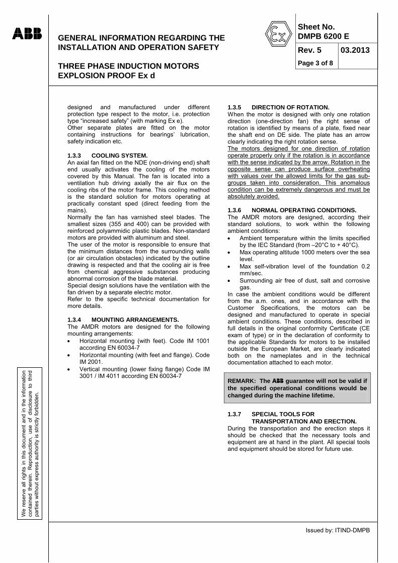
designed and manufactured under different protection type respect to the motor, i.e. protection type “increased safety” (with marking Ex e). Other separate plates are fitted on the motor containing instructions for bearings’ lubrication, safety indication etc. 1.3.3 COOLING SYSTEM. An axial fan fitted on the NDE (non-driving end) shaft end usually activates the cooling of the motors covered by this Manual. The fan is located into a ventilation hub driving axially the air flux on the cooling ribs of the motor frame. This cooling method is the standard solution for motors operating at practically constant sped (direct feeding from the mains). Normally the fan has varnished steel blades. The smallest sizes (355 and 400) can be provided with reinforced polyammidic plastic blades. Non-standard motors are provided with aluminum and steel. The user of the motor is responsible to ensure that the minimum distances from the surrounding walls (or air circulation obstacles) indicated by the outline drawing is respected and that the cooling air is free from chemical aggressive substances producing abnormal corrosion of the blade material. Special design solutions have the ventilation with the fan driven by a separate electric motor. Refer to the specific technical documentation for more details. 1.3.4 MOUNTING ARRANGEMENTS. The AMDR motors are designed for the following mounting arrangements: • Horizontal mounting (with feet). Code IM 1001
according EN 60034-7 • Horizontal mounting (with feet and flange). Code
IM 2001. • Vertical mounting (lower fixing flange) Code IM
3001 / IM 4011 according EN 60034-7
1.3.5 DIRECTION OF ROTATION. When the motor is designed with only one rotation direction (one-direction fan) the right sense of rotation is identified by means of a plate, fixed near the shaft end on DE side. The plate has an arrow clearly indicating the right rotation sense. The motors designed for one direction of rotation operate properly only if the rotation is in accordance with the sense indicated by the arrow. Rotation in the opposite sense can produce surface overheating with values over the allowed limits for the gas sub-groups taken into consideration. This anomalous condition can be extremely dangerous and must be absolutely avoided. 1.3.6 NORMAL OPERATING CONDITIONS. The AMDR motors are designed, according their standard solutions, to work within the following ambient conditions: • Ambient temperature within the limits specified
by the IEC Standard (from –20°C to + 40°C). • Max operating altitude 1000 meters over the sea
level. • Max self-vibration level of the foundation 0.2
mm/sec. • Surrounding air free of dust, salt and corrosive
gas. In case the ambient conditions would be different from the a.m. ones, and in accordance with the Customer Specifications, the motors can be designed and manufactured to operate in special ambient conditions. These conditions, described in full details in the original conformity Certificate (CE exam of type) or in the declaration of conformity to the applicable Standards for motors to be installed outside the European Market, are clearly indicated both on the nameplates and in the technical documentation attached to each motor.
REMARK: The guarantee will not be valid if the specified operational conditions would be changed during the machine lifetime.
1.3.7 SPECIAL TOOLS FOR
TRANSPORTATION AND ERECTION. During the transportation and the erection steps it should be checked that the necessary tools and equipment are at hand in the plant. All special tools and equipment should be stored for future use.

GENERAL INFORMATION REGARDING THE INSTALLATION AND OPERATION SAFETY
THREE PHASE INDUCTION MOTORS EXPLOSION PROOF Ex d
Issued by: ITIND-DMPB
Sheet No. DMPB 6200 E Rev. 5 03.2013 Page 4 of 8
We
rese
rve
all r
ight
s in
this
doc
umen
t and
in th
e in
form
atio
n co
ntai
ned
ther
ein.
Rep
rodu
ctio
n, u
se o
f di
sclo
sure
to
third
pa
rties
with
out e
xpre
ss a
utho
rity
is s
trict
ly fo
rbid
den.
1.4 SAFETY SPECIFIC INSTRUCTIONS.
1.4.1 COMMISSIONING AND OPERATING
SAFETY FOR HIGH AND MEDIUM VOLTAGE MACHINES (Vnom ≥ 1000 Volt).
1.4.1.1 GENERAL. Transportation, electrical and mechanical connections, commissioning and maintenance shall be carried out by expert and qualified personnel, as specified in the following paragraphs. The personnel shall have the characteristics required to be fully responsible, within their specified attributions, of the job done (in accordance to the requirements of EN 60079-14, EN 60079-17, EN 50110-1, VDE 0105, IEC 60364 Standards). Improper use or handling can cause serious dangers for the surrounding people or properties. All the necessary precautions regarding the safety at work shall be taken remembering that the motors in operation present zones under voltage, have high torque rotating parts and occasionally hot surfaces. 1.4.1.2 OPERATION. The motors covered by this Manual are intended for use in industrial installations. The general operating and functional characteristics are in accordance with the requirements of the harmonized series of motors described by the EN 60034 (VDE 0530) Standard. In particular the electromechanical design is conceived for operation within plants’ areas where a potentially explosive gas atmosphere can be present. In accordance with the a.m. characteristic, the subject motors are classified as electrical construction belonging to the Group II in accordance with EN 60079-0 Standard, intended for use in surface plant (with prohibition of use in mines). The ensemble of frame + endshields + bearings’ seals + cable entries, in other words the enclosure of the motor, is classified as degree of protection explosion-proof “d”. The motors covered by this Manual can be installed, in accordance with the EN 60079-14 Standard, in industrial areas classified as “Zone 1” (area in which an explosive gas atmosphere is likely to occur during the normal operation) and, obviously, in “Zone 2” (area in which an explosive gas atmosphere does not normally exist, but with possibility of presence in case of abnormal operation). For more details regarding the definition of the “Zones” see the EN 60079-10 Standard. The design and the following verifications done by the “Notified Labs” classifies the motors’ enclosures covered by this Manual within the “Group II C”. The
actual surface temperatures are guaranteed lower than the limits of the “Class T4”, in accordance with the EN 60079-0 Standard. Look at the nameplate and at the additional marking in case of special design.
The installer and the user of these motors are responsible for the compliance of installation areas with the a.m. definitions.
The terminal boxes can be designed and manufactured both as explosion-proof enclosures “d”, with classification Group IIC and Temperature Class T4, or as increased safety enclosures “e”. Look at the nameplates, additional markings and instruction manuals to check the protection modes and to identify special case, if any. Within the temperature limits specified in the Par. 1.3.6 the mechanical strength of the enclosure and the T4 limits for the surface temperatures are guaranteed and verified. Look at the nameplate and the specific Instruction Manual to check for special characteristics and motors’ design provided for operation in ambient temperatures outside the a.m. limits. 1.4.1.3 TRANSPORTATION AND STORAGE. We recommend to carry out an accurate inspection of the motors when they reach the installation site, in order to discover any possible damages. In case any damages (occurred after the factory delivery) would arise, notify immediately the problem to the Body responsible for the transportation and draw up, together with a representative of this Body (if possible), a detailed report. In case of suspected internal damage stop any commissioning operation. The lifting ring hooks are dimensioned for the weight of the motor, so do not apply additional loads. Fully screw the threaded shank of the ring hooks (if any) before any lifting movement. If necessary, suitable and adequately dimensioned means of transport (i.e. rope guides) can be used, providing their proper fixation and operation. Remove the shaft-locking device and other devices provided for the transportation safe before the commissioning. Store them for reuse in case of further movements. When the motors are stored, make sure that the storing area is dry, dust-free and that the vibration self-level of the storing basement is less than 0.2 mm/sec (Vrms) to avoid possible damages of the bearings. Measure the insulation resistance of the stator winding before the first run using instrumentation having output voltage between 500 and 2500 Volt d.c.

GENERAL INFORMATION REGARDING THE INSTALLATION AND OPERATION SAFETY
THREE PHASE INDUCTION MOTORS EXPLOSION PROOF Ex d
Issued by: ITIND-DMPB
Sheet No. DMPB 6200 E Rev. 5 03.2013 Page 5 of 8
We
rese
rve
all r
ight
s in
this
doc
umen
t and
in th
e in
form
atio
n co
ntai
ned
ther
ein.
Rep
rodu
ctio
n, u
se o
f di
sclo
sure
to
third
pa
rties
with
out e
xpre
ss a
utho
rity
is s
trict
ly fo
rbid
den.
If the measurement gives value of Rinsul. ≤ 1 kΩ per Volt of rated voltage, proceed with drying the windings. Refer to the relevant Chapters of this Manual for measuring methods and the suggested techniques for drying. 1.4.1.4 INSTALLATION. The installation on site of the motors shall be done in accordance with the requirements of the EN 60079-14 Standard.
REMARK! The personnel in charge with the final checks and the formal authorization for putting the machines into service and with the operation on the plants in areas where a gas explosion danger can exist must be skilled and qualified. The a.m. personnel shall have sufficient knowledge of the applicable Acts, Rules and Standards and of the general principles regarding the hazardous area classification; moreover they shall have attended specific training regarding the required protection modes and the installation techniques.
Make sure of even base supporting surfaces, solid foot or flange mountings and of the exact alignment in case of direct coupling with the driven machine, in accordance with the recommendations of this Manual (see the relevant Chapter). The responsibility of design and construction for the support foundation of the motors lies on the civil engineer in charge. Avoid that the supporting system can have mechanical resonance with the rotational frequency and the double of the mains’ frequency. The dowel pins (if any) shall be positioned on the basement only after the good result of the alignment operation.
REMARK! Basement must always be provided with dowel pins to avoid horizontal movements.
Turn the rotor by hand and listen for abnormal slipping noise. With the motor uncoupled from the driven machine check correct direction of rotation (see also the “electrical wiring” par.). During the assembly and disassembly of the coupling joint (or other driving components) carefully follow the Manufacturer instructions. All the rotating parts must be covered and protected against accidental contacts. Avoid excessive axial and radial loads on the bearings. The balancing of the rotating bodies is always done with an “half key”, so the coupling joint has to be balanced with the “half key” too.
Make sure of the right shape and dimensions of the ventilation channels, if any. For vertical motors the installer and the user must verify that the provided upper protection of the air intake is sufficient to assure the protection from foreign objects that can fall into the fan hub. The air intake shall be fully free and it is important to verify that the a.m. air intake doesn’t suck the hot air coming from the motor itself or from the exhausting of near apparatuses. 1.4.1.5 ELECTRICAL WIRING.
REMARK! The personnel in charge with the electrical wiring of components installed in areas where a gas explosion danger can exist must be skilled and qualified. The a.m. personnel shall have sufficient knowledge about the applicable Acts, Rules and Standards and of the general principles regarding the hazardous areas classification; moreover they shall have attended specific training regarding the required protection modes and the electrical wiring techniques in hazardous areas.
All the electrical wiring of the main feeding circuit of the motor shall be done with the motor stopped. Due to the electrical wiring of the main feeding circuit that involves medium or high voltage, the following safety rules must be taken: • Make absolutely sure that the feeding system is
out of voltage! • Provide safeguard devices against reclosing of
the breakers! • Verify safety distance and limits for the electrical
insulation from the mains! • Connect to hearth and short-circuit the cables
on which the job is in progress! • Cover or provide safety barriers against the
neighboring live electrical circuit!

GENERAL INFORMATION REGARDING THE INSTALLATION AND OPERATION SAFETY
THREE PHASE INDUCTION MOTORS EXPLOSION PROOF Ex d
Issued by: ITIND-DMPB
Sheet No. DMPB 6200 E Rev. 5 03.2013 Page 6 of 8
We
rese
rve
all r
ight
s in
this
doc
umen
t and
in th
e in
form
atio
n co
ntai
ned
ther
ein.
Rep
rodu
ctio
n, u
se o
f di
sclo
sure
to
third
pa
rties
with
out e
xpre
ss a
utho
rity
is s
trict
ly fo
rbid
den.
Make sure that even the auxiliary circuits (i.e. the internal space heaters) are surely out of voltage. The motors’ body and all the accessories shall be connected to earth, in accordance with the relevant Standard. On the frame and on the terminal boxes suitable earthing connection points are provided. Consult the drawings of the specific technical documentation attached to this Manual and the marking of the terminals for correct electrical wiring. Look at the connection indication fixed inside the terminal boxes. The cables’ inputs into the terminal boxes must be done using the certified cable glands provided with the motors and reported on the drawings. Make sure that the cable inputs have done respecting the suitable mechanical protection degree (IP ….) reported on the nameplate.
If it would be necessary to use different type of cable glands devices, it is compulsory that the used cable glands are of certified type “Ex d” o “Ex e” depending from the type of protection reported in the nameplate and that the cable glands are fixed to the terminal boxes respecting the requirements of the European Standard. The responsibility of use and assembling the proper cable glands lies always on the installer of the motor.
The terminals’ connections must be done with suitable components and methods and must assure permanent and safe contacts, even under severe operational conditions. If type of protection “e” (increase safety) is provided for the terminal boxes, make sure that the distances in air between the bare living conductors and the frame or metallic parts connected to earth were higher than the minim following limits:
Vnom ≤ 3300 Volt → 45 mm
3300 Volt< Vnom = 6600 Volt → 90 mm 6600 Volt< Vnom = 11000 Volt → 140 mm
Look at the EN 60079-7 Standard for intermediate values. Verify all the openings of the terminal boxes not engaged by cable glands; these openings must be closed with explosion proof plugs “Ex d” certified.
Make sure that the inside of the terminal boxes is free from moisture, dirt or foreign bodies. Before the reassembling of the covers for the explosion proof terminal boxes (type of protection “d”) verify that the machined surfaces are perfectly clean and without deformations or scratches. Lightly smear the joining surfaces with grease suitable to avoid their corrosion. During the trial runs with motor uncoupled from the driven machine provide a safe locking of the shaft key. In case a brake device would be provided, check its good operation before putting the motor into service. When the motor is fed by a frequency converter (inverter), in addition to the specific instructions contained in the relevant Manuals, it is necessary to ensure that the metallic structures of the motor and of the driven equipment are put at the same earth potential even in presence of the high frequency components of current and voltage generated by the inverter. This condition is satisfied when all the components of the shaft line are fixed on the same metallic basement. When this is not the case all the external metallic structures of the shaft line components shall be connected together with a flat copper conductor having cross section 0.75x70 mm ore more, providing that the ratio width/height of the section is more than 10. It is also possible to use two circular cables having minimum cross section of 50 sq-mm placed at 150 mm of distance between them. In case any special accessory was provided, check its good operation before the commissioning. The correct and safe installation of the electrical wiring (i.e. the separation of the power and signal lines, the screenings of the cables etc.) is under the responsibility of the installer. 1.4.1.6 OPERATION. During the operation of the motor the tolerances specified by the EN 60034-1 ( IEC 60034-1, VDE 0530) standards, must be respected: • Feeding voltage within ± 5% of the rated value. • Feeding frequency within ± 2% of the rated
value. • Feeding voltage having sinusoidal wave-shape
with the tolerances of the Standards. • Feeding three-phase system with symmetry
within the tolerances of the Standards.

GENERAL INFORMATION REGARDING THE INSTALLATION AND OPERATION SAFETY
THREE PHASE INDUCTION MOTORS EXPLOSION PROOF Ex d
Issued by: ITIND-DMPB
Sheet No. DMPB 6200 E Rev. 5 03.2013 Page 7 of 8
We
rese
rve
all r
ight
s in
this
doc
umen
t and
in th
e in
form
atio
n co
ntai
ned
ther
ein.
Rep
rodu
ctio
n, u
se o
f di
sclo
sure
to
third
pa
rties
with
out e
xpre
ss a
utho
rity
is s
trict
ly fo
rbid
den.
Operation outside the a.m. limits, if not expressly allowed and clearly reported on the nameplate, can result in surface temperatures exceeding the limits of the T4 temperature class and in alteration of the electromagnetic compatibility condition of the motor. The allowable maximum number of sequential starting is declared in the motor specific technical documentation. A new starting sequence is allowed only after the motor has cooled to the ambient temperature (for cold starts) or to the operating temperature (for warm starts). If abnormal situations or functional parameters outside the fixed limits (high temperatures, abnormal noise, and high vibration levels) would be detected, and if the total safety of the motor operation is in doubt, it is suggested to stop the motor. Under these circumstances the identification of the problem cause is a must; if necessary the manufacturing plant of the motor or a qualified Service organization can be consulted. In no circumstance the calibration of the protection devices has to be modified, even during the trial runs. The vibration level of the motor coupled with the driven machine shall be less than 4.5 mm/sec (Vrmms), which is the limit of the “allowed” field according ISO 10816 Standard. The motors covered by this Manual are characterized by a reduced distance between the static and rotating components in correspondence of the flame seals of the shaft; operation with vibration level within the “tolerable” field according the ISO 10816 Standard is absolutely not suggested. The ventilation channels and the frame fins shall be always clean; inspection at regular time interval shall be scheduled. If the motor is provided with drain plugs, they shall be opened, inspected for cleanness and tightness and reclosed. The regreasing of the antifriction bearings shall be made taking care of the prescribed regreasing intervals reported on the motor’s plates; the regreasing shall be made with the motor running. The proper grease type shall always be used. To evaluate the noise level emitted by the motor during the operation refer to the documentation; can give information on the choice and the use of additional devices (if necessary and requested) to decrease the noise level.
1.4.1.7 MAINTENANCE, OVERHAUL AND REPAIR.
REMARK! The personnel in charge with the maintenance and repair of the electrical equipment to be installed in areas where a gas explosion danger can exist must be skilled and qualified. The a.m. personnel shall have received a specific training on the technology of the a.m. equipment and have sufficient knowledge about the applicable Acts, Rules and Standards and of the general principles regarding the hazardous areas classification .
The verifications of the jobs carried out shall be in conformance with the requirements of the EN 60079-17 (IEC 60079-17) Standard. The repair techniques and the related checks shall respect the requirements of the “Standard for repair and overhaul of electrical equipment to be installed in potentially explosive atmosphere” (i.e. EN/IEC 60079-19). Always follow the instructions contained in the Instruction Manual and, in case of doubt; consult the motor’s Factory or an Service Factory. It is important to remember that the motors covered by this Manual can’t be modified in any way; this is compulsory for the components or subassemblies related to the protection mode or to the surface temperature (i.e. frame and endshields, covers, flame seals, input devices to the terminal boxes, winding etc.). When a substantial modification is absolutely necessary, the Standard requires a new homologation by a Notified Lab. For more details on this subject see the EN/IEC 60079-19 Standard. During the assembly and disassembly of the motors, carefully follow the instructions contained in the related paragraph of this Manual. Disassemble the different components with care and using the proper tools, to avoid any damage or deformation (even small) of the flame seals provided between the shaft and the bearings’ area. Verify with particular care all the flameproof joints and spigot surfaces machined with small rugosity, to be sure that no indents, scratches or deformations are present and that the surfaces are properly protected against oxidation. The entire machined surface shall be covered, before the assembly, with a slight smearing of silicon grease or special antifriction grease of the type indicated on the nameplates. Never use varnishes, adhesives, putting etc.

GENERAL INFORMATION REGARDING THE INSTALLATION AND OPERATION SAFETY
THREE PHASE INDUCTION MOTORS EXPLOSION PROOF Ex d
Issued by: ITIND-DMPB
Sheet No. DMPB 6200 E Rev. 5 03.2013 Page 8 of 8
We
rese
rve
all r
ight
s in
this
doc
umen
t and
in th
e in
form
atio
n co
ntai
ned
ther
ein.
Rep
rodu
ctio
n, u
se o
f di
sclo
sure
to
third
pa
rties
with
out e
xpre
ss a
utho
rity
is s
trict
ly fo
rbid
den.
When the threaded joining components (screws, bolts, nuts etc.) have to be replaced, make sure that their material and type were in conformance with the indication of the nameplates, that the proper elastic washer are used and that the length of their threaded shanks were as originally provided to guarantee the required minimum number of engaged threads. As a guide for the repair interventions, it is reported a table with the allowed or not allowed repairs or modifications of the various motor components.
Component Protection Remarks "d" "de"
Frame no no Endshields no no Bearing seals no no Main and auxiliary terminal boxes
no yes (1)
(1) Maintain the original mechanical integrity and IP protection
Insulators no no Thread on cables glands no yes
(2) (2) Maintain the original IP protection
Stator core no (3) no (3) (3) Only minor repairs allowed
Stator rewinding yes yes Rotor core yes
(4) yes (4)
(4) Check for overtemperature
Rotor cage yes (5)
yes (5)
(5) Check that the cage materials are the same of the original design
Shaft yes (6)
yes (6)
(6) With exclusion for the flame seals
Bearings no no Lubrication system yes yes Screws no (7) no (7) (7) Strength class
as the original design
Threaded holes no no(8) (8) The holes of the terminal boxes can be repaired
Fans no no Fan protection enclosures
yes (9)
yes (9)
(9) Check the minimum clearance between static and rotating parts
Gaskets no no Material and shape exactly as the original design
no = not allowed repair yes = allowed repair Any urgent intervention on a component having repair or modification marked as “operation not allowed” must be agreed in advance by factory from where the component comes from and the intervention must be authorized from that factory. The electrical machines with the mark “Ex…”, after a repair, must be always provided, under the responsibility of the repairer, with an additional and inerasable nameplate (further to the original nameplate) indicating: • The mark that the repair has left the machine in
full agreement with the relevant Standard and the original conformity Certificate.
• The identification of the Repairer. • The identification number of the repair job. • The date of the job execution. It must be remembered that the Acts of the European Community requires for that Countries the full correspondence to the original conformity Certificate. The Repairer, the Installer and the final User are solidly responsible of the full respect of the Standards and the Acts and Laws in charge within the installation Country. 1.5 REPORTING AND CONTROL SHEETS. In the following a set of "Control Sheets" is given. These sheets shall be used to record the data upon arrival of the motor on site, at assembly and at the commissioning. Even the ordinary periodic maintenance is covered. An accurate execution of the suggested jobs will ensure the maximum availability of the machine with a minimum of disturbance in the operation. It is very important that all the data obtained during the a.m. steps are recorded and maintained. In case of operation troubles, the right technical solution could be more easily obtained by the "Control Sheets" consultation, without time consuming investigations. The accurate and constant filling of the "Control Sheets" is therefore strongly suggested.

3PHASE INDUCTION MOTOR – FLAMEPROOF DESIGN Ex d - Group II B AMDR type – Size 355 ÷ 500 Inside view of the motor components Horizontal and vertical axis
Issued by: ITIND-DMPB
ABB Sheet No. DMPB 6231 E
Rev. 1 07.2007
Page 1 of 3
We
rese
rve
all r
ight
s in
this
doc
umen
t and
in th
e in
form
atio
n co
ntai
ned
ther
ein.
Rep
rodu
ctio
n, u
se o
f di
sclo
sure
to
third
pa
rties
with
out e
xpre
ss a
utho
rity
is s
trict
ly fo
rbid
den.
Variant with sleeve bearings
Horizontal axis – antifriction bearings

3PHASE INDUCTION MOTOR – FLAMEPROOF DESIGN Ex d - Group II B AMDR type – Size 355 ÷ 500 Inside view of the motor components Horizontal and vertical axis
Issued by: ITIND-DMPB
ABB Sheet No. DMPB 6231 E
Rev. 1 07.2007
Page 2 of 3
We
rese
rve
all r
ight
s in
this
doc
umen
t and
in th
e in
form
atio
n co
ntai
ned
ther
ein.
Rep
rodu
ctio
n, u
se o
f di
sclo
sure
to
third
pa
rties
with
out e
xpre
ss a
utho
rity
is s
trict
ly fo
rbid
den.
Vertical axis – antifriction bearings

3PHASE INDUCTION MOTOR – FLAMEPROOF DESIGN Ex d - Group II B AMDR type – Size 355 ÷ 500 Inside view of the motor components Horizontal and vertical axis
Issued by: ITIND-DMPB
ABB Sheet No. DMPB 6231 E
Rev. 1 07.2007
Page 3 of 3
We
rese
rve
all r
ight
s in
this
doc
umen
t and
in th
e in
form
atio
n co
ntai
ned
ther
ein.
Rep
rodu
ctio
n, u
se o
f di
sclo
sure
to
third
pa
rties
with
out e
xpre
ss a
utho
rity
is s
trict
ly fo
rbid
den.
The following table contains the indication of the main inside components of the motors , both with horizontal and vertical axis
Description of the main components of the motor 01 Stator magnetic core with winding 17 DE side snap ring 02 Complete rotor 18 DE side snap ring 03 Endshield DE side 19 Main line terminal box (Ex d IIC) 04 Endshield NDE side 20 Auxiliary terminal box (Ex d IIC) 05 External fan 21 Earth terminal 06 External fan cowling 22 Space heater 07 Antifriction bearing DE side 23 Bushing 08 Antifriction bearing NDE side 24 Additional auxiliary terminal box
(if required by the Order) 09 DE side inner flame seal 25 Sleeve bearing (DE and NDE sides) –
only horizontal axis 10 NDE side inner flame seal 26 Inner oil seal (DE and NDE sides) – only
horizontal axis 09a DE side inner flame seal. Labirinth type
for sleeve bearing. 27 Outer oil seal (DE and NDE sides) – only
horizontal axis 10a NDE side inner flame seal. Labirinth type
for sleeve bearing. 28 Bearing support box (DE and NDE
sides) – only horizontal axis 11 DE side external bearing closure 29 Protection canopy - only vertical axis 12 NDE side external bearing closure 13 DE side grease valve ring Cable glands Ex d for terminal boxes
entrances 14 NDE side grease valve ring Bearings’ temperature detectors (if
required by the Order) 15 DE side external rotating labirinth seal 16 NDE side external rotating labirinth seal = Spare parts advised. • Component order code definition: Example:
880300142.01/1 – 6231 - 03
Manufacturing order number (From motor data plate)
Manual page number Component number according to upper table

Transport and storage cares of Electrical Machines
Issued by: ITIND-DMPB
ABB Sheet No. DMPB 6172 E Rev. 2
Page 1 of 3
07.2003
We
rese
rve
al1
right
s in
this
doc
umen
t and
in th
e in
form
atio
n co
ntai
ned
ther
ein.
Rep
rodu
ctio
n, u
se o
f dis
clos
ure
to th
ird
parti
es w
ithou
t exp
ress
aut
horit
y is
stri
ctly
forb
idde
n.
Protective measures prior to transport To protect the bearings against damage during transport, the machines are provided with a shaft locking device, irrespective of the method of transport or distance. Antifriction bearings are normally filled with grease at the factory. Sleeve bearings are bathed in oil during the test before the delivery. This gives sufficient protection against corrosion for even the longest transport distances. Machined metal surfaces, such as shaft extension, are protected with an anticorrosive coating before delivery. Packing Depending on the Customer request and the transport conditions the machines can be delivered: • unpacked on a pallet • in a wooden box (sometime made with impregnated wood) • sealed within closed protective packing Sealed packing are used when the required transport and storage period in the country of destination exceeds 12 months. In contrast to the standard packing, the machine parts are completely enveloped in polyethylene wrappings the seams of which are welded to make an air-tight seal. All sharp corners and edges are padded to prevent the wrapping from being punctured. Check on arrival When the transport Company delivers the machine to the Customer, the responsibility for the handling passes to the Customer or designated other party. The machine shall be accurately inspected for completeness (including the accessories) and possible damages during transport, including the packing. If damages are detected these must be documented by photograph. Any transport damage must be reported within one week after arrival, if the transport insurance is to be claimed. It is therefore important that evidence of careless handling is checked and reported immediately to the transport company and the supplier. Indoor storage Machines with their associated accessories shall be stored in their original containers. Store rooms should be well-ventilated; the air should be free of corrosive gases and as dry and clean as possible. The relative humidity should possibly be kept below 50%. Heat the store rooms if necessary so that the temperature is about 10°C higher than that of the outside air. The size of the rooms should permit a safe and accessible storage arrangement. Take care
to protect the machines against possible insects such as termites and rodents. Check regularly the moisture content in the cases (if any). Pay attention to the carrying capacity of the floor. Do not stack heavy goods on top of each other. Always lay base frames, sole plates and similar parts absolutely flat to prevent distortion. The stored goods should not be overloaded by stacking. The cases should be so arranged that the case and component numbers could be clearly read off. Related parts should be stored in the sequence in which they are to be erected or according to the component numbers. Machines with rolling contact bearings are to be stored on vibration-free floors. If vibrations of the floor is present or may occur later (>0,2 mm/sec), the machine should be isolated by placing rubber blocks under the feet. The prolonged and continuos pressure of the rolling elements on their running surface can damage the bearings over a long storage period. To avoid this phenomena it is recommended to turn the machine rotor for some revolutions every six months of storage. To do this the shaft locking device has to be loosened. Take care during the retightening of the locking device to avoid possible axial loads on the bearings. The tightening torque for the fixing screws is 10 Nm max (7 lb-ft). In case the machine would be provided with sealed packing, this has to be locally opened and reclosed after the rotation of the shaft. Sleeve bearings do not require any shaft rotation during storage because the actual bearing surfaces will be dry i.e. the weight of the rotor will have pressed the oil film out from between the journal and the shell In case of very long (several years) storage it is recommended that the bearings will be opened according the dismantling instructions and that the journals and linings inspected before commissioning. In case “non contact” vibration probes should be provided, extreme care has to be taken for protection of the shaft machined surface under the probes. Outdoor storage If indoor storage is impossible, store the cases outdoors under cover of a weatherproof roof, or alternatively cover them with weatherproof tarpaulins. Tie down the tarpaulins. Do not lay the tarpaulins directly on the cases; keep them about 30 cm clear of the latter by draping them on laths or a wooden frame, thus leaving a space for ventilation. The cases should be protected against damp ground by placing them on battens or boards. A storage area should be selected which offers maximum protection against moisture (snow, floods), dirt, termites and
Transport and storage cares of Electrical Machines
Issued by: ITIND-DMPB
ABB Sheet No. DMPB 6172 E Rev. 2
Page 2 of 3
07.2003
We
rese
rve
al2
right
s in
this
doc
umen
t and
in th
e in
form
atio
n co
ntai
ned
ther
ein.
Rep
rodu
ctio
n, u
se o
f dis
clos
ure
to th
ird
parti
es w
ithou
t exp
ress
aut
horit
y is
stri
ctly
forb
idde
n.
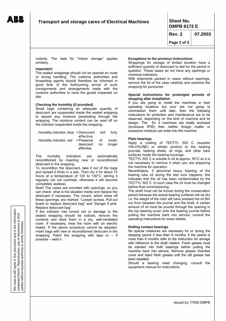
rodents. The data for “Indoor storage” applies similarly.
Important! The sealed wrappings should not be opened en route or during handling. The customs authorities and forwarding agents should therefore be informed in good time of the forthcoming arrival of such consignments and arrangements made with the customs authorities to have the goods inspected on site. Checking the humidity (if provided) Small bags containing an adequate quantity of desiccant are suspended inside the sealed wrapping to absorb any moisture penetrating through the wrapping. The moisture content can be read off on the indicator suspended inside the wrapping.
Humidity indicator, blue = Desiccant still fully effective.
Humidity indicator, red = Presence of moist, desiccant no longer effective.
The humidity indicators are automatically reconditioned by inserting new or reconditioned desiccant in the wrapping. To recondition the desiccant, take it out of the bags and spread it thinly in a pan. Then dry it for about 12 hours at a temperature of 120 to 130°C, stirring it regularly (do not overheat, otherwise it will become completely useless). Note! The cases are provided with openings, so you can check what is the situation inside and replace the desiccant if necessary. The covers, which close off these openings, are marked: “Loosen screws. Pull out board to replace desiccant bag" and “Danger if pink. Replace desiccant bag”. If the indicator has turned red or damage to the sealed wrapping should be noticed, remove the contents and store them in a dry, well-ventilated room. If necessary, heat the room with an electric heater. If the above procedure cannot be adopted, insert bags with new or reconditioned desiccant in the wrapping. Patch the wrapping with tape or – if possible – weld it.
Exceptions to the previous instructions Wrappings for storage of limited duration have a sufficient quantity of desiccant to last for the period in question. These cases do not have any openings or chemical indicators. With shipments packed in cases without openings, remove the lid of the case carefully and examine the wrapping for punctures. Special instructions for prolonged periods of stopping after installation If you are going to install the machines in their operating locations but your are not going to commission them until later, then the following instructions for protection and maintenance are to be observed, depending on the kind of machine and its design. The Ex d machines are totally enclosed (enclosure IP55) then neither foreign matter or excessive moisture can enter into the machine.
Plain bearings Apply a coating of TECTYL 502 C (supplier VALVOLINE) or similar product to the bearing journals, bearing shells, oil rings, and other bare surfaces inside the bearing housings. TECTYL 502 C is soluble in oil at approx. 50°C so it is not necessary to remove it when you are preparing the machine for operation. Nevertheless, if abnormal heavy foaming of the bearing lube oil during the test runs happens, this indicates that the oil has been contaminated by the TECTYL 502 C. In such case the oil must be changed before final commissioning. The shaft must not be turned during the conservation period because the actual bearing surfaces will be dry i.e. the weight of the rotor will have pressed the oil film out from between the journal and the shell. A certain amount of oil must be poured through the opening in the top bearing cover onto the bearing journal before putting the machine back into service; consult the operating instructions for exact details. Rolling contact bearings No special measures are necessary for or during the stopping period if less than 6 months; if the period is more than 6 months refer to the instruction for storage with reference to the shaft rotation. Fresh grease must be injected into both bearings before putting the machine back into service. Remove grease chamber cover and inject fresh grease until the old grease has been expelled. Should a bearing need changing, consult the equipment manual for instructions.

Transport and storage cares of Electrical Machines
Issued by: ITIND-DMPB
ABB Sheet No. DMPB 6172 E Rev. 2
Page 3 of 3
07.2003
We
rese
rve
al3
right
s in
this
doc
umen
t and
in th
e in
form
atio
n co
ntai
ned
ther
ein.
Rep
rodu
ctio
n, u
se o
f dis
clos
ure
to th
ird
parti
es w
ithou
t exp
ress
aut
horit
y is
stri
ctly
forb
idde
n.
Bare surfaces Apply a protective covering of TECTYL 506 (Supplier: VALVOLINE) or similar to all bare parts of the shaft outside the enclosure e.g. coupling, shaft surfaces, etc. Surfaces on the bedplate not covered by the motor feet or shims, and the edges of the shims themselves, are to be protected with paint as called for in the project specifications. In case “non contact” vibration probes should be provided, extreme care has to be taken for protection of the shaft machined surface under the probes, especially if the machine is installed outside. Remember that any corrosion on the machined surface under the probes will irreversibly damage the measuring system!
Piping The piping within the scope of the motor supply were cleaned, and dried by blowing through with warm air before packing. It must be ensured that they are still clean and dry before the machines are conserved.
Space heaters Space heaters must remain switched on in order to avoid condensation within the machine. Periodically check that they are operating. Openings If there are any openings where cables are not connected up to terminal boxes, or piping to flanges, etc. these are to be temporarily sealed up. Inspections, record The conservation measures are to be given a final check and recorded together with the date of the beginning of the conservation period. Thereafter carry out regular inspections, the first after six months and record results. Renew conservation measures when and where necessary. Preparing the machines for commissioning Restore machines to their original state (refer to check list below). Carry out through visual inspection of each machine and strictly follow instructions given in the operating manual. Keep full individual unit records of all work performed in preparing the machines for service. Such records can be of vital importance both to the commissioning engineer and to the user to enhance troublefree operation. Apply a protective layer of TECTYL 506 (supplier: VALVOLINE) or similar product on all the exposed bare surfaces, like the shaft expansion, the coupling etc.

INSTRUCTION FOR INSTALLATION, OPERATION AND MAINTENANCE Control list 1 General
ABB
Sheet No. DMPB 6223 E Rev. 0 Page 1 di 13 07.2003
use
of d
iscl
osur
e to
third
ith
out e
xpre
ss a
utho
rity
is s
trict
ly fo
rbid
den.
Customer Machine type Machine serial n°
Arrival date of the machine Signature of the consignee
DATE SIGNATURE Transport damage to motor and/or accessories Yes No (In case of damage use control list 2) Missing parts at delivery Yes No (In case of missing parts use control list 3) Motor storage period longer than 6 months Yes No (In case of long storage use control list 4) Mechanical installation: control list 5 Electrical installation: control list 6 Test run 1: control list 7 Test run 2: control list 8 Operational inspection: control list 9 Periodic maintenance: control list 10 Inside inspection: control list 11
Issued by: ITIND-DMPB
We
rese
rve
all r
ight
s in
this
doc
umen
t and
in th
e in
form
atio
n co
ntai
ned
ther
ein.
Rep
rodu
ctio
n,
parti
es w
Comments:
For record files To From Date Page Issued by Reg. n° Continues on page

INSTRUCTION FOR INSTALLATION, OPERATION AND MAINTENANCE Control list 2 Damages
ABB
Sheet No. DMPB 6223 E Rev. 0 Page 2 di 13 07.2003
use
of d
iscl
osur
e to
third
ith
out e
xpre
ss a
utho
rity
is s
trict
ly fo
rbid
den.
Customer Machine type Machine serial n°
Arrival date of the machine Signature of the consignee
Damages: Actions taken:
Machine Accessories Photographed Registered
Package Reported to Reported to supplier insurance Company
Other ............................................... Dispatched by To carrier
Railway Lorry/truck Airfreight Post/Mail Shipped by the m/s ............................. Other .........................................................
Issued by: ITIND-DMPB
We
rese
rve
all r
ight
s in
this
doc
umen
t and
in th
e in
form
atio
n co
ntai
ned
ther
ein.
Rep
rodu
ctio
n,
parti
es w
Damages found during customer inspection:
For record files To From Date Page Issued by Reg. n° Continues on page

INSTRUCTION FOR INSTALLATION, OPERATION AND MAINTENANCE Control list 3 Unpacking
ABB
Sheet No. DMPB 6223 E Rev. 0 Page 3 di 13 07.2003
use
of d
iscl
osur
e to
third
ith
out e
xpre
ss a
utho
rity
is s
trict
ly fo
rbid
den.
Customer Machine type Machine serial n°
Arrival date of the machine Signature of the consignee
Issued by: ITIND-DMPB
We
rese
rve
all r
ight
s in
this
doc
umen
t and
in th
e in
form
atio
n co
ntai
ned
ther
ein.
Rep
rodu
ctio
n,
parti
es w
Missing parts or comments: Check the list of parts while unpacking the motor. All damages, including those to the transportation package, should be photographed. Damages or mis- sing parts should be reported immediately to the forwarding agent, the insurance Company and to ABB. After unpacking, store parts and installation tools for future use. If no parts are missing at delivery, mark it on control list 1.
For record files To From Date Page Issued by Reg. n° Continues on page

INSTRUCTION FOR INSTALLATION, OPERATION AND MAINTENANCE Control list 4 Storage time longer than 6 months
ABB
Sheet No. DMPB 6223 E Rev. 0 Page 4 di 13 07.2003
use
of d
iscl
osur
e to
third
ith
out e
xpre
ss a
utho
rity
is s
trict
ly fo
rbid
den.
Customer Machine type Machine serial n°
Arrival date of the machine Signature of the consignee
Storage: Outdoors Indoors
In the packing case Protected by Warm Cool waterproof cover
Measures taken during storage:
Case is provided with External heating Space heaters ventilation openings is used are used
Bearings are lubricated Shaft end rust-proofing Absorbing material is checked material is used
Rotor is turned 10 revolutions Storage place is vibration free Air is free of every two months corrosive gases (only antifriction bearings) In case of machine idle for more than 6 months: - Repeat the conservation procedures - Insert another drying pack into the bearing In case of machine idle for more than 1 year: - Dismantle the sleeve bearings - Store and protect the sleeve bearings components linings.
Issued by: ITIND-DMPB
We
rese
rve
all r
ight
s in
this
doc
umen
t and
in th
e in
form
atio
n co
ntai
ned
ther
ein.
Rep
rodu
ctio
n,
parti
es w
Comments: Protective measures must be taken before operating the motor if stored for long period. The Customer is responsible for the storage and the required protective measures. The motor must be stored an a level surface in a vibration free area. If storage is outdoors, the motor must be protected against environmental effects. If long-time storage under humid conditions is anticipated, connection of space heaters, efficient coverage, and other protective measures must be arranged
For record files To From Date Page Issued by Reg. n° Continues on page

INSTRUCTION FOR INSTALLATION, OPERATION AND MAINTENANCE Control list 5 (1/2) Mechanical installation
ABB
Sheet No. DMPB 6223 E Rev. 0 Page 5 di 13 07.2003
use
of d
iscl
osur
e to
third
ith
out e
xpre
ss a
utho
rity
is s
trict
ly fo
rbid
den.
Customer Machine type Machine serial n°
Issued by: ITIND-DMPB
We
rese
rve
all r
ight
s in
this
doc
umen
t and
in th
e in
form
atio
n co
ntai
ned
ther
ein.
Rep
rodu
ctio
n,
parti
es w
Measures:
Foundation according to drawing ......................................... ……………………………
Alignment checked according to instructions
Foundation bolts tightened with torque wrench
Assembly of coupling half checked
Bearings filled with lubricant type - ................................ ……………………………
Bearings filled with lubricant quantity - ......................... ……………………………
Assembly of oil and coolant pipes checked. Flanges tightened
Stator terminal box mounted correctly Rotor rotates without scraping/sound (transport locking device dismantled)
Comments:
For record files To From Date Page Issued by Reg. n° Continues on page

INSTRUCTION FOR INSTALLATION, OPERATION AND MAINTENANCE Control list 5 (2/2) Mechanical installation
Issued by: ITIND-DMPB
ABB
Sheet No. DMPB 6223 E Rev. 0 Page 6 di 13 07.2003
We
rese
rve
all r
ight
s in
this
doc
umen
t and
in th
e in
form
atio
n co
ntai
ned
ther
ein.
Rep
rodu
ctio
n, u
se o
f dis
clos
ure
to th
ird
parti
es w
ithou
t exp
ress
aut
horit
y is
stri
ctly
forb
idde
n.
Customer Machine type Machine serial n°
Radial misalignment a1, b1, c1 and d1 are readings from the dial indicator "R" at the points a = top, b = bottom, c = right, d = left (4 turns, each of 90° angle). The readings are entered in the formula to obtain the values of radial misalignment (table 1).
Table 1 Measuring points
1st measurement
2nd measurement Example – measures in
Vertical hundredth of mm Top a1 a2 25 28
Bottom b1 b2 31 28
Difference a1-b1 a2-b2 -6 0
Vertical misalignment
a b2
1 1− a b2
2 2− -3 0
+ Left-hand coupling higher than the right-hand one Left-hand coupling - Left-hand coupling lower than the right-hand one raised by 0,03 mm. Horizontal Right c1 c2 38 28
Left d1 d2 18 28
Difference c1-d1 c2-d2 20 0
Horizontal misalignment
c d1 1
2− c d2 2
2−
10 0
+ Left-hand coupling displaced to right of the right-hand one Left-hand coupling - Left-hand coupling displaced to left of the right-hand one moved to left by 0,1 mm. Check for measuring error
a bc d
1 a bc d
1 1
1 1
2 2
2 2
++
= =++
25+31 1 28+2828+2838 18+
= = Schematic for table 1
Axial gap and misalignment The axial gap is determined by taking readings from the two dial indicators AI and AII, whereby the first reading from the top indicator AI is designated by e1 and that from the bottom indicator AII by h1. The values for vertical and horizontal gaps can be determined as shown in table 2 ; axial displacement (in the example 0.2 mm) during the measurement does not affect the results. Use a feeler gauge in case the gap is too small to use a dial gauge. Table 2
Measuring points Dial AI Dial AII Example – measures in Vertical gap hundredth of mm Top e1 g1 50 42
Bottom f1 h1 62 50 Gap
2)()( 1111 hgef −−−
2)5042()5062( −−−
+ The gap is greater at the top The gap is greater by - The gap is greater at the bottom 0,1 mm at the top. Horizontal gap Left i1 l1 40 36
Right k1 m1 48 40 Gap
2)()( 1111 mlik −−−
2)4036()4048( −−−
+ The gap is greater at the left The gap is greater by Schematic for table 2 - The gap is greater at the right 0,06 mm at the left.
For record files
To From Date Page Issued by Reg. n° Continues on page
top
Left-hand coupling
bottom
Direction of view
Right-hand coupling
right
left
Left-hand coupling
bottom
Direction of view
Right-hand coupling
top Right
Left
Left-hand coupling
bottom
Direction of view
Right-hand coupling

INSTRUCTION FOR INSTALLATION, OPERATION AND MAINTENANCE Control list 6 (1/2) Electrical installation
ABB
Sheet No. DMPB 6223 E Rev. 0 Page 7 di 13 07.2003
use
of d
iscl
osur
e to
third
ith
out e
xpre
ss a
utho
rity
is s
trict
ly fo
rbid
den.
Customer Machine type Machine serial n°
Issued by: ITIND-DMPB
We
rese
rve
all r
ight
s in
this
doc
umen
t and
in th
e in
form
atio
n co
ntai
ned
ther
ein.
Rep
rodu
ctio
n,
parti
es w
Safety:
The incoming cables are separated from the electric power network. The cables are grounded.
Electrical data: Electrical data: Machine Machine Voltage ......................... V/VAC Voltage ......................... V/VAC Frequency ......................... Hz Frequency ......................... Hz
Space heater ......................V/VAC, Space heater ......................V/VAC, External blower motor .…..................V/VAC, External blower motor .…..................V/VAC,
Insulation test:
Winding Rinsul. measured at..........…........ V/Vcc, Winding temperature ..........................°C
Rinsul. value (after 1 min) ….......................... MΩ, R insul. (40°C/104°F) = ................... MΩ
Rinsul. value (after 10 min)…........................ MΩ, R insul. (40°C/104°F) = ................... MΩ (See the section : "Winding maintenance of electrical machine") Main protection setting: Overcurrent level………….…................................. Overload level ….………….............................. Differential protection level ..........……………........ Ground fault level .......…………….............….. Negative sequence level ..............…………........... Acceleration time ....………………...............… Other protection level(s) .....……………………………………………………….……................................. The supply network is provided with: Under voltage protection, set at ......................................................................…..................................... Current transformers, ratio ................................................................................…................................... Voltage transformers, ratio ......................................................................................................................
For record files To From Date Page Issued by Reg. n° Continues on page

INSTRUCTION FOR INSTALLATION, OPERATION AND MAINTENANCE Control list 6 (2/2) Electrical installation
ABB
Sheet No. DMPB 6223 E Rev. 0 Page 8 di 13 07.2003
use
of d
iscl
osur
e to
third
ith
out e
xpre
ss a
utho
rity
is s
trict
ly fo
rbid
den.
Monitoring equipment Temperature monitoring Alarm (°C/F°) Trip (°C/F°) In stator winding In bearing In.......................................................
Issued by: ITIND-DMPB
We
rese
rve
all r
ight
s in
this
doc
umen
t and
in th
e in
form
atio
n co
ntai
ned
ther
ein.
Rep
rodu
ctio
n,
parti
es w
Flow or pressure monitoring: (m3/s o Pa) Alarm. Trip
(ft3/s o psi) Lubricating oil min. Lubricating oil max. Other Vibration: Comments:
For record files To From Date Page Issued by Reg. n° Continues on page

INSTRUCTION FOR INSTALLATION, OPERATION AND MAINTENANCE Control list 7 Test run 1
ABB
Sheet No. DMPB 6223 E Rev. 0 Page 9 di 13 07.2003
use
of d
iscl
osur
e to
third
ith
out e
xpre
ss a
utho
rity
is s
trict
ly fo
rbid
den.
Customer Machine type Machine serial n°
Date Name of supervisor
Connections:
Supply cables connected Auxiliary devices connected
Issued by: ITIND-DMPB
We
rese
rve
all r
ight
s in
this
doc
umen
t and
in th
e in
form
atio
n co
ntai
ned
ther
ein.
Rep
rodu
ctio
n,
parti
es w
First start Direction of rotation: clockwise counter-clockwise (as seen from drive-end) Noise: normal abnormal Second start (to full speed): Run: normal abnormal Noise normal abnormal Vibration: normal abnormal
Run OK operation stop (why?) ........................……………….......…. .................................................................................................................................................................. .................................................................................................................................................................. Time Bearing temp. Oil Comments: Stator
D-end N-end temp. (run, noise, vibration, etc.) Current Power (°C/°F) (°C/°F) (°C/°F) (A) factor Comments:
For record files To From Date Page Issued by Reg. n° Continues on page

INSTRUCTION FOR INSTALLATION, OPERATION AND MAINTENANCE Control list 8 Test run 2
ABB
Sheet No. DMPB 6223 E Rev. 0 Page 10 di 13 07.2003
use
of d
iscl
osur
e to
third
ith
out e
xpre
ss a
utho
rity
is s
trict
ly fo
rbid
den.
Customer Machine type Machine serial n°
Coupling connected On load Acceleration time:
Coupling disconnected At no load ..........................................
Issued by: ITIND-DMPB
We
rese
rve
all r
ight
s in
this
doc
umen
t and
in th
e in
form
atio
n co
ntai
ned
ther
ein.
Rep
rodu
ctio
n,
parti
es w
Time Bearing temp. Winding temperature Stator Vibration Load
or D-end N-end U / T1 V / T2 W / T3 Current Power (mm/sec-µm) (inch/sec-mils) (W)
date (°C/F°) (°C/F°) (°C/F°) (°C/F°) (°C/F°) (A) factor D-end N-end (HP) Comments:
For record files To From Date Page Issued by Reg. n° Continues on page

INSTRUCTION FOR INSTALLATION, OPERATION AND MAINTENANCE Control list 9 Operational inspection
ABB
Sheet No. DMPB 6223 E Rev. 0 Page 11 di 13 07.2003
use
of d
iscl
osur
e to
third
ith
out e
xpre
ss a
utho
rity
is s
trict
ly fo
rbid
den.
Customer Machine type Machine serial n°
Issued by: ITIND-DMPB
We
rese
rve
all r
ight
s in
this
doc
umen
t and
in th
e in
form
atio
n co
ntai
ned
ther
ein.
Rep
rodu
ctio
n,
parti
es w
Number of starts during week ......................................................................................... Operating hour during week ......................................................................................... Comments: Loggings of operational data and remarks should be kept for reference during maintenance work, trouble shooting and repairs. Year ............. , Week ............. Mon Tues Wed Thurs Fri Sat Sun Point of inspection Date Load (W/HP) Absorbed current (A) Fault indication (Yes/No) Bearing temp. D-end (°C) Bearing temp. N-end (°C) Oil level (Normal/Abnormal) Oil leakages (Yes/No) Winding temperature U/T1 (°C) Winding temperature V/T2 (°C) Winding temperature W/T3 (°C) Vibration level (Normal/Abnormal) Noise (Normal/Abnormal)
For record files To From Date Page Issued by Reg. n° Continues on page

INSTRUCTION FOR INSTALLATION, OPERATION AND MAINTENANCE Control list 10 Periodic maintenance
ABB
Sheet No. DMPB 6223 E Rev. 0 Page 12 di 13 07.2003
use
of d
iscl
osur
e to
third
ith
out e
xpre
ss a
utho
rity
is s
trict
ly fo
rbid
den.
Customer Machine type Machine serial n°
Issued by: ITIND-DMPB
We
rese
rve
all r
ight
s in
this
doc
umen
t and
in th
e in
form
atio
n co
ntai
ned
ther
ein.
Rep
rodu
ctio
n,
parti
es w
Maintenance interval …..............h, Operating hours ...........…..., Number of starts ..................... Bearings: Lubricant change Lubricant type .............................. Quantity .............................. Oil filter change Oil filter type .............................. Flanges and pipes checked Comments: Cooling: Cooling ribs cleaned Cooling tubes cleaned Air filter checked Cleaned External fan checked Comments: Electric components: Connection of high voltage cables checked Connection of control cables checked Space heater checked Machine opened and inspected Comments: Mechanical components: Coupling checked Foundation bolts checked Foundation checked Machine in general checked Machine opened and checked Bearings opened and checked Comments:
For record files To From Date Page Issued by Reg. n° Continues on page
INSTRUCTION FOR INSTALLATION, OPERATION AND MAINTENANCE Control list 11 Internal inspection
ABB
Sheet No. DMPB 6223 E Rev. 0 Page 13 di 13 07.2003
use
of d
iscl
osur
e to
third
ith
out e
xpre
ss a
utho
rity
is s
trict
ly fo
rbid
den.
Customer Machine type Machine serial n°
Issued by: ITIND-DMPB
We
rese
rve
all r
ight
s in
this
doc
umen
t and
in th
e in
form
atio
n co
ntai
ned
ther
ein.
Rep
rodu
ctio
n,
parti
es w
Annual inspection Type of duty : …………………………………………................ Inspection every 4 years Voltage : ………………Volt Current : …………........Amp Random inspection Load : ……………....kWatt Running hours : ……….….. 1) Bearings seals OK Observations : …………………………………… Grease injectors and grease outlet OK Observations : …………………………………… 2) Contaminations Stator Rotor Air passages Ends Remarks winding cage (tubes or ribs) D N Total amount of dirt Grease, oil Dry dirt, dust Dampness, rust 3) Inspection results OK Observations D N 3.1 Windings Supports Coils Connection cables 3.2 Stator core Core laminations 3.3 Rotor Rotor cage Cage bars ends Short circuit rings Core laminations 3.4 Inside fans 3.5 External fan Fan and hub Tubes or ribs 3.6 Electric connections Main line connections Bushings Control connections 3.7 Electrical tests
For record files To From Date Page Issued by Reg. n° Continues on page

Asynchronous motors explosion proof Ex d - Gas group IIB AMDR type - Size 355 - 500
Section 2
Installation, commissioning and
operation

FOUNDATIONS AND FASTENINGS EXPLOSION-PROOF THREE-PHASE INDUCTION MOTORS Ex d Horizontal Shaft Design
Issued by: ITIND-DMPB
Sheet No. DMPB 6182 E Rev. 4 Page 1 of 3
03.2013
We
rese
rve
all r
ight
s in
this
doc
umen
t and
in th
e in
form
atio
n co
ntai
ned
ther
ein.
Rep
rodu
ctio
n, u
se o
f dis
clos
ure
to th
ird
parti
es w
ithou
t exp
ress
aut
horit
y is
stri
ctly
forb
idde
n.
1. Fastening elements
The feet of the machine are provided with holes for the fastening bolts and with threaded holes for the leveling screws; dowel pins holes are sometime provided according to the design request. The fastening elements and the shims to adjust the center height are not usually supplied with the machine; look at the specific technical documentation for the required dimension of these elements. If the shims, the screws and the dowel pins (if any) are part of the order, they will be delivered as separate items.
2. Foundation
The responsibility for the design and construction of the foundation lies with the civil engineer commissioned for this work. Check prepared foundation and any ventilation ducts provided for conformity with the machine outline drawing and foundation plans and make any necessary correction. Foundations free from external vibration are recommended. The foundation (or the steel base fixed to the floor) must be strong and rigid, in order to avoid any resonance of the system with the force produced by the motor in normal and abnormal working condition. The installation of the motor (and of the driven machine) on a steel base having flexible pads requires special design considerations and is therefore a condition out of standard. The design for this special condition shall be clearly indicated on the outline drawing. Important! It is essential that the motor feet are supported along their full surface by the steel base or sole plates.
The foundation should be able to withstand sudden mechanical torque, which occurs at the machine starting or in case of abnormal conditions. The values of the stresses imposed on the foundation in normal and abnormal working condition are reported by the specific technical documentation. The upper level of the foundation or of the steel base shall permit a shimming of about 2 mm, but in any case not more than 4 mm (in order to avoid possible alteration of the mounting rigidity of the motor on the basement); this requirement is based on the shaft centre tolerance (that is +0 / - 1 mm respect the dimension indicated on the outline drawing) and makes easy the future installation of possible replacement machine.
Warning! The explosion proof motors have a very reduced backlash between the bearings anti-fire seals and the rotor shaft. For this reason it is necessary to pay attention during the installation of the machine on its foundations and in particular way during the regulation of the feet. It is necessary to verify that the foundation planes have an optimal planarity to avoid torsion deformations on motor chassis due to planarity errors, when the motor is fixed to the floor. After the machine has been aligned, shimmed and firmly secured to the base, a dial indicator micrometer oriented in the vertical direction shall be attached at the mounting foot to be checked. The micrometer is then zeroed the mounting bolt or bolts loosened at the foot and the change in micrometer reading noted. If the micrometer reading exceeds 0.05 mm (0.001 in), the mounting requires cleaning or re-shimming. This soft foot check shall be performed at each mounting foot, with the other feet secured, until all micrometer change readings are less than 0.05 mm (0.001 in). If there are intermediate bases, this check shall be performed at each interface between the machine and the floor.
3. Preparation for installation Prepare a set of steel sheet for shimming under the feet of the motor. Possible adjustments require shim thickness of 1 - 0.5 – 0.2 – 0.1 – 0.05 mm. It is necessary to have at site: • jacking for vertical positioning and screws or jacks
for axial and horizontal adjustments. • dial indicator gauges and related attachments to
achieve precise alignment within the specified tolerances (see relevant sheet).
• a set of leveling screw (see Fig. 1) and similar equipments.
4. Installing machines with bedplate (Fig. 1-3)
The following information describe the suggested method for installing the machines. Other methods (i.e. separate fixation of the bedplates) are possible. Bedplates, fastening bolts, anchor bolts and leveling elements are not usually supplied with the machine. If this elements are part of the order, they will be delivered as separate items.
4.1. The upper plane of the foundation must be clean (possibly vacuum cleaned). The walls of the grouting holes must have rough surface to allow a good grip. Presence of oil or grease must be removed by chipping away slices of the concrete surface.
4.2. Insert the greased leveling screws into the motor feet. Mount coupling hub to shaft extension. Wrap a

FOUNDATIONS AND FASTENINGS EXPLOSION-PROOF THREE-PHASE INDUCTION MOTORS Ex d Horizontal Shaft Design
Issued by: ITIND-DMPB
Sheet No. DMPB 6182 E Rev. 4 Page 2 of 3
03.2013
We
rese
rve
all r
ight
s in
this
doc
umen
t and
in th
e in
form
atio
n co
ntai
ned
ther
ein.
Rep
rodu
ctio
n, u
se o
f dis
clos
ure
to th
ird
parti
es w
ithou
t exp
ress
aut
horit
y is
stri
ctly
forb
idde
n.
layer of tape around the upper part of the anchor bolts (about 50 mm) to prevent this part from getting stuck in the concrete.
4.3. Fit the anchor bolts (5) or the through bolts (6) in the bedplates (1) so that the top of the anchor bolts is 1÷2 mm above the upper surface of the nuts (16).
4.4. Raise the machine, than hang the bedplates (together with anchor bolts) to the feet by means of the fastening bolts. Insert between bedplates and motor feet the suggested thickness of adjusting shims (2) and tighten the fastening bolts.
4.5. Determine the right location of the leveling elements (Fig. 1) and put them in place. Fix in place the leveling elements using preferably a bonding agent like Sikadur or similar. Put the machine with the bedplates on the leveling elements and adjust the level. The machine axis position must be approximately in accordance with the indication of the machine outline drawing.
4.6. Exactly align the motor to the coupling half of the mating machine by sliding it horizontally and adjusting vertically by means of the leveling screw.
5. Grouting guidelines
Site management is responsible for ensuring that the work is carried out in a proper and professional manner. Foundation and fastening components must be absolutely clean and unpainted. Never grout in parts which are oily or have been coated with normal paint.
5.1. Grouting in the foundation bolts (Fig. 2). Check again that the foundation surfaces is clean and wet. Fill the holes for foundation anchor bolts (5) with thin-bodied concrete up to approximately 10 mm below the top edge and vibrate if possible. Minimum setting time is 72 hours. After this period of time, the fastening nuts (16) may be tightened up. Care has to be taken when tightening up that neither the machine housing nor the sole plates or bedplates are distorted. After tightening, check again shaft alignment and correct if necessary.
5.2. Grouting in the foundation through bolts (Fig. 3). Fit anchor plates (8) and tighten up bolts. Care has to be taken when tightening up that neither the machine housing nor the sole plates or bedplates are distorted. After tightening, check again shaft alignment and correct if necessary. Dry foundation holes for bolts (6) and pack out with elastic filler (13) to 5-10 mm below top edge. recommend a granular synthetic filling compound, e.g. LUSTREX-Polystyrene 2220 or 4220. Supplier: MONSANTO PLASTICS & RESINS CO. 800 N. Lindbergh Blvd., St. Louis, No. 63166 (USA). Sand may not be used as a filler. After packing out with filler (13), seal top of foundation holes with an oil-resistive elastic sealing compound (14), e.g. with Sikaflex - 11 FC.
5.3. End of grouting. Finish grouting foundation in conformity with the corresponding outline drawing and foundation plan. Vibrate enclosed concrete (12).
5.4. Cast foundation plinth as close as possible to finished size (5-10 mm below top face of sole plate). Take care that the sole plates are completely filled with grout, tamping if necessary. (Mixture, pt. 5.5).
5.5. Concrete strength and mixture. Using concrete from a ready-mix concrete company subjected to quality control reduces risks in quality and should be procured if available. As a basic rule, higher standards of quality are to be set when ordering smaller quantities. One should try to attain a concrete strength B25 = 25 N/mm2.
5.6. If the services of a ready–mix concrete company are not available and in the absence of concrete mixture ratios, the figures given below may be taken as a guide. The concrete mixtures P300 and P350 are suitable for grouting machine foundations and contain 300 kg and 350 kg cement per 1 m3 of concrete, respectively. The sand and gravel proportions for 1 m3 of finished concrete are as follows:
40% Fine sand Grain size 0-5 mm 25% Coarse sand Grain size 6-15 mm 35% Gravel Grain size 16-35 mm 100-110 liters of water
The following mixture can be used for grouting the anchor bolt holes:
2/3 Fine sand Grain size 0-5 mm 1/3 Coarse sand Grain size 6-15 mm
When using any other mixtures, always cast and test a specimen block. Only clean, washed materials must be used. A high concrete strength will be attained with high standard strength of the cement, low water-cement ratio, and compacting by vibrating.
Water contents (I) Water-cement ratio = -------------------------------- Cement contents (kg)
The water-cement ratio has a decisive influence on the final strength of the concrete. It is desirable to have a water-cement ratio of 0.3 to 0.45, whereby the water contents of the aggregates must be taken into consideration. It is not permitted to have a water-cement ratio > 0.6. The concrete shall neither dry out nor freeze during the first 48 hours. During this time the temperature of the foundation should not fall below 10°C. The

FOUNDATIONS AND FASTENINGS EXPLOSION-PROOF THREE-PHASE INDUCTION MOTORS Ex d Horizontal Shaft Design
Issued by: ITIND-DMPB
Sheet No. DMPB 6182 E Rev. 4 Page 3 of 3
03.2013
We
rese
rve
all r
ight
s in
this
doc
umen
t and
in th
e in
form
atio
n co
ntai
ned
ther
ein.
Rep
rodu
ctio
n, u
se o
f dis
clos
ure
to th
ird
parti
es w
ithou
t exp
ress
aut
horit
y is
stri
ctly
forb
idde
n.
optimum temperature for the setting process is 20°C ± 10°C. Under normal conditions the foundation can be statically loaded 3 days after casting.
6. Mounting the machine on steel base. In this case it is supposed that the steel frame (already properly fixed to the floor) is correctly aligned with the mating machine. Check the thread for inserting the fastening bolts and set down the motor. Align the motor with the leveling screws and the shims than tighten the bolts.
7. Test before coupling. A test run is suggested before the coupling halves of the joint to the mating machine is connected. Refer to the commissioning instruction.
Levelling spindle Sole plates/Bedplate with foundation
anchor bolts
Sole plates/Bedplate with foundation
through bolt
Fig. 1
Fig. 2
retighten
Fig. 3
1 Sole plate/bedplate 2 Shims 3 Fastening bolt 4 Dowel pin (if any) 5 Foundation anchor bolt 6 Foundation through bolt 7 Levelling element 8 Anchor plate 9 Slide plate 10 Synthetic bonding agent 11 Concrete foundation 12 Grouting 13 Synthetic filling comp. 14 Elastic sealing comp. 15 Counter nut 16 Fastening nut

MACHINE FOUNDATION AND MOUNTING Vertical mounting arrangements
ABB
Sheet No. DMPB 6183 E
Rev.1 Page 1 of 1
07.2003
e re
serv
e al
l rig
hts
in th
is d
ocum
ent a
nd in
the
info
rmat
ion
use
of d
iscl
osur
e to
third
ith
out e
xpre
ss a
utho
rity
is s
trict
ly fo
rbid
den.
Mounting arrangement The general rules for foundation and mountings are similar to the rules for horizontal mounting arrangement. See Sheet No DMPB 6182 E. In general vertical machine are mounted on a separately prepared steel foundation plate. Installation on a steel foundation plate Check fastening holes in steel foundation plate, clean seating surfaces, set down machine and align. Couple machine and bolt up in operating location. Tighten holding down bolts uniformly, working in opposite pairs. The machine must rest squarely on its fastening flange around the whole circumference. After the final checks dowel the motor on the steel plate.
1. Machine fastening flange 2. Steel foundation plate 3. Holding down bolt
Issued by: CH-UMW
W cont
aine
d th
erei
n. R
epro
duct
ion,
pa
rties
w

Coupling for cylindrical or conical shaft extensions with keyways Fitting and dismantling instructions for horizontal machines having plain or rolling contact bearings with axial shaft guidance
Issued by: ITIND-DMPB
ABB Sheet No. DMPB 6173 E Rev. 2 Page 1 of 2
07.2003
We
rese
rve
all r
ight
s in
this
doc
umen
t and
in th
e in
form
atio
n co
ntai
ned
ther
ein.
Rep
rodu
ctio
n, u
se o
f dis
clos
ure
to th
ird
parti
es w
ithou
t exp
ress
aut
horit
y is
stri
ctly
forb
idde
n.
Preliminary inspection Inspection of all functional parts and components is essential before fitting a coupling for the first time. The hub bore and shaft extension should be checked against the dimensions specified on the sketch or drawing. It should also be ensured that the keyways in the coupling and shaft extension are truly parallel. The machine rotor is balanced with a half-key. Coupling components should be balanced on a mandrel, with a half-key filling the keyway. General information The following are the most frequent causes of poorly seated coupling hubs: - Damage on the shaft, coupling or keyway
(indentations, burrs or pressure marks). - Non-parallelism of keyways causing jamming and
excessive lateral thrust on keys and keyways. - Key too high causing it to bear top load. - A key fitted in a tapered shaft extension affects the
function of the tapered shrink seat and should therefore be avoided. If a key is nevertheless fitted, the coupling seat must be more accurate than normal. This means not only maintaining all tolerances but also that the exact contact between shaft and hub mating surfaces must be verified with blue oil, keyways in both shaft and hub must be checked for absolute parallelism, and the slightest imperfections such as burrs or pressure marks must be absolutely avoided.
Fitting instructions Thoroughly clean and dry all mating surfaces. Never coat such surfaces with molybdenum disulphide (Molykote) or similar products. A thin coating of oil on the shaft extension and hub bore is to be recommended. In general, the coupling manufacturer’s instructions are valid for mounting and removing the coupling hubs. It is common practice to heat the coupling in order to increase (or make) the clearance between the two fitting parts. If the coupling is keyed there is a certain clearance between the coupling and the shaft extension, so heating the coupling up to 80°C (176°F) will be sufficient for an easy fitting. Cylindrical and conical couplings (without keyway) are always fitted with interference and must be heated for the assembling on the shaft end. Refer to the specific instruction of the manufacturer.
IMPORTANT! : the couplings assembled with interference must be “enlarged” in case of disassembling from the shaft end. The enlargement is usually obtained by injection of oil under high pressure in circumferential grooves connected to suitable small oil injection channels. It is very important to take care, during the coupling assembling, to avoid any incision or axial scratch, that would prevent the oil pressurisation. Remember that if the oil can’t be pressurised, the coupling removal become very difficult, and in some case impossible. The weight of a coupling hub can be considerable, therefore suitable lifting gear must be available. Axial clearance The values for permissible axial loading are given on the machine dimension drawing. The axial clearance in the coupling must be chosen large enough to accept shaft displacement from the coupled machine. Our machines are normally fitted with a guide bearing at the drive end. Thermal expansion can therefore act towards the non-drive end without loading the coupling. Disassembling instruction Removal of couplings with keyway. The removal of the coupling from the shaft end can be easily obtained with a pulling tool of suitable dimension. Remember to protect the shaft end, where there is the contact with the pulling device centre pivot, with suitable soft material (see point A).

Coupling for cylindrical or conical shaft extensions with keyways Fitting and dismantling instructions for horizontal machines having plain or rolling contact bearings with axial shaft guidance
Issued by: ITIND-DMPB
ABB Sheet No. DMPB 6173 E Rev. 2 Page 2 of 2
07.2003
We
rese
rve
all r
ight
s in
this
doc
umen
t and
in th
e in
form
atio
n co
ntai
ned
ther
ein.
Rep
rodu
ctio
n, u
se o
f dis
clos
ure
to th
ird
parti
es w
ithou
t exp
ress
aut
horit
y is
stri
ctly
forb
idde
n.
Removal of couplings fitted with interference. In this case a suitable device for injecting oil under high pressure (in the order of 1000 bar and more) is required, together with an hydraulic jack capable of generating a force in the order of 100 ton.
The detailed instruction for the whole operation are generally described in the instruction manual of the coupling, so we suggest to refer to this document. The main steps of the operation are here described for information.
The dismantling operation of a coupling provided for cylindrical shaft end consists mainly of the following steps: - Place the hydraulic jack between the shaft end
and the coupling (through suitable plate and rods) to exert an axial force between the shaft end and the inner surface of the coupling. In other words the force generated with the jack must push the coupling out of the shaft end.
- Sustain with a suitable crane the weight of the coupling to avoid that the coupling will load the shaft end and the fall of the coupling itself.
- Connect the high pressure device at the threaded hole provided for this purpose on the coupling.
- Inject the oil under pressure into the circumferential grooves of the coupling and rise the pressure of the oil, following the operational instructions, to the value indicated on the instruction manual. If the whole system is without oil leakages, the coupling diameter will gradually expand, and the oil will come out laterally after some time (about 15 minutes).
- Apply with the hydraulic jack the axial force between the coupling and the shaft end. The force required for the extraction is normally in the order of 50 tons.
- Take off the coupling in one continuos step, possibly without interruption, maintaining a constant pressure on the oil.
In case of coupling with two or more inner diameter refer carefully to the detailed instructions of the manufacturer.

ALIGNING WITH DRIVEN EQUIPMENT HORIZONTAL AND VERTICAL MACHINES
Issued by: ITIND-DMPB
ABBSheet No DMPB 6145 E
Rev. 3 12.2004
Page. 1 of 3
We
rese
rve
all r
ight
s in
this
doc
umen
t and
in th
e in
form
atio
n co
ntai
ned
ther
ein.
Rep
rodu
ctio
n, u
se o
f di
sclo
sure
to
third
pa
rties
with
out e
xpre
ss a
utho
rity
is s
trict
ly fo
rbid
den.
INSTRUCTION FOR ALIGNING COUPLINGS The aim of the instruction given in the following is to attain proper alignment of the shaft extension without angular or parallel mismatch. This requirement can be fulfilled, as far as practically possible, by careful and accurate workmanship. The alignment instructions are basically valid for both rigid and flexible couplings and for all kinds of driven equipment. As well known, the linear dimension of the metallic objects changes with the temperature. Therefore during the alignment at ambient temperature, the evaluation of the rotation centerline position at the working temperature is suggested so it can be decided how much radial displacement is to be set for the cold machine in order to have the ideal condition of zero misalignment at the expected operating temperatures. For steel structures, like the motor frame, the height rise of the rotational centre of the shaft can be calculated with the following formula Δh (mm) ≅ 10-5 x H(mm) x Δt(°C) where H = size of the motor (feet height) Δt = difference between the alignment and the working temperatures (about 30°C)
Remark: the formula is based upon the standard thermal expansion of the steel, say about 0,01 mm for meter and for centigrade degree of temperature difference. The same formula is applicable even for the driven machine. The driven machine manufacturer must, in any case, give the right calculated value. The relevant measurements require that the machine rotor can be turned. If a horizontal machine with plain bearings has been at standstill for a long period of time, then the oil film between the bearings shells and the shaft will have been pressed out by the weight of the rotor i.e. the bearings will be dry. Therefore, before turning the rotor, approximately 100 - 200 cm3 of oil must be manually fed into each bearing. This can be done through the openings in the top of the bearing housing. The oil should be poured in using a funnel. If the manufacturer has not given details for setting radial displacement on the cold machine, then the rule is that zero displacement should be set. ALIGNMENT The following must be observed when coupling two or more machines together. The coupling halves must be exactly aligned to each other, following the fundamental rule that the shaft train is to be exactly horizontal (or vertical for vertical machines). The shaft being coupled must naturally be exactly concentric to each other and the coupling end faces exactly parallel.
HORIZONTAL MACHINES WITH SLEEVE BEARINGS Motors with sleeve bearings allow a certain axial float of the shaft. It is very important to remember that the motor cannot withstand any axial force from the driving machine. All axial forces must be withstood by the driven machine. Than the coupling must be of limited axial float type in order to guarantee that the sides of the bearings do not go in contact with the shoulders of the shaft. The motors are designed for 6 mm of total axial float. The coupling has to be made with the rotor standing on its natural running centre. Consult the specific technical documentation to obtain the exact value of the distance between the coupling shoulder on the shaft and the red mark on the external seals of the DE side bearings. Axially move the motor until it is assured that continuos free axial movement is possible between the coupling halves to allow the thermal expansion of the shaft (without damaging the bearings) and the maintenance or the substitution of the coupling. INSTRUCTIONS FOR CHECKING ALIGNMENT Each alignment check is to be preceded by a run-out check on the coupling flanges. HORIZONTAL MACHINES Radial misalignment (Table 1) and angular misalignment (Table 2) in the vertical plane can be corrected on electrical machines by inserting shims under the machine feet. Refer also to the chapter “Machine foundations and mountings”. Lateral radial misalignment (Table 1) and lateral angular misalignment (Table 2) can be corrected on electrical machines by moving the machine in the lateral direction. VERTICAL MACHINES Radial misalignment (Table 1: vertical = lateral) can be corrected on electrical machines by moving the whole machines. If the flanges are provided with spigots, then the correction can be made on either of the two mating flanges. If flanges are not provided with spigots, correction can be made by moving the whole machine radially within the clearance allowed between the holes and the fastening bolts in the coupling flanges. Angular misalignment (Table 2: vertical = lateral) can be corrected by inserting shims between the flanges covering the greatest area of flange face as possible.

ALIGNING WITH DRIVEN EQUIPMENT HORIZONTAL AND VERTICAL MACHINES
Issued by: ITIND-DMPB
ABBSheet No DMPB 6145 E
Rev. 3 12.2004
Page. 2 of 3
We
rese
rve
all r
ight
s in
this
doc
umen
t and
in th
e in
form
atio
n co
ntai
ned
ther
ein.
Rep
rodu
ctio
n, u
se o
f di
sclo
sure
to
third
pa
rties
with
out e
xpre
ss a
utho
rity
is s
trict
ly fo
rbid
den.
DOWEL PINS INSERTION. When the motor design provides the dowels pins between the frame and the basement, the pins must be positioned and fixed. It is also good practice, in every case, to fix the axial and lateral position of the motor with jig locators. The dowel pins insertion shall be done after the positive result of the alignment operation and the check at "warm" condition, after the motor and the driven machine have reached their working steady state temperature.
BELT DRIVE Motors with belt drives are always equipped with cylindrical roller bearing at the D end. Do not exceed the design radial force indicated by the specific technical documentation. Make sure that the driving and the driven pulleys are correctly aligned.
Radial misalignment
a1, b1, c1, and d1, are readings from the dial indicator R at the locations a = top, b = bottom, c = right, d = left. The readings are entered in the formulas to obtain the values of radial misalignment (Table 1, Fig. 1).
Table 1 Measuring location 1st
Measurement. 2nd Measuremt
Example - measures in hundredth of mm
Vertical Top a1 a2 25 28
Bottom b1 b2 31 28
Difference a1-b1 a2-b2 -6 0
Half difference= misalignment
a b1 12−
a b2 22− -3 0
+ Left-hand coupling is higher than the right-h. one Left-hand coupling - Left-hand coupling is lower than the right-h. one raised by 0,03 mm Lateral Right c1 c2 38 28
Left d1 d2 18 28
Difference c1-d1 c2-d2 20 0
Half difference= Misalignment
c d1 12−
c d2 22− 10 0
+ Left-h. coupl. displaced to right of right-h. coupl Left-hand coupling - Left-h. coupl. displaced to left of right-h. coupl. Moved 0,1 mm to left Check for measuring error
a bc d
a bc d
1 11 1
1 2 22 2
++
= =++
282828281
18383125
++
==++ Fig 1
Schematic for Table 1
Radial misalignment of the two coupling halves must be read in the 4 position each of 90° at same distance.
Maximum permissible radial misalignment (vertical and lateral misalignment)
Rigid coupling …………………............................................... ..Δ r = ± 0,02 mm
Gear coupling …………………...................................................Δ r = ± 0,05 mm
Flexible coupling (e.g. rubber-bushed coupling).........................Δ r = ± 0,10 mm
top
bottom
direction of view
right
left
left-hand coupling
direction of view
right-handcoupling
bottom
left-hand coupling
right-handcoupling
Δ r

ALIGNING WITH DRIVEN EQUIPMENT HORIZONTAL AND VERTICAL MACHINES
Issued by: ITIND-DMPB
ABBSheet No DMPB 6145 E
Rev. 3 12.2004
Page. 3 of 3
We
rese
rve
all r
ight
s in
this
doc
umen
t and
in th
e in
form
atio
n co
ntai
ned
ther
ein.
Rep
rodu
ctio
n, u
se o
f di
sclo
sure
to
third
pa
rties
with
out e
xpre
ss a
utho
rity
is s
trict
ly fo
rbid
den.
Axial gap and misalignment
The axial gap is determined by taking readings from the two dial indicators A I and A II, whereby the first reading from the top indicator A I is designated by e1 and that from the bottom indicator A II by h1. The values for vertical and lateral misalignment can be determined as shown in Table 2; axial displacement (in example 0,2 mm) during the measurement does not affect the results (Fig. 2).
Table 2 Measuring location Dial AI Dial AII Example - measures Vertical Gap in hundredth of mm Top e1 g1 50 42
Bottom f1 h1 62 50
Gap ( ) ( )f e g h1 1 1 1
2− − − 10
2)5042()5062(=
−−−
+ The gap is greater at the top The gap is greater by - The gap is greater at the right 0,1 mm at the top. Lateral Gap Left i1 l1 40 36
Right k1 m1 48 40
Gap ( ) ( )k i l m1 1 1 1
2− − − 6
2)4036()4048(=
−−−
+ The gap is greater at the left The gap is greater by Fig. 2 - The gap is greater at the right 0,06 mm at the left. Schematic for Table 2
Radial misalignment of the two coupling halves must be read in the 4 position each of 90° at same distance. In the example it is assumed that an axial movement of the shaft of 0,2 mm took place during the measurement. Maximum permissible value of vertical and lateral gap:
Rigid coupling …………………................................................ Δ b = ± 0,02 mm Gear coupling ……………………………………………………… Δ b = ± 0,05 mm
Flexible coupling (e.g. rubber-bushed coupling)...........………. Δ b = ± 0,10 mm
Axial gap and misalignment The axial gap is determined by taking readings from the two dial indicators A I and A II, whereby the first reading from the top indicator A I is designated by e1 and that from the bottom indicator A II by h1. The values for vertical and lateral misalignment can be determined as shown in Table 2; a minimal axial displacement (in example 0,2 mm) during the measurement does not affect the results (Fig. 2). Axial displacement. There must be sufficient axial clearance between the two coupling halves to accept a thermal expansion of 1 to 2 mm from the machine shaft. Δa = 3 ± 1 mm, or in conformity with coupling manufacturer data.
top right
left
left-hand coupling
bottom
Direction of view
right-handcoupling
Δ b
Δ a

PREPARATION FOR COMMISSIONING THREE PHASE INDUCTION MOTORS EXPLOSION PROOF Ex d TYPE ELECTRIC STEPS
Issued by : ITIND-DMPB
ABB
Sheet No DMPB 6144 E
Rev. 3 07.2007
Page 1 of 3
We
rese
rve
all r
ight
s in
this
doc
umen
t and
in th
e in
form
atio
n co
ntai
ned
ther
ein.
Rep
rodu
ctio
n, u
se o
f di
sclo
sure
to
third
pa
rties
with
out e
xpre
ss a
utho
rity
is s
trict
ly fo
rbid
den.
EARTH CONNECTIONS Connect the machine frame, the terminal box and the associated equipment to the earth with cables of suitable section in order to avoid any harmful potential on the metallic external structure. Mark the machine and the terminal boxes with earth symbols according to the relevant national standards. AUXILIARY CIRCUITS Check the correct connections of all the auxiliary circuits. Terminals of auxiliary equipments which are normally under voltage when the motor is switched off (i.e. space heaters) are correspondingly labelled. WARNING! take all the necessary precaution working on circuits that can be under voltage. INSULATION RESISTANCE Before a medium voltage asynchronous motor is started up for the first time (or after a long period of standstill) the stator winding insulation shall be checked. The measured value of the insulation resistance provides information about the humidity and dirtiness of the insulation. Unsuitable transportation or storage conditions might subject the machine to extremely moist condition. If the minimum value of insulation resistance cannot be reached, a drying process must be considered. Insulation resistance measurement Measure the insulation resistance before connecting the feeding cables to the motor terminals. WARNING! before any measurement of Insulation Resistance be sure that no potentially explosive atmosphere is present in the ambient. The instruments for the insulation resistance measurement (Megger or similar) apply direct voltage between the winding under test and the metallic parts of the motor connected to earth; the resistance value shall be taken after one minute after the application of the voltage. The windings not under test and the temperature detectors must be connected to earth. Usually the stator three-phase winding is measured as a whole, but if the star point can be opened, the measurement can be done phase by phase. For safety reason, after the measurement the winding under test has to be immediately connected to earth.
The test voltage, according to the available instrument, is normally between 500 and 2500 Volt. The following criteria are valid: a) For low voltage machine, the test voltage is 500
Volt maximum. b) Equal values of insulation resistance are
obtained with test voltage between 500 and 2500 Volt.
Test voltage of 500 Volt is therefore suggested as a rule. Phase by phase measurement U V W Test instrument (Megger type) 500 Volt d.c. Complete winding measurement U V W Test instrument (Megger type) 500 Volt d.c. Minimum allowed values of insulation resistance For safe (human safe) starting of the motor, the minimum allowed value for the stator winding insulation resistance is:
R 1 min (20°C) = [ 3 x (1 + Un) ] MΩ
Un =nominal voltage of the motor in kV (line to line). This value is referred to the complete winding. One phase gives a value that is roughly double. New machines and machines with new and dry windings have normally insulation resistance values much higher. As a rule of thumb, the expected value for new windings, suggested for the commissioning, is
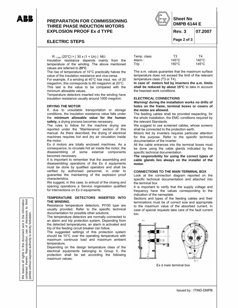
PREPARATION FOR COMMISSIONING THREE PHASE INDUCTION MOTORS EXPLOSION PROOF Ex d TYPE ELECTRIC STEPS
Issued by : ITIND-DMPB
ABB
Sheet No DMPB 6144 E
Rev. 3 07.2007
Page 2 of 3
We
rese
rve
all r
ight
s in
this
doc
umen
t and
in th
e in
form
atio
n co
ntai
ned
ther
ein.
Rep
rodu
ctio
n, u
se o
f di
sclo
sure
to
third
pa
rties
with
out e
xpre
ss a
utho
rity
is s
trict
ly fo
rbid
den.
R 1 min (20°C) > [ 30 x (1 + Un) ] MΩ Insulation resistance depends mainly from the temperature of the winding. The above mentioned values are referred to 20°C. The rise of temperature of 10°C practically halves the value of the insulation resistance and vice-versa. For example, if a winding at 40°C has insul. res. of 20 megaohm, this corresponds to 80 megaohm at 20°C. This last is the value to be compared with the minimum allowable values. Temperature detectors inserted into the winding have insulation resistance usually around 1000 megohm. DRYING THE MOTOR If, due to unsuitable transportation or storage conditions, the insulation resistance value falls under the minimum allowable value for the human safety, a drying process becomes necessary. The rules to follow for the machine drying are reported under the “Maintenance” section of this manual. As there described, the drying of electrical machines requires hot and dry air circulation inside the motor. Ex d motors are totally enclosed machines. As a consequence, to circulate hot air inside the motor, the disassembling of some external components becomes necessary. It is important to remember that the assembling and disassembling operations of the Ex d equipments must be done by qualified operators and shall be verified by authorised personnel, in order to guarantee the maintaining of the explosion proof characteristics. We suggest, in this case, to entrust of the closing and opening operations a Service organisation qualified for interventions on Ex d equipments. TEMPERATURE DETECTORS INSERTED INTO THE WINDING. Resistance temperature detectors, Pt100 type are usually provided. Refer to the specific technical documentation for possible other solutions. The temperature detectors are normally connected to an alarm and trip protection system. Depending from the detected temperatures, an alarm is activated and trip of the feeding circuit breaker can follow. The suggested settings of this protection system should be 10°C over the operating temperature with maximum continuos load and maximum ambient temperature. Depending on the design temperature class of the electrical equipments belonging to Group II, the protection shall be set according the following maximum values:
Temp. class T3 T4 Alarm : 145°C 140°C Trip : 150°C 145°C The a.m. values guarantee that the maximum surface temperature does not exceed the limit of the relevant temperature class (T3 or T4). In case of motors fed by inverters the a.m. limits shall be reduced by about 15°C to take in account the heaviest work conditions. ELECTRICAL CONNECTIONS Warning! during the installation works no drills of holes on the frame, terminal boxes or covers of the motor are allowed. The feeding cables shall be provided respecting, for the whole installation, the EMC conditions required by the relevant Standards. We suggest to use screened cables, whose screens shall be connected to the protection earth. Motors fed by inverters requires particular attention for this purpose. Refer to the specific technical documentation of the inverter. All the cable entrances into the terminal boxes must be done using the cable glands indicated by the specific technical documentation. The responsibility for using the correct types of cable glands lies always on the installer of the motor. CONNECTIONS TO THE MAIN TERMINAL BOX Look at the connection diagram reported on the specific technical documentation and attached into the terminal box. It is important to verify that the supply voltage and frequency have the values corresponding to the indication of the nameplate. Sections and types of the feeding cables and their terminations must be of correct size and appropriate to the maximum value of the absorbed current. In case of special requests take care of the fault current too.
Ex d main terminal box

PREPARATION FOR COMMISSIONING THREE PHASE INDUCTION MOTORS EXPLOSION PROOF Ex d TYPE ELECTRIC STEPS
Issued by : ITIND-DMPB
ABB
Sheet No DMPB 6144 E
Rev. 3 07.2007
Page 3 of 3
We
rese
rve
all r
ight
s in
this
doc
umen
t and
in th
e in
form
atio
n co
ntai
ned
ther
ein.
Rep
rodu
ctio
n, u
se o
f di
sclo
sure
to
third
pa
rties
with
out e
xpre
ss a
utho
rity
is s
trict
ly fo
rbid
den.
Ex e main terminal box The winding terminals (bushings) are marked with the letters U – V – W in accordance with IEC 60034-8 Standards. The neutral terminal, if any, is marked with the letter N. The connection with a feeding system having the correct phase sequence (L1 – L2 – L3) guarantees the right rotation sense of the shaft in accordance with the arrow put near the shaft on D.E. side. In case of wrong phase sequence, the rotation sense of the shaft con be inverted simply by the commutation of the connection to the U and W terminals. CONNECTION TO THE AUXILIARY TERMINAL BOX One or more auxiliary terminal boxes can be provided. The standard solution provides one auxiliary terminal box having a separator barrier between the terminals of the power circuits (space heaters, possible external fan etc.) and the measuring and protection system terminals. Make sure that all the monitoring instrument connections are properly wired in accordance with the electric diagram contained into the specific technical documentation and verify their proper operation. Warning! take all the necessary precaution working on circuits that can be under voltage.
Ex d IIB auxiliary terminal box
Ex d IIC auxiliary terminal box

PREPARATION FOR COMMISSIONING THREE PHASE INDUCTION MOTORS MECHANICAL STEPS
Issued by: ITIND-DMPB
ABB Sheet No. DMPB 6178 E Rev. 2 Page 1 of 2
07.2003
We
rese
rve
all
right
s in
thi
s do
cum
ent
and
in t
he i
nfor
mat
ion
cont
aine
d th
erei
n.
Rep
rodu
ctio
n,
use
of
disc
losu
re
to
third
pa
rties
with
out e
xpre
ss a
utho
rity
is s
trict
ly fo
rbid
den.
BEARINGS ANTIFRICTION BEARINGS (Rolling-contact bearings) The bearings are filled with lithium soap grease before delivery. Periods of standstill lasting some months, as for storage for instance, can result in oil separation from the bearing lubricating grease. Dismantle the outer bearing cover and, if this is the case, remove the grease and oil residue. Replace the removed grease with fresh grease of proper type and close again the bearing cover. Bearing temperature monitoring. If provided the temperature detectors shall be set at the lower possible temperature based on the test results and operating condition. The maximum values recommended for normal operating temperature with standard lubricants and ambient temp. at 40°C are: Alarm : 90°C (194°F) Trip : 100°C (212°F) If high temperature grease is used (i.e. for machines rated at class F working temperature) the a.m. limits can be set 10°C (28°F) higher. Refer to the specific technical documentation. SLEEVE BEARINGS Sleeve bearing machines are delivered without oil. On machines with self-cooled bearing, i.e. not having a separate oil supply system, the oil is carried to the bearing faces by oil rings. During longer shut-down periods the oil film between the bearing shell and the bearing journal will be pressed out by the weight of the rotor, i.e. the bearing will be dry! Therefore, prior to rotate the shaft (even by hand), at least 100 to 200 cm³ of oil must be introduced manually into each bearing. This can be done by removing the screw-plug or vent-filter located on top of the bearing cover and inserting a funnel into the exposed opening. Be sure to use the correct type of oil. When introducing the lube oil, only fill to the correct level i.e. up to the middle of the oil sight window. A higher oil level is not recommended as this could cause oil leakage at the seals during operation. Machines cooled by an axial external fan (HXR or AMDR-AMDT types) are
provided on N.D.E. side with a vent tube (with filter) coming out from the ventilation hub to avoid the pressurisation of the bearing enclosure. Separately cooled plain bearings. The bearings are connected to an oil supply system, which should be in operation before the machine is started up and remain in operation until the machine is turned down. The maximum oil inlet temperature of the bearings should not exceed 65°C. Bearing temperature monitoring. If provided the temperature detectors shall be set using the same criteria applicable for antifriction bearings. The maximum values recommended for normal operating temperature with standard lubricants and ambient temp. at 40°C are: Alarm : 90°C (194°F) Trip : 100°C (212°F) Laying the oil lines. Flexible pipe elements must be fitted between the connection pipe or flange on the motor and the oil supply lines to attain a tension-free connection. This ensures for better, oil-tight connection and also helps to avoid electrical insulating parts from being damaged, if such are fitted. Before fitting, the lines should be tapped gently to clear out scale, rust and sand, then washed out with inhibited hydrochloric acid and rinsed with rinsing oil. The inhibitor should be used to supplier’s instructions. The oil return line must have a continuous slope of 5% (= 50 mm per 1000 mm of length) from the connection flange on the motor bearing to the oil tank. This is the minimum permissible slope! Remember that the oil level of the bearings will increase if the oil moves too slowly in the discharge tubes. This can result in oil leaks or disturbance in the flows. On principle, oil return lines should be kept as short as possible. Their free cross-section should be at least as large as that of the outlet. Bends should be avoided where possible. To avoid risk of oil damming up or pressure build-up in the bearings, these lines should contain no double bends or siphons. Specifications on drawings have to be taken into account, where applicable. Inlet points have to be arranged in the direction of flow. Pipe sections must be large enough to obtain the following oil flow velocities: - Oil inlet (full pipe section) less than 1.5 m/sec. - Oil return (full pipe section) less than 0.17 m/sec. In order to suppress the formation of oil foaming, vertical drops > 1 m are to be avoided.
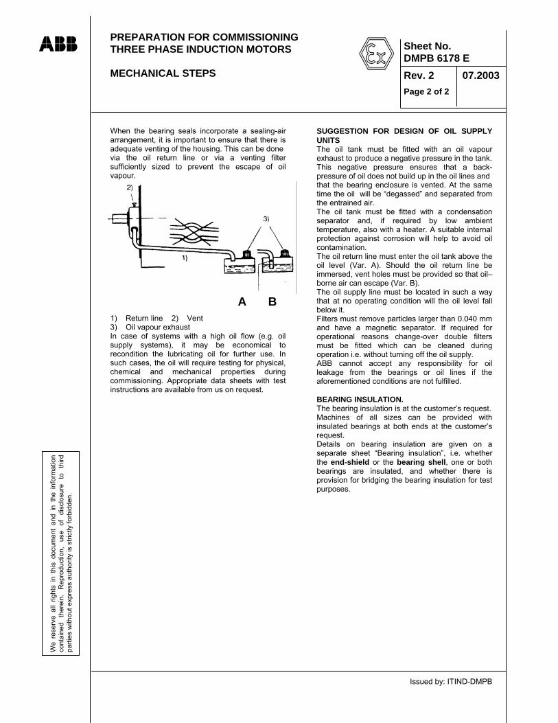
PREPARATION FOR COMMISSIONING THREE PHASE INDUCTION MOTORS MECHANICAL STEPS
Issued by: ITIND-DMPB
ABB Sheet No. DMPB 6178 E Rev. 2 Page 2 of 2
07.2003
We
rese
rve
all
right
s in
thi
s do
cum
ent
and
in t
he i
nfor
mat
ion
cont
aine
d th
erei
n.
Rep
rodu
ctio
n,
use
of
disc
losu
re
to
third
pa
rties
with
out e
xpre
ss a
utho
rity
is s
trict
ly fo
rbid
den.
When the bearing seals incorporate a sealing-air arrangement, it is important to ensure that there is adequate venting of the housing. This can be done via the oil return line or via a venting filter sufficiently sized to prevent the escape of oil vapour. 1) Return line 2) Vent 3) Oil vapour exhaust In case of systems with a high oil flow (e.g. oil supply systems), it may be economical to recondition the lubricating oil for further use. In such cases, the oil will require testing for physical, chemical and mechanical properties during commissioning. Appropriate data sheets with test instructions are available from us on request.
SUGGESTION FOR DESIGN OF OIL SUPPLY UNITS The oil tank must be fitted with an oil vapour exhaust to produce a negative pressure in the tank. This negative pressure ensures that a back-pressure of oil does not build up in the oil lines and that the bearing enclosure is vented. At the same time the oil will be “degassed” and separated from the entrained air. The oil tank must be fitted with a condensation separator and, if required by low ambient temperature, also with a heater. A suitable internal protection against corrosion will help to avoid oil contamination. The oil return line must enter the oil tank above the oil level (Var. A). Should the oil return line be immersed, vent holes must be provided so that oil–borne air can escape (Var. B). The oil supply line must be located in such a way that at no operating condition will the oil level fall below it. Filters must remove particles larger than 0.040 mm and have a magnetic separator. If required for operational reasons change-over double filters must be fitted which can be cleaned during operation i.e. without turning off the oil supply. ABB cannot accept any responsibility for oil leakage from the bearings or oil lines if the aforementioned conditions are not fulfilled. BEARING INSULATION. The bearing insulation is at the customer’s request. Machines of all sizes can be provided with insulated bearings at both ends at the customer’s request. Details on bearing insulation are given on a separate sheet “Bearing insulation”, i.e. whether the end-shield or the bearing shell, one or both bearings are insulated, and whether there is provision for bridging the bearing insulation for test purposes.
A B

FIRST STARTING AND SUPERVISION TO THE OPERATION THREE PHASE INDUCTION MOTORS Explosion proof Ex d types
Issued by: ITIND-DMPB
ABB W
e re
serv
e al
l rig
hts
in th
is d
ocum
ent a
nd in
the
info
rmat
ion
cont
aine
d th
erei
n. R
epro
duct
ion,
use
of d
iscl
osur
e to
third
pa
rties
with
out e
xpre
ss a
utho
rity
is s
trict
ly fo
rbid
den.
Sheet No. DMPB 6184 E Rev. 2 Page 1 of 2
06.2007
GENERAL The AMD motors are certified to a minimum ambient temperature of – 20 °C; if they are required to operate at lower ambient temperature, they must be heated to – 20 °C at least to recover the safety mechanical strength for the explosion withstanding. Motors operating at such very low ambient temperature are provided with the following types of space heaters:
1. anticondensation space heater (as for standard motors)
2. pre-heating space heaters before starting up
3. space heaters for terminal box heating: they are only provided in case that special equipments are fitted in the terminal box. Remark: it is shown on the relevant auxiliary wiring diagram when such special space heaters are in the scope of supply.
Regardless of the ambient temperature, the anti- condensation space heater shall be switched on when the motor is idle. If provided, the terminal box space heater shall be fed when the ambient temperature is lower than – 20°C.
FIRST STARTING Start-up at ambient temperature lower than –20 °C (-4°F) Remark: the following applies not only to the first start, but to the every subsequent starts of the motor when the ambient temeprature is below –20°C (-4°F) Switch on the pre-heating space heaters to ensure that the temperature inside the motor is – 20 °C at least. The time required to heat the motor is shown on the specific order documentation, otherwise, if RTD’s measuring the motor inner air temperature are provided (see the auxiliary wiring diagram), the motor start-up can be automatically set according to RTD’s measurement. Just before starting, all the space heaters must be switched off. Test start Before the first start-up of the motor check the correct insertion of the dowel pins (if any) between the frame feet and the basement. After all devices, except the coupling to the driven machine, have been connected proceed to the first starting.
The first start should last only about one second. Check that the direction of rotation is right and that there is no obstacle deterring the free running of the machine. In case of sleeve bearings, check that the stationary parts do not absolutely go in contact with the rotating parts. After this initial test, the machine can be started again and can be run for longer time. Check the temperature of the winding and the temperature and the correct lubrication of the bearings. In case of sleeve bearings check the oil level and the oil pressure. When all the a.m procedure have been made connect the coupling to the driven machine and proceed to the start of the complete shaft line. Check again and frequently the temperature of the winding and of the bearings. If sensors into the bearings are not provided measure the surface temperature in the bearing area. The bearing working temperature is approximately the surface temperature + 10°C (50°F). If the operation appears normal, the machine can be left running and can be loaded. Number of starts. The maximum number of starts-up in a day or year, and the maximum allowed number of sequential starts in cold or warm conditions is a typical data of the motor, depending on the design characteristics of the machine. Details and information about this subject are reported within the specific technical documentation. The motor standard design allows a maximum of 3 successive starts from cold condition or a maximum of 2 successive starts from warm condition (steady state temperature of the active parts at normal load). Refer to the specific technical documentation for possible different requirements. Remember that too frequent and too many starts accelerate the general ageing process of the active components and cause a reduction of the motor operating life. In particular too many successive starts results in high temperatures and dangerous mechanical stresses in the active parts of the machine.

FIRST STARTING AND SUPERVISION TO THE OPERATION THREE PHASE INDUCTION MOTORS Explosion proof Ex d types
Issued by: ITIND-DMPB
ABB W
e re
serv
e al
l rig
hts
in th
is d
ocum
ent a
nd in
the
info
rmat
ion
cont
aine
d th
erei
n. R
epro
duct
ion,
use
of d
iscl
osur
e to
third
pa
rties
with
out e
xpre
ss a
utho
rity
is s
trict
ly fo
rbid
den.
Sheet No. DMPB 6184 E Rev. 2 Page 2 of 2
06.2007
Important remark: Re-switching a running motor causes current and torque fluctuations. Reclosure at an instant when the system is in phase-opposition to the residual stator voltage will subject the motor and the driven machine to very high forces. This condition shall be avoided if the whole shaft train is not dimensioned by design to sustain these stresses.
Supervision and maintenance during the first start The machine load, the regular cooling, the operation of the bearings and the vibration level are essential factors for the operation of the machine and need to be checked regularly. During the first period of operation (24 hours), supervision should be intensive and the essential factors must be recorded at least every hour. It is suggested that these factors would be recorded on maintenance card or computer files. The temperature readings obtained by the sensors placed in the stator winding and possibly in the bearings need to be checked to ensure that they remain below the maximum allowed limits. Compare the absorbed current with the value given on the nameplate to check the operating condition of the machine. Motors with roller bearings (antifriction bearings) In case of newly installed machine or a machine which has been out of service for long time, inject new grease immediately after the start up. When the motor is running, make sure that the old grease and the excess new grease are discharged through the openings in the bottom of the bearings housing. The temperature of the bearings will initially increase because of the excess of grease. After few hours the excess grease will be discharged and the bearings’ temperature will return at normal values. Horizontal motors with sleeve bearings After the start-up check that there is no contact between stationary and rotating parts and that no abnormal noise is coming from the motor. Pay attention to the oil tightness of the tubes connections. It is recommended a bearing full inspection after a running on load for few hours or after substitution of bearings’ components. The rotation of the lubrication ring can be verified through the inspection hole on the top of the bearing housing. Check the temperature and the oil level frequently during the first hours of rotation. In case of oil feeding from outside equipment check the incoming oil pressure and the rate of oil flow. Refer to the specific technical documentation for the required value.
Vibration. Check the vibration level with a suitable portable instrument. The vibration probe can be fixed to the bearing housing or to the endshields. Compare the measured values to the values prescribed in the applicable Standards. In case of doubt or problem it is useful to analyze the frequency spectrum of the vibration signal. For the prescribed value see the Sheets "Maintenance of the bearings" of this manual. SUPERVISION OF THE OPERATION
The operating personnel shall inspect the machine frequently. The purpose of the inspection is also to familiarize personnel with the equipment. This is imperative to permit the detection and correction in time of possible abnormal occurrences. Check always before starting that no shut-down precaution or means have been forgotten (i.e. the standstill heating equipment) and that the lubrication and cooling means are functioning. The run inspections must cover the following points: Bearings: • bearing temperature • noise from the bearings • oil level or oil flow • absence of oil leakages • vibration Cooling: • temperature of the stator winding • normal flow of cooling air • cleanness of cooling air • surface temperatures
Remark: if the cooling air contains dust, clean regularly the cooling surfaces of the motor.
Miscellaneous: • noise • vibration level • indications of alarm or fault

OPERATING FAULTS Trouble shooting information for Squirrel Cage Induction motors.
Emesso da ITIND - DMPB
ABB Sheet No. DMPB 6230 E
Rev. 0 Page 1 of 8
07.2003
We
rese
rve
all r
ight
s in
this
doc
umen
t and
in th
e in
form
atio
n co
ntai
ned
ther
ein.
Rep
rodu
ctio
n, u
se o
f dis
clos
ure
to th
ird
parti
es w
ithou
t exp
ress
aut
horit
y is
stri
ctly
forb
idde
n.
Early identification of abnormal operation symptoms and rapid remedial action are essential as a means of preventing minor fault from developing into really serious trouble later on. The following trouble-shooting flow-charts may help you to trace and remedy possible faults. Always disconnect the motor from the mains before you attempt to trace a fault or attend to the stator switch. A) Faults at starting.
Motor emits normalmagnetic noise, but doesnot start under load
Check the supplytransformer
Feeding voltagetoo low
Uncouple the motorand check regularno load run
Motor hums but doesnot start
Motor does not start and no noise is emitted
One phase ismissing
No voltage onthe feeding line
Check supply leadsand repair break
Check mains supplyleads
Measure the supply voltage
no
yes
Excessive load torque
Remedy to theexcessive load torque

OPERATING FAULTS Trouble shooting information for Squirrel Cage Induction motors.
Emesso da ITIND - DMPB
ABB Sheet No. DMPB 6230 E
Rev. 0 Page 2 of 8
07.2003
We
rese
rve
all r
ight
s in
this
doc
umen
t and
in th
e in
form
atio
n co
ntai
ned
ther
ein.
Rep
rodu
ctio
n, u
se o
f dis
clos
ure
to th
ird
parti
es w
ithou
t exp
ress
aut
horit
y is
stri
ctly
forb
idde
n.
1) If the load inertia is larger than what has been reported, please contact the supplying ABB
Company. 2) Starting system can be star-delta connection, starting reactor or auto-transformer. When a
starting system different than the direct on line starting, the machine torque decrease and the starting time increase. This must be noticed.
3) Driven machines may have different starting methods. Many of them can be started without load. For example, compressors and blowers can be started with closed suction vanes. In many cases the driven machine feeding can be started after starting the motor. It is possible that the motor does not start loaded, if it has been designed to start without load. The machine can be damaged when starting with load if it has been designed for no load start.
Check the startingmethod of the drivenmachine. (3)
If possible use somemeans to reduce thestarting current. (2)
Starting time hasbeen too long
Check the setting of the protection against the "N" value obtainable from the motor techncial data.
Load torque istoo high
Voltage drop istoo high
Intervention of the thermal overload protection
The maximum momentary valueof the starting current is as high as "N" time the rated current
Tripping of the momentaryovercurrent protection
Check that the load inertiais in conformance with thevalue indicated by ABB. (1)
Load inertia istoo high
Check the supplytransformer
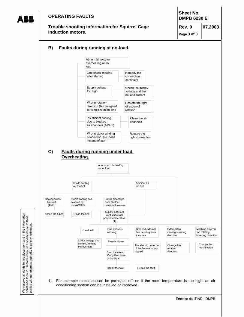
OPERATING FAULTS Trouble shooting information for Squirrel Cage Induction motors.
Emesso da ITIND - DMPB
ABB Sheet No. DMPB 6230 E
Rev. 0 Page 3 of 8
07.2003
We
rese
rve
all r
ight
s in
this
doc
umen
t and
in th
e in
form
atio
n co
ntai
ned
ther
ein.
Rep
rodu
ctio
n, u
se o
f dis
clos
ure
to th
ird
parti
es w
ithou
t exp
ress
aut
horit
y is
stri
ctly
forb
idde
n.
B) Faults during running at no-load.
C) Faults during running under load.
Overheating.
1) For example machines can be partioned off, or, if the room temperature is too high, an air
conditioning system can be installed or improved.
Abnormal noise oroverheating at noload
One phase missingafter starting
Remedy the connectioncontinuity
Supply voltagetoo high
Check the supplyvoltage and theno load current
Wrong rotationdirection (fan designedfor single rotation dir.)
Restore the rightdirection ofrotation
Insufficient coolingdue to blockedair channels (AMDT)
Clean the airchannels
Wrong stator windingconnection. (i.e. delta instead of star)
Restore theright connection
Abnormal overheating under load
Inside cooling air too hot
Cooling tubes blocked (AMD)
Clean the tubes
Frame cooling finscovered bydirt (AMDR)
Clean the fins
Hot air dischargefrom another machine too close
Supply sufficient ventilation with
proper temperature(1)
Ambient airtoo hot
Overload One phase ismissing
Stopped externalfan (feeding frominverter)
External fan rotating in wrong direction
Machine externalfan rotatingin wrong direction
Check voltage andcurrent, remedythe overload
Fuse is blown
Stop the motor.Verify the causeof the blow
Repair the fault
The electric protectionof the fan motor hastripped
Repair the fault
Change the rotationdirection
Change themachine fan

OPERATING FAULTS Trouble shooting information for Squirrel Cage Induction motors.
Emesso da ITIND - DMPB
ABB Sheet No. DMPB 6230 E
Rev. 0 Page 4 of 8
07.2003
We
rese
rve
all r
ight
s in
this
doc
umen
t and
in th
e in
form
atio
n co
ntai
ned
ther
ein.
Rep
rodu
ctio
n, u
se o
f dis
clos
ure
to th
ird
parti
es w
ithou
t exp
ress
aut
horit
y is
stri
ctly
forb
idde
n.
D) Faults during no-load or on-load running. Abnormal noise, localised overheatings, smoke etc.
E) Faults during no-load or on-load running.
High vibration levels.
Abnormal humming noise,localised overheating,smoke or sparks
Localised overheatingon the stator. Possiblesmoke or sparks
The rotor is fouling on thestator.
Strip motor for closeinspection. Consulta specialist
Overheating ofsome stator coils
Short circuitbetween turns
Strip motor for closeinspection. Consulta specialist
Periodic fluctuationof the absorbedcurrent
Rotor bars brokenor unwelded to thecage rings.
Strip the motorfor rotor inspection
The rotation speed dropssharply under load
Motor ratedpowerinsufficient
Reduce theload torque
Excessivevoltage drop
Verify characteristicsof the supply line andthe cable cross section
Abnormalnoise fromthe motor
Switch offthe motor
The noise disappear.Magnetic or electricfault
The noise gradually decreasewhith the rotational speed .Mechanic fault
Consult ABB foradvices
High vibration levels
Faulty bearings.Incorrect coupling.Damaged drive gears.
Verify the bearings,the coupling and the drive gears.
Motor unbalance(possibly also thedriven machine).
Check the balance.If necessary rebalance
Machine foundationsettled
Realign machine set.Restore correct foundation level
Machine basement toolight or in risonance with a forcing frequency.
Check the vibration level of the basement.
Change the basementdesign.
Check that the motor feet are fully supportedon the basement.
Fully support themotor feet.

OPERATING FAULTS Trouble shooting information for Squirrel Cage Induction motors.
Emesso da ITIND - DMPB
ABB Sheet No. DMPB 6230 E
Rev. 0 Page 5 of 8
07.2003
We
rese
rve
all r
ight
s in
this
doc
umen
t and
in th
e in
form
atio
n co
ntai
ned
ther
ein.
Rep
rodu
ctio
n, u
se o
f dis
clos
ure
to th
ird
parti
es w
ithou
t exp
ress
aut
horit
y is
stri
ctly
forb
idde
n.
F) Faults of the antifriction bearings (spheres or rolls).
The following table is taken from the “SKF” bearings maintenance manual,. The fault symptoms are classified in accordance to the codes : A Overheating B Noisy bearing C Too frequent replacement D High vibration level E Unsatisfactory equipment performance F Bearing loose on the shaft G Shaft is difficult to turn
SYMPTOMS A B C D E F G
Typical cause Defect Solution
x x x x Inadequate lubrication.
Grease of wrong type for the operating conditions.
Consult grease manufacturer to determine the proper type of lubricant Check miscibility if grease has been changed from one type to another.
x x x x Inadequate lubrication.
Insufficient grease in the bearing housing.
Fill housing 1/3 to 1/2 with grease.
x x Excessive lubrication.
Housing is excessively packed with grease.
Purge bearing housing until it is 1/2 filled with grease.
x x x x x Insufficient bearing clearance.
Bearing has inadequate internal clearance for the temperature caused by the heat conducted through the shaft.
Check weather the bearing had clearance according to the rating plate of the machine. If not mount a bearing according the rating plate.
x x x x x Foreign matter acting as abrasive.
Dirt, sand, carbon or other contaminants are entering the bearing housing.
Clean the bearing housing. Replace worn seals or improve the seal design to obtain adequate protection.
x x x x x Foreign matter acting as corrosive.
Water, acids, paints or other corrosives are entering the bearing housing.
Install a protective shield and/or fingers to guard against foreign matter. Improve seals.
x x x x x Foreign matter in the bearing housing.
Chips, dirt, etc. were not removed from housing before assembling the bearing unit.
Carefully clean and fill with new lubricant.
x x x x Bearing excessively preloaded.
Two locked bearings on the shaft. Insufficient axial float caused by excessive shaft expansion.
Check the “free” bearing: Improve the possibility for shaft expansion by machining the outer bearing cover.
x x x x x Outer ring spins in the housing.
Unbalanced load. Rebalance the machine or the shaft line.
x x x Noisy bearing. Flat spot on rolling elements due to skidding.
Visually check the rolling elements and replace the bearing if elements have flat spot. Make sure that the required minimum load is applied to the bearing.
x x x x x Linear and/or angular misalignment of the shaft.
Incorrect alignment of the shaft line during coupling.
Correct alignment by shimming the motor. Ensure that the shafts are coupled in a straight line. Be sure to use full support shims.
x x x x Rolling elements are dented.
Incorrect mounting method. Hammer blows on the bearing.
Replace the bearing with a new one. Never hammer any part of bearing when mounting. Always heat up the bearing for mounting.
x x x High vibrations. Excessive clearance of the bearing.
Use bearing with the prescribed internal clearance.
x x x High vibrations. Equipment is vibrating. Check the balance of the rotating parts. Rebalance the equipment. Check the stiffness of the foundation.
x Bearing is discoloured.
Distortion of the shaft and other bearing assembly components, probably due to heat.
Avoid high heat concentration at any point of the bearing to avoid distortion. Replace discoloured bearing.
x x Bearing noisy. Bearing is exposed to vibration while the motor is idle.
Carefully examine the bearing for wear spots corresponding to the spacing of rolling elements. For standby equipments, ball bearings are better suited than roller bearings to withstand idle vibrations.

OPERATING FAULTS Trouble shooting information for Squirrel Cage Induction motors.
Emesso da ITIND - DMPB
ABB Sheet No. DMPB 6230 E
Rev. 0 Page 6 of 8
07.2003
We
rese
rve
all r
ight
s in
this
doc
umen
t and
in th
e in
form
atio
n co
ntai
ned
ther
ein.
Rep
rodu
ctio
n, u
se o
f dis
clos
ure
to th
ird
parti
es w
ithou
t exp
ress
aut
horit
y is
stri
ctly
forb
idde
n.
G) Faults of the sleeve bearings.
Repair bearing journal.Replace lining.New commissioning
Change oil.Repair liningsurfaces
Repair bearinginsulation
Open bearingand adjust
Checkcoupling
Repair thecooler
Faultyinstrument?
Complete seizure of bearing
Damagedlinings
Faulty assembledbearing
Impuritiesin the oil?
Current throughthe bearing?(pittings on lining)
Has bearing beendisassembled?
Oil temperaturetoo high
High axialforces
Lubricationinsufficient
Faulty oilcooler
Faultycoupling
High bearing temperature
Follows on thenext graph

OPERATING FAULTS Trouble shooting information for Squirrel Cage Induction motors.
Emesso da ITIND - DMPB
ABB Sheet No. DMPB 6230 E
Rev. 0 Page 7 of 8
07.2003
We
rese
rve
all r
ight
s in
this
doc
umen
t and
in th
e in
form
atio
n co
ntai
ned
ther
ein.
Rep
rodu
ctio
n, u
se o
f dis
clos
ure
to th
ird
parti
es w
ithou
t exp
ress
aut
horit
y is
stri
ctly
forb
idde
n.
Impuritiesin the oil
Replacethe oil
Unstablebearingtemperature
Low oillevel
Oil ringworkingunreliable
Oil worn out
Add oil
Open bearingand adjust
Replacethe oil
Check maintenancestatus
Clean orreplace thefilter
Find fault and repair
Disassembleand adjust
Replacethe oil
Change oilquality
Verifylast adjustment
Previous bearingassembling notcorrect
Check status of oil change
Oil ring workingunreliable
Oil worn out
Verify the ABBprecriptions
Faulty oilheater
Reductionvalve shut?
Too low oil temperature
Unsuitable oil quality
Adjustflow
Motorprotectiontrips?
Oil leaks?
Oil filterclogged?
Oil pump notreliable?
Check maintenancestatus
Low oil flow
Low oillevel
Find fault and repair
Add oil
Follows from theprevious graph

OPERATING FAULTS Trouble shooting information for Squirrel Cage Induction motors.
Emesso da ITIND - DMPB
ABB Sheet No. DMPB 6230 E
Rev. 0 Page 8 of 8
07.2003
We
rese
rve
all r
ight
s in
this
doc
umen
t and
in th
e in
form
atio
n co
ntai
ned
ther
ein.
Rep
rodu
ctio
n, u
se o
f dis
clos
ure
to th
ird
parti
es w
ithou
t exp
ress
aut
horit
y is
stri
ctly
forb
idde
n.
Problems in oil flow return
Incorrectinclination ofreturn pipe?
Air locksseals outof action
Too highoil level
Damagedshaft seals
Repairand clean
Correct theoil level
Replacetha seals
Oil leaks

Asynchronous motors explosion proof Ex-d - Gas group IIB AMDR type - Size 355 - 500
Section 3
Maintenance

GENERAL CRITERIA FOR MAINTENANCE AND OVERHAUL THREE PHASE INDUCTION MOTORS EXPLOSION PROOF Ex d type
Issued by: ITIND - DMPB
ABB
Sheet No. DMPB 6185 E Rev.2 Page 1 of 2
06.2007
We
rese
rve
all r
ight
s in
this
doc
umen
t and
in th
e in
form
atio
n co
ntai
ned
ther
ein.
Rep
rodu
ctio
n, u
se o
f dis
clos
ure
to th
ird
parti
es w
ithou
t exp
ress
aut
horit
y is
stri
ctly
forb
idde
n.
Maintenance, general Conscientious and thorough maintenance of a machine and plant is the best protection against faults and operational failures. The more critical operational interruptions are for the process, then the greater should be the worth of the maintenance investments. As a basic rule for all maintenance work performed on site, the applicable safety regulations must be obeyed and the necessary protective measures taken for heavy–current installations. It is recommended that a time schedule be set up for each individual machine and that maintenance cards be employed. These maintenance cards can be kept in a card-register or computer files and possibly a copy hung into plastic envelopes at a vantage point on the machine, so that the state of maintenance can be checked at any time. Maintenance includes daily patrols by the operating personnel through the whole plant to inspect the operating conditions and to observe and note down important operating quantities. During these daily patrols, special attention is to be paid to possible deviations from the usual state of operation, especially with regard to instruments (limit values, lines or marks), liquid levels, temperatures, vibration and short-circuit monitoring. If daily patrols are not feasible due to the location of the plant (e.g. inaccessible, too remote etc.), the machines should be fitted with suitable monitoring equipment. Ideally, the periodic inspections should be carried out always by the same man. This is the best way to ensure that deviations from the normal operational behaviour are noticed. Any special observations are to be entered in the log-book. Should a fault condition arise, carefully kept log-books help to determine the cause of the fault and give information to aid remedying and eliminating the same. The actual maintenance work, most of which is performed during planned periods of shut-down, can be distinguished as follows: a) Making-up or replacing consumables b) Continuos repetitive inspections and replacing
components subject to wear, and remedying any fault or defect recognised.
c) Cleaning The maintenance schedule of this manual contains recommendations based on many years of experience. The time intervals are based on an 16 hours operating day under normal conditions. The actual circumstances under which the machines operate are often quite different so that for each particular case certain time intervals may need to be adapted to the prevailing site conditions such as dirt deposits, loading, switching frequency etc.
The recommended maintenance intervals also assume fault-free operation. After each serious fault (shut-down) an extra non-scheduled inspection of the machine or plant component in question is necessary. The cause of each shut-down is to be clarified prior to restarting. When any changes in appearance or operational behaviour are noticed it must be carefully considered whether and when intervention is necessary or whether initially a thorough inspection would be sufficient. Similarly, in the case of extraordinary operating conditions (short-circuit, overload etc.) which represent either electrical or mechanical overloading of the machine, the maintenance or inspection work is to be immediately carried out. Overhaul, general Overhauls are planned, scheduled inspections of plant equipment or of the whole plant with the object of avoiding operational failure due to damage on components or systems. When carried out at set intervals such overhauls allow supervision of wear, early recognition of any sign of damage and timely replacement of defective parts. Plant availability is not only determined by operational failures but more decisively by planned shut-down periods. The object therefore is to keep scheduled operational shut-downs to within economically acceptable limits while simultaneously attaining optimum overhaul results. This is possible on the following conditions: - Carrying out of overhaul at correct time - Accurate prediction of work to be performed - Short overhaul times by comprehensive planning
and skilful workmanship during the overhaul. Sometimes it may be practical to deviate somewhat from the maintenance schedule in order to take advantage of any occasions arising when, for reasons not necessarily related to the motors, shut-down is required. The extent of the overhaul will be largely determined by the observations made during operation.
All inspection and dismantling/reassembling work is to be performed by personnel suitably trained and qualified to operate on machines and equipments designed and manufactured to be installed in potentially explosive atmosphere. See EN 60079-17 (IEC 60079-17) and EN 60079-19 (IEC 60079-19).
Depending on the operating conditions, scheduled over – hauls every 5 years are recommended. The first over – haul should be performed after about 3000÷5000 starts or about 20000 hours of operation whichever occurs first.
GENERAL CRITERIA FOR MAINTENANCE AND OVERHAUL THREE PHASE INDUCTION MOTORS EXPLOSION PROOF Ex d type
Issued by: ITIND - DMPB
ABB
Sheet No. DMPB 6185 E Rev.2 Page 2 of 2
06.2007
We
rese
rve
all r
ight
s in
this
doc
umen
t and
in th
e in
form
atio
n co
ntai
ned
ther
ein.
Rep
rodu
ctio
n, u
se o
f dis
clos
ure
to th
ird
parti
es w
ithou
t exp
ress
aut
horit
y is
stri
ctly
forb
idde
n.
Spare parts required The probable spare parts requirements should be determined from the scope of work planned. The operator’s inventory parts should be checked for completeness and condition, in accordance with the requirements. Any additional spare parts necessary must be procured in good time. Work schedule A work schedule must be drawn up. Among other things, it shall indicate which work is to be done in the plant operator’s workshops and if the intervention of manufacturer’s personnel is required. Measurements (such as pressures, vibration, foundation dislocation, motor temperature rise, etc.) should be taken in good time before the start of the overhaul, in order to establish the actual motor parameters, which shall be compared with the design (required) values. For scheduling the complete overhaul, it is strongly recommended that a detailed work schedule be drawn up, in the form of a bar chart or, even better, a critical-path diagram. It should be noted here that by planning a quick disassembly of the machine, an early diagnosis of the problems and defects is possible, and this improves the possibility of completing unforeseen work within the allotted shut-down time. Comments to spare parts inventory A balanced spare parts inventory contributes significantly to shortening the time required for both scheduled and unscheduled outages, and hence improves the total availability of the plant. The question of which spare parts to stock and during what time, is determined chiefly by: - their probability of failure - their delivery (procurement) time - the length of time required to repair them According to these criteria, it is differentiated between emergency spare parts, which should be available at the plant even before commissioning, and parts which are recommended for long term stocking. When one or more operators in a given area have a number of identical machines in operation, then it could be advantageous to form a spare parts pool. Reconditioning work, general All bare components or parts thereof are to be cleaned (see section on cleaning) and inspected for corrosion. Any traces of rust are to be removed by brushing off, or by using a fine grinding stone etc.
Immediately afterwards spray or paint on a generous covering of rust protecting oil. If heavy rust is found on the shaft (running surfaces for seals, seats and shaft extensions), it must be removed mechanically, and the original dimensions restored by using a suitable resurfacing procedure and reworking. ABB should be consulted for such a case. In the case of intermediate storage periods, bare components or parts thereof must not come in contact with wood or damp packing material. Reconditioning of the bearings Thoroughly clean off traces of oil etc. from all bearing components (see section on cleaning).
Important! A poorly cleaned bearing surface will overheat and quickly wear out. A bearing surface is only clean when a white cloth wiped over remains white.
All raised imperfections on the surface of the babbitt metal are to be removed with a scraper. Do not use emery paper or sand paper on the white metal surface! Possible traces of rust or burrs on other metal faces of the bearing parts can be removed by using a fine grinding stone (oil stone). Repolishing will be necessary in cases where the rust has eaten in deeply. The bearing faces on the shaft journals must show no sign of burr build-up. Possibly work over with a fine grinding stone (oil stone). In the case of vertical machines with plain bearings these faces will be the top and bottom bushings and their locking nuts. Immediately afterwards coat with a rust protecting oil (ABB uses BLASOL 135 from the company Blaser, CH-3414 Haslerüegsau) or TECTYL 502 C from the company Valvoline. Because of the danger of corrosion the bearing parts must not come into contact with wood or damp packing materials during any periods of intermediate storage.

MAINTENANCE PLAN EXPLOSION PROOF THREE PHASES INDUCTION MOTORS TYPE Ex d
Issued by: ITIND-DMPB
ABB Sheet No DMPB 6146 E Rev. 3 06.2007
Page 1 of 1
We
rese
rve
all r
ight
s in
this
doc
umen
t and
in th
e in
form
atio
n co
ntai
ned
ther
ein.
Rep
rodu
ctio
n, u
se o
f di
sclo
sure
to
third
pa
rties
with
out e
xpre
ss a
utho
rity
is s
trict
ly fo
rbid
den.
Part of machine
Maintenance or inspection work
Wee
kly
Mon
thly
Qua
rter
ly
Ann
ually
Ev
ery
2 ye
ars
Ove
rhau
l
Foundation and basement
Check tightness of machine foundation bolts and state of locking elements.
Check state of alignment of the coupling and record measurements.
2)
Coupling joint
Maintenance of coupling in accordance with coupling manufacturer’s instructions
Pay attention to unusual machine noise or change in noise (e.g. rubbing or knocking sounds, etc.).
1)
Whole machine
Visually check the degree of dirt deposit inside the machine.
Bearings See relevant maintenance sheets according to the type of bearings (vibration level control is contained in these sections) Measure temperature at provided measuring points ( e.g., built-in RTD’s).
1)
Measure dielectric resistance. 1)
Stator winding
Dielectric condition diagnosis.
Visual inspection of machine inside and outside
Visual check at all accessible points for rust. 3)
Visual check for cleanness and absence of moisture from condensation
Main terminal box
Check for tightness and state of conductors, terminals and locking elements
REMARK : at reassembling of box cover smear the surfaces of the flame joint with the prescribed silicon grease Visual check for cleanness and absence of moisture from condensation
Auxiliaries terminal boxes.
Check conditions and fastening of all supply cables and connections.
REMARK : at reassembling of box cover smear the surfaces of the flame joint with the prescribed silicon grease Fan drive motor and fittings (if provided)
Visual inspection for rust and dirt Check of vibration level
3)
1) Compare with previous measurements and observations. 2) In case of vibration level increase, inspect as soon as possible and increase the check frequency. 3) Remove rust. Select method and means to suit the component involved.
REMARK : always check that the flame tightness joints dimensions remain into the prescribed tolerances and with the prescribed surface rugosity!

Monitoring the Bearing Condition by the Shock Pulse Method Rolling Bearings
Issued by: CH-UMW
ABB Sheet No. 1/7.15.14.01 E
Rev.0 Page 1 of 1
1.3.1982
We
rese
rve
all r
ight
s in
this
doc
umen
t and
in th
e in
form
atio
n co
ntai
ned
ther
ein.
Rep
rodu
ctio
n, u
se o
f dis
clos
ure
to th
ird
parti
es w
ithou
t exp
ress
aut
horit
y is
stri
ctly
forb
idde
n.
General The bearing condition can be monitored by the “Shock-Pulse Method”. All major bearing manufacturers know this “shock-pulse method” and are able to offer the instrument and give advice on request. The principle is outlined below: When a rolling element of a rolling bearing rolls over any unevenness in its path it transmits so-called shock-pulses (structure-borne noise). These shock-pulses spread throughout the material as shock waves and are measured as a criteria for monitoring the bearing condition. A piezo pick-up, set at resonance (usually at 32 kHz) is used as the sensor, its electrical signal is then processed. The original shock-pulse is converted in the indicating instrument to a “spike pulse” which can then be read off as the “SV” ( = Shock Value). In order to evaluate the measured values they must be multiplied by a scaling factor given by the speed and bore diameter of the bearing in question. The suppliers (e.g. SPM) give standard values, based on experience, which allow a bearing to be judged as being “good” (green), “fair” (yellow) or “bad” (red). Extensive measurements on new bearings by various machine manufacturers and our own experience show that: 1. Monitoring the bearing condition is only of value if
the initial SV measurement is taken and recorded during the running tests in the manufacturer’s works or at commissioning; record sheets issued by the measuring instrument manufacturer e.g. SPM should be used and later handed over to the customer.
2. The initial SV measurement could already lie in the range “fair” (yellow). However, the magnitude of the measurement alone is not decisive at it is influenced by many things such as bearing roughness, kind of lubricant, installation and load conditions.
3. After a certain running-in period, the SV measurement could decrease, i.e. the bearing condition can improve.
4. Therefore, the initial SV measurement should be taken as a reference value for further measurements.
5. The informational worth of the measurements is only given when they are taken and recorded periodically at regular intervals.
6. Measurements must always be taken for the same bearing conditions e.g. - same speed, for variable speed machines. - same load conditions, (e.g. for fans with blades
which can be adjusted during operation). - same lubrication conditions i.e. never directly
after relubrication. The new grease must be distributed within the bearing.
- same measuring points. 7. Based on the initial SV measurements, the
subsequent SV measurements indicate the trend of any change in the bearing condition. This indication of trend can be a decisive aid in planning the next machine over-haul.
Hence, it follows that the shock-pulse method is not suitable for bearing diagnosis based on a single measurement only, but periodical measurements made under the same conditions are necessary for comparison purposes, and the differences in these readings are the criterion for evaluation.
Rolling bearings maintenance and checking EXPLOSION-PROOF THREE-PHASE INDUCTION MOTORS Ex d Horizontal and vertical machines
Issued by: ITIND - DMPB
Sheet No. DMPB 6245 E Rev. 3 04.2013 Page 1 of 11
We
rese
rve
all r
ight
s in
this
doc
umen
t and
in th
e in
form
atio
n co
ntai
ned
ther
ein.
Rep
rodu
ctio
n, u
se o
f di
sclo
sure
to
third
pa
rties
with
out e
xpre
ss a
utho
rity
is s
trict
ly fo
rbid
den.
Lubrication Rolling bearings with grease lubrication (horizontal and vertical machines) Re-lubrication on the machines is foreseen in order to ensure that new grease enters into the bearing, while the old grease is eliminated By means of a regulator (grease valve) the collection of an excessive quantity of grease in the box (if present) is avoided. All the information, including the bearing identification, the quantity of grease, the re-lubrication frequency and the frequency of old grease removal (when there is a grease collection box) is indicated on the lubrication plate attached to the machine. The machine is only to be re-lubricated during rotation. When the bearings are installed in the ventilation hubs (side opposite the coupling) special grease feeding tubes and used grease collection boxes are used. The feeding tubes must always be filled with grease to the maximum level to prevent condensation forming when there is temperature fluctuation, so that no moisture enters into the bearing and corrodes the components In such cases it is better to use a grease that gives good rust protection, even in extreme environment conditions (low temperatures, temperature fluctuation, humidity).
NOTE: Where installed, the used grease collection box (under the outlet device) has to be emptied at least once a year.
Use of greases The lubrication frequency and the quantity of grease to be injected, according to the most commonly used type of bearings and the motor rotation speed, are given in the tables 7-11. In any case, check the specific motor data on the maintenance instructions plate attached to the machine for any special bearings or bearings that are not indicated in the table. The values indicated refer to normal operating conditions. If the machine is used in dirty environments, lubrication has to be more frequent. For temperatures higher than normal, the lubrication frequency in relation to operating hours (indicated on the maintenance instructions plate) has to be halved for every 15° over the normally recommended value of 70°C. The working temperature range for the recommended lubrication greases is the following: K2k or K3k lithium grease DIN 51825 Working temperature range: -20°C to +120°C. DIN 51825 standards specify the minimum physical/chemical properties for the lubrication greases. All lubricant suppliers classify their products and are able to suggest which is most appropriate. To select the re-lubrication grease, bear in mind the following:
− For re-lubrication, only greases with the same soap base as that already in the bearing are to be used- Rolling bearings are filled in the factory with a lubricating grease having a lithium soap base.
− If it is necessary to use a lubrication grease with a different soap base, first wash the bearings with industrial benzene (SANGAJOL, VARSOL, WHITESPIRIT) before filling with the new grease To carry out this operation the bearings have to be dismantled.
− For re-lubrication, when possible use only grease of the same manufacturer.
An increase in the temperature of the bearings for a short time after re-lubrication is insignificant, since it is caused by an excess of grease. During rotation the grease regulator will quickly remove the excess grease. Automatic lubricators Bearing regreasing intervals can be extended using automatic lubricators. These units can be mounted near the bearing itself and automatically provide to grease substitution. They only need to be substituted when empty, i.e. after emptying time. They are certified to be used in hazardous areas (approval II 1 GD Ex ia II C T6 T85 °C e I M 1 Ex ia I) with ambient temperatures between -20 and +60 °C (-5 +140 °F). Automatic lubricators for rolling bearings have to be mounted on the machine and activated at machine start up following these instructions:
1. Completely fill up grease feeding line to bearing (with the same grease contained in the unit or with a compatible one);
2. Mark installation date on unit envelope; 3. Remove the end cap of the lubricator; 4. Activate the lubricator rotating lubricator time
setting on the number corresponding to dispense time (see lubrication plate)
5. Clean the area around lubricating point 6. Attach the new unit hand thight 7. Is recommended to check the general
condition of the bearing and correct lubricator operation every quarter of the dispense time.
The lubricator has a delay time before starting to dispense grease to the bearing. The delay vary according to time setting and to ambient temperature: at normal ambient temperatures grease dispensing starts within a week from activation while at -20 °C (-5 °F) dispensing starts within 2 weeks. During activation period, bearing lubrication is insured by the lubricant contained in bearing housing. Also grease flow rate is influenced by ambient temperature. With temperatures below -10 °C (+14 °F) emptying time will be approximately twice than
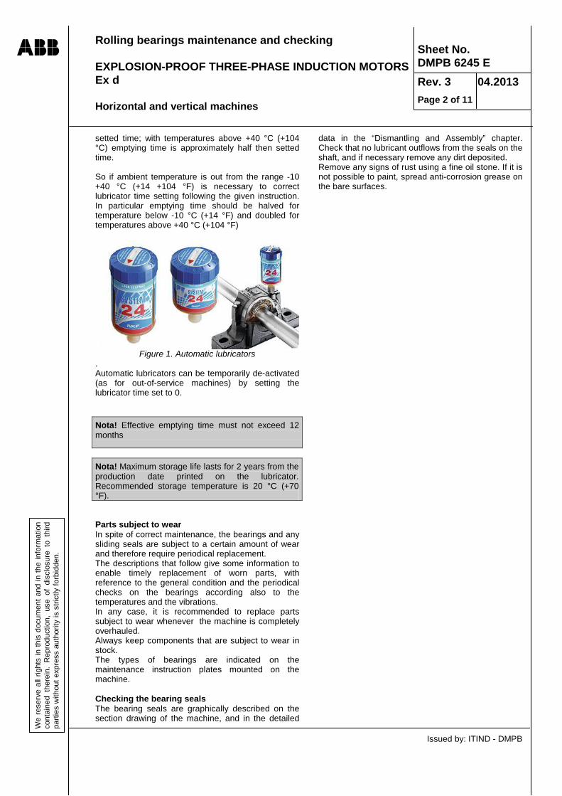
Rolling bearings maintenance and checking EXPLOSION-PROOF THREE-PHASE INDUCTION MOTORS Ex d Horizontal and vertical machines
Issued by: ITIND - DMPB
Sheet No. DMPB 6245 E Rev. 3 04.2013 Page 2 of 11
We
rese
rve
all r
ight
s in
this
doc
umen
t and
in th
e in
form
atio
n co
ntai
ned
ther
ein.
Rep
rodu
ctio
n, u
se o
f di
sclo
sure
to
third
pa
rties
with
out e
xpre
ss a
utho
rity
is s
trict
ly fo
rbid
den.
setted time; with temperatures above +40 °C (+104 °C) emptying time is approximately half then setted time. So if ambient temperature is out from the range -10 +40 °C (+14 +104 °F) is necessary to correct lubricator time setting following the given instruction. In particular emptying time should be halved for temperature below -10 °C (+14 °F) and doubled for temperatures above +40 °C (+104 °F)
Figure 1. Automatic lubricators
. Automatic lubricators can be temporarily de-activated (as for out-of-service machines) by setting the lubricator time set to 0.
Nota! Effective emptying time must not exceed 12 months
Nota! Maximum storage life lasts for 2 years from the production date printed on the lubricator. Recommended storage temperature is 20 °C (+70 °F). Parts subject to wear In spite of correct maintenance, the bearings and any sliding seals are subject to a certain amount of wear and therefore require periodical replacement. The descriptions that follow give some information to enable timely replacement of worn parts, with reference to the general condition and the periodical checks on the bearings according also to the temperatures and the vibrations. In any case, it is recommended to replace parts subject to wear whenever the machine is completely overhauled. Always keep components that are subject to wear in stock. The types of bearings are indicated on the maintenance instruction plates mounted on the machine. Checking the bearing seals The bearing seals are graphically described on the section drawing of the machine, and in the detailed
data in the “Dismantling and Assembly” chapter. Check that no lubricant outflows from the seals on the shaft, and if necessary remove any dirt deposited. Remove any signs of rust using a fine oil stone. If it is not possible to paint, spread anti-corrosion grease on the bare surfaces.

Rolling bearings maintenance and checking EXPLOSION-PROOF THREE-PHASE INDUCTION MOTORS Ex d Horizontal and vertical machines
Issued by: ITIND - DMPB
Sheet No. DMPB 6245 E Rev. 3 04.2013 Page 3 of 11
We
rese
rve
all r
ight
s in
this
doc
umen
t and
in th
e in
form
atio
n co
ntai
ned
ther
ein.
Rep
rodu
ctio
n, u
se o
f di
sclo
sure
to
third
pa
rties
with
out e
xpre
ss a
utho
rity
is s
trict
ly fo
rbid
den.
Monitoring and control of rolling bearings on horizontal and vertical machines Temperature monitoring Various instruments can be fitted to monitor the bearing temperature. However, if no instrument is fitted. The temperature can be measured using portable instruments. If an anomalous temperature is found, that is higher than normal, check with a precision thermometer. The temperature detector supplied with the machine, or fitted at a later date is to measure the temperatures of the bearing outer ring. To set the protection controlled by the temperature detector (or according to decisions made based on the manual temperature measurement) on horizontal and vertical machines with rolling bearings lubricated with oil or grease, see the relevant document. In any case an over temperature limit of 50°C is recommended, in relation to the actual environment temperature value. The temperature is to be measured periodically. An increase in the bearings temperature could indicate the start or the development of damage caused by lack of lubricant, metal detachment or component wear, entry of foreign matter, cage breakage or other similar causes. The operating conditions of a bearing cannot be assessed just by the temperature level, but above all according to its behavior over time. If thermometers are installed, the trend of the temperature can be monitored making notes and recording the various values. If the temperature of the bearings increases in relation to values of previous readings, try to find the cause with the machine stationary. Operating quality monitoring (measurement of bearing housings vibration) Set any vibration sensors supplied according to the values given below, or use these values to assess the vibration measurements made with portable instruments. The vibration limit values that trigger an alarm have been defined on the basis of the indications contained in ISO Standard 10816. This instruction is basically valid also for NEMA, API and other similar standards.
The values are valid for: • Vibrations originating from the machine itself. • Machines on rigid foundations. Rigid foundations
definition in conformity with ISO standard 10816: “For a rigid foundation the system natural frequency is higher than the rotation speed frequency”.
The values are not applicable (usually) for: • Alternative compressor drives. • Machines on foundations with low system natural
vibration frequency (machines + foundations), i.e. ≤ 0.25 x rotation speed frequency
For these machines, it is opportune that the values are agreed between the manufacturer and the customer at the time of ordering. Vibrations detected on the bearing housings The decisive quantity is the actual vibration velocity measured on the bearing housing The position of the measuring point is defined on the basis of ISO Standard 10816. The recommended values to set the protection devices activation controlled by the detectors (or according to decisions made based on manual measurement) are the following: ALARM Vrms= 4.5 mm/s BLOCK Vrms = 7.1 mm/s
NOTE: The above values are, in fact, lower than the limits recommended by ISO Standard 10816. The restriction of the allowed levels is due to the particular design solutions of the Ex d motors flame arresters, that have a very small gap between the motor fixed part and the rotating shaft.
Converting of vibration velocity Vms to vibration amplitude S In order to have a comparison with the measured values, the vibration amplitude S can be calculated as follows (supposing that vibration is sinusoidal):
f= rotation frequency in revs per second Vrms = vibration speed (mm/sec) S= vibration amplitude from 0 to peak (mm) A conversion nomograph is given below.
fV
xf
Vx
xxV
S rmsrmsrms 225,0~2
22πω
==

Rolling bearings maintenance and checking EXPLOSION-PROOF THREE-PHASE INDUCTION MOTORS Ex d Horizontal and vertical machines
Issued by: ITIND - DMPB
Sheet No. DMPB 6245 E Rev. 3 04.2013 Page 4 of 11
We
rese
rve
all r
ight
s in
this
doc
umen
t and
in th
e in
form
atio
n co
ntai
ned
ther
ein.
Rep
rodu
ctio
n, u
se o
f di
sclo
sure
to
third
pa
rties
with
out e
xpre
ss a
utho
rity
is s
trict
ly fo
rbid
den.
Design solutions The standard design solution for horizontal machines use ball bearings on both sides. With these exceptions: • 2-pole motors of the welded frame AMDR series that have a cylindrical roller bearing on the NDE side. • AMDT motors, size 710 - 900 that have cylindrical roller bearings on both sides, plus an additional axial locking bearing
on the DE side. Vertical machines have ball bearings (similar to those used on the horizontal machines) on the DE side (low side), whereas on the NDE side ball bearings or angular contact ball bearings can be used according to the weight and velocity of the rotor. For vertical 4 and more poles cast iron frame AMDR machines and for vertical 2 poles welded frame AMDR machines the rotor weight is withstood by DE ball bearing. Check on the specific technical documentation for any non-standard solutions or for working conditions that could require different lubrication intervals.

Rolling bearings maintenance and checking EXPLOSION-PROOF THREE-PHASE INDUCTION MOTORS Ex d Horizontal and vertical machines
Issued by: ITIND - DMPB
Sheet No. DMPB 6245 E Rev. 3 04.2013 Page 5 of 11
We
rese
rve
all r
ight
s in
this
doc
umen
t and
in th
e in
form
atio
n co
ntai
ned
ther
ein.
Rep
rodu
ctio
n, u
se o
f di
sclo
sure
to
third
pa
rties
with
out e
xpre
ss a
utho
rity
is s
trict
ly fo
rbid
den.
Table 1. Standard Bearings for motors with rib cooling circuit, IIB/IIC, cast iron frame AMD horizontal assembly.
Size N° of Poles D end N end
355...R…gM 2 6316 6316 355...R…gM 4 - 6 6322 6316 400...R…gM 2 6317 6317 400...R…gM 4 - 6 6324 6319
Table 2. Standard Bearings for motors with rib cooling circuit, IIB/IIC, welded frame AMD horizontal assembly.
Size N° of Poles D end N end
450 .. R…M 2 6317 NU215 450 .. R…M 4 - 10 6324 6321 500 .. R…M 2 6319 NU217 500 .. R…M 4 - 12 6326 6324
Table 3. Standard Bearings for AMD motors with tube cooling circuit and horizontal assembly.
Size N° of Poles Side Frequency
50 Hz 60 Hz
500…T 2 D 6317 – C3 (a) N 6317 – C3 (a)
500…T ≥ 4 D 6324 – C3 N 6319 – C3
560…T 2 D 6319 – C3 (a) N 6319 – C3 (a)
560…T ≥ 4 D 6326 – C3 N 6322 – C3
630…T 2 D (b) (b) N (b) (b)
630…T ≥ 4 D 6330 – C3 N 6324 – C3
710…T 2 D (b) (b) N (b) (b)
710…T ≥ 4 D
6034 – C3 NU1034 EC
N NU322 EC3
900…T
4 D 6044 – M1C3 NU1044 – M1C3
N NU1044 – M1C3
≥ 6 D 6048 – M1C3 NU1048 – M1C3
N NU1048 – M1C3 (a) : Not standard; (b): not available; (c): with limited life (≈ 40000 H)

Rolling bearings maintenance and checking EXPLOSION-PROOF THREE-PHASE INDUCTION MOTORS Ex d Horizontal and vertical machines
Issued by: ITIND - DMPB
Sheet No. DMPB 6245 E Rev. 3 04.2013 Page 6 of 11
We
rese
rve
all r
ight
s in
this
doc
umen
t and
in th
e in
form
atio
n co
ntai
ned
ther
ein.
Rep
rodu
ctio
n, u
se o
f di
sclo
sure
to
third
pa
rties
with
out e
xpre
ss a
utho
rity
is s
trict
ly fo
rbid
den.
Table 4. Standard Bearings for motors with rib cooling circuit, IIB/IIC, cast iron frame AMD vertical assembly. Size N° of Poles D end N end
355...R..gM 2 6316 7213 355...R..gM 4 - 6 6322 6316 400...R..gM 2 6217 7217 400...R..gM 4 - 6 6324 6319
Table 5. Standard Bearings for motors with rib cooling circuit, IIB/IIC, welded frame AMD horizontal assembly.
Size N° of Poles D end N end
450...R…M 2 NU 215 6317 450...R…M 4 - 12 6324 7321 500...R…M 4 - 12 6326 7321
Table 6. Standard Bearings for AMD motors with tube cooling circuit and vertical assembly.
Size N° of Poles Side Frequency
50 Hz 60 Hz
500…T ≥ 4 D 6024 - C3 6024 - C3 500…T ≥ 4 N 7319 7319 560…T ≥ 4 D 6026 - C3 6026 - C3 560…T ≥ 4 N 7322 7322 630…T ≥ 4 D 6030 - C3 6030 - C3 630…T ≥ 4 N 7324 7324 710…T 4 D (a) (b) 710…T 4 N (a) (b) 710…T ≥ 6 D 6034 - C3 6034 - C3 710…T ≥ 6 N 7330 7330 900…T ≥ 6 D 6044 – C3 6044 – C3 900…T ≥ 6 N 2x 7334 2x 7334
(a) : Not standard; (b): not available; (c): with limited life (<40000 H) Table 7. Lubrication frequency, in hours, for operation at 50 Hz and horizontal assembly, for AMD motors with rib cooling circuit, IIB/IIC, welded frame.
Size N° of Poles Grease (g)
2 4 6 8 10 12 2 poles 4-n poles
450…R…M 2000 6000 8800 8800 8800 8800 45 70 500…R…M 1500 5000 8800 8800 8800 8800 45 80

Rolling bearings maintenance and checking EXPLOSION-PROOF THREE-PHASE INDUCTION MOTORS Ex d Horizontal and vertical machines
Issued by: ITIND - DMPB
Sheet No. DMPB 6245 E Rev. 3 04.2013 Page 7 of 11
We
rese
rve
all r
ight
s in
this
doc
umen
t and
in th
e in
form
atio
n co
ntai
ned
ther
ein.
Rep
rodu
ctio
n, u
se o
f di
sclo
sure
to
third
pa
rties
with
out e
xpre
ss a
utho
rity
is s
trict
ly fo
rbid
den.
Table 8. Lubrication frequency, in hours, for operation at 60 Hz and horizontal assembly, for AMD motors with rib cooling circuit, IIB/IIC, welded frame.
Size N° of Poles Grease (g)
2 4 6 8 10 12 2 poles 4-n poles
450…R…M 1300 4300 8800 8800 8800 8800 45 70 500…R…M / 3500 8800 8800 8800 8800 / 80
Table 9. Lubrication frequency, in hours, for operation at 50 Hz and horizontal assembly, for AMD motors with tubes cooling circuit, IIB/IIC, welded frame.
Size N° of Poles Grease (g)
2 4 6 8 10 12 2 poles 4-n poles
500..T 3000 6000 / / / / 35 70 560..T 2500 5000 8800 8800 8800 8800 45 80 630..T / 4000 8000 8800 8800 8800 / 90 710..T / 1900 4000 6000 7000 8800 / 55 x 2 900..T / 600 750 1550 1850 2350 / 100
14 16 18 6-n poles
900..T 2850 3250 3450 100 Table 9 A. Lubrication frequency, in hours, for operation at 60 Hz and horizontal assembly, for AMD motors with tubes cooling circuit, IIB/IIC, welded frame.
Size N° of Poles Grease (g)
2 4 6 8 10 12 2 poles 4-n poles
500..T 2000 4000 / / / / 35 70 560..T / 3500 7000 8800 8800 8800 45 80 630..T / 2500 6000 8800 8800 8800 / 90 710..T / 1000 2500 4500 5000 6000 / 55 x 2 900..T / 300 450 1000 1400 1800 / 100
14 16 18 6-n poles
900..T 2300 2500 3000 100
Table 10. Lubrication frequency, in hours, for operation at 50 Hz and horizontal assembly, for AMD motors with rib cooling circuit, IIB/IIC, cast iron frame.
Size N° of Poles Grease (g)
2 4 6 8 10 12 2 poles 4-n poles
355...R…gM 3100 8100 8800 / / / 35 60 400...R…gM 2500 7000 8800 8800 / / 45 60
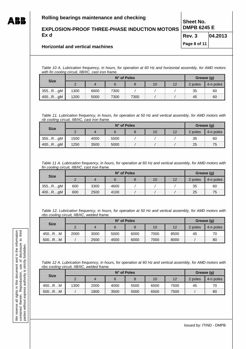
Rolling bearings maintenance and checking EXPLOSION-PROOF THREE-PHASE INDUCTION MOTORS Ex d Horizontal and vertical machines
Issued by: ITIND - DMPB
Sheet No. DMPB 6245 E Rev. 3 04.2013 Page 8 of 11
We
rese
rve
all r
ight
s in
this
doc
umen
t and
in th
e in
form
atio
n co
ntai
ned
ther
ein.
Rep
rodu
ctio
n, u
se o
f di
sclo
sure
to
third
pa
rties
with
out e
xpre
ss a
utho
rity
is s
trict
ly fo
rbid
den.
Table 10 A. Lubrication frequency, in hours, for operation at 60 Hz and horizontal assembly, for AMD motors with fin cooling circuit, IIB/IIC, cast iron frame.
Size N° of Poles Grease (g)
2 4 6 8 10 12 2 poles 4-n poles
355...R…gM 1300 6600 7300 / / / 35 60 400...R…gM 1200 5000 7300 7300 / / 45 60 Table 11. Lubrication frequency, in hours, for operation at 50 Hz and vertical assembly, for AMD motors with rib cooling circuit, IIB/IIC, cast iron frame.
Size N° of Poles Grease (g)
2 4 6 8 10 12 2 poles 4-n poles
355...R…gM 1500 4000 5500 / / / 35 60 400...R…gM 1250 3500 5000 / / / 25 75 Table 11 A. Lubrication frequency, in hours, for operation at 60 Hz and vertical assembly, for AMD motors with fin cooling circuit, IIB/IIC, cast iron frame.
Size N° of Poles Grease (g)
2 4 6 8 10 12 2 poles 4-n poles
355...R…gM 600 3300 4600 / / / 35 60 400...R…gM 600 2500 4100 / / / 25 75 Table 12. Lubrication frequency, in hours, for operation at 50 Hz and vertical assembly, for AMD motors with ribs cooling circuit, IIB/IIC, welded frame.
Size N° of Poles Grease (g)
2 4 6 8 10 12 2 poles 4-n poles
450...R…M 2000 3000 5000 6000 7000 8500 45 70 500...R…M / 2500 4500 6000 7000 8000 / 80
Table 12 A. Lubrication frequency, in hours, for operation at 60 Hz and vertical assembly, for AMD motors with ribs cooling circuit, IIB/IIC, welded frame.
Size N° of Poles Grease (g)
2 4 6 8 10 12 2 poles 4-n poles
450...R…M 1300 2000 4000 5500 6500 7500 45 70 500...R…M / 1800 3500 5000 6500 7500 / 80

Rolling bearings maintenance and checking EXPLOSION-PROOF THREE-PHASE INDUCTION MOTORS Ex d Horizontal and vertical machines
Issued by: ITIND - DMPB
Sheet No. DMPB 6245 E Rev. 3 04.2013 Page 9 of 11
We
rese
rve
all r
ight
s in
this
doc
umen
t and
in th
e in
form
atio
n co
ntai
ned
ther
ein.
Rep
rodu
ctio
n, u
se o
f di
sclo
sure
to
third
pa
rties
with
out e
xpre
ss a
utho
rity
is s
trict
ly fo
rbid
den.
Table 13. Lubrication frequency, in hours, for operation at 50 Hz and vertical assembly, for AMD motors with tubes cooling circuit, IIB/IIC, welded frame.
Size N° of Poles Grease (g)
2 4 6 8 10 12 2 poles 4-n poles
500..T / 4000 6000 7500 8500 8800 / 70 560..T / 3500 5500 7000 8000 8800 / 80 630..T / 3000 5000 6500 7500 8500 / 90 710..T / 2000 4000 5500 7000 8000 / 55 x 2 900..T / / 2400 3600 4600 5400 / /
14 16 18 6-n poles
900..T 6000 6500 6800 2x130 Table 13 A. Lubrication frequency, in hours, for operation at 60 Hz and vertical assembly, for AMD motors with tubes cooling circuit, IIB/IIC, welded frame.
Size N° of Poles Grease (g)
2 4 6 8 10 12 2 poles 4-n poles
500..T / 3000 5000 6500 7500 8500 / 70 560..T / 2500 4500 6000 7000 8000 / 80 630..T / 2000 4000 5500 6500 7500 / 90 710..T / 1500 3000 4500 6000 7000 / 55 x 2 900..T / / 1800 2800 3800 4600 / /
14 16 18 6-n poles
900..T 5300 5800 6200 2x130 The calculation has been made considering an environment temperature of 40°C; if the estimated temperature is different. The values given are to be changed as a consequence; the lubrication frequency is to be halved every 15K over the reference value. The lubrication intervals are not to be longer than once a year. Because of the short distance between the fixed and rotating parts of the flame extinguisher, for explosion-proof motors the maximum load that can be supported by the bearing is lower than for normal motors; this is why the lubrication intervals are not reduced.
NOTE! The lubrication intervals indicated in the table are only indicative. For the correct values of the specific application, always refer to the values indicated on the plate on board the machine.
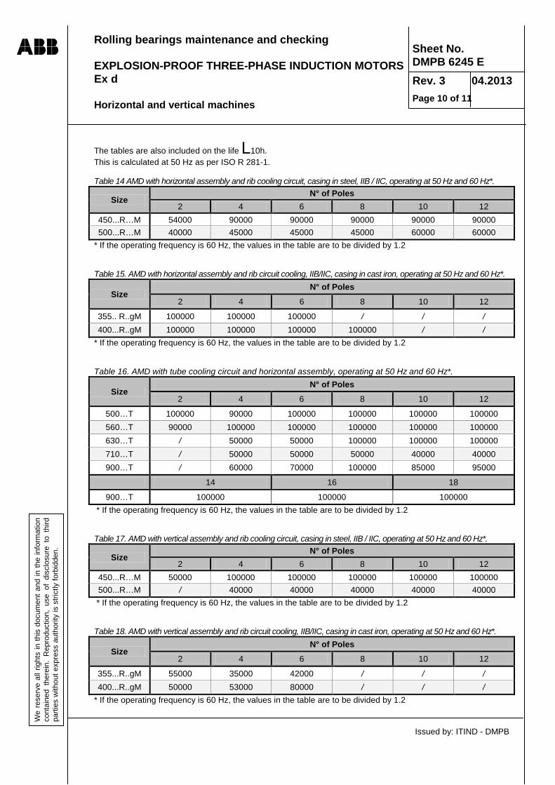
Rolling bearings maintenance and checking EXPLOSION-PROOF THREE-PHASE INDUCTION MOTORS Ex d Horizontal and vertical machines
Issued by: ITIND - DMPB
Sheet No. DMPB 6245 E Rev. 3 04.2013 Page 10 of 11
We
rese
rve
all r
ight
s in
this
doc
umen
t and
in th
e in
form
atio
n co
ntai
ned
ther
ein.
Rep
rodu
ctio
n, u
se o
f di
sclo
sure
to
third
pa
rties
with
out e
xpre
ss a
utho
rity
is s
trict
ly fo
rbid
den.
The tables are also included on the life L10h. This is calculated at 50 Hz as per ISO R 281-1. Table 14 AMD with horizontal assembly and rib cooling circuit, casing in steel, IIB / IIC, operating at 50 Hz and 60 Hz*.
Size N° of Poles
2 4 6 8 10 12 450...R…M 54000 90000 90000 90000 90000 90000 500...R…M 40000 45000 45000 45000 60000 60000
* If the operating frequency is 60 Hz, the values in the table are to be divided by 1.2 Table 15. AMD with horizontal assembly and rib circuit cooling, IIB/IIC, casing in cast iron, operating at 50 Hz and 60 Hz*.
Size N° of Poles
2 4 6 8 10 12
355.. R..gM 100000 100000 100000 / / / 400...R..gM 100000 100000 100000 100000 / /
* If the operating frequency is 60 Hz, the values in the table are to be divided by 1.2 Table 16. AMD with tube cooling circuit and horizontal assembly, operating at 50 Hz and 60 Hz*.
Size N° of Poles
2 4 6 8 10 12
500…T 100000 90000 100000 100000 100000 100000 560…T 90000 100000 100000 100000 100000 100000 630…T / 50000 50000 100000 100000 100000 710…T / 50000 50000 50000 40000 40000 900…T / 60000 70000 100000 85000 95000
14 16 18
900…T 100000 100000 100000 * If the operating frequency is 60 Hz, the values in the table are to be divided by 1.2 Table 17. AMD with vertical assembly and rib cooling circuit, casing in steel, IIB / IIC, operating at 50 Hz and 60 Hz*.
Size N° of Poles
2 4 6 8 10 12 450...R…M 50000 100000 100000 100000 100000 100000 500...R…M / 40000 40000 40000 40000 40000
* If the operating frequency is 60 Hz, the values in the table are to be divided by 1.2 Table 18. AMD with vertical assembly and rib circuit cooling, IIB/IIC, casing in cast iron, operating at 50 Hz and 60 Hz*.
Size N° of Poles
2 4 6 8 10 12
355...R..gM 55000 35000 42000 / / / 400...R..gM 50000 53000 80000 / / /
* If the operating frequency is 60 Hz, the values in the table are to be divided by 1.2
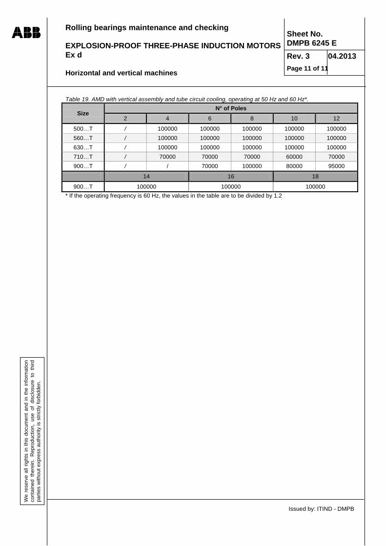
Rolling bearings maintenance and checking EXPLOSION-PROOF THREE-PHASE INDUCTION MOTORS Ex d Horizontal and vertical machines
Issued by: ITIND - DMPB
Sheet No. DMPB 6245 E Rev. 3 04.2013 Page 11 of 11
We
rese
rve
all r
ight
s in
this
doc
umen
t and
in th
e in
form
atio
n co
ntai
ned
ther
ein.
Rep
rodu
ctio
n, u
se o
f di
sclo
sure
to
third
pa
rties
with
out e
xpre
ss a
utho
rity
is s
trict
ly fo
rbid
den.
Table 19. AMD with vertical assembly and tube circuit cooling, operating at 50 Hz and 60 Hz*.
Size N° of Poles
2 4 6 8 10 12
500…T / 100000 100000 100000 100000 100000 560…T / 100000 100000 100000 100000 100000 630…T / 100000 100000 100000 100000 100000 710…T / 70000 70000 70000 60000 70000 900…T / / 70000 100000 80000 95000
14 16 18
900…T 100000 100000 100000 * If the operating frequency is 60 Hz, the values in the table are to be divided by 1.2

RECOMMENDED LUBRICATING GREASE
Issued by: ITIND-DMPB
Sheet No DMPB 6180 E Rev. 4 Page 1 of 2
01.2013
We
rese
rve
all r
ight
s in
this
doc
umen
t and
in th
e in
form
atio
n co
ntai
ned
ther
ein.
Rep
rodu
ctio
n, u
se o
f dis
clos
ure
to th
ird
parti
es w
ithou
t exp
ress
aut
horit
y is
stri
ctly
forb
idde
n.
ATTENTION: • The grease to be used is always indicated on the bearing plates fixed on the machine. Here are reported some general rules • For 2 poles motors special additivated greases should be used like : ESSO UNIREX N, or equivalent. • In case of very low ambient temperature, below -30° C synthetic base oil greases should be used like:
MOBILGREASE28 or equivalent. • For vertical motors lithium soap greases NLGI grade 3 are preferably used. Various brands of recommended lubricating greases. The following list should be considered as being a random selected from brands available on the market with no preference given to any particular brand. These greases have all lithium (or lithium/calcium) thickener soap and mineral base oil
Recommended standard lubricants.
Manufacturer Quality Thickener Base oil Tempera-ture range
[°C]
Kinematic viscosity of
base oil [mm2/s, cSt
at 40°C]
Kinematic viscosity of
base oil [mm2/s, cSt at 100°C]
Consis-tency [NLGI scale]
ESSO UNIREX N2 Li Mineral -30 to +165 115 12.2 2
ESSO UNIREX N3 Li Mineral -30 to +165 115 12.2 3
ESSO BEACON 2 Li Mineral -40 to +120 100 9.5 2
SKF LGMT 2 Li Mineral -30 to +120 92 9.6 2
MOBIL OIL Mobilux 2 Li Mineral -30 to +120 100 10.0 2
SHELL Alvania Grease G2 Li/Ca Mineral -25 to +140 100 11 2
SHELL Alvania Grease G3 Li/Ca Mineral -20 to +150 100 11 2
TEBOIL Multi-Purpose Grease
Li Mineral -30 to +110 110 10.5 2
BP Energrease LS 2 Li Mineral -30 to +110 92 9.5 2
STATOIL Uniway Li 42 Li Mineral -30 to +120 100 12.0 2

RECOMMENDED LUBRICATING GREASE
Issued by: ITIND-DMPB
Sheet No DMPB 6180 E Rev. 4 Page 2 of 2
01.2013
We
rese
rve
all r
ight
s in
this
doc
umen
t and
in th
e in
form
atio
n co
ntai
ned
ther
ein.
Rep
rodu
ctio
n, u
se o
f dis
clos
ure
to th
ird
parti
es w
ithou
t exp
ress
aut
horit
y is
stri
ctly
forb
idde
n.
Recommended high temperature greases.
Manufacturer Quality Thickener Base oil Tempera-ture range
[°C]
Kinematic viscosity of
base oil [mm2/s, cSt
at 40°C]
Kinematic viscosity of
base oil [mm2/s, cSt at 100°C]
Consis-tency [NLGI scale]
ESSO UNIREX N3 Li-comp. Mineral -30 to +165 115 12.2 3
SKF LGHT 3 Li-comp. Mineral -30 to +150 110 13.0 3
MOBIL OIL Mobiltemp SHC 100 Inorga. Synthetic -40 to +200 100 12.5 2
SHELL Syntix 100 Li-comp. Synthetic -40 to +150 100 21.0 2
TEBOIL Syntex Grease Li-comp. Synthetic -40 to +140 150 20.0 2
STATOIL Uniway LiX 42 PA Li-comp. Polyalfa -35 to +150 100 18.0 2
CHEVRON SRI 2 Polyr. Mineral -30 to +150 115 14.0 2
NESTE Rasva 606 Li-comp. Synthetic -40 to +150 150 20.0 2
MOBIL OIL Mobilgrease 28 Clay Synthetic -54 to +177 30 5.7 2
SHELL AeroShell Grease 22 Microgel Synthetic -65 to +204 30.5 5.8 2
SKF LGLT 2 Lithium Synthetic -50 to +110 18 4.5 2
1) NLGI Grade = Grease Consistency Classification according to “NATIONAL LUBRICATING GREASE INSTITUTE” (USA) NLGI Grade 2 is normally used for 4-6 poles horizontal machines NLGI Grade 3 is normally used for 8 and more poles horizontal machines and for vertical machines
REMARK : motors are lubricated in the factory with the following greases 2 pole horizontal motors : ESSO UNIREX N3 ≥ 4 poles horizontal motors : MOBILUX EP2 vertical machines : ESSO UNIREX N3 motor for ambient temperature below –20°C: MOBILGREASE 28 – AEROSHELL GREASE 22 WARNING: some greases are not miscible with others. In case of doubt, ask for compatibility to grease manufacturer. For lubrication instructions please refer to maintenance for rolling bearings: - Sheet N° DMPB 6245 for AMD machines; - Sheet N° 1/7.15.12.04 for AMB - AMC – AMI - AML - AMLi machines.

Maintenance Plan Rolling Bearings for Horizontal and Vertical Machines
ABB Sheet No. 1/7.15.12.06 E
Rev.0 Page 1 of 1
1.1.1993
e re
serv
e al
l rig
hts
in th
is d
ocum
ent a
nd in
the
info
rmat
ion
use
of d
iscl
osur
e to
third
ith
out e
xpre
ss a
utho
rity
is s
trict
ly fo
rbid
den.
Part of machine Sheet No. Maintenance or inspection work
Wee
kly
Mon
thly
Ever
y 3
m.
Annu
ally
Ever
y 2
y.
At o
verh
aul
Measure and record temperature at measuring points provided, by hand checks or by thermometer if fitted.
1)2)
2)
Measure machine vibration using either the vibration sensor provided or a portable instrument on: horizontal machines: on bearing housing, horizontal/vertical. Vertical machines: on end-shield, horizontal in two directions.
2)
Measure and record condition of bearings using the shock-pulse-method (e.g. SPM) and using record sheets from e.g. SPM.
3)
Rolling bearings Relubricate the bearings, only when the machine Is running. 1)4)
Check bearing seals for oil leakage and clean if dirty.
2)
Replace worn parts (bearings, sliding or rubbing seals etc.)
**)
Wash out bearings (rolling bearings) and repack with grease.
1)
Check for rust.
5) 1) Applicable for grease lubricated rolling bearings.
2) Compare with earlier measurements and observations.
3) Always take measurements at same speed and operating conditions.
4) Consult relubrication intervals on maintenance instruction plates on the machine, or refer to Outline drawing. If bearing temperatures exceed 70°C and/or with dusty environment the relubrication and used grease removal intervals must be shortened. Machines which are often stationary must be relubricated after 1 year at the latest. This is necessary because of grease ageing, possible condensation in the bearing housings etc.
5) Remove possible rust by using a fine oil stone. Where painting is not possible, coat bare surfaces with an anti-corrosion
covering. **) At each complete overhaul or immediately when this appears necessary because of temperature, vibration or bearing
condition measurements. Experience has shown that failure of rolling bearings is not so much caused by material fatigue as by wear. Wear is dependent upon the operating conditions.
Issued by: CH-UMW
W cont
aine
d th
erei
n. R
epro
duct
ion,
pa
rties
w

SLEEVE BEARINGS MAINTENANCE Explosion proof three phase Induction motors Ex d Horizontal machines
Issued by: ITIND -DMPB
ABB Sheet No. DMPB 6186 E
Rev. 3 Page 1 of 4
06.2007
We
rese
rve
all r
ight
s in
this
doc
umen
t and
in th
e in
form
atio
n co
ntai
ned
ther
ein.
Rep
rodu
ctio
n, u
se o
f dis
clos
ure
to th
ird
parti
es w
ithou
t exp
ress
aut
horit
y is
stri
ctly
forb
idde
n.
Sleeve bearings Ex d motors are always designed with endshield bearings. The kind of bearing and details thereof are described in the specific technical documentation of the Order. The bearings with self-lubrication are supplied with oil from the oil sump by one or more oil rings. The oil rings can be either single piece or split design. One opening is provided in the bearing housings through which the oil rings can be checked for correct functioning (e.g. uniform and smooth running, oil transport). Lateral openings are even provided, fitted with sight windows. General points concerning sleeve bearings The bearing housings of horizontal machines and those of vertical machines are all fitted with at least one oil sight window. When the bearing is fitted inside a ventilation hub the sight window is placed outside the hub. The maintenance instruction plate fastened to the machine shows data such as initial oil fill quantity per bearing, rate of oil flow per bearing, oil type and oil change interval. The lube oil may only be topped up or changed when the machine is stationary. When filling with oil observe the level at the bearing oil sight window on the bearing housing. The correct level is indicated by a mark in the middle of the sight window. The level must not fall below the lower rim of the sight window. These oil level details are referred to the stationary machine and to an oil temperature equal to the ambient temperature. During operation, the oil level in the bearings will rise somewhat. This is absolutely normal and does not represent a danger of oil overflowing into the machine. After shutting the machine down and awaiting the oil to be cooled, check that the level falls to the mark on the sight window; if not, refill. Whenever the bearing shells or the bearing segments are changed, run the machine for approximately 3 hours with the new parts and then drain the oil from the bearing housings. Flush out bearings with non-halogens industrial solvents (SANGAJOL, VARSOL, or WHITE SPIRIT) and refill with new oil. This measure ensures that any metal particles rubbed off during running-in are removed from the bearing housings. In the case of sleeve bearings, a bearing inspection after running on load for some hours during commissioning or changing the shells is the best precaution to avoid possible damages and improve the motor availability. Bearing insulation The arrangement of the bearing insulation (if any), is shown on the separate sheet “Bearing insulation” and on the technical documentation of the Order. These documents also indicates whether one or both bearings are insulated, and whether the insulation on one bearing is bridged over for measuring purposes.
Oil change Oil changing is largely dependent upon the operating time, the number of switching operations, the operating temperatures and the amount of oil contamination. If not otherwise specified on the rating plate, cleaning periods are advisable during operations with an oil change after approximately 8000 operating hours in case of self-lubricating bearings and approximately 20000 operating hours in case of circulating oil lubricated bearings. Shorter intervals are required in case of frequent starting and stopping, high oil temperatures or excessive contamination through external influences, for example. An oil change can also be required by strong turbidity or by a sudden increase in temperature without any external influence. A chemical analysis offers reliable information on the lubricity (ageing) of the oil. The first examination is to be made during commissioning, with further examinations after 6 or 18 months. On the basis of these examinations the extension the oil change interval can be decided, mainly when large quantity of oil is involved. Types of oil The oil used in the bearings must have a viscosity value as defined in ISO 3448. As a general rule, the following mineral oils are used in the motors.
Rotational speed of the shaft journals (rpm)
Oil types
> 1800 • ISO VG 32 • 150 SSU/100°F
between 1200 and 1800 • ISO VG 46 • 214 SSU/100°F
≤ 1200 • ISO VG 68 • 315 SSU/100°F
REMARK: For use of synthetic oils, ask information from the machine manufacturer!
Here are indicated some type of oil easily obtained on the market and suitable for the use on electric motors
2 and 4 poles motors
Supplier ISO VG 32 150 SSU/100°F
ISO VG 46 214 SSU/100°F
EXXON Teresso 32 Teresso 46 SHELL Tellus Oil S32 Tellus Oil S46 MOBIL DTE24 DTE25
BP Energol CS32 Energol CS46 TEXACO Rando Oil 32 Rando Oil 46
FINA CIRKAN 32 CIRKAN 46

SLEEVE BEARINGS MAINTENANCE Explosion proof three phase Induction motors Ex d Horizontal machines
Issued by: ITIND -DMPB
ABB Sheet No. DMPB 6186 E
Rev. 3 Page 2 of 4
06.2007
We
rese
rve
all r
ight
s in
this
doc
umen
t and
in th
e in
form
atio
n co
ntai
ned
ther
ein.
Rep
rodu
ctio
n, u
se o
f dis
clos
ure
to th
ird
parti
es w
ithou
t exp
ress
aut
horit
y is
stri
ctly
forb
idde
n.
6 and more poles motors
Supplier ISO VG 68 315 SSU/100°F
EXXON Teresso 68 SHELL Tellus Oil S68 MOBIL DTE26
BP Energol CS68 TEXACO Rando Oil 68
FINA CIRKAN 68
REMARK: The required value of ISO VG viscosity for the oil is clearly indicated on the outline drawing of the motor and on the lubrication plates.
Parts subjected to wear When the machine starts up and runs down, it passes through the mixed friction zone, i.e. the shaft speed is too low, and hence also the pressure produced in the lubricating gap, to allow the shaft to rotate solely on an oil film. This means that metal-to-metal friction is present which is unavoidably connected with wear. The speed at which mixed friction changes to fluid friction and vice versa is called the transition speed. The transition speed can be kept sufficiently low by suitable design. For machines destined to have a large number of run-downs and have a high transition speed it is recommendable to shorten the run-out time by braking. Where longer periods or operation at, or in the vicinity of the transition speed are expected, (e.g. slow rotation of variable speed drives) an oil-pressure jacking system must be employed by design. The visual analysis of the bearing contact surfaces illustrate whether the bearings are correctly fitted and whether they are suited to withstand the axial and radial forces arising during operation, and also offer the best information for judging whether the oil supply to the bearings is sufficient for their proper lubrication and cooling. The bearing seals are to be dimension checked and replaced, should oil leakage be discovered during the periodical inspections. The oil rings on horizontal machines are also to be checked with respect to dimensions and exactness of form if during the periodical inspections it is noticed that they are not running properly.
Oil ring Inner diam. d1
Permitted diametrical Out-of-roundness *)
140-200 0.5 mm 200-280 0.6 mm 280-400 0.7 mm 400-500 0.8 mm 500-600 0.9 mm 600-760 1.0 mm
*) Mean value of any two measurements displaced 90° from each other.
For Ex d motors it is compulsory to verify every two years, or 10000 running hours, the wear of the bearings, and replace the bearings when their dimension are out of the tolerance field. This precaution is necessary to avoid contacts between the static and rotating components of the flame inner seals due to change of their gap caused by the wear of the bearings. Remember that the design gap is in the order of tenth of millimetres.
A general statement covering replacement intervals for bearing components cannot be made. However, the planned inspections permit timely recognition when bearing parts are worn and need replacing. Bearing’s wear measurement The operations to be carried out for the bearing’s wear measurement are the following: - Open the bearings’ housing according to the
instruction given in the “Dismantling and assembly instruction” section of this manual, “Sleeve bearing” paragraph.
- Raise the shaft in accordance with the instructions. - Split the two half of the bearing’s shell. - Remove both bearing’s shell and reassemble them
separately. - Using centesimal micrometers, measure the inner
shell bore diameter and the shaft journal diameter. - Reassemble or replace the shell in accordance to the
instructions. The measurements shall be taken at least on 3 points along the axial dimension of the journal and for every point on two radial direction 90° displaced (6 measurements in total). The clearance between the journal and the bearing is calculated by the difference between the average of the two measurements (journal and inner bore).
Clearance = inner bore diam – journal diam.
i.e. : Clearance = 90.12 - 89.88 = 0.24 mm

SLEEVE BEARINGS MAINTENANCE Explosion proof three phase Induction motors Ex d Horizontal machines
Issued by: ITIND -DMPB
ABB Sheet No. DMPB 6186 E
Rev. 3 Page 3 of 4
06.2007
We
rese
rve
all r
ight
s in
this
doc
umen
t and
in th
e in
form
atio
n co
ntai
ned
ther
ein.
Rep
rodu
ctio
n, u
se o
f dis
clos
ure
to th
ird
parti
es w
ithou
t exp
ress
aut
horit
y is
stri
ctly
forb
idde
n.
The maximum acceptable clearance is normally 0.3 mm. Consult the specific technical documentation or ask to ABB supply Factory to have the exact value for the motor under subject. If the clearance would be more than the maximum allowed value, the bearing’s shell must be replaced.
WARNING ! The replacement of the bearing’s shell and, moreover, of the complete bearing with support, must include the check of the exact centring between the static and rotating components of the inner flame seals. In case the complete bearing has to be replaced, the required insertion of safety pins must be carried out. All the operations are described in the section “Disassembly and assembly instruction” of this manual. We suggest to entrust for this jobs a qualified Ex d Service factory.
The bearings are designed such that, with an oil of the specified viscosity and at a normal ambient temperature between 0°C and 40°C the maximum bearing temperature will be 85°C. To guarantee the correct heating dissipation the bearings must not be subjected to direct sunshine, and the support surface must be always clean. The operational condition of a bearing cannot be judged by the temperature level alone, much more important is the temperature behaviour of the bearing. If thermometers are fitted, the temperature behaviour can be observed and the temperatures noted and recorded regularly. Should a rise in bearing temperature be noted compared with earlier readings, the cause must be determined with the machine stationary. If the bearings are fitted with temperature monitoring equipment, then the set values in the relevant sheet, have to be used. In case of ambient temperature exceeding 40°C, the set of alarm and shutdown has to be agreed with the manufacturer. Various instruments can be fitted to monitor the bearing temperature. However, if none of them are fitted, the temperature must be measured with portable instrument. If an abnormal, i.e. higher than usual temperature is noted, then exact measurement is to be made using a precision thermometer. In case of strong fluctuations or a sudden change in temperature level, the bearing is to be inspected and the oil possibly changed.
Operation at ambient temperature below 0°C When the motor operation can provide several start-ups at ambient temperature below 0°C, special types of lubricating oil has to be used or heating elements must be fitted in the oil tank. Checking the bearing seals The seals are to be checked at the shaft passage points for loss of lubricant and if required cleaned of any dirt deposits.
Monitoring running quality (measurement of bearing housing vibration and/or shaft vibration) When provided, set vibration monitors to the values given below or use these values to evaluate vibration measurements made with portable instruments. Based on the standard ISO 10816 the following vibration limit values for alarm and shut-down were fixed for setting the monitoring equipment. This instruction is also basically valid for NEMA, API and other similar standards. The values are valid for: − Vibrations originating from the machine itself. − Machines on rigid foundations. Definition of a rigid
foundation according to ISO 3945: “For a rigid foundation the system natural frequency is higher than the speed frequency”.
The values are not valid for: − Reciprocating compressor drives. − Machines on foundations with a low natural
frequency of vibration (i.e. lowest system natural frequency ≤ 0.25 x speed frequency).
For these machines, values must be agreed upon between the manufacturer and the customer at the ordering stage. Bearing housing vibration The decisive quantity is the rms value of the vibration velocity measured on the bearing housing. Measuring point arrangement in accordance with ISO 10186. ALARM Vrms = 4.5 mm/s SHUT-DOWN Vrms = 7.1 mm/s
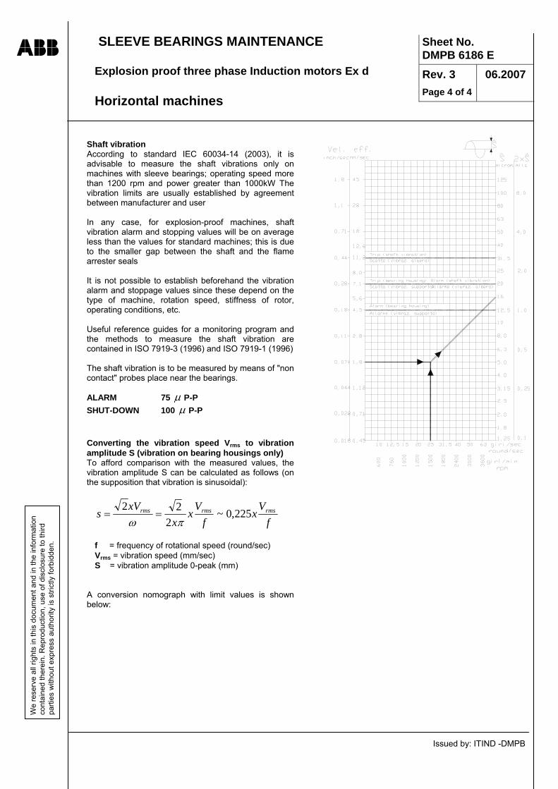
SLEEVE BEARINGS MAINTENANCE Explosion proof three phase Induction motors Ex d Horizontal machines
Issued by: ITIND -DMPB
ABB Sheet No. DMPB 6186 E
Rev. 3 Page 4 of 4
06.2007
We
rese
rve
all r
ight
s in
this
doc
umen
t and
in th
e in
form
atio
n co
ntai
ned
ther
ein.
Rep
rodu
ctio
n, u
se o
f dis
clos
ure
to th
ird
parti
es w
ithou
t exp
ress
aut
horit
y is
stri
ctly
forb
idde
n.
Shaft vibration According to standard IEC 60034-14 (2003), it is advisable to measure the shaft vibrations only on machines with sleeve bearings; operating speed more than 1200 rpm and power greater than 1000kW The vibration limits are usually established by agreement between manufacturer and user In any case, for explosion-proof machines, shaft vibration alarm and stopping values will be on average less than the values for standard machines; this is due to the smaller gap between the shaft and the flame arrester seals It is not possible to establish beforehand the vibration alarm and stoppage values since these depend on the type of machine, rotation speed, stiffness of rotor, operating conditions, etc. Useful reference guides for a monitoring program and the methods to measure the shaft vibration are contained in ISO 7919-3 (1996) and ISO 7919-1 (1996) The shaft vibration is to be measured by means of "non contact" probes place near the bearings. ALARM 75 μ P-P SHUT-DOWN 100 μ P-P
Converting the vibration speed Vrms to vibration amplitude S (vibration on bearing housings only) To afford comparison with the measured values, the vibration amplitude S can be calculated as follows (on the supposition that vibration is sinusoidal):
fV
xf
Vx
xxV
s rmsrmsrms 225,0~2
22πω
==
f = frequency of rotational speed (round/sec) Vrms = vibration speed (mm/sec) S = vibration amplitude 0-peak (mm)
A conversion nomograph with limit values is shown below:
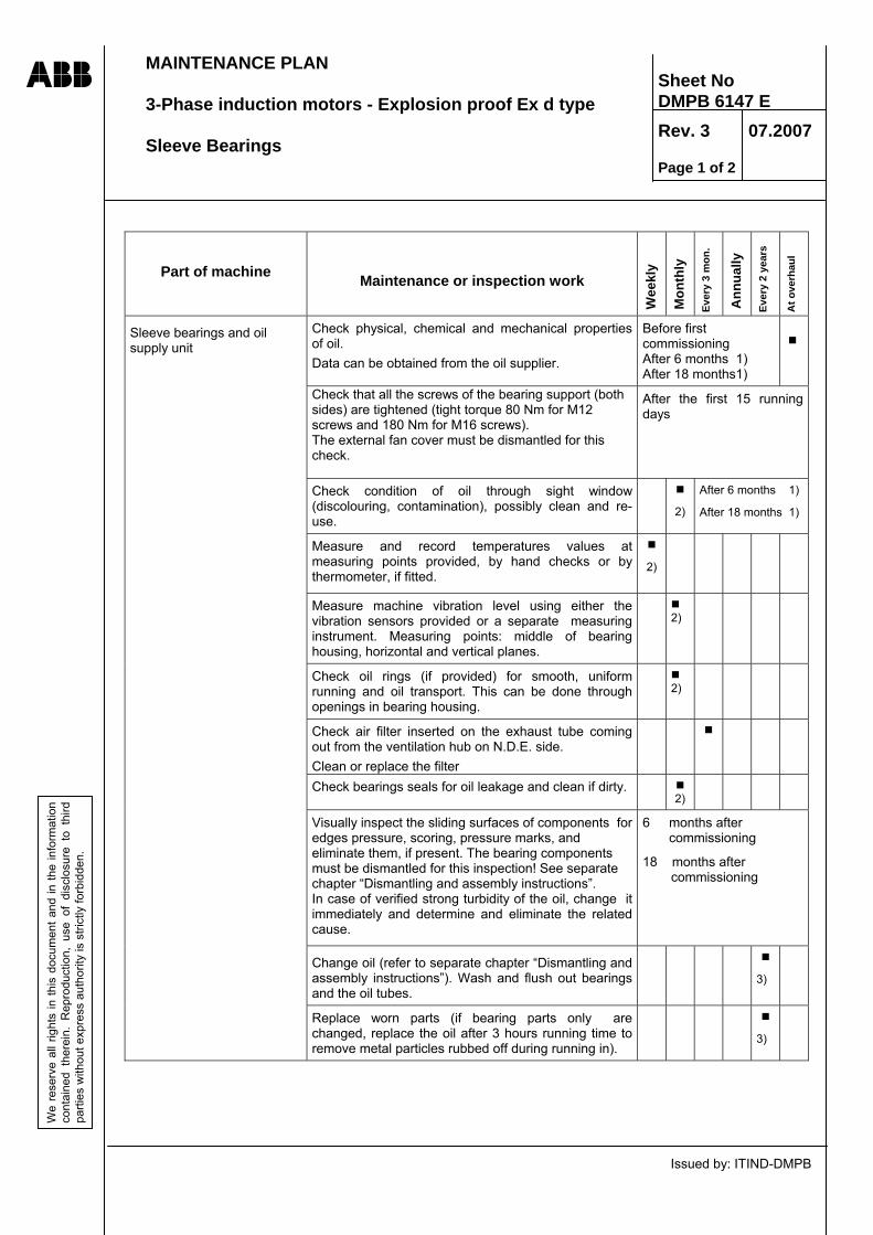
MAINTENANCE PLAN 3-Phase induction motors - Explosion proof Ex d type Sleeve Bearings
Issued by: ITIND-DMPB
ABB Sheet No DMPB 6147 E
Rev. 3 07.2007
Page 1 of 2
We
rese
rve
all r
ight
s in
this
doc
umen
t and
in th
e in
form
atio
n co
ntai
ned
ther
ein.
Rep
rodu
ctio
n, u
se o
f di
sclo
sure
to
third
pa
rties
with
out e
xpre
ss a
utho
rity
is s
trict
ly fo
rbid
den.
Part of machine Maintenance or inspection work
Wee
kly
Mon
thly
Eve
ry 3
mon
.
Ann
ually
Eve
ry 2
yea
rs
At o
verh
aul
Check physical, chemical and mechanical properties of oil. Data can be obtained from the oil supplier.
Before first commissioning After 6 months 1) After 18 months1)
Check that all the screws of the bearing support (both sides) are tightened (tight torque 80 Nm for M12 screws and 180 Nm for M16 screws). The external fan cover must be dismantled for this check.
After the first 15 running days
Check condition of oil through sight window (discolouring, contamination), possibly clean and re-use.
2)
After 6 months 1)
After 18 months 1)
Measure and record temperatures values at measuring points provided, by hand checks or by thermometer, if fitted.
2)
Measure machine vibration level using either the vibration sensors provided or a separate measuring instrument. Measuring points: middle of bearing housing, horizontal and vertical planes.
2)
Check oil rings (if provided) for smooth, uniform running and oil transport. This can be done through openings in bearing housing.
2)
Check air filter inserted on the exhaust tube coming out from the ventilation hub on N.D.E. side. Clean or replace the filter
Check bearings seals for oil leakage and clean if dirty. 2)
Visually inspect the sliding surfaces of components for edges pressure, scoring, pressure marks, and eliminate them, if present. The bearing components must be dismantled for this inspection! See separate chapter “Dismantling and assembly instructions”. In case of verified strong turbidity of the oil, change it immediately and determine and eliminate the related cause.
6 months after commissioning
18 months after commissioning
Change oil (refer to separate chapter “Dismantling and assembly instructions”). Wash and flush out bearings and the oil tubes.
3)
Sleeve bearings and oil supply unit
Replace worn parts (if bearing parts only are changed, replace the oil after 3 hours running time to remove metal particles rubbed off during running in).
3)

MAINTENANCE PLAN 3-Phase induction motors - Explosion proof Ex d type Sleeve Bearings
Issued by: ITIND-DMPB
ABB Sheet No DMPB 6147 E
Rev. 3 07.2007
Page 2 of 2
We
rese
rve
all r
ight
s in
this
doc
umen
t and
in th
e in
form
atio
n co
ntai
ned
ther
ein.
Rep
rodu
ctio
n, u
se o
f di
sclo
sure
to
third
pa
rties
with
out e
xpre
ss a
utho
rity
is s
trict
ly fo
rbid
den.
Part of machine Maintenance or inspection work
Wee
kly
Mon
thly
Eve
ry 3
mon
.
Ann
ually
Eve
ry 2
yea
rs
At o
verh
aul
Check for rust.
4)
Before first commissioning Sleeve bearing with insulated shells
(only horizontal machines)
Check bearing shell insulation.
2)
Oil supply unit Check oil supply unit with regard to following: Proper operation Oil level, leakage incl. bolted connections, seals on bearing oil piping . Clean filter.
On indication from filter monitor
1) Applicable to obtain information if the oil change intervals have to be extended. This is practical if large oil quantities are involved.
2) Compare with earlier measurements and observations.
3) After 8000 hours of operation or 2 year at the least. This often applies to stationary machines too.
4) Remove possible rust using a fine oil stone. Where painting is not possible, coat bare surface with anticorrosion covering.

MAINTENANCE Explosion proof Three Phase Induction motors Ex d Type Cleaning of mechanical components
Issued by: ITIND-DMPB
ABB W
e re
serv
e al
l rig
hts
in th
is d
ocum
ent a
nd in
the
info
rmat
ion
cont
aine
d th
erei
n. R
epro
duct
ion,
use
of d
iscl
osur
e to
third
pa
rties
with
out e
xpre
ss a
utho
rity
is s
trict
ly fo
rbid
den.
Sheet No. DMPB 6188 E Rev.2 Page 1 of 2
06.2007
WARNING! Dismantling and reassembling the explosion proof equipments (Ex d) requires qualified personnel.
General Form of the components Before beginning with the cleaning work, the machine should be partially dismantled as far as practical (covers, bearing endshields, bearings, rotor etc.). The item to be cleaned should always be stripped down into easily manageable components conveniently accessible from all sides. Special machine components Components of austenitic steel (Cr-Ni alloy, non-magnetic, corrosion resistant) subject to tensile stressing e.g. rotor shrink rings, can, in unfavourable cases, be destroyed by stress corrosion if halogens cleaning solvents are employed. Therefore, electrical machines should only be cleaned with non-halogens solvents. Cleaning methods Mechanical dry cleaning To begin with, one should as a matter of principle always employ a mechanical cleaning method (scrapers, hard brushes, vacuum cleaners) to “get the worst off” or as the main cleaning method. Only vacuum cleaners with soft suction nozzles of rubber or plastic should be used. Wet cleaning Wet cleaning methods should only be used for the main cleaning, or for final cleaning after thorough application of a mechanical cleaning method. The reason for this is to prevent or at least reduce to a safe minimum, undesirable and dangerous dirt displacement which is liable to take place during wet cleaning. Standard cleaning agent (industrial benzene) This cleaning agent should be used for ordinary dirt (dust, oil, slight to medium soot deposits after fire). Special cleaning agent (Xylene) Xylene (higher aromatic value than industrial benzene) may be required to deal with very gummy oil. It is usually also the only effective remedy for the sticky gummy deposits found in a machine which has been on fire.
In any case the following cautions are needed : - The working area should be provided with
particularly efficient ventilation to safeguard health and as a precaution against fire.
- The standard relevant safety work must be applied.
Wet cleaning method Standard cleaning method (brush/cloth) Using the brush the cleaning agent can only be applied in relatively small amounts, but it is used to the utmost for absorbing the dirt. This is the standard cleaning method, whereby the cleaning agent is applied to the dirt with a hard paintbrush in small successive stages and the dissolved dirt immediately wiped off with a clean, dry cloth, before it has time to start drying or running off. Only a small quantity of solvent which can be quickly used up is prepared in a small clean tin. Consequently the solvent quickly becomes contaminated from the dirty brush and must be changed very frequently, which also helps to reduce the fire hazard. A further important point upon which the effectiveness of this method depends is that only fresh, clean, non-fraying and non-fluffing cloths be used and frequently changed. This requirement must be strictly observed. Instead of using a large piece of cloth over and over again as customary, several small pieces should be prepared and used only two or three times and then thrown away. This also helps to prevent dirt from being returned to surfaces being cleaned. Special cleaning methods (Spray and jet methods) Spray and pressure-jet methods may be a more rational solution where conditions are suitable. Conventional mobile equipment using aqueous cleaning agents are available on the market for pressures up to 90 bar and with heating arrangements for up to 80°C or steam up to 140°C. This method can seldom be used on permanently installed machines, because of the difficulty of providing an adequate drainage for the substantial quantity of dirty washing solvent produced. Before deciding to use any of the special methods available, it must always be carefully considered whether the design features of the machine are suitable for such an application. In addition, the technical department responsible for the machine and the laboratory specialist should be consulted.

MAINTENANCE Explosion proof Three Phase Induction motors Ex d Type Cleaning of mechanical components
Issued by: ITIND-DMPB
ABB W
e re
serv
e al
l rig
hts
in th
is d
ocum
ent a
nd in
the
info
rmat
ion
cont
aine
d th
erei
n. R
epro
duct
ion,
use
of d
iscl
osur
e to
third
pa
rties
with
out e
xpre
ss a
utho
rity
is s
trict
ly fo
rbid
den.
Sheet No. DMPB 6188 E Rev.2 Page 2 of 2
06.2007
Cleaning agents Only the agents permitted by the manufacturer are to be used for wet cleaning. Industrial benzene (non-halogens, low volatility, inflammable) = Standard cleaning agent Properties (from delivery specification) Density 0.78 … 0.8 g/cm³ Boiling range 135 … 200°C Abel-Pensky flash point 21°C - Danger class to DIN 51755 : A II - CEA Classification : Fe II B - Swiss toxicity class : 4 … 5 depending on aromatic content Xylene CHR (chemically pure) = Special cleaning agent (non-halogens, medium volatility, inflammable) Properties (from delivery specification) Composition Mixture of o-, m- and p-dimethylbenzol Density 0.864 … 0.872 g/cm³ Boiling range 137 … 143°C Abel-Pensky flash point 20 … 25°C - Danger class to DIN 51755 : A I - CEA Classification : FE II B Fu Other comparable and permissible products and suppliers:
Supplier Trade name Boiling range °C
Flash point °C
Evaporation no. (ether = 1)
Aromatic content %
Shell Sangajol 154-201 35 75 35 Exxon Varsol 155-185 38 55 18 BP White Spirit 35 150-200 40 60 35 Mobil Oil White Spirit 157-196 41 - 18 Chevron White Spirit 162-196 35 75 35 Valvoline White Spirit 160-200 40 60 25 Castrol White Spirit 155-187 38 55 18 The following cleaning agents are not allowed ! Trichloraethane (halogens, incombustible) Trade names: Clorothene, Genklene, Solvethane, Baltane. When ignited from an extraneous source the above release highly toxic, corrosive decomposition by products. Their use in electrical machines is therefore strictly prohibited. Trichloroethylene, perchloroethylene
(halogens, incombustible) The same disadvantages as trichloroethane, plus higher toxicity. Not released by health authorities. Swiss toxicity class: Trichlo. 4, Perchlo.5 “Safety” solvents Trade names: Pentex 77, SS 26 Turco-Solv, Diluan T, Disolver Gamlen-Solvent 26 Inner-El-Mot-Cleaner, etc. The claim to additional safety is mainly based on the higher flash point of these products. Since they also
dry very quickly however, consumption rates are appreciably higher, resulting in heavier contamination of the work-shop atmosphere. All “safety” solvents contain varying proportions of halogens solvents and therefore are not to be used for the same reasons. Fluorinated solvents (halogens, incombustible) Trade names: Freon-TF (Du Pont) Flugene (Rhone-Poulenc) General use of these products is strictly prohibited. They may only be used in special cases by qualified specialists. Non-halogens, volatile solvents Examples: Acetone, Nitro-thinner, Volatile benzene Use of these products is prohibited, on account of the fire and explosion hazard.
ABB Maintenance of medium voltage windings
Issued by ITIND - DMPB
Sheet No DMPB 6189 E Rev. 2 Page 1 of 4
07.2003
We
rese
rve
all r
ight
s in
this
doc
umen
t and
in th
e in
form
atio
n co
ntai
ned
ther
ein.
Rep
rodu
ctio
n, u
se o
f dis
clos
ure
to th
ird
parti
es w
ithou
t exp
ress
aut
horit
y is
stri
ctly
forb
idde
n.
Maintenance of the windings The maintenance of medium voltage windings (i.e. rated voltage of the motor between 1,5 and 12 kVolt) requires the following actions (see relevant Sheet): • regular check of the winding temperature by means of the temperature detectors inserted between the coils. An abnormal difference between the detected temperatures can indicate an incipient fault or a problem of poor dissipation of the heat generated by the circulation of current. When such a situation would arise, further inspections and diagnosis could be necessary to clarify the problem. • Measurement of the insulation resistance
(suggested every three months, but at least one time per year).
The measurement technique is described on the relevant Sheet, together with some indication of the acceptable values. It is important to remember that the insulation resistance values are not correlated in any way with the actual dielectric strength of the insulation, but only supply information on wetness and degrees of contamination of the insulation itself. The a.m. information is very useful for scheduling the possible cleaning and drying actions. In any case the most important parameter for the judgment is the comparison of the measured value with the previous measurements. Remember, for the comparison purpose, to take always into account the effect of the temperature on the measured insulation resistances, so take and record every time the winding temperature. In case the disconnection of the motor terminals from the feeding cables would be a problem, it is possible to carry out the measurement including even the insulation resistance of the cables, if their dielectric condition can be considered safe and sound. It is also common to take into account the “Polarization Index” that is the ratio between the insulation resistance value taken after 1 minute from the application of the direct voltage to the object under test and the same value taken after 10 minutes from the application of the voltage. R 1min PI = --------- R10min
The advantage given by the Polarization Index is its independence from the temperature, at least for windings temperature lower than 50°C (122°F). The PI normally ranges from 1 to 4÷6; When the winding is humid and dirty the PI is near 1, whereas when the winding is in normal condition the PI is at least around 2÷2,5. It is important to note that occasionally the PI can give misleading values; sometime very low PI values were measured on modern epoxy-mica insulation, although the windings have been dry and the insulation resistance very high (thousands of MΩ). So when estimating the situation of a winding, the insulation resistance value has to be considered more important than the PI. • Internal visual inspection of the winding at overhaul.
A dielectric condition diagnosis is suggested at overhaul.
Visual inspection The winding visual inspection reveal information about:
The rate of contamination for presence of dirt and humidity.
The condensation of humidity inside the motor. The mechanical stability of the winding. The possible overheatings (generalised or local)
It is strongly suggested that the results of every inspection should be recorded. When examining the winding the following points have to be remembered: The dirt accumulated on the windings’ overhangs can close the spaces between the coils, diminishing the cooling capacity of the machine. As a result the winding temperature on load increases, with consequent acceleration of the winding's ageing. Mechanical strain, vibration and shocks may produce cracks near the retaining support of the coils or around the core slot edges. Loose supports or moving slot wedges are sign of deterioration too. Abrasion marks or presence of yellow powder near the retaining supports and slot ends must be checked and investigated. Complete loosening of slot wedges or bent coils are serious problems, that must be rectified immediately. On the contrary, the loosening of few magnetic wedges (if any) is not a serious problem, providing that the loosing process would not be continuous; the motor can work without problems even with some loosen magnetic wedges. The replacement of the loosen wedges can even be scheduled at the following overhaul. Humidity on the winding is shown by the marks it leaves behind, like rust on iron components, drop marks, and wetting marks on dirt layers. Signs of tracking current on the coils’ surface with “bush” patterns and charred residues are sign of probable incipient failure and their reason must be investigated and resolved.

ABB Maintenance of medium voltage windings
Issued by ITIND - DMPB
Sheet No DMPB 6189 E Rev. 2 Page 2 of 4
07.2003
We
rese
rve
all r
ight
s in
this
doc
umen
t and
in th
e in
form
atio
n co
ntai
ned
ther
ein.
Rep
rodu
ctio
n, u
se o
f dis
clos
ure
to th
ird
parti
es w
ithou
t exp
ress
aut
horit
y is
stri
ctly
forb
idde
n.
Very noticeable are the effects of short period strong overloading or fault condition that can produce localised overtemperatures. This condition leaves characteristic marks all over the machine. The copper of the rotor cage grows darker ad become oxidised. The rotor core laminations become blue if the temperature has reached 350°C (this can also be the effect of very heavy startings). Localised overtemperatures in the stator can produce thermal expansion very dangerous for the winding coils whose insulation can crack.
The effect of prolonged period overtemperatures, caused by continuous overloading or incorrect dissipation of the heat, is the premature ageing of the insulation. The insulation materials become brittle and change colour to darker appearance; moreover fractures and splits of insulating layers can be produced.
Conclusion from the visual inspection. According to the observed situation of the winding, the following conclusions can be drawn, and the consequent actions are suggested to be taken
Observation Action
Degree of contamination: • Presence of dirt, cooling ducts about to be
plugged. • Conductive dirt, low insulation resistance • Humidity, low insulation resistance
• Cleaning and drying, if necessary • Cleaning and drying, if necessary • Drying
Finishing varnish • Mat, worn, cracked • Coming off Winding and supporting elements • Loose slot wedges • Slot wedges coming off • Vibration marks • Bent coils Insulation ageing • Darkening, slight embrittlement • Embrittlement, loose insulation layer
• Cleaning and re-varnishing • Remove old varnish and re-varnish • Tightening *) • No action if less than 10%. Replacement if
more *) • Tightening, strengthen and re-varnish *) • Strengthen or re-do the winding *) • Cleaning and re-varnishing • Re-do the winding *) A statement of an expert is absolutely needed
Cleaning and drying the windings. The cleaning, drying and refurbishment of the windings is matter of specialist and must be carried out by trained and experienced people, preferably under the supervision of a qualified Service organisation.
Cleaning methods. Blowing and vacuuming Blowing and vacuuming are used if the dirt is dry and can be removed easily. Vacuuming is the preferred method, since blowing tends to redistribute the dirt or move it deeper between the insulation layers.

ABB Maintenance of medium voltage windings
Issued by ITIND - DMPB
Sheet No DMPB 6189 E Rev. 2 Page 3 of 4
07.2003
We
rese
rve
all r
ight
s in
this
doc
umen
t and
in th
e in
form
atio
n co
ntai
ned
ther
ein.
Rep
rodu
ctio
n, u
se o
f dis
clos
ure
to th
ird
parti
es w
ithou
t exp
ress
aut
horit
y is
stri
ctly
forb
idde
n.
Spray-wash. The spray-wash is usually carried out with a conventional spray or with an airless high-pressure spray. The high-pressure spray is more effective in removing dirt. If a detergent agent is used, it should remove the dirt without softening or damaging the insulation. Dip wash. The winding is completely immersed into the detergent agent. Since with this method the dirt is not removed mechanically, a very effective cleaning and scouring agent is needed, and a long dipping time may be required. Be sure that the detergent does not soften or damage the insulation. Wiping. Wiping is used when spray-wash is not possible. The surfaces easily reached are wiped clean with a cloth dampened with detergent. In cramped areas of the winding, a special brush may be more effective. Water wash The water wash is usually required after one of the cleaning method described above, in order to remove the detergent residues and prevent these from penetrating into places where they cannot be removed. After cleaning the winding is rinsed with pure water several times. It is recommended to use distilled water or deionized water for the last rinse. Drying after the water wash is necessary. Detergent agents. Refer for further details to the Sheet DMPB 6188 E. Before any detergent agent is used, its possible damaging effect on the old winding surface should be checked. A suitable test can be performed as follows: Using a piece of cloth wet with the detergent, rub the surface to be tested for about five minutes. Make sure that the surface remains completely wet during this time. After rubbing, try to remove the finishing varnish of the windings by the thumb nail. Do the same thing on a dry part of the surface, for comparison. If the surface layer is soft or can be removed easily, the detergent agent is too strong. For minimal environmental loading, water should be used, if the dirt is soluble in water. If the dirt contains grease components, detergents that improve the cleaning power can be added to the water. Make sure that these detergents do not leave electrically conductive residues on the windings surfaces. Some detergents are soluble in
water, like acetone or isopropyl alcohol, and are effective for this purpose. Remember that these solvents are highly inflammable and must be used with the proper precautions. If organic solvents must be used as detergent agents, only solvents based on aliphatic hydrocarbons are recommended. Use detergent agents halogen-free and without chlorinated components. White spirit is the most common organic solvent. It is effective for grease, but unfortunately quite inefficient for bitumen-like dirt that can be produced on the windings by the burning residues of fires. Drying. The windings must be dried after a wash or if they have become humid in use or following a long standstill. A wet motor should be dismantled and the winding possibly dried in the oven. In case the motor is not very wet, the winding can be dried by passing current through it by means of a low voltage-high current device like a welding generator.
Remark! When electric current is used for drying the winding, the rotor must be first removed from the motor. DC or AC current can be used. Current intensity cannot exceed 25% of the rated current value indicated on the nameplate of the motor.
The rate of temperature rise during the heating should not exceed 5°C (9°F) per hour, and the final temperature should not exceed 105°C (220°F). A sudden temperature rise or a final temperature too high, can cause steam to be formed in the cavities of the windings, which in turn can damage the insulating barrier. During the drying process the temperature should be monitored periodically, and the insulation resistance measured at regular intervals. When drying in an oven, set the oven temperature at 90°C (194°F) for 12 to 16 hours and then to 105°C (220°F) for further 6 or 8 hours. Effective drying is achieved with proper balance of heat and ventilation. The air inside the machine should be circulated in the most effective way. This is usually obtained using a ventilated oven. In case the winding would be heated with current or with hot-air blower, ensure an adequate fresh air exchange along the winding. The drying of the windings should be followed by insulation resistance measurements. At the

ABB Maintenance of medium voltage windings
Issued by ITIND - DMPB
Sheet No DMPB 6189 E Rev. 2 Page 4 of 4
07.2003
We
rese
rve
all r
ight
s in
this
doc
umen
t and
in th
e in
form
atio
n co
ntai
ned
ther
ein.
Rep
rodu
ctio
n, u
se o
f dis
clos
ure
to th
ird
parti
es w
ithou
t exp
ress
aut
horit
y is
stri
ctly
forb
idde
n.
beginning of the drying treatment the insulation resistance value decreases due to temperature rise. As the drying continues, however, the insulation resistance increases until it reaches a stable value. Varnishing of the windings. The windings’ surfaces are normally coated with a protective layer that seals the windings, improve somewhat the tracking resistance and makes cleaning easier. This is obtained by spraying or brushing a finishing varnish or resin on the exposed area of the winding. The finishing varnish may, after long operating time crack or peel off to certain extent. This can be corrected by giving on the damaged surfaces a new coat of varnish. This is recommended when: • The old finishing varnish flakes, cracks or
peels off. • The surface of the winding is too rough (the
dirt can stick to it) • The materials on the surface of the insulation
or the tyings on the overhangs have moved. The windings should be cleaned with utmost care before a new coat of varnish is given, in order to be sure that no dirt will be left under the new coat of varnish. The varnish is usually applied with a spray (one or two coat). Do not apply the varnish if the winding is warm; the surface temperature should be less than 40°C (104°F). One should try to apply the varnish between the coils and in general between the parts that are not easily reached. Thick coat of varnish should be avoided as they dry slowly. Rotating parts should be left to dry at least 24 hours at ambient temperature before bringing them into use. Voltage test. A voltage test is used to check for electrically weak spots in the windings that may lead to insulation failure during servicing. It is the only test that can give information about the soundness of the insulation barrier; anyway the decision about the application of high voltage to an old winding is matter of specialist. This test is carried out during repair or, depending on the situation, during overhauls. DC or AC voltage can be used; DC is seldom used for the sizes of machines as treated in this manual and involves the application of a voltage that is 1,6 times the root-mean-square value of the AC test voltage.
The suggested values for voltage tests, carried out with AC are: for service and repair 1,5 x U for periodical test during overhaul 1,25 x U where U is the rated voltage of the motor. Work safety principles during winding maintenance. Winding maintenance involves: • Handling hazardous solvents, varnishes and
resins. • Dealing with flammable solvents and
varnishes. • Testing at high voltage. Some general safety measures are remembered as follows:
Avoid breathing dangerous substances fumes; ensure proper air circulation at the work site and use respiration masks.
Wear gloves and suitable clothing to protect the skin. Use always protective cream
The frame of the machine, the windings terminals and the spray-varnish equipments should always be earthed during spray-varnishing.
Do not smoke, eat or drink at the work site. Take the necessary precaution when working
in cramped spaces. Only people trained to do high voltage works
can carry out a voltage test. In any case refer to all the instruction available on the working area and to the national rules of the Country where the job is in progress. Look also to the handling instructions that are printed on the warning labels of the dangerous substances packing.

Asynchronous motors explosion proof Ex d - Gas group IIB AMDR type - Size 355 - 500
Section 4
Machine dismantling and assembling

Dismantling and Assembly Instructions Asynchronous motors, type AMDR rib cooled Explosion proof Ex d type Group II B Horizontal shaft design - Size 355 to 500 Grease-lubricated antifriction bearings
Issued by: ITIND-DMPB
ABB W
e re
serv
e al
l rig
hts
in th
is d
ocum
ent a
nd in
the
info
rmat
ion
cont
aine
d th
erei
n. R
epro
duct
ion,
use
of d
iscl
osur
e to
third
pa
rties
with
out e
xpre
ss a
utho
rity
is s
trict
ly fo
rbid
den.
Sheet No DMPB 6159 E Rev. 3 07.2007 Page 1 of 4
General arrangement
REMARK : the sketch represents the typical outline and internal view of the main components for purpose of assembling and disassembling guide. Some details of the actual motor (i.e external fan, bearings enclosure etc.) can have different technical solutions, or additional equipment can be provided, without change of the disassembling and assembling operations sequence. Always refer to the specific documentation of the order for more details. In case of doubt contact the manufacturer or an ABB Service factory.
Main terminal box Auxiliary terminal box
External fan
Fan cover
Drive end side Non-Drive end side

Dismantling and Assembly Instructions Asynchronous motors, type AMDR rib cooled Explosion proof Ex d type Group II B Horizontal shaft design - Size 355 to 500 Grease-lubricated antifriction bearings
Issued by: ITIND-DMPB
ABB W
e re
serv
e al
l rig
hts
in th
is d
ocum
ent a
nd in
the
info
rmat
ion
cont
aine
d th
erei
n. R
epro
duct
ion,
use
of d
iscl
osur
e to
third
pa
rties
with
out e
xpre
ss a
utho
rity
is s
trict
ly fo
rbid
den.
Sheet No DMPB 6159 E Rev. 3 07.2007 Page 2 of 4
Bearings arrangements
insulating layer and insulating
washers
Example of insulated bearing
1
Ball bearing D.E. side and
N.D.E. side for 4 and more poles
5
1
10
14
Roller bearing N.D.E. side for 2 poles motor
insulating layer and insulating washers
5 14 10
4
5
1
4
14
13 13

Dismantling and Assembly Instructions Asynchronous motors, type AMDR rib cooled Explosion proof Ex d type Group II B Horizontal shaft design - Size 355 to 500 Grease-lubricated antifriction bearings
Issued by: ITIND-DMPB
ABB W
e re
serv
e al
l rig
hts
in th
is d
ocum
ent a
nd in
the
info
rmat
ion
cont
aine
d th
erei
n. R
epro
duct
ion,
use
of d
iscl
osur
e to
third
pa
rties
with
out e
xpre
ss a
utho
rity
is s
trict
ly fo
rbid
den.
Sheet No DMPB 6159 E Rev. 3 07.2007 Page 3 of 4
Important! Explosion-proof Ex d motors should be serviced, following the proper instructions, only by trained and certified personnel, preferably under the supervision of ABB Service organisation. Maintenance operations must comply with the rules specified in the EN/IEC 60079-17 and 60079-19 Standards.
Dismantling the machine The following sequence of operations refers to the usual maintenance jobs that can be required during overhauls. − Disconnect all cables and leads from power
supply, instrumentation, monitoring equipment and earthing. Remove or loosen the grease filling tubes
− Remove the N-end mounted fan covers and external fan. Remove the temperature sensors and auxiliary devices, if any.
− Remove the machine holding-down bolts and dowel pins (if any) and uncouple the shaft from the driven machine.
− Pull off the coupling hub from shaft extension (see sheet DMPB 6173 E). If the machine is provided with a coupling at each end, remove both.
− Remove the snap circlips (10) with the special pliers.
− Pull off the rotating labyrinth seals (14) including the rotating grease valve of both sides using suitable threaded rods; these components are fitted with slight interference on the shaft, so it advisable to heat them up to about 80°C (176°F) using suitable tools before pulling (some solution have the labyrinth seal separated from the grease rotating valve). Remove the screws (4) and the outer bearing covers (13).
− Sustain the rotor on one side (preferably D.E. side) using a crane or a liftjack, and relieve the rotor weight from the bearing. Provide a solid support to release the shaft end on it.
− Remove the bolts (15) which connect the endshield (16) to the stator frame. Secure the endshield to its top centre by using an eyebolt
− Pull off the endshield from the stator frame (side of the loosen shaft) by using two suitable bolts inserted into the threaded holes provided in the endshield. The endshield (16) can now be carefully leaned on the shaft. At this stage the bearing (1) remains shrunk on the shaft and the flame arresters (5) remain in place.
− Repeat the same steps in order to release the other endshield.
− Protect the exposed parts of the bearings by wrapping them in waxed paper or clean cloth.
− Insert presspan or pressboard protections into the stator bore, between the stator and rotor magnetic cores.
− Using again the crane or the liftjack, lift the rotor sufficiently to remove the solid supports sustaining the (D.E.) shaft ends and lean the rotor on the stator core through the pressboard protections inserted.
− Remove the endshields from the rotor. − Fit a pressboard protection wrapped around
one of the shaft extension. Slip over the protection a steel tube of proper diameter in order to obtain a shaft extension and using a proper device set (preferably based on cranes) withdraw the rotor from the stator bore. Rotor withdrawal requires a free space approximately equal to the machine length.
Important: during the a.m. operations pay attention to avoid any shock that can damage the inner surface of the stator bore, the electric connections and the flame arresters. - Removal and reassembling of bearings from
the shaft must be made using particular care. To pull out the bearings use an adequate bearing withdrawal tool set, which apply pressure only on the inner bearing ring. Remember that the fit between the shaft and the inner ring is tight to prevent the rotation of the bearing on the shaft during the operation. Insulation of bearing (if any) is obtained with a layer of special material fitted in the endshield inner bore and two insulating washers. Take care of this parts during disassembling.
- Check the flame arresters surfaces that must be free of burrs or signs of any contacts with the shaft during the rotation.
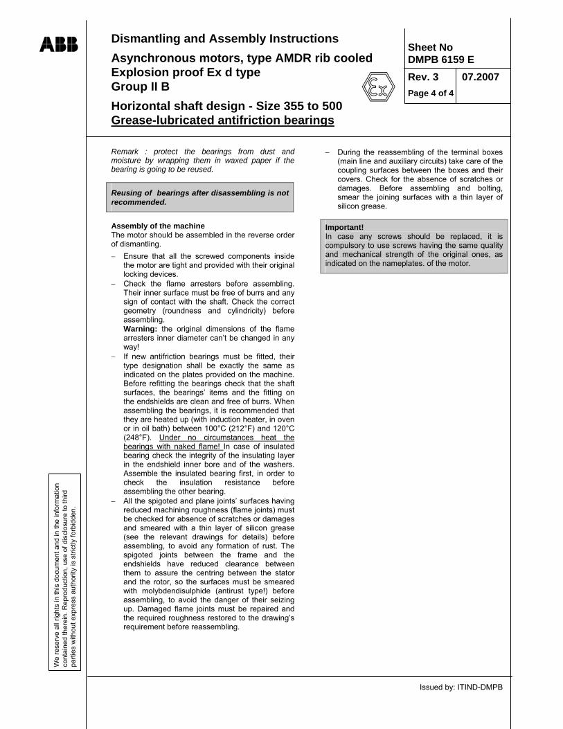
Dismantling and Assembly Instructions Asynchronous motors, type AMDR rib cooled Explosion proof Ex d type Group II B Horizontal shaft design - Size 355 to 500 Grease-lubricated antifriction bearings
Issued by: ITIND-DMPB
ABB W
e re
serv
e al
l rig
hts
in th
is d
ocum
ent a
nd in
the
info
rmat
ion
cont
aine
d th
erei
n. R
epro
duct
ion,
use
of d
iscl
osur
e to
third
pa
rties
with
out e
xpre
ss a
utho
rity
is s
trict
ly fo
rbid
den.
Sheet No DMPB 6159 E Rev. 3 07.2007 Page 4 of 4
Remark : protect the bearings from dust and moisture by wrapping them in waxed paper if the bearing is going to be reused.
Reusing of bearings after disassembling is not recommended.
Assembly of the machine The motor should be assembled in the reverse order of dismantling. − Ensure that all the screwed components inside
the motor are tight and provided with their original locking devices.
− Check the flame arresters before assembling. Their inner surface must be free of burrs and any sign of contact with the shaft. Check the correct geometry (roundness and cylindricity) before assembling. Warning: the original dimensions of the flame arresters inner diameter can’t be changed in any way!
− If new antifriction bearings must be fitted, their type designation shall be exactly the same as indicated on the plates provided on the machine. Before refitting the bearings check that the shaft surfaces, the bearings’ items and the fitting on the endshields are clean and free of burrs. When assembling the bearings, it is recommended that they are heated up (with induction heater, in oven or in oil bath) between 100°C (212°F) and 120°C (248°F). Under no circumstances heat the bearings with naked flame! In case of insulated bearing check the integrity of the insulating layer in the endshield inner bore and of the washers. Assemble the insulated bearing first, in order to check the insulation resistance before assembling the other bearing.
− All the spigoted and plane joints’ surfaces having reduced machining roughness (flame joints) must be checked for absence of scratches or damages and smeared with a thin layer of silicon grease (see the relevant drawings for details) before assembling, to avoid any formation of rust. The spigoted joints between the frame and the endshields have reduced clearance between them to assure the centring between the stator and the rotor, so the surfaces must be smeared with molybdendisulphide (antirust type!) before assembling, to avoid the danger of their seizing up. Damaged flame joints must be repaired and the required roughness restored to the drawing’s requirement before reassembling.
− During the reassembling of the terminal boxes (main line and auxiliary circuits) take care of the coupling surfaces between the boxes and their covers. Check for the absence of scratches or damages. Before assembling and bolting, smear the joining surfaces with a thin layer of silicon grease.
Important! In case any screws should be replaced, it is compulsory to use screws having the same quality and mechanical strength of the original ones, as indicated on the nameplates. of the motor.

Disassembly and assembly instructions Explosion-proof asynchronous motors, type AMDR with rib cooling Ex d Group II B Horizontal axis Oil lubricated DIN-EF sleeve bearings
Issued by: ITIND - DMPB
ABB Sheet No. DMPB 6140 E Rev. 4 06.2007 Page 1 of 5
We
rese
rve
all r
ight
s in
this
doc
umen
t and
in th
e in
form
atio
n co
ntai
ned
ther
ein.
Rep
rodu
ctio
n, u
se o
f dis
clos
ure
to th
ird
parti
es w
ithou
t exp
ress
aut
horit
y is
stri
ctly
forb
idde
n.
Sleeve bearing details
Detail of the inner labyrinth flame seal
Labyrinth flame seal
INNER of MOTOR

Sheet No. DMPB 6140 E
Rev. 4 06.2007 Page 2 of 5
Disassembly and assembly instructions Explosion-proof asynchronous motors, type AMDR with rib cooling Ex d Group II B Horizontal axis Oil lubricated DIN-EF sleeve bearings
Issued by: ITIND - DMPB
ABB W
e re
serv
e al
l rig
hts
in th
is d
ocum
ent a
nd in
the
info
rmat
ion
cont
aine
d th
erei
n. R
epro
duct
ion,
use
of d
iscl
osur
e to
third
pa
rties
with
out e
xpre
ss a
utho
rity
is s
trict
ly fo
rbid
den.
Important! Explosion-proof motors should be serviced, following the proper instructions, only by trained and certified personnel, preferably under the supervision of ABB Service organization. Maintenance operations must comply with the rules specified in the EN/IEC 60079-17 and 60079-19 Standards.
Machine disassembly The following sequence of operations applies to the usual maintenance jobs, that can be required during the overhauls. − Disconnect all cables and leads for power supply,
instrumentation, monitoring equipment and earthing. Drain oil from both bearings. If the bearings have a separate flood-oil supply, disconnect the oil feed and return lines.
− Remove the N-end mounted fan cover, external fan, temperature sensors and auxiliary devices, if any.
− Remove the machine holding-down bolts and any dowel pins (if any), then uncouple the shaft.
− Pull the coupling hub from the shaft extension (see Sheet DMPB 6173 E). If the machine has a coupling at each end, remove both.
− Remove the bolts (1), which connect the flange of the bearing housing top part (2) at the bearing endshield (3).
− Remove bolts (4) and cylindrical pins (5) at the split of the bearing housing top part.
− Remove the bolts (7), which connect the bearing housing top part and detach the oil seal (8) and cover (9) from the housing. Carefully raise the bearing housing top part (2) just enough for the housing joint to open evenly, then swing it out of the bearing endshield (3) and lift it off. Use the eyebolts on top of the bearing housing top part (2) for lifting!
− Remove both halves of the oil seals (8). − Dismantle the shaft oil seals (10) and (11). For
this purpose slightly pull up the relevant upper halves and tilt until the garter spring (12) can be unlatched.
− Open the garter spring (12) by turning left on the lock and carefully remove the lower half of the seal.
− Mark the assembly position of the bearing shell top part (13) and take it off carefully.
− Remove the bolts of the loose oil ring (14) and carefully handle the two halves in a way not to affect their true geometric shape.
− Disconnect the thermometers and other instruments, if any.
− Raise the shaft (lifting point = middle of the shaft extension) by only one or two tenth of a millimeter just enough to relieve the bearing shell bottom part (15). Pay attention: the air gap between the flame arrester (18) and the shaft is only few tenths of millimeters! Protect the shaft extensions before you attach the lifting means to the shaft. If necessary, extend the shaft by means of bolted extensions. After raising the shaft, hold the shaft in position with wooden blocks, so you can use the crane for further work. Repeat the operations on both sides.
The disassembly work described below must be done at N.D.E. first!
− Turn the bearing shell part (15) until it can be removed. Lift it by using eyebolts in the threaded holes at the bottom and remove.
− Now dismantle the bottom half of the bearing housing (6) and bolts (16). The bottom half housing is centered and secured to the endshield by two conical pins, that must be removed. Take care of the correction thickness for axial and radial centering of the bearings, of the following types: for axial centering (magnetic centering
between stator and rotor) some ring shaped thickness can be inserted between the bearing and the endshield.
for radial centering some brass thickness can be glued upon the fitting of the bearing provided on the endshield.
Take good note of these centering thickness, and if the removal is necessary mark them in a way that permits their exact reposition on site during the reassembling of the machine.
− Release the labyrinth flame arrester (18) by loosing the relevant screws. REMARK: Between the flame seal and its fitting on the endshield some annular thicknesses can be inserted, to obtain the axial centering of the flame seal against the labyrinth ferrule provided on the shaft.

Sheet No. DMPB 6140 E
Rev. 4 06.2007 Page 3 of 5
Disassembly and assembly instructions Explosion-proof asynchronous motors, type AMDR with rib cooling Ex d Group II B Horizontal axis Oil lubricated DIN-EF sleeve bearings
Issued by: ITIND - DMPB
ABB W
e re
serv
e al
l rig
hts
in th
is d
ocum
ent a
nd in
the
info
rmat
ion
cont
aine
d th
erei
n. R
epro
duct
ion,
use
of d
iscl
osur
e to
third
pa
rties
with
out e
xpre
ss a
utho
rity
is s
trict
ly fo
rbid
den.
− Remove the bolts (17) which connect the endshield (3) with the stator frame. Secure the bearing endshield (3) to its top centre by using an eyebolt.
− Pull off the bearing endshield (3) from the stator frame by using 2 bolts in the threaded holes of the endshield.
− The bearing endshield can now be carefully leaned on the shaft.
− Repeat the same steps in order to remove the other endshield (DE).
− Insert presspan or pressboard into the stator bore, between the stator and rotor magnetic cores, working from the NDE side.
− Using again the crane, lift the rotor sufficiently to remove the wooden blocks and lean the rotor on the stator core through the pressboard protections inserted.
− Remove the labyrinth flame seals, marking with care the annular thicknesses provided for the axial centering (if any) in order to reassemble them exactly as they originally were.
− Remove the endshields from the shaft. − Fit a presspan or pressboard protection wrapped
around the D-end shaft extension. Slip over the protection a steel tube of proper diameter to have a shaft extension and with this withdraw the rotor from the stator bore traveling from the DE towards the NDE. This work could be done by using two cranes or by other mobile adapted machines. Rotor withdrawal requires a free space approximately equal to the machine length.
Important: During the a.m. operations pay attention to avoid any shock that can damage the inner surface of the stator bore, the electric connections and the flame arresters. Visual checks of sleeve bearings and flame arrester components
When dismantling the individual components check that all running surfaces are in perfect conditions, taking into consideration the period of operation. The bearing shell should show a uniform wear pattern. Possible scorings should be smoothed before reassembling. Damages to the white metal lining, i.e. wiping and white metal built-up, are not allowed. The causes shall be investigated and removed. Shaft seals showing an irregular wear pattern shall be replaced or their edges chipped. For insulated bearings, check whether the PTFE film and the other components (fixing pin (25) and non-conducting layer on the top part of the housing (2)) are in perfect conditions. Check whether the geometry of the loose oil ring is correct (ovality, flatness).
The labyrinth flame arresters surfaces must be free of burrs or signs of any contacts with the shaft during the rotation. Check the roundness of the flame arresters surfaces before reassembling. Reassembling the machine
The motor can be reassembled in the reverse order as described for dismantling. First the rotor is inserted into the stator and leaned on the stator core surface through a cardboard or presspan protection. Than the endshield are fitted on the frame. As general rules, ensure that: − All the plane and spigoted joints surfaces having
small machining roughness must be checked for absence of scratches or damages and smeared with a thin layer of silicon grease (see the relevant drawings for details) before assembling, to avoid any formation of rust. The spigoted joints between the frame and the endshields have reduced clearance between them to assure the centering between the stator and the rotor, so their surfaces must be smeared with molybdendisulphide grease (antirust type!) before assembling, to avoid the danger of their seizing up.
− All screwed connections inside the motor are tight and provided with their original locking devices.
− Assemble and remove for test purpose the oil seals around the shaft. Locate the oil seal halves (10) and (11) on the shaft and insert the garter spring in its groove.
Warning! The oil seals must turn smoothly on the shaft. Otherwise overheating and shaft damage will result during the operation of the bearings. Disassemble and check seal parts for marks of undue contact.
Assemble the bearing as follows: − Insert on the shaft extremities the flame arresters
(18) together with their axial centering thicknesses (if any) respecting the original disposition.
− Fit in place the bottom half of the bearing housing and secure with the bolts (16). If the motor was delivered with some axial centering thickness between the bearing support and the endshield remember to insert them in place respecting the original situation for dimension and position.

Sheet No. DMPB 6140 E
Rev. 4 06.2007 Page 4 of 5
Disassembly and assembly instructions Explosion-proof asynchronous motors, type AMDR with rib cooling Ex d Group II B Horizontal axis Oil lubricated DIN-EF sleeve bearings
Issued by: ITIND - DMPB
ABB W
e re
serv
e al
l rig
hts
in th
is d
ocum
ent a
nd in
the
info
rmat
ion
cont
aine
d th
erei
n. R
epro
duct
ion,
use
of d
iscl
osur
e to
third
pa
rties
with
out e
xpre
ss a
utho
rity
is s
trict
ly fo
rbid
den.
− Lubricate the spherical surface inside the housing with the same type of oil as specified for the same bearing.
− Raise the shaft (i.e. using oil jacks) sufficiently to allow the assembly of the lower bearing half.
− Carefully locate the lower bearing half (15) and insert it into the bottom part of the housing (6) by turning.
− Release the shaft on the bearing taking care of the lining of the joining surfaces of the bearing and the housing.
Warning! The following step is the most delicate of the whole reassembling process. A wrong axial or radial positioning can cause, during the operation of the motor, the contact between the rotating and fixed parts of the labyrinth flame seal, with consequent serious damages. − Carefully locate the labyrinth flame arrester (18).
The reassembling operations must assure that the flame arresters are perfectly centered (both axially and radially) with the labyrinth ferrule provided on the shaft. Remember that the gap between the static and the rotating parts of the flame arresters is very small, in the order of 0.1-0.2 mm. To check the right centering, before assembling measure the gap between the outer surface of the shaft and the seat of the seal using together a cylindrical and a plain gauge of proper thickness. In case the centering is not satisfactory, correct it by inserting or modifying the appropriate thickness (brass is suggested) upon the fitting between the bottom half housing and the endshield. REMARK: Using the original bottom half housing the centering is practically already assured and the conical pins will go again without problems into their original fitting. In case of complete bearing replacement including housing, a new centering operation must be done and the pins must be relocated into new fittings.
− After centering the labyrinth flame arrester raise again the shaft in order to release the weight of the rotor from the bearing.
− Check the centering of the bearing versus the shaft journal. The journal shall be centered within ± 1 mm respect the lateral shoulders of the bearing.
− Following this, fit the loose oil ring (14). Again, particular care must be taken to ensure the safe operation of the bearing. When handling the oil ring, take care not to affect its perfect geometry (ovality, flatness).
− Place the oil ring onto the shaft and mount the bolts at the split of the oil-ring.
− Check the ring as to joint offsetting and align the ring halves in parallel, if necessary.
− Tighten the bolts according to the torque indicated:
Bearing size:
9 11 14 18 22 28
Torque Nm: 1.4 2.7
Bearing size can be seen at the nameplate of the bearing housing!
− Put on the upper shell and make sure that the identification numbers embossed in the upper and lower shell (near the splitline) are identical and are located at the same side and in the original direction of installation.
Warning! Incorrect assembly may cause severe damage to the shaft, the bearing shells or to the flame arresters.
− Now prepare the inboard seal (11) for installation. − Place the lower half of the seal with oil drain
holes to the inside of the bearing, turn it into position and align it parallel to the split-line. Insert in place the garter spring.
− Place the upper half on the shaft (anti-rotation stopper directed to the inside of the bearing) and join the two ends of the garter spring.
− Check again the parallel alignment of the seal parts, as well a parallelism of sealing system/split-line of housing.
− Repeat the same steps for the inner oil seal of the shaft end side (10).

Sheet No. DMPB 6140 E
Rev. 4 06.2007 Page 5 of 5
Disassembly and assembly instructions Explosion-proof asynchronous motors, type AMDR with rib cooling Ex d Group II B Horizontal axis Oil lubricated DIN-EF sleeve bearings
Issued by: ITIND - DMPB
ABB W
e re
serv
e al
l rig
hts
in th
is d
ocum
ent a
nd in
the
info
rmat
ion
cont
aine
d th
erei
n. R
epro
duct
ion,
use
of d
iscl
osur
e to
third
pa
rties
with
out e
xpre
ss a
utho
rity
is s
trict
ly fo
rbid
den.
− Completely coat the joint face of the lower part of the bearing with non-hardening sealing compound (“Curil T” or similar) following the instructions for use of the Supplier.
− Carefully lower the upper part of the bearing, swing the machine shield, position against the flange and attach in parallel position.
Warning! When lowering the top part check that the seals and the anti-rotation pins slides into place properly. If so, the top and bottom parts of the housing will close tightly. If not, raise the top part of the housing and check and correct the positions of the anti-rotation pin (25) on the bearing shell top-part (13) and the shaft seal (11). − Hand screw the joint bolts (4) crosswise. − Tighten the flange bolts (1) of the top part of the
housing (2) on the bearing endshield (3) with the torque indicated:
Bearing size: 9 11 14 18 22 28Torque Nm: 89 89 215 420 725 1450 If bolts had been secured against loosing, e.g. in the case of installations subject to vibrations, by means of fixing compounds, such as “LOCTITE 242” or similar. − Then tighten the joint crosswise with 80% of the
torque indicated above. − Then fit the external seal (8) as follows: − Apply the non-hardening sealing compound
(following the instructions for use) on the flange surface and the joint of the seal halves.
− Place the external seal halves on the bearing housing, then check with plane gauge the centering of the external oil seal (8) respect the shaft.
− Tighten the bolts (7) according to the table below: Bearing size: 9 11 14 18 22 28 Torque Nm: 10.5 26
Before commissioning Fill the bearing with the same type of oil specified for operation, up to the mark of the oil level indicator (24). All holes, which are not to be used, must be plugged up. Check all connections for tightness. During the reassembling of the terminal boxes (main line and auxiliary circuits) take care of the joining surfaces between the boxes and their covers. Check for the absence of scratches or damages. Before assembling and bolting smear the joining surfaces with a thin layer of silicon grease.
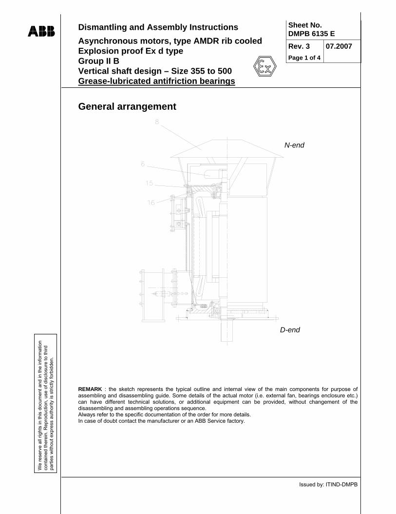
Dismantling and Assembly Instructions Asynchronous motors, type AMDR rib cooled Explosion proof Ex d type Group II B Vertical shaft design – Size 355 to 500 Grease-lubricated antifriction bearings
Issued by: ITIND-DMPB
ABB
Sheet No. DMPB 6135 E Rev. 3 Page 1 of 4
07.2007
We
rese
rve
all r
ight
s in
this
doc
umen
t and
in th
e in
form
atio
n co
ntai
ned
ther
ein.
Rep
rodu
ctio
n, u
se o
f dis
clos
ure
to th
ird
parti
es w
ithou
t exp
ress
aut
horit
y is
stri
ctly
forb
idde
n.
General arrangement
REMARK : the sketch represents the typical outline and internal view of the main components for purpose of assembling and disassembling guide. Some details of the actual motor (i.e. external fan, bearings enclosure etc.) can have different technical solutions, or additional equipment can be provided, without changement of the disassembling and assembling operations sequence. Always refer to the specific documentation of the order for more details. In case of doubt contact the manufacturer or an ABB Service factory.
N-end
D-end

Dismantling and Assembly Instructions Asynchronous motors, type AMDR rib cooled Explosion proof Ex d type Group II B Vertical shaft design – Size 355 to 500 Grease-lubricated antifriction bearings
Issued by: ITIND-DMPB
ABB
Sheet No. DMPB 6135 E Rev. 3 Page 2 of 4
07.2007
We
rese
rve
all r
ight
s in
this
doc
umen
t and
in th
e in
form
atio
n co
ntai
ned
ther
ein.
Rep
rodu
ctio
n, u
se o
f dis
clos
ure
to th
ird
parti
es w
ithou
t exp
ress
aut
horit
y is
stri
ctly
forb
idde
n.
Bearings arrangements

Dismantling and Assembly Instructions Asynchronous motors, type AMDR rib cooled Explosion proof Ex d type Group II B Vertical shaft design – Size 355 to 500 Grease-lubricated antifriction bearings
Issued by: ITIND-DMPB
ABB
Sheet No. DMPB 6135 E Rev. 3 Page 3 of 4
07.2007
We
rese
rve
all r
ight
s in
this
doc
umen
t and
in th
e in
form
atio
n co
ntai
ned
ther
ein.
Rep
rodu
ctio
n, u
se o
f dis
clos
ure
to th
ird
parti
es w
ithou
t exp
ress
aut
horit
y is
stri
ctly
forb
idde
n.
Important! Explosion-proof Ex d motors should be serviced, following the proper instructions, only by trained and certified personnel, preferably under the supervision of ABB Service organisation. Maintenance operations must comply with the rules specified in the EN/IEC 60079-17 and 60079-19 Standards.
Dismantling the Machine
The following sequence of operations refers to the usual maintenance jobs that can be required during overhauls. We suggest to consult the dismantling instruction for horizontal motors (sheet DMPB 6159 E) too, for more details regarding the safety and care to take during some steps.
− Disconnect all cables and leads from power supply, instrumentation, monitoring equipment and earthing.
− Remove any top-mounted accessories or rain protection in order to lift the motor.
− Remove machine holding-down bolts and dowel pins (if any) and uncouple the shaft from the driven machine.
− Lift the machine by lifting lugs. − Fix the rotor by fastening the rotor locking device. − Thoroughly lift the machine and lay it down in
horizontal position on suitable wooden blocks. Terminal boxes should lie on the opposite side.
− Disassemble the fan cowling (08) and remove the external fan (06), slackening the locking screws at the sleeve.
− Remove the rotor locking device. − Pull off the coupling hub from shaft extension (see
sheet DMPB 6173 E). If the machine is provided with a coupling at each end, remove both.
− Remove the snap circlips (10) with the special pliers.
− Pull off the labyrinth seals of bearings (14) and grease valves rings (12) of both sides; these components are fitted with slight interference on the shaft, so it advisable to heat them up to about 80°C using suitable flame before pulling. Remove the screws (4) and the outer bearing covers (13).
Attention! On vertical motors the axially free bearing is located on D side, while the axially fixed bearing, carrying the rotor weight is on N side; consequently, the dismantling instructions shall be carefully applied. − Sustain the rotor on the D side (low) with a cord
tightened around the shaft end and, using a crane or a liftjack, relieve the rotor weight from the bearing. Provide a solid support to release the shaft end on it.
− Remove the bolts (15), which connect the endshield (16) to the stator frame. Secure the endshield to its top centre by using an eyebolt.
− Pull off the endshield from the stator frame by using two suitable bolts inserted into the threaded holes provided in the endshield. The endshield (16) can now be carefully leaned on the shaft. The bearing (1) remains shrunk on the shaft and the flame arresters remain in place.
− Repeat the same steps in order to release the other endshield.
− Protect the exposed parts of the bearings by wrapping them in waxed paper or clean cloth.
− Insert presspan or pressboard protections into the stator bore, between the stator and rotor magnetic cores.
− Using again the crane or the liftjack, lift the rotor sufficiently to remove the solid supports sustaining the shaft ends and lean the rotor on the stator core through the pressboard protections inserted.
− Remove the endshields from the shaft.

Dismantling and Assembly Instructions Asynchronous motors, type AMDR rib cooled Explosion proof Ex d type Group II B Vertical shaft design – Size 355 to 500 Grease-lubricated antifriction bearings
Issued by: ITIND-DMPB
ABB
Sheet No. DMPB 6135 E Rev. 3 Page 4 of 4
07.2007
We
rese
rve
all r
ight
s in
this
doc
umen
t and
in th
e in
form
atio
n co
ntai
ned
ther
ein.
Rep
rodu
ctio
n, u
se o
f dis
clos
ure
to th
ird
parti
es w
ithou
t exp
ress
aut
horit
y is
stri
ctly
forb
idde
n.
− Fit a pressboard protection wrapped around the D-end shaft extension. Slip over the protection a steel tube of proper diameter to have a shaft extension and with this withdraw the rotor from the stator bore travelling from the D-end towards the N-end. Rotor withdrawal requires a free space approximately equal to the machine length.
− Important: during the a.m. operations pay attention to avoid any shock that can damage the stator core surface, the winding and the flame arresters.
The flame arresters surfaces must be free of burrs or signs of any contacts with the shaft during the rotation. If the flame arresters should be removed from the shaft, check the roundness of their surfaces before reassembling. Remark: the instructions relevant removal and reassembling of bearings from the shaft must be followed using particular care. See the instructions for dismantling horizontal motors for more details (sheet DMPB 6159 E). Reassembling the Machine
When reassembling the machine, pay attention to the position of the bearings. The N-side bearing normally carries the axial load and in this case, an angular contact ball bearing is required. The bearings position shall be according to the drawings on page 2. The motor should be reassembled in the reverse order according to the same steps as described for dismantling. Ensure that all screws inside the motor are tight and provided with their original locking devices. Attention! To avoid probably shock damages to the bearings, do not forget to fix the rotor by fastening the rotor locking device before lifting the motor from horizontal to vertical position.

ABB Manual no. DMPB 9016 E Issued by DMPB rev.:3 / July 2007
ABB SACE S.p.A. Head Office and Sales Techinical Dept. and Workshop Via L. Lama, 33 Viale dell’Industria, 18 20099 SESTO S. GIOVANNI 20010 VITTUONE Milan - Italy Milan - Italy Telephone +39 02 2414.1 Tel. +39 02 9034.1 Telefax +39 02 2414.3086 Fax. +39 02 9034.7272 www.abb.com/motors&drives