Optimal Design of 3-phase Squirrel Cage Induction Motors ...
7/1Siemens M 11 · 2003/2004
7
Squirrel-cage motorsDimensions
Notes on the dimensions■ Dimension drawings according to DIN EN 50 347 and
IEC 60 072.
■ FitsThe shaft extensions specified in the dimension ta-bles (DIN 748) and centering spigot diameters (DIN 42 948) are machined with the following fits:
Dimension ISO fitdesignation DIN ISO 286-2
D, DA to 30 j6over 30 to 50 k6over 50 m6
N to 250 j6over 250 h6
F, FA h9
The drilled holes of couplings and belt pulleys should have an ISO fit of at least H7.
■ Dimensional tolerancesFor the following dimensions, the permissible devia-tions are given below:
Dimension Dimension Permitteddesignation deviation
A, B to 250 ± 0.75over 250 to 500 ± 1.0over 500 to 750 ± 1.5over 750 to 1000 ± 2.0over 1000 ± 2.5
M to 200 ± 0.25over 200 to 500 ± 0.5over 500 ± 1.0
H to 250 – 0.5over 250 – 1.0
E, EA – 0.5
Keyways and featherkeys (dimensions GA, GC, F and FA) are made in compli-ance with DIN 6885 Part 1.
■ All dimension data is specified in mm.
7/2
7/47/67/87/107/127/147/167/18
7/20
1LA7, 1MA7 · Frame sizes 56 M to 160 L 1LA5 · Frame sizes 180 M to 225 M1LA9 · Frame sizes 56 to 200 L1LA6, 1MA6 · Frame sizes 100 L to 160 L1MA6 · Frame sizes 180 M to 315 L1LG4 · Frame sizes 180 M to 315 L1LG6 · Frame sizes 180 M to 315 L1LA8 · Frame sizes 315 to 4501MJ6, 1MJ7 · Frame sizes 71 M to 160 L1MJ6 · Frame sizes 180 M to 315 M1MJ8 · Frame sizes 315 M to 355Flange dimensionsDimensions for smoke extraction motors and 1MJ1 motors on request
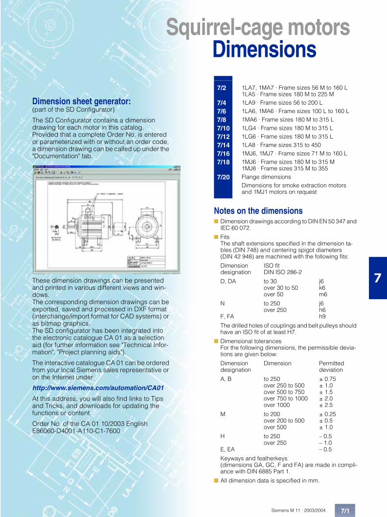
Dimension sheet generator:(part of the SD Configurator)
The SD Configurator contains a dimension drawing for each motor in this catalog. Provided that a complete Order No. is entered or parameterized with or without an order code, a dimension drawing can be called up under the "Documentation" tab.
These dimension drawings can be presented and printed in various different views and win-dows. The corresponding dimension drawings can be exported, saved and processed in DXF format (interchange/import format for CAD systems) or as bitmap graphics. The SD configurator has been integrated into the electronic catalogue CA 01 as a selection aid (for further information see "Technical Infor-mation", "Project planning aids").
The interactive catalogue CA 01 can be ordered from your local Siemens sales representative or on the Internet under
http://www.siemens.com/automation/CA01
At this address, you will also find links to Tips and Tricks, and downloads for updating the functions or content.
Order No. of the CA 01 10/2003 English E86060-D4001-A110-C1-7600

Siemens M 11 · 2003/20047/2
Squirrel-cage motorsDimensions1LA7, 1MA7 · Frame sizes 56 M to 160 L 1LA5 · Frame sizes 180 M to 225 M
7
Squirrel-cage motors
■ IM B 3
■ IM B 5 and IM V1 · For flange dimensions, see Page 7/20 (Z = Number of fixing holes)
For motor Dimension drawing according to IECSize Type
1LA7 . . .1MA7 . . .
No. of poles
A AA AB AC1) AD AD’ AF AF’ AG AQ AS B B’ BA BA’ BB BC BE BE’ C CA CA’
56 M 1LA7 050 V1LA7 053 V
2 to 4 90 25 110 116 101 101 78 78 74 – 37 71 – 28 – 87 34 32 18 36 53 –
63 M . . . . 060. . . . 063
2 to 6 100 27 120 124 101(135)
101 78(95)
78 74(120)
124 37(60)
80 – 28 – 96 30(52.5)
32 18(16)
40 66 –
71 M . . . . 070. . . . 073
2 to 8 112 27 132 145 111(145)
111 88(105)
88 74(120)
124 37(60)
90 – 27 – 106 18(41.5)
32 18(16)
45 83 –
80 M . . . . 080. . . . 083
2 to 8 125 30.5 150 163 120(154)
120(154)
97(114)
97(114)
75(120)
124 37.5(60)
100 – 32 – 118 14(36)
32 18(16)
50 941344)
–
90 S 90 L
. . . . 090
. . . . 0962 to 8 140 30.5 165 180 128
(162)128(162)
105(122)
105(122)
75(120)
170 37.5(60)
100*100
125125*
33 54 143 23(46)
32 18(16)
56 143 118
100 L . . . . 106. . . . 107
2 to 84 and 8
160 42 196 203 135 163 78 123 120 170 60 140 – 47 – 176 39 42 21 63 125 –
112 M . . . . 113 2 to 8 190 46 226 227 148 176 91 136 120 170 60 140 – 47 – 176 32 42 21 70 141 –132 S . . . . 130
. . . . 1312 to 82
216 53 256 267 167 194 107 154 140 250 70 140 – 49 – 180 39 42 21 89 162.5 –
132 M . . . . 133. . . . 134
4 to 86
216 53 256 267 167 194 107 154 140 250 70 178 – 49 – 218 39 42 21 89 124.5162.55)
–
160 M . . . . 163. . . . 164
2 to 82 and 8
254 60 300 320 197 226 127 183 165 250 82.5 210 – 57 – 256 52.5 54 27 108 183 –
160 L . . . . 166 2 to 8 254 60 300 320 197 226 127 183 165 250 82.5 254 – 57 – 300 52.5 54 27 108 1391796)
–
180 M 1LA5 183 2 and 4 279 69.5 339 363 258 258 216 216 152 340 71 241 – 50 – 287 38 54 27 121 259 –180 L 1LA5 186 4 to 8 279 69.5 339 363 258 258 216 216 152 340 71 279 – 50 – 325 38 54 27 121 221 –200 L 1LA5 206 2 and 6 318 83 388 402 305 305 252 252 260 340 96 305 – 58.5 – 355 45 85 42.5 133 239 –
1LA5 207 2 to 8 –225 S 1LA5 220 4 and 8 356 103 426 402 305 305 252 252 260 340 96 286* 311 58 83 361 36 85 42.5 149 248.5225 M 1LA5 223 2
4 to 8356 103 426 402 305 305 252 252 260 340 96 286 311* 58 83 361 36 85 42.5 149 223.5
� �� �
- . � / .�
� �� 0
��
�/ �1
�������&2 3
2
1
1 0
4 3
0 4 .
0 40 3
-
0 3 �
0 �
0 0
�3
1�
4 �
�5
2 �
0
0 �
0 0
0 .
0 � .
4 0 4 3 � 3
/�
/
� �
2 2
1 3
�
� 1 .
64 1 4 4
3 �
3 � .
4 � � 7 � � � # � � % � 8# + � � � � � � 2
/ % � 8 � � # + � # � � � � � * 2� " � � � � � � � * � � � � 9 �� � ! # " , � � � � � � � � & �: � � � � � � % � � � � � � � � � #� � � ) 1 4
� �
��������2 3
2
1
1 0
4
0 4 .
0 4
�3
1�
4 �
� 3
/� �
/ �1
�5
2 �
/
� �
� �
2 2
4 3
4 0
1 3
6� �
4 44 1
4 � � 7 � � � # � � % � 8# + � � � � � � 2
■ The dimensions in brackets apply to 1MA7.
■ For 1LA in pole-changing version (6 or 9 terminals), the dimensions of the basic ver-sion apply.
* This dimension is assigned in DIN EN 50347 to the frame size listed.
V The motors of frame size 56 M are non-ventilated.
1) Measured across the screw heads.
2) With a cast-on terminal housing, 4 knockout openings are provid-ed for metric threads.

1LA7, 1MA7 · Frame sizes 56 M to 160 L1LA5 · Frame sizes 180 M to 225 M
Siemens M 11 · 2003/2004
Squirrel-cage motorsDimensions
7/3
7
■ IM B 35 · For flange dimensions, see Page 7/20 (Z = Number of fixing holes)
■ IM B 14 · For flange dimensions, see Page 7/20 (Z = Number of fixing holes)
� �� �
- . � / .
�
� �� 0
��
�/ �1
��������2 3
2
1
1 0
4
�
3
2 2
0 4
0 3
-
0 3 �
0 �
0 0
�3
1�
4 �
� 3
/�
/
� �
0
0 �0 0
0 .
0 � .
0 4 .
4 3
4 0
1 3
�
� 1 .
6
4 1 4 4
3 �
3 � .
�5
2 � 4 � � 7 � � � # � � % � 8# + � � � � � � 2
/ % � 8 � � # + � # � � � � � * 2� " � � � � � � � * � � � � 9 �� � ! # " , � � � � � � � � & �: � � � � � � % � � � � � � � � � #� � � ) 1 4
� �
�������&2 3
2
1 0
4
0 4 .
0 4
�3
1�
4 �
� 3
/�
�/ �1
�5
2 �
/
� �
� �
2 2
4 3
4 0
1 3
4 44 1
� �6
4 � � 7 � � � # � � % � 8# + � � � � � � 2
Drive-end shaft extension Non-drive-end shaft extensionH HA HH K K’ L LC LL LM O D DB E EB ED F GA DA DC EA EC EE FA GC
56 6 69.5 5.8 9 169 200 74 – 1x M16 x 1.5 1x M25 x 1.5
9 M3 20 14 3 3 10.2 9 M3 20 14 3 3 10.2
63 7 69.5(92.5)
7 10 202.5 232 74(120)
231.5 1x M16 x 1.5 1x M25 x 1.5
11 M4 23 16 3.5 4 12.5 11 M4 23 16 3.5 4 12.5
71 7 63.5(86.5)
7 10 240 278 74(120)
268 1x M16 x 1.5 1x M25 x 1.5
14 M5 30 22 4 5 16 14 M5 30 22 4 5 16
80 8 63.5(86)
9.5 13.5 273.5308.54)
324364
75(120)
299.5334.54)
1x M16 x 1.5 1x M25 x 1.5
19 M6 40 32 4 6 21.5 19 M6 40 32 4 6 21.5
90 10 79(101.5)
10 14 331 389 75(120)
382.5 1x M16 x 1.5 1x M25 x 1.5
24 M8 50 40 5 8 27 19 M6 40 32 4 6 21.5
100 12 102 12 16 372 438 120 423.5 2x M32 x 1.52) 28 M10 60 50 5 8 31 24 M8 50 40 5 8 27
112 12 102 12 16 393 461 120 444.5 2x M32 x 1.52) 28 M10 60 50 5 8 31 24 M8 50 40 5 8 27132 15 128 12 16 452.53) 551.5 140 5053) 2x M32 x 1.52) 38 M12 80 70 5 10 41 38 M12 80 70 5 10 41
132 15 128 12 16 452.53)490.55)
551.5589.55)
140 5053)5435)
2x M32 x 1.52) 38 M12 80 70 5 10 41 38 M12 80 70 5 10 41
160 18 160.5 15 19 588 721 165 640.5 2x M32 x 1.52) 42 M16 110 90 10 12 45 42 M16 110 90 10 12 45
160 18 160.5 15 19 5886286)
7217616)
165 640.5680.56)
2x M32 x 1.52) 42 M16 110 90 10 12 45 42 M16 110 90 10 12 45
180 18 159 15 19 712 841 132 793.5 2 x M40 x 1.5 48 M16 110 100 5 14 51.5 48 M16 110 100 5 14 51.5180 18 159 15 19 712 841 132 793.5 2 x M40 x 1.5 48 M16 110 100 5 14 51.5 48 M16 110 100 5 14 51.5200 24 178 19 25 768.5 897 192 850 2 x M50 x 1.5 55 M20 110 100 5 16 59 55 M20 110 100 5 16 59
225 24 184.5 19 25 806 933.5 192 887.5 2 x M50 x 1.5 60 M20 140 125 7.5 18 64 55 M20 110 100 5 16 59225 24 184.5 19 25 776
806903.5933.5
192 857.5887.5
2 x M50 x 1.5 5560
M20M20
110140
100125
57.5
1618
5964
55 M20 110 100 5 16 59
3) In a low-noise version, the dimen-sion L is 8 mm greater and the di-mension LM is 11.5 mm greater.
4) For 1MA7 083-6.
5) For 1MA7 133-4.
6) For 1MA7 166-4 and 1MA7 166-6.
Siemens M 11 · 2003/20047/4
Squirrel-cage motorsDimensions
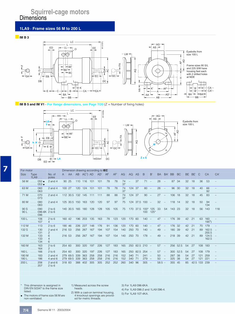
1LA9 · Frame sizes 56 M to 200 L
7
■ IM B 3
■ IM B 5 and IM V1 · For flange dimensions, see Page 7/20 (Z = Number of fixing holes)
For motor Dimension drawing according to IECSize Type
1LA9 . . .No. of poles
A AA AB AC1) AD AD’ AF AF’ AG AQ AS B B’ BA BA’ BB BC BE BE’ C CA CA’
56 M . . . . 050 V. . . . 053 V
2 and 4 90 25 110 116 101 101 78 78 74 37
– 37 71 – 28 – 87 34 32 18 36 53 –
63 M . . . . 060. . . . 063
2 and 4 100 27 120 124 101 101 78 78 74 37
124 37 80 – 28 – 96 30 32 18 40 6692
–
71 M . . . . 070. . . . 073
2 and 4 112 30.5 132 145 111 111 88 88 74 37
124 37 90 – 27 – 106 18 32 18 45 83 –
80 M . . . . 080. . . . 083
2 and 4 125 30.5 150 163 120 120 97 97 75 124 37.5 100 – 32 – 118 14 32 18 50 94134
–
90 S 90 L
. . . . 090
. . . . 096-6K
. . . . 096
2 to 62 to 6
140 30.5 165 180 128 128 105 105 75 170 37.5 100*100
125125*
33 54 143 23 32 18 56 143 118
100 L . . . . 106. . . . 107
2 to 64
160 42 196 203 135 163 78 123 120 170 60 140 – 47 – 176 39 42 21 63 1601955)
–
112 M . . . . 113 2 to 6 190 46 226 227 148 176 91 136 120 170 60 140 – 47 – 176 32 42 21 70 179 –132 S . . . . 130
. . . . 1312 and 42
216 53 256 267 167 194 107 154 140 250 70 140 – 49 – 180 39 42 21 89 162.5200.5
–
132 M . . . . 133. . . . 133. . . . 134
646
216 53 256 267 167 194 107 154 140 250 70 178 – 49 – 218 39 42 21 89 124.5162.5
–
160 M . . . . 163. . . . 164
2 to 62
254 60 300 320 197 226 127 183 165 250 82.5 210 – 57 – 256 52.5 54 27 108 183 –
160 L . . . . 166 2 to 6 254 60 300 320 197 226 127 183 165 250 82.5 254 – 57 – 300 52.5 54 27 108 179 –180 M . . . . 183 2 and 4 279 69.5 339 363 258 258 216 216 152 340 71 241 – 50 – 287 38 54 27 121 259 –180 L . . . . 186 4 and 6 279 69.5 339 363 258 258 216 216 152 340 71 279 – 50 – 325 38 54 27 121 221 –200 L . . . . 206 2 and 6 318 83 388 402 305 305 252 252 260 340 96 305 – 58.5 – 355 45 85 42.5 133 239 –
. . . . 207 2 to 6
� �� �
- . � / .�
� �� 0
��
�/ �1
�������&2 3
2
1
1 0
4 3
0 4 .
0 40 3
-
0 3 �
0 �
0 0
�3
1�
4 �
�5
2 �
0
0 �
0 0
0 .
0 � .
4 0 4 3 � 3
/�
/
� �
2 2
1 3
�
� 1 .
64 1 4 4
3 �
3 � .
4 � � 7 � � � # � � % � 8# + � � � � � � 2
/ % � 8 � � # + � # � � � � � * 2� " � � � � � � � * � � � � 9 �� � ! # " , � � � � � � � � & �: � � � � � � % � � � � � � � � � #� � � ) 1 4
� �
�������2 3
2
1
1 0
4
0 4 .
0 4
�3
1�
4 �
� 3
/� �
/ �1
�5
2 �
/
� �
� �
2 2
4 3
4 0
1 3
6� �
4 4
4 1
4 � � 7 � � � # � � % � 8# + � � � � � � 2
* This dimension is assigned in DIN EN 50347 to the frame size listed.
V The motors of frame size 56 M are non-ventilated.
1) Measured across the screw heads.
2) With a cast-on terminal housing, 4 knockout openings are provid-ed for metric threads.
3) For 1LA9 096-6KA.
4) For 1LA9 096-2 and 1LA9 096-4.
5) For 1LA9 107-4KA.

1LA9 · Frame sizes 56 M to 200 L
Siemens M 11 · 2003/2004
Squirrel-cage motorsDimensions
7/5
7
■ IM B 35 · For flange dimensions, see Page 7/20 (Z = Number of fixing holes)
■ IM B 14 · For flange dimensions, see Page 7/20 (Z = Number of fixing holes)
� �� �
- . � / .
�
� �� 0
��
�/ �1
�������2 3
2
1
1 0
4
�
3
2 2
0 4
0 3
-
0 3 �
0 �
0 0
�3
1�
4 �
� 3
/�
/
� �
0
0 �0 0
0 .
0 � .
0 4 .
4 3
4 0
1 3
�
� 1 .
6
4 1 4 4
3 �
3 � .
�5
2 �4 � � 7 � � � # � � % � 8# + � � � � � � 2
/ % � 8 � � # + � # � � � � � * 2� " � � � � � � � * � � � � 9 �� � ! # " , � � � � � � � � & �: � � � � � � % � � � � � � � � � #� � � ) 1 4
� �
�������&2 3
2
1 0
4
0 4 .
0 4
�3
1�
4 �
� 3
/�
�/ �1
�5
2 �
/
� �
� �
2 2
4 3
4 0
1 3
4 44 1
� �6
4 � � 7 � � � # � � % � 8# + � � � � � � 2
Drive-end shaft extension Non-drive-end shaft extensionH HA HH K K’ L LC LL LM O D DB E EB ED F GA DA DC EA EC EE FA GC
56 6 69.5 5.8 9 169 200 74 – 1x M16 x 1.5 1x M25 x 1.5
9 M3 20 14 3 3 10.2 9 M3 20 14 3 3 10.2
63 7 69.5 7 10 202.5228.5
232258
74 231.5257.5
1x M16 x 1.5 1x M25 x 1.5
11 M4 23 16 3.5 4 12.5 11 M4 23 16 3.5 4 12.5
71 7 63.5 7 10 240 278 74 268 1x M16 x 1.5 1x M25 x 1.5
14 M5 30 22 4 5 16 14 M5 30 22 4 5 16
80 8 63.5 9.5 13.5 273.5308.5
324364
75 299.5334.5
1x M16 x 1.5 1x M25 x 1.5
19 M6 40 32 4 6 21.5 19 M6 40 32 4 6 21.5
90 10 79 10 14 3313763)3584)
3894343)4144)
75 382.5427.53)409.54)
1x M16 x 1.5 1x M25 x 1.5
24 M8 50 40 5 8 27 19 M6 40 32 4 6 21.5
100 12 102 12 16 4074425)
4735085)
120 458.54935)
2x M32 x 1.52) 28 M10 60 50 5 8 31 24 M8 50 40 5 8 27
112 12 102 12 16 431 499 120 482.5 2x M32 x 1.52) 28 M10 60 50 5 8 31 24 M8 50 40 5 8 27132 15 128 12 16 452.5
490.5551.5589.5
140 505543
2x M32 x 1.52) 38 M12 80 70 5 10 41 38 M12 80 70 5 10 41
132 15 128 12 16 452.5490.5
551.5589.5
140 505543
2x M32 x 1.52) 38 M12 80 70 5 10 41 38 M12 80 70 5 10 41
160 18 160.5 15 19 588 721 165 640.5 2x M40 x 1.52) 42 M16 110 90 10 12 45 42 M16 110 90 10 12 45
160 18 160.5 15 19 628 761 165 680.5 2x M40 x 1.52) 42 M16 110 90 10 12 45 42 M16 110 90 10 12 45180 18 159 15 19 712 841 132 793.5 2 x M40 x 1.5 48 M16 110 100 5 14 51.5 48 M16 110 100 5 14 51.5180 18 159 15 19 712 841 132 793.5 2 x M40 x 1.5 48 M16 110 100 5 14 51.5 48 M16 110 100 5 14 51.5200 24 178 19 25 768.5 897 192 850 2 x M50 x 1.5 55 M20 110 100 5 16 59 55 M20 110 100 5 16 59

Siemens M 11 · 2003/20047/6
Squirrel-cage motorsDimensions
1LA6, 1MA6 · Frame sizes 100 L to 160 L
7
■ IM B 3
■ IM B 5 and IM V1 · For flange dimensions, see Page 7/20 (Z = Number of fixing holes)
For motor Dimension drawing according to IECSize Type
1LA6 . . .1MA6 . . .
No. of poles
A AA AB AC1) AD AD’ AF AF’ AG AQ AS B BA BB BC BE BE’ C CA H HA
100 L . . . . 106. . . . 107
2 to 84 and 8
160 40 196 201 164 164 124 124 121 170 60.5 140 46 180 42 42 21 63 125 100 12
112 M . . . . 113 2 to 8 190 42.5 226 225.5 178 178 138 138 121 170 60.5 140 46 180 34 42 21 70 141 112 15132 S . . . . 130
. . . . 1312 to 82
216 50 256 265 194 194 154 154 141 250 70.5 140 47 180 42 42 21 89 162.5 132 17
132 M . . . . 133. . . . 134
4 to 86
216 50 256 265 194 194 154 154 141 250 70.5 178 49 218 42 42 21 89 124.5 132 17
160 M . . . . 163. . . . 164
2 to 82 and 8
254 60 300 320 226 226 183 183 166 250 83 210 63 256 52 54 27 108 183 160 18
160 L . . . . 166 2 to 8 254 60 300 320 226 226 183 183 166 250 83 254 63 300 52 54 27 108 139 160 18
� �� �
- . � / .�
� �� 0
��
�/ �1
��������2 3
2
1
1 0
4 3
0 4 .
0 40 3
-
0 3 �
0 �
0 0
�3
1�
4 �
�5
2 �
4 0 4 3 � 3
/�
/
� �
2 2
1 3
�
� 1 .
64 1 4 4
� �
��������2 3
2
1
1 0
4
0 4 .
0 4
�3
1�
4 �
� 3
/� �
/ �1
�5
2 �
/
� �
� �
2 2
4 3
4 0
1 3
6� �
4 4
4 1
� / .� 1 .
1) Measured across the screw heads.

1LA6, 1MA6 · Frame sizes 100 L to 160 L
Siemens M 11 · 2003/2004
Squirrel-cage motorsDimensions
7/7
7
■ IM B 35 · For flange dimensions, see Page 7/20 (Z = Number of fixing holes)
■ IM B 14 · For flange dimensions, see Page 7/20 (Z = Number of fixing holes)
� �� �
- . � / .
�
� �� 0
��
�/ �1
�������2 3
2
1
1 0
4
�
3
2 2
0 4
0 3
-
0 3 �
0 �
0 0
�3
1�
4 �
� 3
/�
/
� �
0 4 .
4 3
4 0
1 3
�
� 1 .
6
4 1 4 4
�5
2 �
� �
�������2 3
2
1 0
4
0 4 .
0 4
�3
1�
4 �
� 3
/�
�/ �1
�5
2 �
/
� �
� �
2 2
4 3
4 0
1 3
4 44 1
� �6
Drive-end shaft extension Non-drive-end shaft extensionHH K K’ L LC LL LM O D DB E EB ED F GA DA DC EA EC EE FA GC
104.5 12 16 372 438 121 423.5 2x M32 x 1.5 28 M10 60 50 5 8 31 24 M8 50 40 5 8 27
104.5 12 16 393 461 121 444.5 2x M32 x 1.5 28 M10 60 50 5 8 31 24 M8 50 40 5 8 27130.5 12 16 453.5 551.5 141 506 2x M32 x 1.5 38 M12 80 70 5 10 41 38 M12 80 70 5 10 41
130.5 12 16 453.5 551.5 141 506 2x M32 x 1.5 38 M12 80 70 5 10 41 38 M12 80 70 5 10 41
160 14.5 18 588 721 166 640.5 2 x M40 x 1.5 42 M16 110 90 10 12 45 42 M16 110 90 10 12 45
160 14.5 18 588 721 166 640.5 2 x M40 x 1.5 42 M16 110 90 10 12 45 42 M 16 110 90 10 12 45

Siemens M 11 · 2003/20047/8
Squirrel-cage motorsDimensions
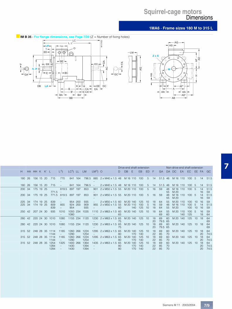
1MA6 · Frame sizes 180 M to 315 L
7
■ IM B 3
■ IM B 5 and IM V1 · For flange dimensions, see Page 7/20 (Z = Number of fixing holes)
For motor Dimension drawing according to IECSize Type
1MA6 . . .No. of poles
A AA AB AC1) AD AD’ AF AF’ AG AH AQ AS B B’ BA BA’ BB BC BE C CA CA’
180 M . . . . 183 24
279 65 344 375 274 274 227 227 220 470 340 82 241* 279 70 108 319 35 75 121 259 –
180 L . . . . 186 4 to 8 279 65 344 375 274 274 227 227 220 470 340 82 241 279* 70 108 319 35 75 121 – 221200 L . . . . 206 2
6318 80 398 402 308 308 248 248 262 530 340 99 305 – 85 85 355 42 85 133 239 –
. . . . 207 2 4 to 8
318 80 398 402 308 308 248 248 262 530 340 99 305 – 85 85 355 42 85 133 239 –
225 S225 M
. . . . 220
. . . . 2234 and 82 4 to 8
356356
8080
436436
442442
339339
339339
269269
269269
264264
580580
425425
100100
286*286
311311*
8585
110110
361361
2525
8585
149149
269–
–244
250 M . . . . 253 2 4 to 8
406 100 506 505 427 427 333 333 338 645 470 120 349 – 100 100 409 39 95 168 283 –
280 S . . . . 280 2 4 to 8
457 100 557 555 452 452 358 358 338 700 525 120 368* 419 100 151 471 30 95 190 317 –
280 M . . . . 283 2 4 to 8
457 100 557 555 452 452 358 358 338 700 525 120 368 419* 100 151 471 30 95 190 – 266
315 S . . . . 310 2 4 to 8
508 120 628 620 515 515 395 395 405 805 590 134 406* 457 125 171 527 32 90 216 358 –
315 M . . . . 313 2 4 to 8
508 120 628 620 515 515 395 395 405 805 590 134 406 457* 125 171 527 32 90 216 – 307
315 L . . . . 316. . . . 317. . . . 318
24 to 86 and 8
508 120 628 620 515 515 395 395 405 805 590 134 508 – 120 120 578 32 90 216 396 –
������72 3
2 ; � 2 .
1
1 04
2 2
0 4
�3
1�
4 �
� 3
/� �/ �1
�5
0
0 �
0 0
0 .
0 � .
3
0 3
-
3 � .
3 �1 3
� �
- . � / .
�
� �
� 0
��
�
� �
2 � ;2 � .
/
� �
4 04 3
64 44 1
� �
� 1 .
Frame sizes 180 M/L, 225 S/M, 280 S/M and 315 S/M have housing feet each with 2 drilled holes at NDE.
� �
������&
2 ; � 2 .
/
� �
1
1 0
4
2 2
0 4
1�
4 �
� 3
/�
�/ �1
1 3
� �
� �
2 3�3
4 0
��
4 3
4 44 1
�5
2 � ;2 � .
6
The motors are supplied with two fitted eyebolts conforming to IM B 5, wherebyone can be repositioned to conform to IM V 1 or IM V 3. Care must be taken to avoid forces perpendicular to the ring.
Type of construction IM B 5 / IM V 1(only up to frame size 315 M)
■ Dimensions for 9-terminal box on request.
* This dimension is assigned in DIN EN 50347 to the frame size listed.
1) Measured across the screw heads.
2) For version with low-noise fan.
3) In the low-noise version, a second shaft end and/or top-mounted sensor is not possible.
1MA6 · Frame sizes 180 M to 315 L
Siemens M 11 · 2003/2004
Squirrel-cage motorsDimensions
7/9
7
■ IM B 35 · For flange dimensions, see Page 7/20 (Z = Number of fixing holes)
������&2 3
2 ; � 2 .
/
� �
1
1 0
4
2 2
0 4
�3
1�
4 �
� 3
/�
�/ �1
0
0 �
0 0
0 .
0 � .
3 0 3
-
3 � .3 �
1 3
� �
� �
- . � / .�
� �
� 0
��
� �
4 0 4 3
�5
2 �
6
�
� 1 .
4 1
4 4
Drive-end shaft extension Non-drive-end shaft extensionH HA HH K K’ L L’2) LC3) LL LM LM’2) O D DB E EB ED F GA DA DC EA EC EE FA GC
180 26 156 15 20 715 770 –
841 164 796.5 885 –
2 x M40 x 1.5 48 M 16 110 100 5 14 51.5 48 M 16 110 100 5 14 51.5
180 26 156 15 20 715 – 841 164 796.5 – 2 x M40 x 1.5 48 M 16 110 100 5 14 51.5 48 M 16 110 100 5 14 51.5200 34 175 19 25
771.5819.5 –
897 197 853 901 –
2 x M50 x 1.5 55 M 20 110 100 5 16 59 4855
M 16M 20
110 100 5 1416
51.559
200 34 175 19 25 771.5 819.5 –
897 197 853 901 –
2 x M50 x 1.5 55 M 20 110 100 5 16 59 4855
M 16M 20
110 100 5 1416
51.559
225225
3434
174174
1919
2525
839 809 839
–855–
954924954
200200
935909935
–955–
2 x M50 x 1.52 x M50 x 1.5
605560
M 20M 20
140110140
125100125
105
10
181618
645964
554855
M 20M 16M 20
110110
100100100
10510
161416
5951.559
250 42 207 24 30 935 1010–
10501080
234 1035 1110–
2 x M63 x 1.5 6065
M 20 140 125 10 18 6469
5560
M 20 110140
100125
5 1618
5964
280 42 220 24 30 1010 1080–
1155 234 1120 1230–
2 x M63 x 1.5 6575
M 20 140 125 10 1820
6979.5
6065
M 20 140 125 10 18 6469
280 42 220 24 30 1010 1080–
1155 234 1120 1230–
2 x M63 x 1.5 6575
M 20 140 125 10 1820
6979.5
6065
M 20 140 125 10 18 6469
315 52 248 28 35 11141144
1185–
12601290
266 12241254
1295–
2 x M63 x 1.5 6580
M 20 140170
125140
10 1822
6985
6070
M 20 140 125 10 1820
6474.5
315 52 248 28 35 11141144
1185–
12601290
266 12241254
1295–
2 x M63 x 1.5 6580
M 20 140170
125140
10 1822
6985
6070
M 20 140 125 10 1820
6474.5
315 52 248 28 35 125412841284
1325––
140014301430
266 136413941394
1435––
2 x M63 x 1.5 658080
M 20 140170170
125140140
10 182222
698585
607070
M 20 140 125 10 182020
6474.574.5

Siemens M 11 · 2003/20047/10
Squirrel-cage motorsDimensions
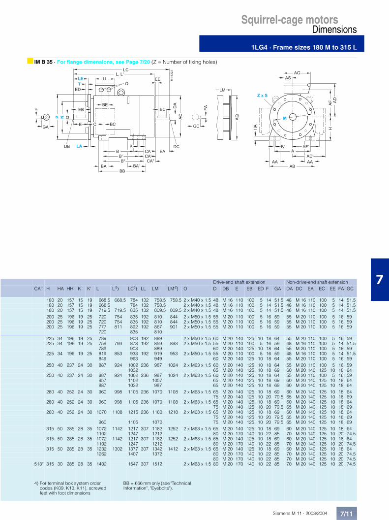
1LG4 · Frame sizes 180 M to 315 L
7
■ IM B 3
■ IM B 5 and IM V1 · For flange dimensions, see Page 7/20 (Z = Number of fixing holes)
For motor Dimension drawing according to IECSize Type
1LG4 . . .No. of poles
A AA AB AC1) AD AD’ AF AF’ AG AH AQ AS B B’ B’’ BA BA’ BB BC BE C CA CA’
180 M . . . . 183 2 and 4 279 65 339 363 262 262 218 218 152 452 340 71 241* 279 – 70 111 328 36 54 121 202* 164180 L . . . . 186 4 to 8 279 65 339 363 262 262 218 218 152 452 340 71 241 279* – 70 111 328 36 54 121 202 164*
. . . . 188 2 to 8 279 65 339 363 262 262 218 218 152 452 340 71 241 279* – 70 111 328 36 54 121 253 215*200 L . . . . 206 2 and 6 318 70 378 402 300 300 247 247 260 486 340 96 305 – – 80 80 355 63 85 133 177 –
. . . . 207 2 to 8 318 70 378 402 300 300 247 247 260 486 340 96 305 – – 80 80 355 63 85 133 177 –
. . . . 208 2 and 6 318 70 378 402 300 300 247 247 260 486 340 96 305 – – 80 80 355 63 85 133 234 –4 and 8 177
225 S . . . . 220 4 and 8 356 80 436 442 325 325 272 272 260 556 425 96 286* 311 – 85 110 361 47 85 149 218* 193225 M . . . . 223 2 356 80 436 442 325 325 272 272 260 556 425 96 286 311* – 85 110 361 47 85 149 218 193*
4 to 8. . . . 228 2 356 80 436 442 325 325 272 272 260 556 425 96 286 311* – 85 110 361 47 85 149 278 253*
4 to 8250 M . . . . 253 2 406 100 490 495 392 392 308 308 300 620 470 117 349 – – 100 100 409 69 110 168 235 –
4 to 8. . . . 258 2 406 100 490 495 392 392 308 308 300 620 470 117 349 – – 100 100 409 69 110 168 235 –
4 3056 and 8 235
280 S . . . . 280 2 457 100 540 555 432 432 348 348 300 672 525 118 368* 419 – 100 151 479 62 110 190 267* 2164 to 8
280 M . . . . 283 2 457 100 540 555 432 432 348 348 300 672 525 118 368 419* – 100 151 479 62 110 190 267 216*4 to 8
. . . . 288 2 457 100 540 555 432 432 348 348 300 672 525 118 368 419* – 100 151 479 62 110 190 377 326*46 and 8 267 216*
315 S . . . . 310 2 508 120 610 610 495 495 406 406 379 780 590 154 406* 457 – 125 176 527 69 110 216 315* 264. . . . 310 4 to 8
315 M . . . . 313 2 508 120 610 610 495 495 406 406 379 780 590 154 406 457* – 125 176 527 69 110 216 315 264*. . . . 313 4 to 8
315 L4) . . . . 316/317 2 508 120 610 610 495 495 406 406 379 780 590 154 457 508* – 125 176 578 69 110 216 424 373*. . . . 316/317 4 to 8. . . . 318 8. . . . 318 6 508 120 610 610 495 495 406 406 379 780 590 154 406 457 508* 155 250 666 69 110 216 615 564
�������72 3
2 ; � 2 .
1
1 04
2 2
0 4
�3
1�
4 �
� 3
/� �
/ �1
�5
0
0 �
0 0
0 .
0 � .
3
0 3
-
3 � .
3 �1 3
� �� �
- . � / .�
� �
� 0
��
� �
2 � ;2 � .
/
� �
4 04 3
�
� 1 .3 � . .0 . .
6 4 44 1
Frame sizes 180 M/L, 225 S/M, 280 S/M and 315 S/M/L have housing feet each with 2 drilled holes at NDE (Exception: 1LG4 318-6 motors have housing feet each with 3 drilled holes at NDE).
� �
������&
2 ; � 2 .
/
� �
1
1 0
4
2 2
0 4
1�
4 �
� 3
/�
�/ �1
1 3
� �
� �
2 3�3
4 0
��
4 3
4 44 1
�5
2 � ;2 � .
6
The motors are supplied with two fitted eyebolts conforming to IM B 5, whereby one can be repositioned to conform to IM V 1 or IM V 3. Care must be taken to avoid forces perpendicular to the ring.
Type of construction IM B 5 / IM V 1(only up to frame size 315 M)
* This dimension is assigned in DIN EN 50347 to the frame size listed.
1) Measured across the screw heads.
2) In version with low-noise fan for 2-pole motors.
3) In the low-noise version, a second shaft end and/or top-mounted sensor is not possible.
1LG4 · Frame sizes 180 M to 315 L
Siemens M 11 · 2003/2004
Squirrel-cage motorsDimensions
7/11
7
■ IM B 35 · For flange dimensions, see Page 7/20 (Z = Number of fixing holes)
Squirrel-cage motors
�������2 3
2 ; � 2 .
/
� �
1
1 0
4
2 2
0 4
�3
1�
4 �
� 3
/�
�/ �1
0
0 �0 0
0 .
0 � .
3 0 3
-
3 � .3 �
1 3
� �
� �
- . � / .�
� �� 0
��
� �
4 0 4 3
�5
2 �
6
�
� 1 .
4 1
4 4
0 . . 3 � . .
Drive-end shaft extension Non-drive-end shaft extensionCA’’ H HA HH K K’ L L’2) LC3) LL LM LM’2) O D DB E EB ED F GA DA DC EA EC EE FA GC
180 20 157 15 19 668.5 668.5 784 132 758.5 758.5 2 x M40 x 1.5 48 M 16 110 100 5 14 51.5 48 M 16 110 100 5 14 51.5180 20 157 15 19 668.5 784 132 758.5 2 x M40 x 1.5 48 M 16 110 100 5 14 51.5 48 M 16 110 100 5 14 51.5180 20 157 15 19 719.5 719.5 835 132 809.5 809.5 2 x M40 x 1.5 48 M 16 110 100 5 14 51.5 48 M 16 110 100 5 14 51.5200 25 196 19 25 720 754 835 192 810 844 2 x M50 x 1.5 55 M 20 110 100 5 16 59 55 M 20 110 100 5 16 59200 25 196 19 25 720 754 835 192 810 844 2 x M50 x 1.5 55 M 20 110 100 5 16 59 55 M 20 110 100 5 16 59200 25 196 19 25 777 811 892 192 867 901 2 x M50 x 1.5 55 M 20 110 100 5 16 59 55 M 20 110 100 5 16 59
720 835 810225 34 196 19 25 789 903 192 889 2 x M50 x 1.5 60 M 20 140 125 10 18 64 55 M 20 110 100 5 16 59225 34 196 19 25 759 793 873 192 859 893 2 x M50 x 1.5 55 M 20 110 100 5 16 59 48 M 16 110 100 5 14 51.5
789 903 889 60 M 20 140 125 10 18 64 55 M 20 110 100 5 16 59225 34 196 19 25 819 853 933 192 919 953 2 x M50 x 1.5 55 M 20 110 100 5 16 59 48 M 16 110 100 5 14 51.5
849 963 949 60 M 20 140 125 10 18 64 55 M 20 110 100 5 16 59250 40 237 24 30 887 924 1002 236 987 1024 2 x M63 x 1.5 60 M 20 140 125 10 18 64 55 M 20 110 100 5 16 59
1032 65 M 20 140 125 10 18 69 60 M 20 140 125 10 18 64250 40 237 24 30 887 924 1002 236 987 1024 2 x M63 x 1.5 60 M 20 140 125 10 18 64 55 M 20 110 100 5 16 59
957 1102 1057 65 M 20 140 125 10 18 69 60 M 20 140 125 10 18 64887 1032 987 65 M 20 140 125 10 18 69 60 M 20 140 125 10 18 64
280 40 252 24 30 960 998 1105 236 1070 1108 2 x M63 x 1.5 65 M 20 140 125 10 18 69 60 M 20 140 125 10 18 6475 M 20 140 125 10 20 79.5 65 M 20 140 125 10 18 69
280 40 252 24 30 960 998 1105 236 1070 1108 2 x M63 x 1.5 65 M 20 140 125 10 18 69 60 M 20 140 125 10 18 6475 M 20 140 125 10 20 79.5 65 M 20 140 125 10 18 69
280 40 252 24 30 1070 1108 1215 236 1180 1218 2 x M63 x 1.5 65 M 20 140 125 10 18 69 60 M 20 140 125 10 18 6475 M 20 140 125 10 20 79.5 65 M 20 140 125 10 18 69
960 1105 1070 75 M 20 140 125 10 20 79.5 65 M 20 140 125 10 18 69315 50 285 28 35 1072 1142 1217 307 1182 1252 2 x M63 x 1.5 65 M 20 140 125 10 18 69 60 M 20 140 125 10 18 64
1102 1247 1212 80 M 20 170 140 10 22 85 70 M 20 140 125 10 20 74.5315 50 285 28 35 1072 1142 1217 307 1182 1252 2 x M63 x 1.5 65 M 20 140 125 10 18 69 60 M 20 140 125 10 18 64
1102 1247 1212 80 M 20 170 140 10 22 85 70 M 20 140 125 10 20 74.5315 50 285 28 35 1232 1302 1377 307 1342 1412 2 x M63 x 1.5 65 M 20 140 125 10 18 69 60 M 20 140 125 10 18 64
1262 1407 1372 80 M 20 170 140 10 22 85 70 M 20 140 125 10 20 74.580 M 20 170 140 10 22 85 70 M 20 140 125 10 20 74.5
513* 315 30 285 28 35 1402 1547 307 1512 2 x M63 x 1.5 80 M 20 170 140 10 22 85 70 M 20 140 125 10 20 74.5
4) For terminal box system order codes (K09, K10, K11), screwed feet with foot dimensions
BB = 666 mm only (see "Technical Information", "Eyebolts").

Siemens M 11 · 2003/20047/12
Squirrel-cage motorsDimensions
1LG6 · Frame sizes 180 M to 315 L
7
■ IM B 3
■ IM B 5 and IM V1 · For flange dimensions, see Page 7/20 (Z = Number of fixing holes)
For motor Dimension drawing according to IECSize Type
1LG6 . . .No. of poles
A AA AB AC1) AD AD’ AF AF’ AG AH AQ AS B B’ B’’ BA BA’ BB BC BE C CA CA’
180 M . . . . 183 2 279 65 339 363 262 262 218 218 152 452 340 71 241* 279 – 70 111 328 36 54 121 253* 2154 202* 164
180 L . . . . 186 4 to 8 279 65 339 363 262 262 218 218 152 452 340 71 241 279* – 70 111 328 36 54 121 253 215*200 L . . . . 206 2 and 6 318 70 378 415 300 300 247 247 260 486 340 96 305 – – 80 80 355 63 85 133 177 –
. . . . 207 2 and 6 318 70 378 415 300 300 247 247 260 486 340 96 305 – – 80 80 355 63 85 133 234 –4 and 8 177
225 S . . . . 220 4 and 8 356 80 436 442 325 325 272 272 260 556 425 96 286* 311 – 85 110 361 47 85 149 218* 193225 M . . . . 223 2 356 80 436 442 325 325 272 272 260 556 425 96 286 311* – 85 110 361 47 85 149 278 253*
4 to 8. . . . 228 2 356 80 436 442 325 325 272 272 260 556 425 96 286 311* – 85 110 361 47 85 149 328 303*
4 to 6250 M . . . . 253 2 406 100 490 495 392 392 308 308 300 620 470 118 349 – – 100 100 409 69 110 168 235 –
4 3056 and 8 235
. . . . 258 2 406 100 490 495 392 392 308 308 300 620 470 118 349 – – 100 100 409 69 110 168 305 –4 to 6
280 S . . . . 280 2 457 100 540 555 432 432 348 348 300 672 525 118 368* 419 – 100 151 479 62 110 190 267* 2164 to 8
280 M . . . . 283 2 457 100 540 555 432 432 348 348 300 672 525 118 368 419* – 100 151 479 62 110 190 377 326*46 and 8 267 216*
. . . . 288 2 457 100 540 555 432 432 348 348 300 672 525 118 368 419* – 100 151 479 62 110 190 377 226*4 to 6
315 S . . . . 310 2 508 120 610 610 495 495 406 406 379 780 590 154 406* 457 – 125 176 527 69 110 216 315* 264. . . . 310 4 to 8
315 M . . . . 313 8 508 120 610 610 495 495 406 406 379 780 590 154 406 457* – 125 176 527 69 110 216 315 264*. . . . 313 2 508 120 610 610 495 495 406 406 379 780 590 154 457* 508 – 125 176 578 69 110 216 424* 373. . . . 313 4 and 6
315 L4) . . . . 316 2 508 120 610 610 495 495 406 406 379 780 590 154 457 508* – 125 176 578 69 110 216 424 373*. . . . 316 4 and 6. . . . 316/317 8. . . . 317/318 2 508 120 610 610 495 495 406 406 379 780 590 154 406 457 508* 155 250 666 69 110 216 615 564. . . . 317/318 4 and 6. . . . 318 8
�������72 3
2 ; � 2 .
1
1 04
2 2
0 4
�3
1�
4 �
� 3
/� �
/ �1
�5
0
0 �
0 0
0 .
0 � .
3
0 3
-
3 � .
3 �1 3
� �� �
- . � / .�
� �
� 0
��
� �
2 � ;2 � .
/
� �
4 04 3
�
� 1 .3 � . .0 . .
6 4 44 1
Frame sizes 180 M/L, 225 S/M, 280 S/M and 315 S/M/L have housing feet each with 2 drilled holes at NDE (Exception: 2-, 4- and 6-pole 1LG6 317 motors and 1LG6 318 motors have hous-ing feet each with 3 drilled holes at NDE).
� �
������&
2 ; � 2 .
/
� �
1
1 0
4
2 2
0 4
1�
4 �
� 3
/�
�/ �1
1 3
� �
� �
2 3�3
4 0
��
4 3
4 44 1
�5
2 � ;2 � .
6
The motors are supplied with two fitted eyebolts conforming to IM B 5, whereby one can be repositioned to conform to IM V 1 or IM V 3. Care must be taken to avoid forces perpendicular to the ring.
Type of construction IM B 5 / IM V 1(only up to frame size 315 M)
Frame size IM V 1
* This dimension is assigned in DIN EN 50347 to the frame size listed.
1) Measured across the screw heads.
2) For version with low-noise fan.
3) In the low-noise version, a second shaft end and/or top-mounted sensor is not possible.

1LG6 · Frame sizes 180 M to 315 L
Siemens M 11 · 2003/2004
Squirrel-cage motorsDimensions
7/13
7
■ IM B 35 · For flange dimensions, see Page 7/20 (Z = Number of fixing holes)
Squirrel-cage motors
�������2 3
2 ; � 2 .
/
� �
1
1 0
4
2 2
0 4
�3
1�
4 �
� 3
/�
�/ �1
0
0 �0 0
0 .
0 � .
3 0 3
-
3 � .3 �
1 3
� �
� �
- . � / .�
� �� 0
��
� �
4 0 4 3
�5
2 �
6
�
� 1 .
4 1
4 4
0 . . 3 � . .
Drive-end shaft extension Non-drive-end shaft extensionCA’’ H HA HH K K’ L L’2) LC3) LL LM LM’2) O D DB E EB ED F GA DA DC EA EC EE FA GC
180 20 157 15 19 719.5 835 132 809.5 2 x M40 x 1.5 48 M 16 110 100 5 14 51.5 48 M 16 110 100 5 14 51.5668.5 784 758.5
180 20 157 15 19 719.5 835 132 809.5 2 x M40 x 1.5 48 M 16 110 100 5 14 51.5 48 M 16 110 100 5 14 51.5200 25 196 19 25 756 835 192 846 2 x M50 x 1.5 55 M 20 110 100 5 16 59 55 M 20 110 100 5 16 59200 25 196 19 25 813 892 192 903 2 x M50 x 1.5 55 M 20 110 100 5 16 59 55 M 20 110 100 5 16 59
756 835 846225 34 196 19 25 789 903 192 889 2 x M50 x 1.5 60 M 20 140 125 10 18 64 55 M 20 110 100 5 16 59225 34 196 19 25 819 933 192 919 2 x M50 x 1.5 55 M 20 110 100 5 16 59 48 M 16 110 100 5 14 51.5
849 963 949 60 M 20 140 125 10 18 64 55 M 20 110 100 5 16 59225 34 196 19 25 869 983 192 969 2 x M50 x 1.5 55 M 20 110 100 5 16 59 48 M 16 110 100 5 14 51.5
900 1013 1000 60 M 20 140 125 10 18 64 55 M 20 110 100 5 16 59250 40 237 24 30 887 1002 236 987 2 x M63 x 1.5 60 M 20 140 125 10 18 64 55 M 20 110 100 5 16 59
957 1102 1057 65 M 20 140 125 10 18 69 60 M 20 140 125 10 18 64887 1032 987 65 M 20 140 125 10 18 69 60 M 20 140 125 10 18 64
250 40 237 24 30 957 1102 236 1057 2 x M63 x 1.5 60 M 20 140 125 10 18 64 55 M 20 110 100 5 16 5965 M 20 140 125 10 18 69 60 M 20 140 125 10 18 64
280 40 252 24 30 960 1105 236 1070 2 x M63 x 1.5 65 M 20 140 125 10 18 69 60 M 20 140 125 10 18 6475 M 20 140 125 10 20 79.5 65 M 20 140 125 10 18 69
280 40 252 24 30 1070 1215 236 1180 2 x M63 x 1.5 65 M 20 140 125 10 18 69 60 M 20 140 125 10 18 6475 M 20 140 125 10 20 79.5 65 M 20 140 125 10 18 69
960 1105 1070 75 M 20 140 125 10 20 79.5 65 M 20 140 125 10 18 69280 40 252 24 30 1070 1215 236 1180 2 x M63 x 1.5 65 M 20 140 125 10 18 69 60 M 20 140 125 10 18 64
75 M 20 140 125 10 20 79.5 65 M 20 140 125 10 18 69315 50 285 28 35 1072 1217 307 1182 2 x M63 x 1.5 65 M 20 140 125 10 18 69 60 M 20 140 125 10 18 64
1102 1247 1212 80 M 20 170 140 10 22 85 70 M 20 140 125 10 20 74.5315 50 285 28 35 1102 1247 307 1212 2 x M63 x 1.5 80 M 20 170 140 10 22 85 70 M 20 140 125 10 20 74.5315 50 285 28 35 1232 1377 307 1342 2 x M63 x 1.5 65 M 20 140 125 10 18 69 60 M 20 140 125 10 18 64
1262 1407 1372 80 M 20 170 140 10 22 85 70 M 20 140 125 10 20 74.5315 50 285 28 35 1232 1377 307 1342 2 x M63 x 1.5 65 M 20 140 125 10 18 69 60 M 20 140 125 10 18 64
1262 1407 1372 80 M 20 170 140 10 22 85 70 M 20 140 125 10 20 74.580 M 20 170 140 10 22 85 70 M 20 140 125 10 20 74.5
513* 315 30 285 28 35 1372 1517 307 1482 2 x M63 x 1.5 65 M 20 140 125 10 18 69 60 M 20 140 125 10 18 641402 1547 1512 80 M 20 170 140 10 22 85 70 M 20 140 125 10 20 74.5
80 M 20 170 140 10 22 85 70 M 20 140 125 10 20 74.5
4) For terminal box system order codes (K09, K10, K11), screwed feet with foot dimensions
BB = 666 mm only (see "Technical Information", "Eyebolts").

Siemens M 11 · 2003/20047/14
Squirrel-cage motorsDimensions
1LA8 · Frame sizes 315 to 450
7
■ IM B 3
■ IM V1 · For flange dimensions, see Page 7/20 (Z = Number of fixing holes)
For motor Dimension drawing according to IECSize Type
1LA8 . . .No. of poles A AA AB AC1) AD AD’ AG AG’ AQ B BA BB BC BE C CA H HA
315 . . . . 315. . . . 317. . . . 31 .
2 4 to 84 to 82)
560 120 680 710 570 582 473 481 670 630 180 780 195 110 180180200
435 315 28
355 . . . . 353. . . . 355. . . . 35 .
2 4 to 84 to 82)
630 150 780 790 710 730 585 600 750 800 220 980 185 135 200200224
470 355 35
400 . . . . 403. . . . 405. . . . 407
2 4 to 8
710 150 860 880 865 930 775 795 850 900 220 1080 186 100 224 506 400 35
450 . . . . 453. . . . 455. . . . 457
23)4 to 8
800 180 980 970 900 980 810 845 950 1000 260 1220 170 100 250 540 450 42
� -
� 1
0 0
1
0
/
� �
3
0 4
2 32
�������
�3
40 �
1 0
-3 � 4 �
1�
1 3
/�
� 3
���
- <
�
� �
� 0
� � �0
�1
0 3
2 2
4 0 4 3
1
/
� �2
1 0
� �
�-
�3
�0.
�1.
��.
2 2
�������6
4 0
40 4
�3
�5
2 �
��������
����� ������ ���������������
��� ���������������
��������
����� ������ ���������������
���������������������
��������
����� ������ ���������������
������������������ ���!�
Basic version Special designs
Terminal box position
1) Measured across the screw heads (not in the flattened area of the fan cowl).
2) With bearing for increased canti-lever forces.
3) Only for 50 Hz.

1LA8 · Frame sizes 315 to 450
Siemens M 11 · 2003/2004
Squirrel-cage motorsDimensions
7/15
7
■ IM B 35 · For flange dimensions, see Page 7/20 (Z = Number of fixing holes)
0 00
/
� �
3
2 32
�������&
�3
0 �
1 0
-3 � 4 �
1�
1 3
/�
� 30 3
2 2
4 3
4 0
4
1
��
�
- .�
� �
� 0
� �
� -
� 1
�0
�1
0 4
Drive-end shaft extension Non-drive-end shaft extensionHB HB’ HD HK K K’ L LC LL LM O D DB E EB F GA DA DC EA EC FA GC
360 290 825 170 26 33 137014001420
149515551575
307 15001530
M 63 x 1.5 65 8595
M 20M 20M 24
140170170
125140140
182225
6990
100
507070
M 16M 20M 20
110140140
100125125
142020
53.574.574.5
400 285 905 229 33 40 159516251690
175018101874
330 17351765
M 72 x 2 75 95
100
20 S24 M24 M
140170210
125140180
202528
79.5 100 106
60 80
80
M 20
M 20
140170170
125140140
182222
64 85
85440 400 1020 320 33 40 1785
182519402010
550 19351975
Ø 80 80110
M 20M 24
170210
140180
2228
85116
7090
M 20M 24
140170
125140
2025
74.595
525 400 1110 320 39 47 19451985
21002210
550 21052145
Ø 80 90120
M 24 170210
140180
2532
95127
75100
M 20M 24
140210
125180
2028
79.5106
������"�
����� ������ ���������������
#$�%�&#$�����������'%��(
��������
����� ������ ���������������
#$�%�&#$������������� ���!�

Siemens M 11 · 2003/20047/16
Squirrel-cage motorsDimensions
1MJ6 · Frame sizes 71 M to 160 L
7
■ IM B 3
■ IM B5 and IM V1 · For flange dimensions, see Page 7/20 (Z = Number of fixing holes)
For motor Dimension drawing according to IECSize Type
1MJ6 . . .No. of poles
A AA AB AC1) AD AF AG AQ AS B BA BB BC BE C CA H HA HH K K’ L
71 M . . . . 070 2 and 4 112 34 140 148.5 2012) 162 152 124 71 90 30 110 58 54 45 144 71 8 103 7 10 299. . . . 073 2 to 6
80 M . . . . 080 2 to 6 125 36 160 165.5 2092) 170 152 125 71 100 35 125 44 54 50 156 80 10 93.5 9.5 13.5 336. . . . 083 2 to 6
90 L . . . . 096 2 to 8 140 37 168 183 218 177 162 170 81 125 35 156 54 54 56 177 90 13 109.5 10 14 383. . . . 097 2 to 8
100 L . . . . 106 2 to 8 160 45 196 202.5 223 182 162 170 81 140 45 176 50 54 63 185 100 14 112.5 12 16 426. . . . 107 4 and 8
112 M . . . . 113 2 to 8 190 50 226 228.5 238 197 162 170 81 140 45 176 52 54 70 180 112 15 121.5 12 16 428132 S . . . . 130 2 to 8 216 53 256 267.5 258 217 162 250 81 140 49 180 55 54 89 228 132 17 144 12 16 515
. . . . 131 2132 M . . . . 133 4 to 8 216 53 256 267.5 258 217 162 250 81 178 49 218 55 54 89 190 132 17 144 12 16 515
. . . . 134 6160 M . . . . 163 2 to 8 254 60 300 323 280 239 162 250 81 210 57 256 40 54 108 238 160 20 148 15 19 641
. . . . 164 2 and 8160 L . . . . 166 2 to 8 254 60 300 323 314 246 216 250 95 254 57 300 40 96 108 194 160 20 148 15 19 641
�������&
� 0
�� �
4 �
1 3
��
- . � 1
�1
�/
�
� �� �
2 �
�5
� 3
/�1�
�3
4 3
3 �0
-
0 00 �
34
4 01 0
� �
1
/
0 3
2 32
2 /2 20 4
6
4 14 4
4 � � 7 � � � # � � % � 8# + � � � � � � 2
1
2 32
2 /2 2
� �0 4
6
4
4 0� �
/
1 0
4 �
4 3
1 3
� 3
1�
�3
/�
�5
2 �
� �� �
�1
�/
4 1
4 4
��������
4 � � 7 � � � # � � % � 8# + � � � � � � 2
1) Measured across the screw heads.
2) K09 and K10 from frame size 90 upwards.

1MJ6 · Frame sizes 71 M to 160 L
Siemens M 11 · 2003/2004
Squirrel-cage motorsDimensions
7/17
7
■ IM B 35 · For flange dimensions, see Page 7/20 (Z = Number of fixing holes)
■ IM B 14 – For 1MJ6 frame sizes 71 M to 90 L · For flange dimensions, see Page 7/20 (Z = Number of fixing holes)
0 0
1
0
/
� �
0 3
2 32
��������
4
3 � 4 �
1�
/�
� 3
��
- .�
� 0
�/
0 4
� �
�1
� �2 2
2 /
�3
0 �
3
-
1 0
�
4 0 4 3
1 3
�5
6
� �
� 1
2 �
4 1
4 4
4 � � 7 � � � # � � % � 8# + � � � � � � 2
1
/
��������
1�
/�
�3
�5
4 04 3
� �
� �
2 32
2 2
0 4
2 �
�/�1
� 3
1 0
4
� �
1 3
4 �
6
4 1
4 4
Drive-end shaft extension Non-drive-end shaft extensionLC LF LL LM O D DB E EB ED F GA DA DC EA EC EE FA GC
339 – 132 327 2 x M25 x 1.5 14 M 5 30 22 4 5 16 14 M 5 30 22 4 5 16
386 – 132 362 2 x M25 x 1.5 19 M 6 40 32 4 6 21.5 19 M 6 40 32 4 6 21.5
458 – 162 434.5 2 x M25 x 1.5 24 M 8 50 40 5 8 27 24 M 8 50 40 5 8 27
508 – 162 477.5 2x M32 x 1.5 28 M 10 60 50 5 8 31 28 M 10 60 50 5 8 31
510 – 162 479.5 2x M32 x 1.5 28 M 10 60 50 5 8 31 28 M 10 60 50 5 8 31617 – 162 567.5 2x M32 x 1.5 38 M 12 80 70 5 10 41 38 M 12 80 70 5 10 41
617 – 162 567.5 2x M32 x 1.5 38 M 12 80 70 5 10 41 38 M 12 80 70 5 10 41
776 383 162 693.5 2 x M40 x 1.5 42 M 16 110 90 10 12 45 42 M 16 110 90 10 12 45
776 383 190 693.5 2 x M40 x 1.5 42 M 16 110 90 10 12 45 42 M 16 110 90 10 12 45
Siemens M 11 · 2003/20047/18
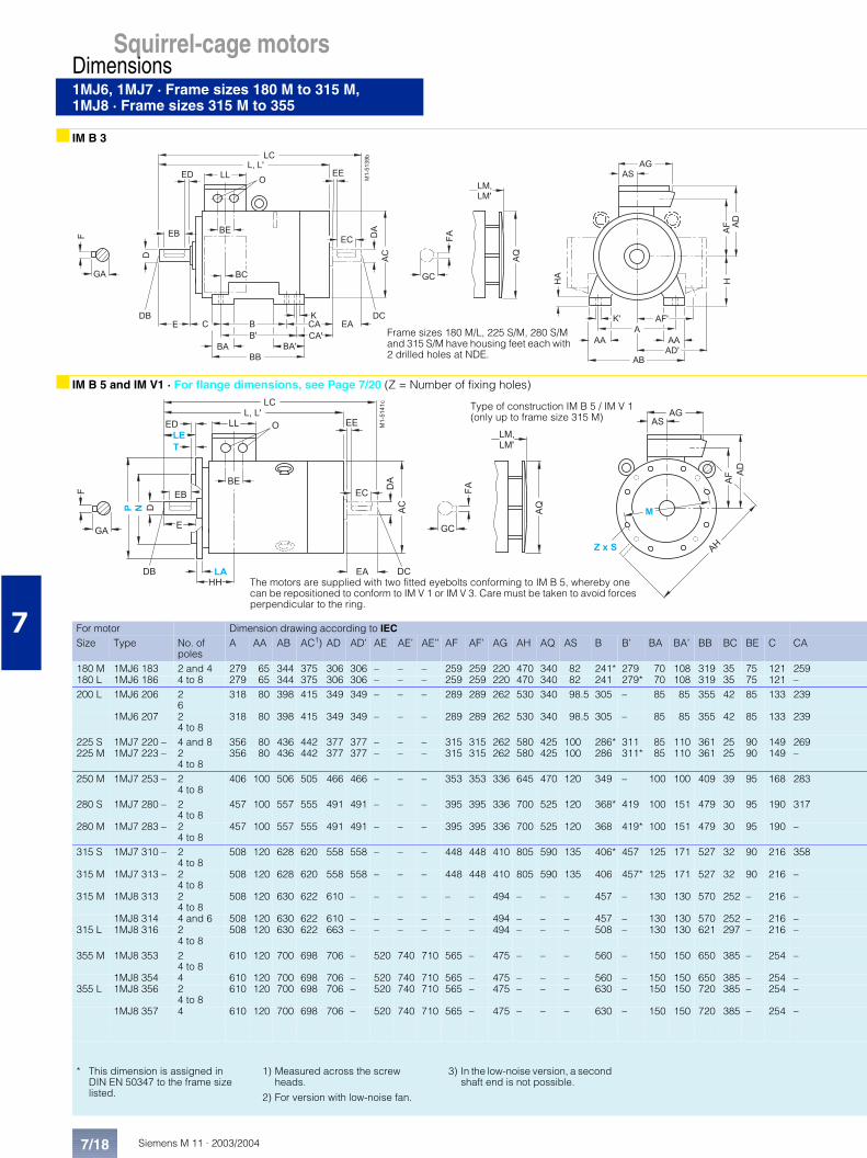
Squirrel-cage motorsDimensions1MJ6, 1MJ7 · Frame sizes 180 M to 315 M,1MJ8 · Frame sizes 315 M to 355
7
■ IM B 3
■ IM B 5 and IM V1 · For flange dimensions, see Page 7/20 (Z = Number of fixing holes)
For motor Dimension drawing according to IECSize Type No. of
polesA AA AB AC1) AD AD’ AE AE’ AE’’ AF AF’ AG AH AQ AS B B’ BA BA’ BB BC BE C CA
180 M 1MJ6 183 2 and 4 279 65 344 375 306 306 – – – 259 259 220 470 340 82 241* 279 70 108 319 35 75 121 259180 L 1MJ6 186 4 to 8 279 65 344 375 306 306 – – – 259 259 220 470 340 82 241 279* 70 108 319 35 75 121 –200 L 1MJ6 206 2
6318 80 398 415 349 349 – – – 289 289 262 530 340 98.5 305 – 85 85 355 42 85 133 239
1MJ6 207 2 4 to 8
318 80 398 415 349 349 – – – 289 289 262 530 340 98.5 305 – 85 85 355 42 85 133 239
225 S 1MJ7 220 – 4 and 8 356 80 436 442 377 377 – – – 315 315 262 580 425 100 286* 311 85 110 361 25 90 149 269225 M 1MJ7 223 – 2
4 to 8356 80 436 442 377 377 – – – 315 315 262 580 425 100 286 311* 85 110 361 25 90 149 –
250 M 1MJ7 253 – 2 4 to 8
406 100 506 505 466 466 – – – 353 353 336 645 470 120 349 – 100 100 409 39 95 168 283
280 S 1MJ7 280 – 2 4 to 8
457 100 557 555 491 491 – – – 395 395 336 700 525 120 368* 419 100 151 479 30 95 190 317
280 M 1MJ7 283 – 2 4 to 8
457 100 557 555 491 491 – – – 395 395 336 700 525 120 368 419* 100 151 479 30 95 190 –
315 S 1MJ7 310 – 2 4 to 8
508 120 628 620 558 558 – – – 448 448 410 805 590 135 406* 457 125 171 527 32 90 216 358
315 M 1MJ7 313 – 2 4 to 8
508 120 628 620 558 558 – – – 448 448 410 805 590 135 406 457* 125 171 527 32 90 216 –
315 M 1MJ8 313 2 4 to 8
508 120 630 622 610 – – – – – – 494 – – – 457 – 130 130 570 252 – 216 –
1MJ8 314 4 and 6 508 120 630 622 610 – – – – – – 494 – – – 457 – 130 130 570 252 – 216 –315 L 1MJ8 316 2 508 120 630 622 663 – – – – – – 494 – – – 508 – 130 130 621 297 – 216 –
4 to 8355 M 1MJ8 353 2
4 to 8610 120 700 698 706 – 520 740 710 565 – 475 – – – 560 – 150 150 650 385 – 254 –
1MJ8 354 4 610 120 700 698 706 – 520 740 710 565 – 475 – – – 560 – 150 150 650 385 – 254 –355 L 1MJ8 356 2
4 to 8610 120 700 698 706 – 520 740 710 565 – 475 – – – 630 – 150 150 720 385 – 254 –
1MJ8 357 4 610 120 700 698 706 – 520 740 710 565 – 475 – – – 630 – 150 150 720 385 – 254 –
������72 3
2 ; � 2 .
1
1 04
2 2
0 4
�3
1�
4 �
� 3
/� �/ �1
�5
0
0 �
0 0
0 .
0 � .
3
0 3
-
3 � .
3 �1 3
� �
- . � / .
�
� �
� 0
��
�
� �
2 � ;2 � .
/
� �
4 04 3
64 44 1
� �
� 1 .
Frame sizes 180 M/L, 225 S/M, 280 S/M and 315 S/M have housing feet each with2 drilled holes at NDE.
� �
������&
2 ; � 2 .
/
� �
1
1 0
4
2 2
0 4
1�
4 �
� 3
/�
�/ �1
1 3
� �
� �
2 3�3
4 0
��
4 3
4 44 1
�5
2 � ;2 � .
6
The motors are supplied with two fitted eyebolts conforming to IM B 5, whereby one can be repositioned to conform to IM V 1 or IM V 3. Care must be taken to avoid forces perpendicular to the ring.
Type of construction IM B 5 / IM V 1(only up to frame size 315 M)
* This dimension is assigned in DIN EN 50347 to the frame size listed.
1) Measured across the screw heads.
2) For version with low-noise fan.
3) In the low-noise version, a second shaft end is not possible.

1MJ6, 1MJ7 · Frame sizes 180 M to 315 M,1MJ8 · Frame sizes 315 M to 355
Siemens M 11 · 2003/2004
Squirrel-cage motorsDimensions
7/19
7
■ IM B 35 · For flange dimensions, see Page 7/20 (Z = Number of fixing holes)
Drive-end shaft extension Non-drive-end shaft extensionCA’ H HH HA K K’ L L’2) LC3) LL LM LM’2) O D DB E EB ED F GA DA DC EA EC EE FA GC
– 180 156 26 15 20 715 770 841 164 796.5 885 2 x M 40 x 1.5 48 M 16 110 100 5 14 51.5 48 M 16 110 100 5 14 51.5221 180 156 26 15 20 715 – 841 164 796.5 – 2 x M 40 x 1.5 48 M 16 110 100 5 14 51.5 48 M 16 110 100 5 14 51.5– 200 175 34 19 25 771.5 825
–897 197 853 910
–2 x M 50 x 1.5 55 M 20 110 100 5 16 59 48
55M 16M 20
110 100 5 1416
51.559
– 200 175 34 19 25 771.5 825–
897 197 853 910–
2 x M 50 x 1.5 55 M 20 110 100 5 16 59 4855
M 16M 20
110 100 5 1416
51.559
– 225 174 34 19 25 839 – 954 197 939 – 2 x M 50 x 1.5 60 M 20 140 125 10 18 64 55 M 20 110 100 5 16 59244 225 174 34 19 25 809
839855–
924954
197 909939
955–
2 x M 50 x 1.5 55 60
M 20 110140
100125
510
1618
5964
4855
M 16M 20
110 100 5 1416
51.559
– 250 207 42 24 30 930 1010–
10501080
234 1035 1110–
2 x M 63 x 1.5 60 65
M 20 140 125 10 18 6469
5560
M 20 110140
100125
510
1618
5964
– 280 220 42 24 30 1010 1080–
1155 234 1120 1230–
2 x M 63 x 1.5 65 75
M 20 140 125 10 1820
6979.5
6065
M 20 140 125 10 18 6469
266 280 220 42 24 30 1010 1080–
1155 234 1120 1230–
2 x M 63 x 1.5 65 75
M 20 140 125 10 1820
6979.5
6065
M 20 140 125 10 18 6469
– 315 248 56 28 35 11141140
1185–
12601290
266 12241250
1295–
2 x M 63 x 1.5 65 80
M 20 140170
125140
10 1822
6985
6070
M 20 140 125 10 1820
6474.5
307 315 248 56 28 35 11141140
1185–
12601290
266 12241250
1295–
2 x M 63 x 1.5 65 80
M 20 140170
125140
10 1822
6985
6070
M 20 140 125 10 1820
6474.5
– 315 468 30 28 28 12411343
– 14401563
– 14041455
– 2 x M 63 x 1.5 65 80
M 20M 20
140170
125140
1822
6985
6580
M 20M 20
140170
125140
1822
6985
– 315 468 30 28 28 1343 – 1563 – 1455 – 2 x M 63 x 1.5 80 M 20 170 140 22 85 80 M 20 170 140 22 85– 315 513 30 28 28 1351 – 1550 – 1514 – 2 x M 63 x 1.5 65 M 20 140 125 18 69 65 M 20 140 125 18 69
1453 1673 1565 80 M 20 170 140 22 85 80 M 20 170 140 22 85– 355 – 30 28 28 1650
168015901640
– – 17501800
– 35 – 75 75 90
M 20M 24
140170
125140
2025
79.595
7590
M 20M 24
140170
125140
2025
79.595
– 355 – 30 28 28 1680 1640 – – 1800 – 35 – 75 90 M 24 170 140 25 95 90 M 24 170 140 25 95– 355 – 30 28 28 1780
181017251775
– – 18841934
– 35 – 75 75 90
M 20M 24
140170
125140
2025
79.595
7590
M 20M 24
140170
125140
2025
79.595
– 355 – 30 28 28 1810 1775 – – 1934 – 35 – 75 90 M 24 170 140 25 95 90 M 24 170 140 25 95
��������
� �
��
��������
� � � �
�� �
�
� �
� �
�
�
��
�
�
��
�� ��
�
� �
� �
�
� �
�
�
�
��
� �
� �
� � � �
� �
� �
��
� �
�
��
� �
�
�
� �
�
�
� � � � � � � � � � � � ! " � � � # # � �
$ ! � % � �
Frame sizes 180 M/L, 225 S/M, 280 S/M and 315 S/M have housing feet each with 2 drilled holes at NDE.
� � � � � � � �
� �
�
Siemens M 11 · 2003/20047/20
Squirrel-cage motorsDimensions
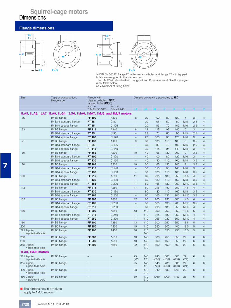
Flange dimensions
7
Size Type of construction,flange type
Flange with clearance holes (FF/A)tapped holes (FT/C)
Dimension drawing according to IEC
acc. to acc. toDIN EN 50 347 DIN 42 948 LA LE M N P S T Z
1LA5, 1LA6, 1LA7, 1LA9, 1LG4, 1LG6, 1MA6, 1MA7, 1MJ6, and 1MJ7 motors56 IM B5 flange FF 100 A120 8 20 100 80 120 7 3 4
IM B14 standard flange FT 65 C 80 – 20 65 50 80 M 5 2.5 4IM B14 special flange FT 85 C 105 – 20 85 70 105 M 6 2.5 4
63 IM B5 flange FF 115 A140 8 23 115 95 140 10 3 4IM B14 standard flange FT 75 C 90 – 23 75 60 90 M 5 2.5 4IM B14 special flange FT 100 C 120 – 23 100 80 120 M 6 3 4
71 IM B5 flange FF 130 A160 9 30 130 110 160 10 3.5 4IM B14 standard flange FT 85 C 105 – 30 85 70 105 M 6 2.5 4IM B14 special flange FT 115 C 140 – 30 115 95 140 M 8 3 4
80 IM B5 flange FF 165 A200 10 40 165 130 200 12 3.5 4IM B14 standard flange FT 100 C 120 – 40 100 80 120 M 6 3 4IM B14 special flange FT 130 C 160 – 40 130 110 160 M 8 3.5 4
90 IM B5 flange FF 165 A200 10 50 165 130 200 12 3.5 4IM B14 standard flange FT 115 C 140 – 50 115 95 140 M 8 3 4IM B14 special flange FT 130 C 160 – 50 130 110 160 M 8 3.5 4
100 IM B5 flange FF 215 A250 11 60 215 180 250 14.5 4 4IM B14 standard flange FT 130 C 160 – 60 130 110 160 M 8 3.5 4IM B14 special flange FT 165 C 200 – 60 165 130 200 M 10 3.5 4
112 IM B5 flange FF 215 A250 11 60 215 180 250 14.5 4 4IM B14 standard flange FT 130 C 160 – 60 130 110 160 M 8 3.5 4IM B14 special flange FT 165 C 200 – 60 165 130 200 M 10 3.5 4
132 IM B5 flange FF 265 A300 12 80 265 230 300 14.5 4 4IM B14 standard flange FT 165 C 200 – 80 165 130 200 M 10 3.5 4IM B14 special flange FT 215 C 250 – 80 215 180 250 M 12 4 4
160 IM B5 flange FF 300 A350 13 110 300 250 350 18.5 5 4IM B14 standard flange FT 215 C 250 – 110 215 180 250 M 12 4 4IM B14 special flange FT 250 C 300 – 110 265 230 300 M 12 4 4
180 IM B5 flange FF 300 A350 13 110 300 250 350 18.5 5 4200 IM B5 flange FF 350 A400 15 110 350 300 400 18.5 5 4225 2-pole
4-pole to 8-poleIM B5 flange FF 400 A450 16 110
140400 350 450 18.5 5 8
250 IM B5 flange FF 500 A550 18 140 500 450 550 22 6 8280 IM B5 flange FF 500 A550 18 140 500 450 550 22 6 8315 2-pole
4-pole to 8-poleIM B5 flange FF 600 A660 22 140
170600 550 660 22 6 8
1LA8, 1MJ8 motors315 2-pole
4-pole to 8-poleIM B5 flange – – 25
(22)140170
740(600)
680(550)
800(660)
22(24)
6 8
355 2-pole4-pole to 8-pole
IM B5 flange – – 25 140170
840(740)
780(680)
900(800)
22(24)
6 8
400 2-pole4-pole to 8-pole
IM B5 flange – – 28 170210
940 880 1000 22 6 8
450 2-pole4-pole to 8-pole
IM B5 flange – – 30 170210
1080 1000 1150 26 6 8
������
������
In DIN EN 50347, flange FF with clearance holes and flange FT with tapped holes are assigned to the frame sizes. The DIN 42948 standard with flanges A and C remains valid. See the assign-ment table below. (Z = Number of fixing holes)
■ The dimensions in brackets apply to 1MJ8 motors.