Assemble a Misc Detail Sheet using MicroStation CONNECT
9
Workflow to Assemble a Miscellaneous Detail Sheet using MicroStation CONNECT The steps outlined below will cover the main steps to use MicroStation CONNECT in a CONNECT Design Platform project in ProjectWise, to assemble a sheet containing miscellaneous detail drawings in a Detail Sheets document. Prepare the CAD Base File The CAD Base file in the 3_Base_files folder has a design-type model named Details. The Details contains the detail drawings necessary for detail sheet creation. Create the Detail Sheet File and the Named Boundaries Model Use Document>New>Advanced Wizard… in ProjectWise and select Seed2D.dgn from the CAD_Resources\Seed folder as the template. On the Document Naming Tool page of the wizard, add the extension .dgn to the Document Name field before clicking [Next >]. In ProjectWise, right-click on the file and select “Open With…” from the pop up menu. On the Open document with dialog, select MicroStation CONNECT Edition, then click [OK].
Transcript of Assemble a Misc Detail Sheet using MicroStation CONNECT

Workflow to Assemble a Miscellaneous Detail Sheet using MicroStation CONNECT The steps outlined below will cover the main steps to use MicroStation CONNECT in a CONNECT Design Platform project in ProjectWise, to assemble a sheet containing miscellaneous detail drawings in a Detail Sheets document.
Prepare the CAD Base File The CAD Base file in the 3_Base_files folder has a design-type model named Details. The Details contains the detail drawings necessary for detail sheet creation.
Create the Detail Sheet File and the Named Boundaries Model Use Document>New>Advanced Wizard… in ProjectWise and select Seed2D.dgn from the CAD_Resources\Seed folder as the template. On the Document Naming Tool page of the wizard, add the extension .dgn to the Document Name field before clicking [Next >].
In ProjectWise, right-click on the file and select “Open With…” from the pop up menu. On the Open document with dialog, select MicroStation CONNECT Edition, then click [OK].

In MicroStation CONNECT, open the Models dialog and click the Create Model icon. Choose a Type of “Design From Seed”, which should automatically use the Default model of Seed2D.dgn. Name this model Named Boundaries.
Prepare the Named Boundaries Model In the Named Boundaries model, attach a reference to the Details model of the CAD Base file and zoom in to the graphics. Place a borderfull cell (anchor it near one detail) and change the Annotation Scale until the graphics fill up the intended area on the sheet. Save the design file settings.
Clip shape cells can be found in the ODOT Plan Sheet Creation ribbon workflow and the Sheet Borders group.

Too Big at 1”=5’
Too Small at 3”=1’-0”
Just Right at ¾”=1’-0”

Tip! How does Annotation Scale work? The scale factor is unit-less - use CUSTOM to see the scale factor. As the scale factor increases - so does the size of the borderfull cell and the area or coverage increases. Consider the increasing scale factor like an increase in altitude - the bird's eye view covers a larger area. But as you fly higher, the things inside that area appear smaller!
Place the Named Boundaries Adjust the borderfull cell position so that one detail is correctly located inside the cell. This cell will be used for creating the sheet. Set the active level to S_NamedBoundary. Using the View tab of the Drawing ribbon workflow, select “Place Named Boundary” and choose the method of “By 2 Points” from the icons on the top row. Set the tool settings of the Place Named Boundary command as shown on the picture below.
The top Name: field will become the name of the named boundary. The lower Name: field will become the name of the group that is created to hold the named boundaries. Leave “Create Drawing” unchecked. Let AccuSnap draw your mouse cursor in to select the diagonal corners of the borderfull cell; then accept the points with another left click.
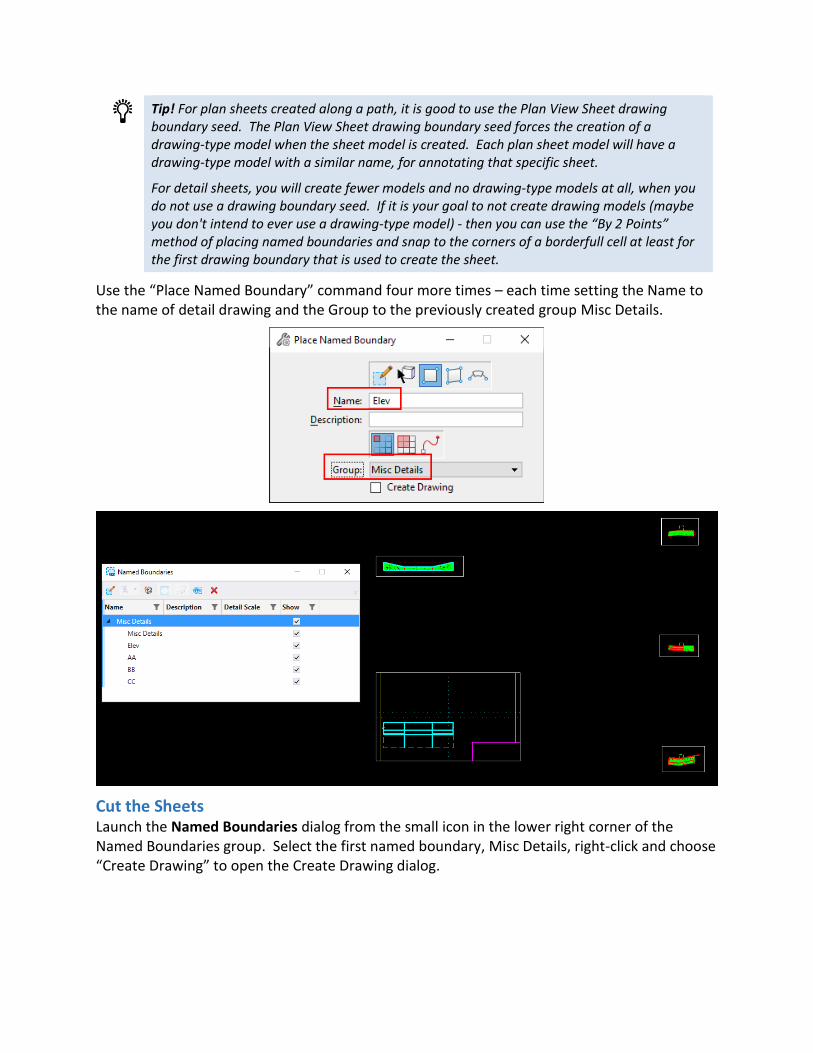
Tip! For plan sheets created along a path, it is good to use the Plan View Sheet drawing boundary seed. The Plan View Sheet drawing boundary seed forces the creation of a drawing-type model when the sheet model is created. Each plan sheet model will have a drawing-type model with a similar name, for annotating that specific sheet.
For detail sheets, you will create fewer models and no drawing-type models at all, when you do not use a drawing boundary seed. If it is your goal to not create drawing models (maybe you don't intend to ever use a drawing-type model) - then you can use the “By 2 Points” method of placing named boundaries and snap to the corners of a borderfull cell at least for the first drawing boundary that is used to create the sheet.
Use the “Place Named Boundary” command four more times – each time setting the Name to the name of detail drawing and the Group to the previously created group Misc Details.
Cut the Sheets Launch the Named Boundaries dialog from the small icon in the lower right corner of the Named Boundaries group. Select the first named boundary, Misc Details, right-click and choose “Create Drawing” to open the Create Drawing dialog.

On the Create Drawing dialog, check the box next to “Create Sheet Model” and set the Detail Scale to be the same as the Annotation Scale of the Named Boundaries model.
Tip! When the named boundary is the same size as the view port in the sheet - the Detail Scale ends up being exactly the Annotation Scale (Drawing Scale or Print Scale). When the named boundary is smaller than the view port of the sheet - you need to check the Detail Scale and reset it to the chosen Drawing Scale. Setting the intended print scale in the Named Boundaries model makes all choices downstream a bit easier.

With “Open Model” checked on – clicking [OK] will create the sheet model in the Detail Sheets file. The picture below shows the sheet, the reference to the first detail drawing, the border, the title block, and drawing aids that are available.
The named boundary is centered on the sheet and not correctly positioned within the border. Use the snapping points available from the borderfull cell to move the reference into its correct position in the sheet.
The Detail Callout and construction class elements may be toggled off in the View Attributes. Level Display may also be used to adjust the view.
Adding the Other Detail Named Boundaries The named boundaries are stored in the “Named Boundaries” model, so that model must be the active model in order to proceed.
Using the Named Boundaries dialog, right-click on another named boundary for a detail that should appear in the same sheet and choose “Create Drawing”.

Ensure that “Create Sheet Model” is selected, that the Sheets: field shows the name of the sheet model that was previously created, and set the Detail Scale: to match the Drawing Scale.
The named boundary will be attached and clipped in the sheet, and will need to be moved from its initial center location to the correct position in the sheet. AccuDraw can be used to align the references in the sheet.
Return to the “Named Boundaries” model, and use “Create Drawing” in the Named Boundaries dialog, to add and position the other details in the same sheet.

Annotations are most easily drawn directly into the sheet, where you can see how everything is positioned.