Article · Web viewThis approach allows the evolving nature of dynamic fracture to be taken into...
18
Dynamic fracture effects on remote stress amplification in AGR graphite bricks Timothy Crump ab , Guilhem Ferté c , Paul Mummery a , Andrey Jivkov a , Philippe, Martinuzzi b , Van-Xuan Tran b* a MACE, University of Manchester, Sackville Street, Manchester, UK b Modelling and Simulation Centre, EDF Energy R&D UK Centre, Manchester, UK c EDF R&D, 7 Boulevard Gaspard Monge, 91 120 Palaiseau, France Abstract An initial investigation, using a newly developed tool within Code_Aster known as the eXtended Finite Element Method with cohesive elements (XCZM), has been undertaken to investigate the dynamic stress state of a 2D graphite brick geometry under the loading of a dynamically propagating crack. This was with the aim of investigating the phenomenon known as ‘prompt secondary cracking’ (PSC) and any effects geometrical features may have on the remote stress state of the brick. It was seen that the PSC mechanism could be modelled, with methane holes possibly having an effect on this phenomenon by altering the initial static stress state. Keywords: Graphite, Prompt Secondary Cracking, Dynamic Fracture *
Transcript of Article · Web viewThis approach allows the evolving nature of dynamic fracture to be taken into...

Dynamic fracture effects on remote stress amplification in AGR graphite bricks
Timothy Crumpab, Guilhem Fertéc, Paul Mummerya, Andrey Jivkova, Philippe, Martinuzzib, Van-Xuan Tranb*
aMACE, University of Manchester, Sackville Street, Manchester, UKbModelling and Simulation Centre, EDF Energy R&D UK Centre, Manchester, UK
cEDF R&D, 7 Boulevard Gaspard Monge, 91 120 Palaiseau, France
Abstract
An initial investigation, using a newly developed tool within Code_Aster known as the eXtended Finite Element Method with cohesive elements (XCZM), has been undertaken to investigate the dynamic stress state of a 2D graphite brick geometry under the loading of a dynamically propagating crack. This was with the aim of investigating the phenomenon known as ‘prompt secondary cracking’ (PSC) and any effects geometrical features may have on the remote stress state of the brick. It was seen that the PSC mechanism could be modelled, with methane holes possibly having an effect on this phenomenon by altering the initial static stress state.
Keywords: Graphite, Prompt Secondary Cracking, Dynamic Fracture
*
1. Introduction
There are 14 AGRs in the UK, which are moderated by Gilsocarbon Graphite and cooled by CO2. The core is built from cylindrical bricks of graphite, shown in Fig. 1(a), ranging in size and shape between reactor generations, the role they play within the structure, and the key-keyway system as described by Neighbour (2007). Further to the graphite bricks acting as the moderator, they also provide the structural integrity to the whole core and from this it is an objective to assess the state of these bricks, and any possible physical phenomena that may occur while in operation, within the reactor environment.
One postulated consequence of crack initiation and growth is ‘Prompt Secondary Cracking’ (PSC). This has been observed in experiments on virgin (unirradiated) graphite, but not in operational reactors to-date. It is understood to occur due to the dynamic effects of an initial crack in a keyway corner of a brick, illustrated in Fig. 1(b). The initial crack is thought to generate dynamic effects such as surface and shear strain waves, which propagate through the brick, to combine constructively at the opposing keyway corner, promptly initiating a second dynamic brittle crack.
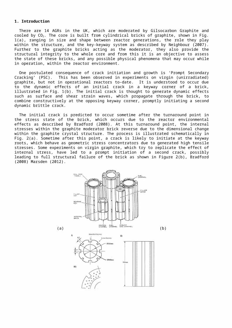
The initial crack is predicted to occur sometime after the turnaround point in the stress state of the brick, which occurs due to the reactor environmental effects as described by Bradford (2008). At this turnaround point, the internal stresses within the graphite moderator brick reverse due to the dimensional change within the graphite crystal structure. The process is illustrated schematically in Fig. 2(a). Sometime after this point, a crack is likely to initiate at the keyway roots, which behave as geometric stress concentrators due to generated high tensile stresses. Some experiments on virgin graphite, which try to replicate the effect of internal stress, have led to a prompt initiation of a second crack, possibly leading to full structural failure of the brick as shown in Figure 2(b), Bradford (2008) Marsden (2012).
(a) (b)
Fig. 1. (a) The arrangement of graphite bricks within an AGR core; (b) the geometry and cross-section of a graphite moderator brick: i) a lateral cross-section, ii) a side view showing the height and iii) a close-up of a quarter of the top face of a brick showing the methane holes, Neighbour (2007) .
Standard (static) fracture theory considers systems as quasi-static, where the kinetic energy is assumed to be insignificant compared to the internal energy within the Griffiths energy balance for the system. This assumption is valid in the majority of industrial scenarios and avoids the added complexity of dynamic fracture mechanics in predicting when a component will fail. However, inertial effects may be significant in some cases for AGR graphite brick fracture. Consequently, the inertial effects of component failure need to be understood, as they may impact the geometry of the subsequent crack and generate higher stresses, which could lead to the introduction of another crack in the same brick or its neighbours.
The work presented here uses a newly developed modelling technique within EDF R&D’s Finite Element Modelling (FEM) open-source code: Code_Aster. The technique combines the advantages of Cohesive Elements to represent the material fracture with the benefits of representing a non-pre-meshed crack with the eXtended Finite Element Modelling (XFEM), Ferté (2014). This approach allows the evolving nature of dynamic fracture to be taken into account, with initial crack propagation, arrest and possible secondary initiation.
(a) (b)
Fig. 2. (a) Schematic of the stress reversal experienced at the turnaround point; (b) illustrative example of the end result of prompt secondary cracking, Neighbour (2007).
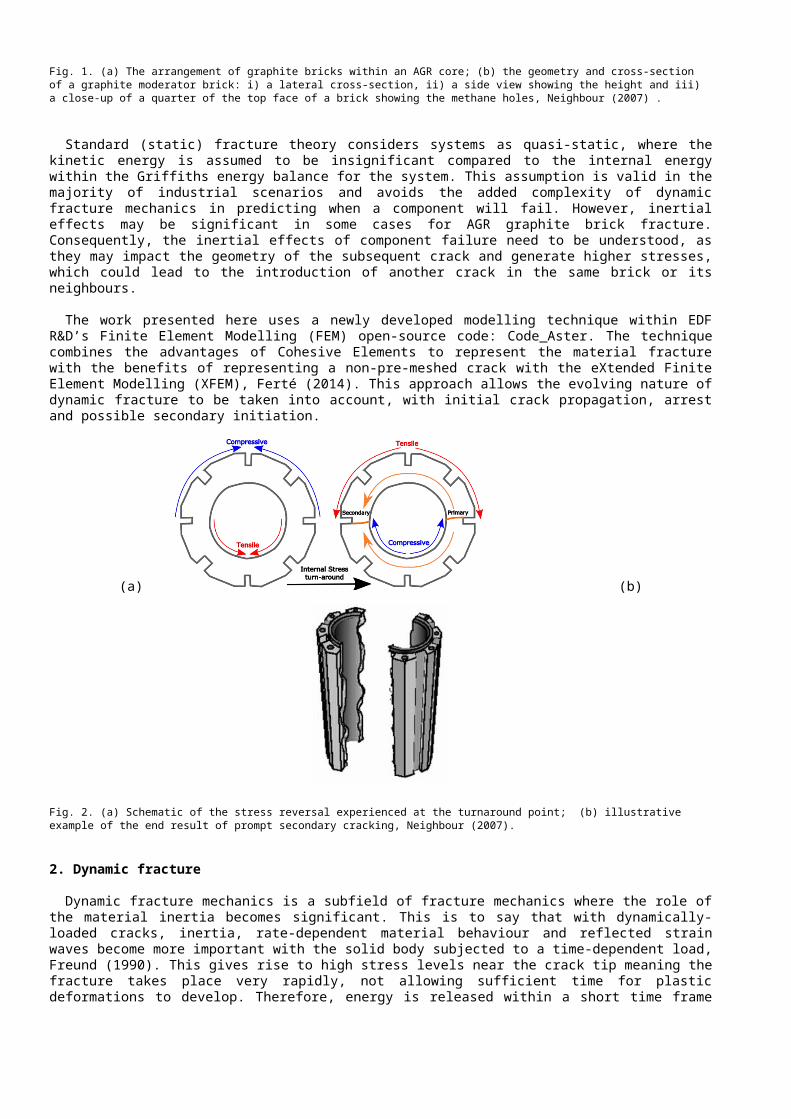
2. Dynamic fracture
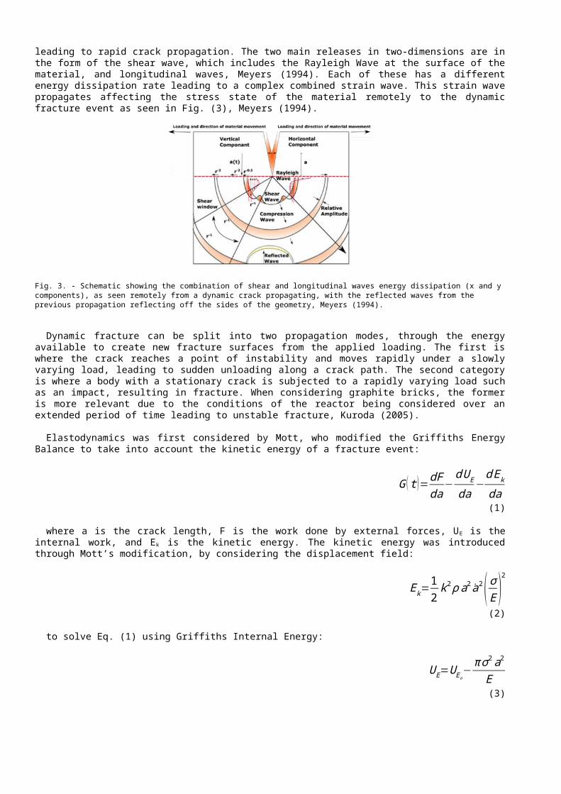
Dynamic fracture mechanics is a subfield of fracture mechanics where the role of the material inertia becomes significant. This is to say that with dynamically-loaded cracks, inertia, rate-dependent material behaviour and reflected strain waves become more important with the solid body subjected to a time-dependent load, Freund (1990). This gives rise to high stress levels near the crack tip meaning the fracture takes place very rapidly, not allowing sufficient time for plastic deformations to develop. Therefore, energy is released within a short time frame leading to rapid crack propagation. The two main releases in two-dimensions are in the form of the shear wave, which includes the Rayleigh Wave at the surface of the material, and longitudinal waves, Meyers (1994). Each of these has a different energy dissipation rate leading to a complex combined strain wave. This strain wave propagates affecting the stress state of the material remotely to the dynamic fracture event as seen in Fig. (3), Meyers (1994).
Fig. 3. - Schematic showing the combination of shear and longitudinal waves energy dissipation (x and y components), as seen remotely from a dynamic crack propagating, with the reflected waves from the previous propagation reflecting off the sides of the geometry, Meyers (1994).
Dynamic fracture can be split into two propagation modes, through the energy available to create new fracture surfaces from the applied loading. The first is where the crack reaches a point of instability and moves rapidly under a slowly varying load, leading to sudden unloading along a crack path. The second category is where a body with a stationary crack is subjected to a rapidly varying load such as an impact, resulting in fracture. When considering graphite bricks, the former is more relevant due to the conditions of the reactor being considered over an extended period of time leading to unstable fracture, Kuroda (2005).
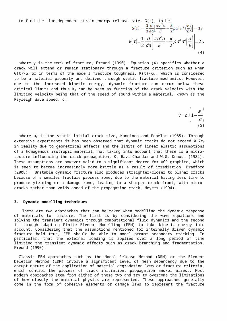
Elastodynamics was first considered by Mott, who modified the Griffiths Energy Balance to take into account the kinetic energy of a fracture event:
G (t )=dFda
−d UE
da−
d Ek
da (1)
where a is the crack length, F is the work done by external forces, UE is the internal work, and Ek is the kinetic energy. The kinetic energy was introduced through Mott’s modification, by considering the displacement field:
Ek=12
k2 ρ a2 a2( σE )
2
(2)
to solve Eq. (1) using Griffiths Internal Energy:
U E=U Eo−π σ 2a2
E (3)
to find the time-dependent strain energy release rate, G(t), to be:
G ( t )=12
dda [ π σ 2a
E−k
2ρ a2 a2( σ
E )]=2 γ (4)
where γ is the work of fracture, Freund (1990). Equation (4) specifies whether a crack will extend or remain stationary through a fracture criterion such as when G(t)>Gc or in terms of the mode I fracture toughness, K(t)>KIc, which is considered to be a material property and derived through static fracture mechanics. However, due to the increased kinetic energy, dynamic fracture can occur below these critical limits and thus KI can be seen as function of the crack velocity with the limiting velocity being that of the speed of sound within a material, known as the Rayleigh Wave speed, cr:
v=cr(1−ao
a ) (5)
where ao is the static initial crack size, Kanninen and Popelar (1985). Through extensive experiments it has been observed that dynamic cracks do not exceed 0.7cr in reality due to geometrical effects and the limits of linear elastic assumptions of a homogenous isotropic material, not taking into account that there is a micro-texture influencing the crack propagation, K. Ravi-Chandar and W.G. Knauss (1984). These assumptions are however valid to a significant degree for AGR graphite, which is seen to become increasingly more brittle as a result of irradiation, Bradford (2008). Unstable dynamic fracture also produces straighter/closer to planar cracks because of a smaller fracture process zone, due to the material having less time to produce yielding or a damage zone, leading to a sharper crack front, with micro-cracks rather than voids ahead of the propagating crack, Meyers (1994).
3. Dynamic modelling techniques
There are two approaches that can be taken when modelling the dynamic response of materials to fracture. The first is by considering the wave equations and solving the transient dynamics through computational fluid dynamics and the second is through adapting Finite Element Modelling (FEM) to take kinetic energy into account. Considering that the assumptions mentioned for internally driven dynamic fracture hold true, FEM should be able to model prompt secondary cracking. In particular, that the external loading is applied over a long period of time limiting the transient dynamic affects such as crack branching and fragmentation, Freund (1990).
Classic FEM approaches such as the Nodal Release Method (NRM) or the Element Deletion Method (EDM) involve a significant level of mesh dependency due to the abrupt nature of the application of material degradation laws or fracture criteria, which control the process of crack initiation, propagation and/or arrest. Most modern approaches stem from either of these two and try to overcome the limitations of how closely the material physics are represented. These approaches generally come in the form of cohesive elements or damage laws to represent the fracture process and adaptive meshing techniques such as the eXteneded Finite Element Method (XFEM) or mesh refinement, to overcome the mesh dependency. Each of these has advantages and disadvantages, with cohesive elements through Cohesive Zone Modelling (CZM) used more commonly to model brittle fracture, and Damage Mechanics (DM) used more for ductile fracture modelling.
In this paper, a recent development within Code_Aster known as the eXtended Finite Element method with Cohesive Zones (XCZM) is used to model an initial dynamic crack initiation, propagation and arrest, which then could subsequently
initiate a secondary fracture event remotely, due to the time-dependent (and crack-tip velocity dependent) stress amplification.
3.1. Cohesive Elements
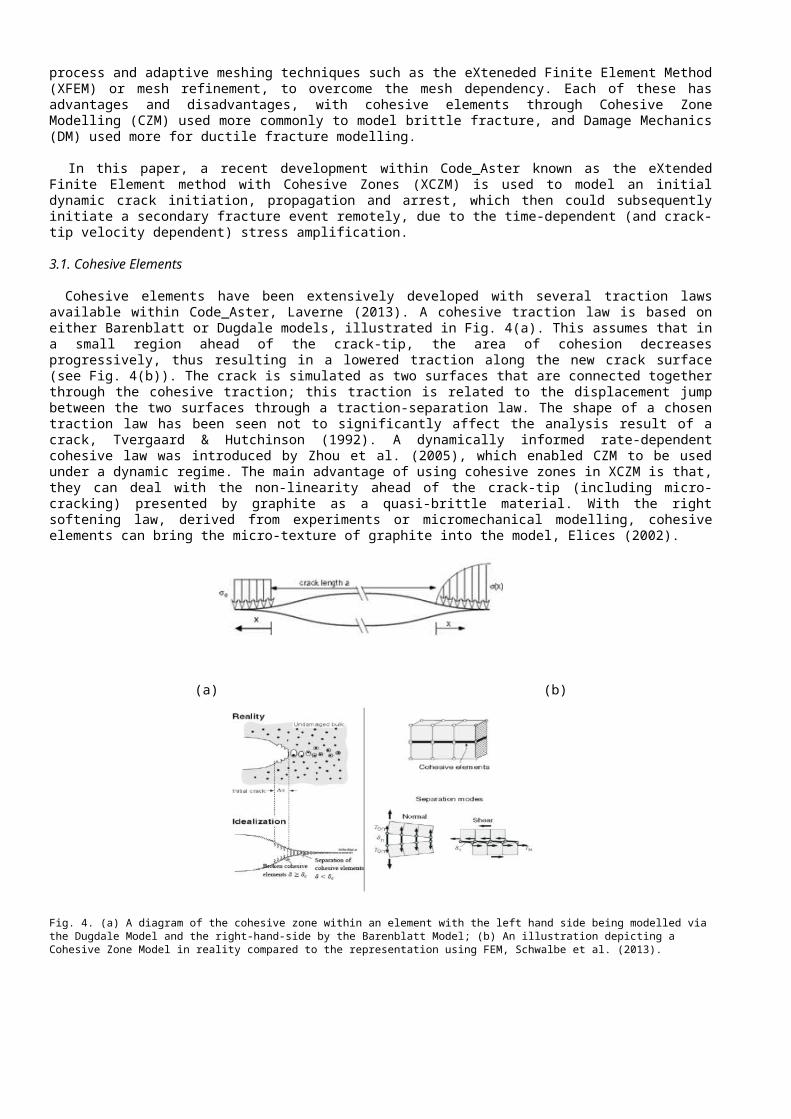
Cohesive elements have been extensively developed with several traction laws available within Code_Aster, Laverne (2013). A cohesive traction law is based on either Barenblatt or Dugdale models, illustrated in Fig. 4(a). This assumes that in a small region ahead of the crack-tip, the area of cohesion decreases progressively, thus resulting in a lowered traction along the new crack surface (see Fig. 4(b)). The crack is simulated as two surfaces that are connected together through the cohesive traction; this traction is related to the displacement jump between the two surfaces through a traction-separation law. The shape of a chosen traction law has been seen not to significantly affect the analysis result of a crack, Tvergaard & Hutchinson (1992). A dynamically informed rate-dependent cohesive law was introduced by Zhou et al. (2005), which enabled CZM to be used under a dynamic regime. The main advantage of using cohesive zones in XCZM is that, they can deal with the non-linearity ahead of the crack-tip (including micro-cracking) presented by graphite as a quasi-brittle material. With the right softening law, derived from experiments or micromechanical modelling, cohesive elements can bring the micro-texture of graphite into the model, Elices (2002).
(a) (b)
Fig. 4. (a) A diagram of the cohesive zone within an element with the left hand side being modelled via the Dugdale Model and the right-hand-side by the Barenblatt Model; (b) An illustration depicting a Cohesive Zone Model in reality compared to the representation using FEM, Schwalbe et al. (2013).
3.2. eXtended Finite Element Method (XFEM)
The extended finite element method (XFEM) is an extension of the classical FEM introduced by Moës, Dolbow and Belytschko (1999). It uses the theory of Partition of Unity to describe a crack via level sets rather than a pre-meshed crack which means the crack can be informed by its own growth and take the time-dependent effects of dynamic crack propagation, such as reflected strain waves, into account. As seen in Fig. 5(a), there are two level sets: the first is the normal level set (LSN), which represents the distance of the point from the crack surface, and the second is the tangential level set (LST) that represents the distance from the crack front, which will be the newly created crack area, EDF R&D. (2015). Fig. 5(b) shows the XFEM element enrichment; a combination of the classical FEM function and Heaviside nodal shape function to represent the discontinuity in displacement across the crack (Eqn. 6), EDF R&D (2015). Element enrichment is applied by reference to the level sets.
(a) (b)
Fig. 5. (a) The level set description of an XFEM crack showing both the normal and tangential level sets schematically. (b) XFEM crack representation: triangles are enriched with discontinuous Heaviside function, EDF R&D. (2015).
u ( x )=∑
ia i N i(x )+∑
ibi N i ( x ) H (x) (6)
3.3. eXtended Finite Element Modelling with Cohesive Elements (XCZM)
The XCZM modelling approach is designed to combine the advantages of meso-scale cohesive zone modelling with the computational efficiency of a not having a pre-meshed crack, using the XFEM approach. This combination is able to investigate a dynamically-informed primary brittle crack initiation, propagation and arrest. It may also possibly capture the stress amplification effects due to the strain wave propagation, then initiate a secondary dynamically-informed crack and consider its propagation and arrest. XCZM is implemented via an algorithm in Code_Aster, which starts with an initially rigid cohesive zone as can be seen in Figure 6 and then computes a potential crack surface, which is an area where the crack may propagate. An interface law that is capable of handling the initial crack is then introduced, with the crack front defined as the boundary between this cracked surface and a fully adherent zone. This was implemented and validated in Code_Aster by EDF R&D in France, and the procedure for this is as follows, from Fig, 6, Ferté (2014):
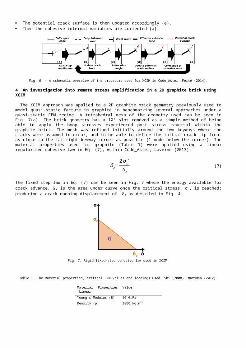
Given a potential crack surface, the equilibrium state is computed (b). The crack front is then updated based on the computed cohesive state (c). An angle of propagation is then determined along the crack front (d). The potential crack surface is then updated accordingly (e). Then the cohesive internal variables are corrected (a).
Fig. 6. - A schematic overview of the procedure used for XCZM in Code_Aster, Ferté (2014).
4. An investigation into remote stress amplification in a 2D graphite brick using XCZM
The XCZM approach was applied to a 2D graphite brick geometry previously used to model quasi-static facture in graphite in benchmarking several approaches under a quasi-static FEM regime. A tetrahedral mesh of the geometry used can be seen in Fig. 7(a). The brick geometry has a 10° slot removed as a simple method of being able to apply the hoop stresses experienced post stress reversal within the graphite brick. The mesh was refined initially around the two keyways where the cracks were assumed to occur, and to be able to define the initial crack tip front as close to the far right keyway corner as possible (1 node below the corner). The material properties used for graphite (Table 1) were applied using a linear regularised cohesive law in Eq. (7), within Code_Aster, Laverne (2013):
δ c=2σc
2
Gc (7)
The fixed step law in Eq. (7) can be seen in Fig. 7 where the energy available for crack advance, G, is the area under curve once the critical stress, σc, is reached; producing a crack opening displacement of δc as detailed in Fig. 4.
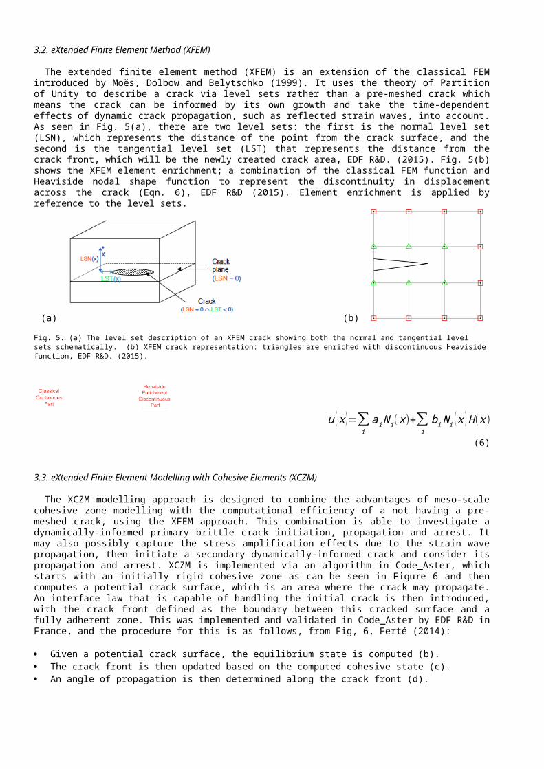
Fig. 7. Rigid fixed-step cohesive law used in XCZM.
Table 1. The material properties, critical CZM values and loadings used, Shi (2008), Marsden (2012).
Material Properties (Linear) Value
Young’s Modulus (E) 10 G.Pa
Density (ρ) 1800 kg.m-3
Poisson’s Ratio (ν) 0.2
Gc 140 J.m-2
σc 25 M.Pa
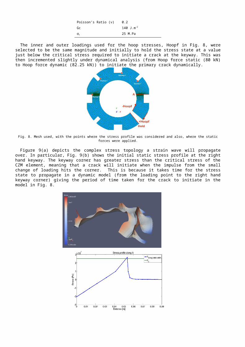
The inner and outer loadings used for the hoop stresses, Hoopf in Fig. 8, were selected to be the same magnitude and initially to hold the stress state at a value just below the critical stress required to initiate a crack at the keyway. This was then incremented slightly under dynamical analysis (from Hoop force static (80 kN) to Hoop force dynamic (82.25 kN)) to initiate the primary crack dynamically.
Fig. 8. Mesh used, with the points where the stress profile was considered and also, where the static forces were applied.
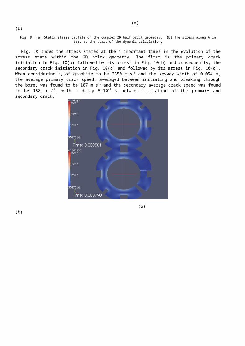
Figure 9(a) depicts the complex stress topology a strain wave will propagate over. In particular, Fig. 9(b) shows the initial static stress profile at the right hand keyway. The keyway corner has greater stress than the critical stress of the CZM element, meaning that a crack will initiate when the impulse from the small change of loading hits the corner. This is because it takes time for the stress state to propagate in a dynamic model (from the loading point to the right hand keyway corner) giving the period of time taken for the crack to initiate in the model in Fig. 8.
(a) (b)
Fig. 9. (a) Static stress profile of the complex 2D half brick geometry. (b) The stress along A in (a), at the start of the dynamic calculation.
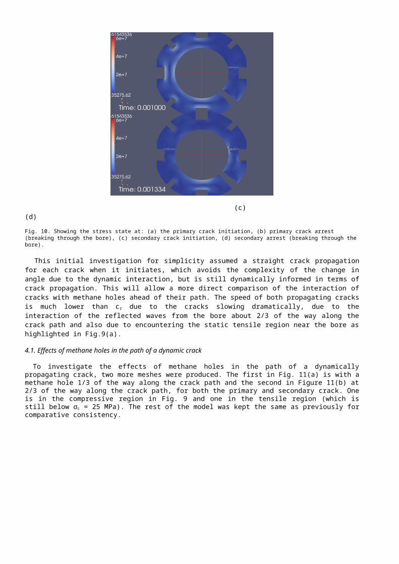
Fig. 10 shows the stress states at the 4 important times in the evolution of the stress state within the 2D brick geometry. The first is the primary crack initiation in Fig. 10(a) followed by its arrest in Fig. 10(b) and consequently, the secondary crack initiation in Fig. 10(c) and followed by its arrest in Fig. 10(d). When considering c r of graphite to be 2350 m.s-1 and the keyway width of 0.054 m, the average primary crack speed, averaged between initiating and breaking through the bore, was found to be 187 m.s-1 and the secondary average crack speed was found to be 158 m.s -1, with a delay 5.10-4 s between initiation of the primary and secondary crack.
(a) (b)
(c) (d)
Fig. 10. Showing the stress state at: (a) the primary crack initiation, (b) primary crack arrest (breaking through the bore), (c) secondary crack initiation, (d) secondary arrest (breaking through the bore).
This initial investigation for simplicity assumed a straight crack propagation for each crack when it initiates, which avoids the complexity of the change in angle due to the dynamic interaction, but is still dynamically informed in terms of crack propagation. This will allow a more direct comparison of the interaction of cracks with methane holes ahead of their path. The speed of both propagating cracks is much lower than c r due to the cracks slowing dramatically, due to the interaction of the reflected waves from the bore about 2/3 of the way along the crack path and also due to encountering the static tensile region near the bore as highlighted in Fig.9(a).
4.1. Effects of methane holes in the path of a dynamic crack
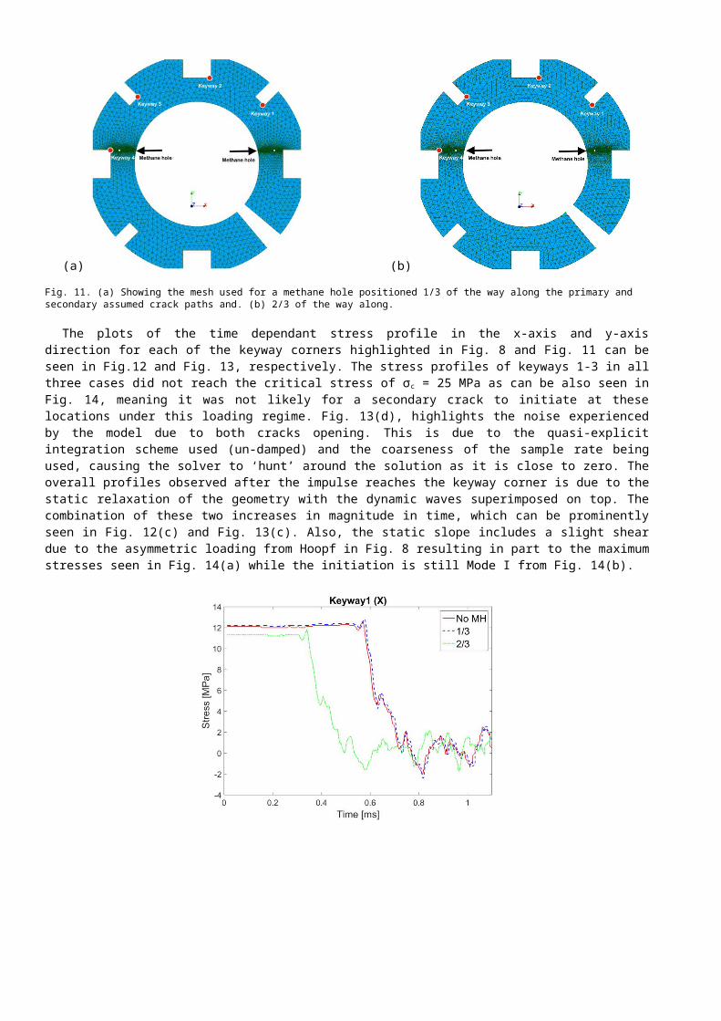
To investigate the effects of methane holes in the path of a dynamically propagating crack, two more meshes were produced. The first in Fig. 11(a) is with a methane hole 1/3 of the way along the crack path and the second in Figure 11(b) at 2/3 of the way along the crack path, for both the primary and secondary crack. One is in the compressive region in Fig. 9 and one in the tensile region (which is still below σc = 25 MPa). The rest of the model was kept the same as previously for comparative consistency.
(a) (b)
Fig. 11. (a) Showing the mesh used for a methane hole positioned 1/3 of the way along the primary and secondary assumed crack paths and. (b) 2/3 of the way along.
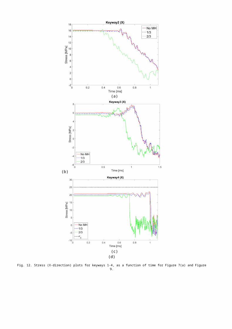
The plots of the time dependant stress profile in the x-axis and y-axis direction for each of the keyway corners highlighted in Fig. 8 and Fig. 11 can be seen in Fig.12 and Fig. 13, respectively. The stress profiles of keyways 1-3 in all three cases did not reach the critical stress of σc = 25 MPa as can be also seen in Fig. 14, meaning it was not likely for a secondary crack to initiate at these locations under this loading regime. Fig. 13(d), highlights the noise experienced by the model due to both cracks opening. This is due to the quasi-explicit integration scheme used (un-damped) and the coarseness of the sample rate being used, causing the solver to ‘hunt’ around the solution as it is close to zero. The overall profiles observed after the impulse reaches the keyway corner is due to the static relaxation of the geometry with the dynamic waves superimposed on top. The combination of these two increases in magnitude in time, which can be prominently seen in Fig. 12(c) and Fig. 13(c). Also, the static slope includes a slight shear due to the asymmetric loading from Hoopf in Fig. 8 resulting in part to the maximum stresses seen in Fig. 14(a) while the initiation is still Mode I from Fig. 14(b).
(a) (b)
(c) (d)
Fig. 12. Stress (X-direction) plots for keyways 1-4, as a function of time for Figure 7(a) and Figure 9.
When comparing the initial static stress experienced at each of these keyway corners, it can be seen that the position of the methane hole along the crack path induces a clear difference between the stress states. The static difference above σ c is due to the difference in stress state required to initiate the crack at the corner and the stress state required to initiate it where the crack is inserted just below this (1 element). This would mean it would be slightly higher (static) above the critical stress because the corner is a stress concentrator. This can be seen in Fig, 13(d) where the geometries with methane holes at 1/3 and 2/3, start at one stress state, whereas the one with no methane hole starts at a slightly higher one.
(a) (b)
(c) (d)
Fig. 13. Stress (Y-direction) plots for keyways 1-4, as a function of time for Figure 7(a) and Figure 9.
The methane hole 1/3 of the way along the crack path does not change the stress profile compared to the one without a hole (due to not arresting at the methane hole, and its position not being significant in changing the initial stress state), as seen in Fig. 9(b). However, for the methane hole 2/3 of the way along, the primary crack initiates earlier because the position is significant in terms of the dynamic crack propagating, and it is also at a point where there is less energy to maintain crack propagation. It can be seen that the crack with the methane hole 2/3 of the way along has slowed due to the reflected waves from the bore and arrests at the methane hole. The stress then propagates around the methane hole and initiates again at the opposite side of the hole and continues to propagate towards the bore.
(a) (b)
Fig. 14. Comparison of maximum stress experienced at each keyway; (a) x-direction; y-direction.
The positions of the methane holes highlight the influence of two possible dynamic processes that may cause crack arrest: the crack runs out of momentum (G) or via reflected waves that interact with the crack tip energy state superposing de-constructively which may cause ‘stop-start’ crack propagation. This uses Motts assumption that instantly after initiation a crack tip is equivalent to a point moving through graphite material space along a periodic potential which is not time dependant, such that arrest occurs when (see Fig. 15):
σ ct (a , t )+σ r (r , t )<σc (7)
Fig. 15. Maximum stress experienced at each keyway.
where σct(a,t) is the crack tip stress state, dependant on the crack length, a, in time where a=x when t=0, σ r(r,t) is the stress from a reflected wave, which is dependant on r= (d-a) in time and σc(r) is the fracture toughness at position r and is not strain rate/time dependant.
Fig. 16. Showing the 3 points around the methane hole considered.
The stress profile for 3 points around the methane hole (Fig. 16) can be seen in Fig. 17. The methane hole receives a large increase in stress in the x-component as the crack impacts the methane hole (compressive waves) at the same time for each methane hole position, which subsequently flips the y-component stress from compressive to tensile thereby re-initiating the primary crack. This is most significant for the 45o angle and suggests the crack may change direction on re-initiation, and also that the primary crack may change direction due to the presence of the methane holes. This may have consequences when interpreting crack profiles and positions observed at reactor outages.
(a) (b)Fig. 17. (a) Showing the stress profile for (a) the x-component and (b) the y-component over time for three points on the methane hole: top, bottom and at a 45o angle as seen in Figure 10.
5. Conclusions
The stress state for a 2D graphite brick geometry was investigated with an applied static hoop stress. This was then adjusted until the stress state was such that a primary crack was initiated. It was subsequently observed that a secondary crack also initiated at a distant keyway some time after the initial crack, due to time-dependant stress amplification there. This was from the dynamic effects of a propagating crack using cohesive elements inserted using XFEM. It was also seen that the dynamically propagating primary and secondary cracks slow down significantly as they approach the bore of the brick, due to strain wave reflection, and other possible mechanisms.
Methane holes were added into the brick face geometry, for each of the crack paths, to observe the effects this had on the crack propagating speeds and delay times of initiating primary and secondary cracks. It is concluded that the combination of XFEM and cohesive elements (XCZM) could be an effective and efficient approach for the analysis of such phenomena as PSC in quasi-brittle materials such as nuclear graphite. Additional work will be undertaken to assess this possibility further.
Acknowledgements
The main author would like to thank: the on-going support of EPSRC through the Engineering Doctorate Training Centre (EP/G037426/1), the Dalton Nuclear Institute and the insight given by his previous and current supervisors at the University of Manchester in producing this work.
This work was also done as part of a TSB collaborative project between EDF Energy R&D UK Centre, EDF Energy Generation, EDF R&D in France and the University of Manchester. The authors gratefully acknowledge EDF Energy Generation for their valuable input data and support. The views expressed in this paper are those of the authors, and not necessarily those of EDF Energy Generation. Technical support for this work from EDF R&D is greatly appreciated.
References
Bradford M. R., Steer. A. G. (2008). “A structurally-based model of irradiated graphite properties”. Journal of Nuclear Materials, 381(1–2):137 – 144.
EDF R&D. (2015). Code_Aster Training Presentation (17) on XFEM.M. Elices, G.V. Guinea, J. Gómez, J. Planas, (2002). “The cohesive zone model: advantages, limitations and challenges”,
Engineering Fracture Mechanics, Volume 69, Issue 2, Pages 137-163, ISSN 0013-7944, Ferté .G. Mansouri.A. (2014). “Propagation De Fissures Cohesives En 3 Dimensions”. EDF R&D, Fr. Freund L. B. (1990). “Dynamic Fracture Mechanics”. Cambridge Univ Press Cambridge Massachusetts. Kanninen. M.F. and C.L. Popelar. (1985). “Advanced fracture mechanics”. Oxford University Press.Ravi-Chandar. K. and Knauss. W.G. (1984). “An experimental investigation into dynamic fracture. part ii : microstructural
aspects”. International Journal of Fracture, 26:141-154.Kuroda, M., Fok, S. L., Marsden, B. J., Oyadiji, S, O. (2005) “Dynamics and generation of stress waves in cracked graphite
moderator bricks”. Nuclear Engineering Design ;235(5):557–73. Laverne. J. (2013). “Note of use of the models of cohesive zones”. Code_Aster Documentation.Marsden, B. J., and Hall, G. N. (2012). “Graphite in Gas-cooled Reactors”. Comprehensive Nuclear Materials, Elsevier, UK.Meyers .A.(1994). “Dynamic Behaviour Of Materials”. John Wiley & Sons.Neighbour. G. B. (2007). “Management of Ageing Processes in Graphite Reactor Cores”. Royal Society of
Chemistry.Volume 309. Schwalbe, K., Scheider, I. & Cornec, A., (2013). “Guidelines for Applying Cohesive Models to the Damage. Behaviour of
Engineering Materials and Structures”. Springer. Berlin, Heidelberg.Li Shi, Haiyan Li, Zhenmin Zou, Alex S.L. Fok, Barry J. Marsden, Andrew Hodgkins, Paul M. Mummery, James Marrow.
(2008). “Analysis of crack propagation in nuclear graphite using three-point bending of sandwiched specimens”, Journal of Nuclear Materials, Volume 372, Issues 2–3, 31, Pages 141-151, ISSN 0022-3115,
Moës N, Dolbow J, Belytschko T. (1999) A finite element method for crack growth without remeshing. Int J Numer Methods Eng. John Wiley & Sons, Ltd.; Sep 10;46(1):131–50.
Tvergaard, V. Hutchinson, J., (1996). “Effect of strain dependent cohesive zone model on predictions of interface crack growth”. International Journal of Solids and structures, 33(2), pp.3297–3308.
F. Zhou, J.F., Molinari, and Shioya, T. (2005) “A rate-dependent cohesive model for simulating dynamic crack propagation in brittle materials”. Engineering fracture mechanics, 72:1383 -1410, 2005.