CREEP CRACK GROWTH PREDICTION IN THICK …spiral.imperial.ac.uk/bitstream/10044/1/94/1/Creep crack...
25
CREEP CRACK INITIATION AND GROWTH IN THICK SECTION STEEL PIPES UNDER INTERNAL PRESSURE K. Wasmer, K. M. Nikbin * and G. A. Webster Dept. of Mechanical Engineering Imperial College London, SW7 2BX ABSTRACT In this study, creep crack growth in pre-cracked straight and bent pipes of a 9% Cr-steel, containing multiple cracks and tested at 625°C under static and slow cyclic pressure loading, is investigated. The results have been interpreted in terms of the creep fracture mechanics parameter C* and compared with data obtained on standard compact tension (CT) specimens of the same material and batch. In making the assessments, reference stress methods have been used to determine C* for the pipes. Several formulae can be employed for calculating reference stress depending on whether it is based on a ‘global’ or a ‘local’ collapse mechanism. When using this approach, it is shown that the values obtained for C* are sensitive to the material properties, geometric dimensions and crack lengths chosen in the analysis. However, it has been found that, the most satisfactory comparison of crack growth rates with standard CT specimen data is obtained when the ‘global’ reference stress solution is used in conjunction with the nominal thickness of a pipe and the mean parent uniaxial creep properties. Also, no difference has been observed between the crack growth rates measured in the straight and bent pipes. The main effect of the slow pressure cycling was to cause an acceleration in the early stages of cracking. KEY words: Defects, fracture mechanics, creep crack growth, pipe components. Corresponding author * K. M. Nikbin, Mechanical Engineering, Imperial College, London, SW7 2AZ, fax: 0207-594- 7107, e-mail [email protected]
Transcript of CREEP CRACK GROWTH PREDICTION IN THICK …spiral.imperial.ac.uk/bitstream/10044/1/94/1/Creep crack...

CREEP CRACK INITIATION AND GROWTH IN THICK SECTION STEEL
PIPES UNDER INTERNAL PRESSURE
K. Wasmer, K. M. Nikbin* and G. A. Webster
Dept. of Mechanical Engineering
Imperial College
London, SW7 2BX
ABSTRACT
In this study, creep crack growth in pre-cracked straight and bent pipes of a 9% Cr-steel,
containing multiple cracks and tested at 625°C under static and slow cyclic pressure loading,
is investigated. The results have been interpreted in terms of the creep fracture mechanics
parameter C* and compared with data obtained on standard compact tension (CT)
specimens of the same material and batch. In making the assessments, reference stress
methods have been used to determine C* for the pipes. Several formulae can be employed
for calculating reference stress depending on whether it is based on a ‘global’ or a ‘local’
collapse mechanism. When using this approach, it is shown that the values obtained for C*
are sensitive to the material properties, geometric dimensions and crack lengths chosen in
the analysis. However, it has been found that, the most satisfactory comparison of crack
growth rates with standard CT specimen data is obtained when the ‘global’ reference stress
solution is used in conjunction with the nominal thickness of a pipe and the mean parent
uniaxial creep properties. Also, no difference has been observed between the crack growth
rates measured in the straight and bent pipes. The main effect of the slow pressure cycling
was to cause an acceleration in the early stages of cracking.
KEY words: Defects, fracture mechanics, creep crack growth, pipe components.
Corresponding author* K. M. Nikbin, Mechanical Engineering, Imperial College, London, SW7 2AZ, fax: 0207-594-
7107, e-mail [email protected]

NOMENCLATURE
A Norton power law creep constant in Eq. (3)
C* steady state creep fracture mechanics parameter
C*ref value of C* determined from reference stress methods
D constant in Eq. (1)
Di constant in Eq. (5)
J elastic-plastic fracture mechanics parameter
K stress intensity factor
Ri, Re internal and external radii of cylinder
W cylinder wall thickness
a, aini, afin depth of surface crack, initial and final depths of the surface crack
bate (a,c) function of dimensions
c, cini, cfin half-length of surface crack, initial and final half-lengths of surface crack
a creep crack growth rate
n Norton stress index in power law creep Eq. (3)
p applied pressure
ti incubation time
Δa incubation distance
φ constant in Eq. (1)
φi constant in Eq. (5)
ε ˙, ε ˙min creep strain rate and minimum creep strain rates
ε ˙ref creep strain rate at reference stress
σ stress
σb, σm bending stress, membrane stress
σref reference stress
g(ζ), ζ functions of geometry
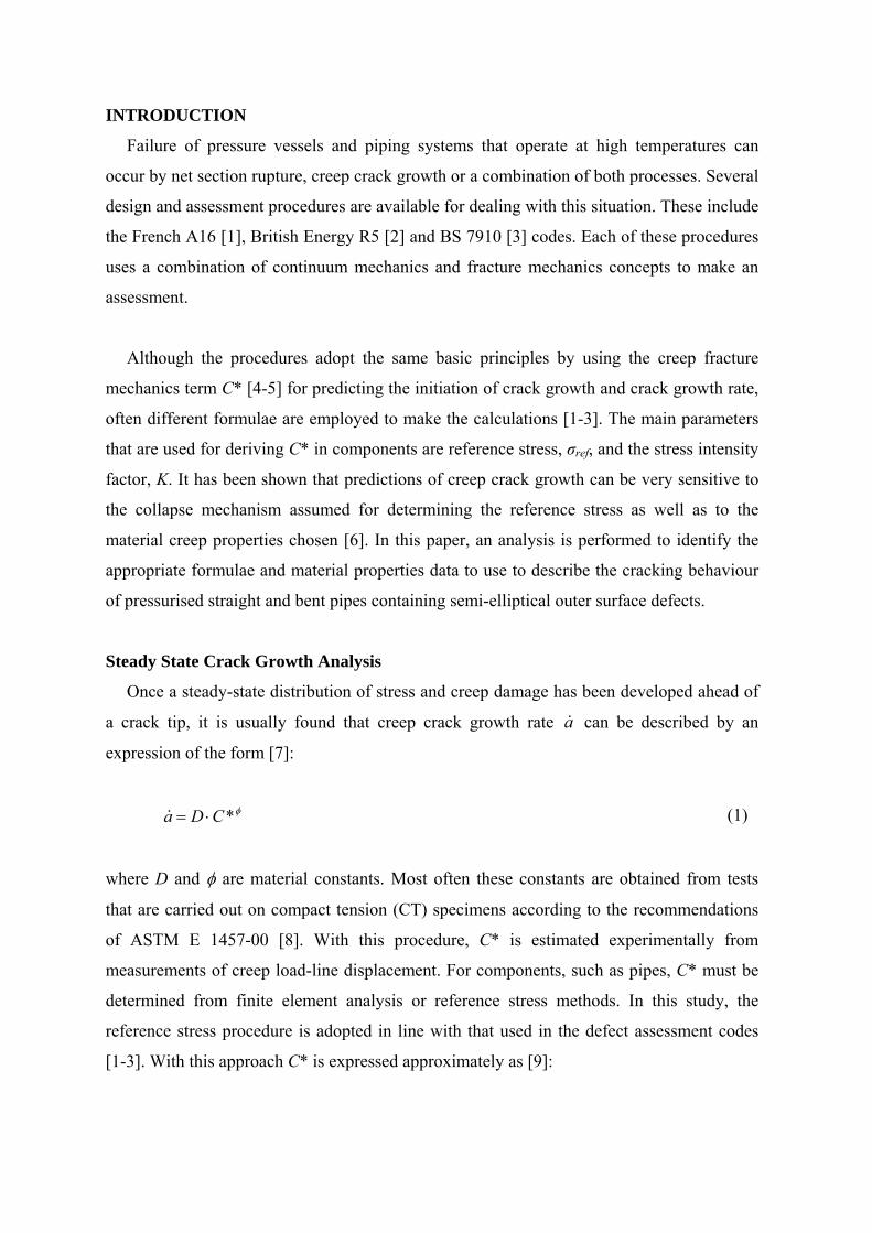
INTRODUCTION
Failure of pressure vessels and piping systems that operate at high temperatures can
occur by net section rupture, creep crack growth or a combination of both processes. Several
design and assessment procedures are available for dealing with this situation. These include
the French A16 [1], British Energy R5 [2] and BS 7910 [3] codes. Each of these procedures
uses a combination of continuum mechanics and fracture mechanics concepts to make an
assessment.
Although the procedures adopt the same basic principles by using the creep fracture
mechanics term C* [4-5] for predicting the initiation of crack growth and crack growth rate,
often different formulae are employed to make the calculations [1-3]. The main parameters
that are used for deriving C* in components are reference stress, σref, and the stress intensity
factor, K. It has been shown that predictions of creep crack growth can be very sensitive to
the collapse mechanism assumed for determining the reference stress as well as to the
material creep properties chosen [6]. In this paper, an analysis is performed to identify the
appropriate formulae and material properties data to use to describe the cracking behaviour
of pressurised straight and bent pipes containing semi-elliptical outer surface defects.
Steady State Crack Growth Analysis
Once a steady-state distribution of stress and creep damage has been developed ahead of
a crack tip, it is usually found that creep crack growth rate a can be described by an
expression of the form [7]:
φ*CDa ⋅= (1)
where D and φ are material constants. Most often these constants are obtained from tests
that are carried out on compact tension (CT) specimens according to the recommendations
of ASTM E 1457-00 [8]. With this procedure, C* is estimated experimentally from
measurements of creep load-line displacement. For components, such as pipes, C* must be
determined from finite element analysis or reference stress methods. In this study, the
reference stress procedure is adopted in line with that used in the defect assessment codes
[1-3]. With this approach C* is expressed approximately as [9]:

2
⎟⎟⎠
⎞⎜⎜⎝
⎛⋅⋅=
refrefref
*ref
KCσ
εσ (2)
where ε ˙ref is the creep strain rate at the appropriate σref for the component and K is the stress
intensity factor corresponding to the applied loading. When the creep strain rate ε ˙ at an
applied stress σ can be described in terms of the Norton creep law [10]:
nA σε ⋅= (3)
where A and n are material constants at constant temperature, Eq. (2) can be rewritten as:
21 KAC nref
*ref ⋅⋅= −σ (4)
This equation will be used in the subsequent analysis to compare the cracking behaviour
of the pipes with the materials properties data obtained from compact tension specimens.
Crack Initiation Analysis
When a structure containing a defect is first loaded the stress distribution is given by the
elastic K-field or the elastic-plastic J-field. Therefore, time is required for the stresses to
redistribute to the steady-state creep stress distribution controlled by C*. During this period,
transient conditions exist which are not uniquely defined by C*. In addition, a time is
needed for creep damage to develop around the crack tip [11]. Furthermore due to the
practical limitations of crack detection equipment, the initiation of crack growth is difficult
to determine precisely. Typically, this ranges between an extension Δa of between about 0.1
and 0.5 mm depending on component and crack dimensions. ASTM E 1457-00 [8]
identifies an extension of 0.2 mm for tests on CT specimens to cover the entire transition
time to steady state conditions. This distance also takes into account the resolution of crack
monitoring equipment. In this present work, it has been determined that Δa = 0.5 mm is a
suitable value to choose for semi-elliptical defects in pipes.
From Eq. (1) it may be expected that the time, ti, to initiate a crack extension of Δa can
be expressed by:

iC
Dt ii φ*= (5)
where Di and φi are material constants. For steady state cracking Di is expected to be given
approximately by Δa/D with φ =φi. This equation assumes that the entire initiation period is
governed by steady state value of C*. This cannot be expected to be true during at least part
of the initiation period ti. The applicability of the equation will be examined for the pipes.
Reference Stress Solutions
It has been shown previously that although different codes employ Eq. (2), often different
formulae are used to evaluate K and σref [6]. Greater sensitivity of C* and cracking rate to
reference stress than to K is expected from Eq. (4) since φ in Eq. (1) is close to one, and
typically n >> 1. This has been demonstrated previously [6]. In the present work, solutions
for K due to Raju and Newman [12] have been used throughout: those for reference stress
have been taken from R6 and are defined as σref R6 Global [13-14] and σref R6 Local [15] to
correspond with estimates that are based on ‘global’ and ‘local’ collapse, respectively. The
same reference stress solutions have been used for the straight and bent pipes since it has
been shown [16] that defects at the extrados or crown are not affected by the bend curvature
and hence the bend may be treated as a straight cylinder.
‘Global’ solution
‘Global’ solutions of reference stress are based on collapse of the entire cross-section at
the site of a defect. For a semi-elliptical axial outer surface defect in a pipe subjected to an
internal pressure p, R6 gives [13-14]:
( ) ⎟⎟
⎠
⎞⎜⎜⎝
⎛ −+⋅
−
=
i
e
e
GlobalRref
RaRcabate
aR
p
ln,16 σ (6)
where bate(a, c) is:

( )[ ]aaRc
acabate
e ⋅−⋅+
=2
61.11
),( (7)
In these equations, is crack depth, c is half crack length at the surface and Ra i and Re are
the internal and external radii of the pipe, respectively.
‘ Local’ solution
R6 uses a formula for ‘local’ collapse [15] of the ligament ahead of a crack based on
Sattari-Far [17] to give:
( ) ( ) ( )
( )2
222
2
6 1
193
ζ
σζσ
ζσ
ζσ
−
⋅−+⋅+⋅=
mbb
Localref R
gg (8)
where
( )75.0
3
2201 ⎟
⎠⎞
⎜⎝⎛⋅⋅−=
cag ζζ (9)
( )WcWca⋅+⋅
⋅=
222
ζ
(10)
In these equations, W is pipe wall thickness and σb and σm are the linearised bending and
membrane stresses across the crack plane as defined in BS 7910 [3].
Experiments
The 9% Cr-steel examined was designated P91. Its chemical composition is shown in
Table 1. All the pipe and compact tension specimens were taken from the same batch of
steel. The study formed part of a European Union collaborative programme called ‘HIDA’
[7,18-19]. A total of 2 straight and 2 bent pipes was examined and all testing was carried out
at 625°C. Basic creep crack growth data were obtained on standard compact tension
specimens with a thickness B = 25 mm containing 20% deep side-grooves on each side. The
tests were performed at different laboratories using the same procedures. For the CT tests,
the technique recommended in ASTM E 1457-00 [8] was adopted.
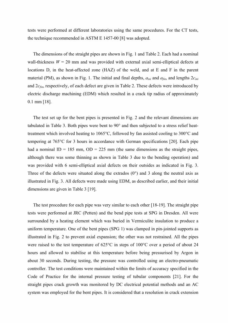
The dimensions of the straight pipes are shown in Fig. 1 and Table 2. Each had a nominal
wall-thickness W = 20 mm and was provided with external axial semi-elliptical defects at
locations D, in the heat-affected zone (HAZ) of the weld, and at E and F in the parent
material (PM), as shown in Fig. 1. The initial and final depths, aini and afin, and lengths 2cini
and 2cfin, respectively, of each defect are given in Table 2. These defects were introduced by
electric discharge machining (EDM) which resulted in a crack tip radius of approximately
0.1 mm [18].
The test set up for the bent pipes is presented in Fig. 2 and the relevant dimensions are
tabulated in Table 3. Both pipes were bent to 90° and then subjected to a stress relief heat-
treatment which involved heating to 1065°C, followed by fan assisted cooling to 300°C and
tempering at 765°C for 3 hours in accordance with German specifications [20]. Each pipe
had a nominal ID = 185 mm, OD = 225 mm (the same dimensions as the straight pipes,
although there was some thinning as shown in Table 3 due to the bending operation) and
was provided with 6 semi-elliptical axial defects on their outsides as indicated in Fig. 3.
Three of the defects were situated along the extrados (0°) and 3 along the neutral axis as
illustrated in Fig. 3. All defects were made using EDM, as described earlier, and their initial
dimensions are given in Table 3 [19].
The test procedure for each pipe was very similar to each other [18-19]. The straight pipe
tests were performed at JRC (Petten) and the bend pipe tests at SPG in Dresden. All were
surrounded by a heating element which was buried in Vermiculite insulation to produce a
uniform temperature. One of the bent pipes (SPG 1) was clamped in pin-jointed supports as
illustrated in Fig. 2 to prevent axial expansion; the other was not restrained. All the pipes
were raised to the test temperature of 625°C in steps of 100°C over a period of about 24
hours and allowed to stabilise at this temperature before being pressurised by Argon in
about 30 seconds. During testing, the pressure was controlled using an electro-pneumatic
controller. The test conditions were maintained within the limits of accuracy specified in the
Code of Practice for the internal pressure testing of tubular components [21]. For the
straight pipes crack growth was monitored by DC electrical potential methods and an AC
system was employed for the bent pipes. It is considered that a resolution in crack extension

between about 0.2 to 0.5 mm could be achieved with these techniques depending on the
crack growth rate being monitored.
The loading conditions applied to each pipe are summarised in Table 4. Pipes ERA 1 and
SPG 1 were subjected to a constant internal pressure although this pressure was increased
after 1240 hours of testing for pipe SPG 1 since no change in potential was detectable. For
pipes ERA 2 and SPG 2, the pressure was cycled between 0 and its maximum value at a
frequency of 10-4 Hz (such that the maximum pressure was maintained for 9960 seconds for
each cycle) except that no cycling was incurred between 1550 and 1990 hours for pipe ERA
2. The pipe tests were stopped either after a leak was detected or sufficient crack extension
had taken place. For the straight pipes, the tests were interrupted after defect D, in the HAZ,
had propagated through the wall. Both bent pipe tests were stopped prior to leakage.
Experimental Results
For the straight pipes, most crack growth occurred in the HAZ (defect D). The amount of
crack extension that took place at defect E in the parent material is shown in Figs. 4 and 5.
This only amounted to about 0.8 mm in both cases. On the other hand, there was no growth
from defect F in either pipe. The results for defect D are not included since in this paper the
intention is only to interpret cracking in the parent material. From Table 2, it can be seen
that defects D and E had approximately the same initial size and defect F was the smallest. It
is evident, therefore, from Figs. 4 and 5 that the HAZ material is more susceptible to
cracking than the parent material and it is not surprising that no growth occurred from defect
F. These figures clearly show the resolution in crack extension achievable with the crack
monitoring system used. It is considered that an extension of Δa = 0.5 mm can be detected
reliably [22]. The data were smoothed for subsequent analysis.
The experimental results for crack growth in the bent pipes are presented in Figs. 6 and 7.
These figures indicate that the greatest amount of cracking occurred from the largest defect
at the extrados (defect Y) followed by the same size of defect at the neutral axis (defect Q).
This observation implies some influence from the bending operation, although it would
seem that there is little effect of the method of end fixing at the supports. It is apparent that
little crack growth occurred from the other defects except for defect Z at the extrados of pipe
SPG 2. No data were available for this defect in pipe SPG1. It should be noted that the crack
extension for defects Z and Q are approximately the same, as shown in Fig. 7, even though

the initial defect in Z was nearly half of that of Q. This may suggest the importance of
defect position for the present pipe bends.
For both straight and bent pipe tests, there is no obvious influence of cycling of pressure
on the cracking rates measured (Figs. 4-7). This is mainly due to the low frequency dwell
times of 10-4 Hz used. Furthermore, in all cases the fracture surfaces were seen to be
predominantly intergranular [19, 22] suggesting pre-dominance of time-dependant cracking
behaviour in the cyclic tests.
The data obtained from the compact tension tests are presented in Fig. 8. This figure
shows creep crack growth rate a ˙ plotted against C* where C* has been determined
experimentally from measured creep displacement rates in accordance with the procedure
given in ASTM E 1457-00 [8]. It is evident that the results can be expressed in the form of
Eq. (1) with the values of D and φ given Table 5. The figure includes data that were
obtained under static loading and cyclic loading at a frequency equal to or less than 10-2 Hz.
It is apparent that both the static and cyclic loading results can be accommodated within the
same scatter band of plus or minus two standard deviations indicating little influence of
fatigue on the cracking process at frequencies of 10-2 Hz or less. Also in both cases the
fracture surfaces were mainly intergranular.
Crack growth analysis
In a previous study [6], it has been demonstrated that predictions of creep crack growth
are sensitive to the uniaxial creep material properties and formulae used for calculating
reference stress in Eqs. (2) and (4). Based on this study, values of A and n, which are given
in Table 6, have been taken from measured minimum strain rates, ε ˙min, , to calculate C*.
Figure 9 compares predictions of the cracking behaviour of defect Y in bent pipe SPG 1,
derived from different estimates of reference stress, with the CT scatter band. Also, Eqs. (6)
and (8) have been employed in conjunction with both nominal wall thickness and local wall
thickness (see Table 3) due to the thinning that occurred during the bending operation. It is
evident from Fig. 9 that estimates of C* determined from reference stresses based on a
‘local’ collapse mechanism and the thinnest wall thicknesses result in the largest C* values
and greatest deviation from the CT data band. In contrast, the use of nominal wall thickness
combined with a ‘global’ estimate of reference stress gives the closest agreement.

In Figure 10, comparisons of crack growth rates for most of the defects in the pipes using
nominal wall thickness and ‘global’ estimates of reference stress in the C* expression (Eqs.
(2) and (4)) are made with CT data. It is evident that broad agreement is achieved. This
demonstrates that it is more appropriate to base C* on ‘global’ estimates of reference stress
for semi-elliptical defects in pipes. Also, no distinction is observed between the straight and
bent pipe data and also between the static and cyclic crack growth results.
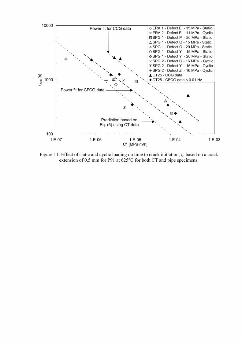
Crack initiation data for the pipes assuming a crack extension of Δa = 0.5 mm are
illustrated in Fig. 11. It is obvious that the time to reach this amount to cracking is less under
cycling loading than under static loading conditions suggesting that cyclic loading
accelerates the approach to steady state conditions. In addition, it is apparent that
substitution of D and φ from Table 5 into Eq. (5) for Di and φi, for a crack extension of Δa =
0.5 mm, assuming steady state conditions, under predicts incubation times in Fig. 11. This is
to be expected whilst damage is building up at a crack tip during the early stage of cracking
[23].
CONCLUSIONS
Data on creep crack growth from external semi elliptical defects in pressurised straight
and bent pipes of a 9% Cr-steel at 625°C have been reported. The results have been plotted
in terms of the creep fracture mechanics parameter C*. It has been shown that estimates of
C* are sensitive to the formula used for calculating reference stress, the material properties
chosen and the dimensions assumed for the pipe wall thickness. It has been found that good
agreement is obtained with compact tension specimen data when comparisons are made
with ‘global’ estimates of reference stress using nominal pipe wall thickness and with C*
calculated from minimum creep strain rate uniaxial data.
Tests performed on straight and bent pipes have shown the same behaviour. Little
difference in crack growth rate has been observed in pipe and compact tension results for
experiments carried out under static and slow cyclic pressure loading. In all cases
predominantly intergranular fracture surfaces were observed suggesting a creep dominated
cracking mode. However, crack initiation was found to occur earlier when pressure was
cycled than when it was held constant suggesting that cycling speeds the approach to steady

state conditions. Furthermore predictions derived from Eq. (5), assuming steady state
conditions, give shorter times to an initial crack extension of Δa = 0.5 mm compared to the
experimental data.
ACKNOLEDMENTS
The authors would like to acknowledge the provision of data from the EU Brite/Euram
‘HIDA’ (1996-2000) project partners and the financial support from the European
Community and British Energy Generation Ltd.
REFERENCES
1. Commissariat à l’Energie Atomique. A16: Guide for Defect Assessment and Leak
Before Break Analysis, 4th ed. Saclay: CEA, 2002.
2. Ainsworth, R. A. Editor R5: Assessment Procedure for the High Temperature
Response of Structures, Nuclear Electric procedure R5 Issue2, 1999.
3. British Standard. BS 7910: Guide on Methods for Assessing the Acceptability of
Flaws in Metallic Structures, BSI, 1999.
4. Landes, J. D. and Begley, J. A. A Fracture Mechanics Approach to Creep Crack
Growth, ASTM STP 590, pp: 128-148, 1976.
5. Nikbin, K. M., Webster, G. A. and Turner, C. E. Relevance of Non-Linear Fracture
Mechanics to Creep Cracking, Cracks and Fracture, ASTM STP 601, Pittsburgh, pp:
47-62, 1976.
6. Wasmer, K., Nikbin, K. M. and Webster, G. A. A Sensitivity Study of Creep Crack
Growth in Pipes; PVP Vol 438, New and Emerging Computational Methods:
Applications to Fracture, Damage and Reliability, pp: 17-24, ASME, New York,
2002.
7. Tan, M., Celard, N. J. C., Nikbin, K. M. and Webster, G. A., Comparison of Creep
Crack Initiation and Growth in Four Steels tested in HIDA, Int Jnl of Pressure Vessels
and Piping 2001; 78(11-12): 737 – 747.
8. ASTM. “ASTM E 1457-00: Standard Test Method for Measurement of Creep Crack
Growth Rates in Metals”, Annual Book of ASTM Standards, Vol 3, n° 1, pp: 936-
950, 2001.
9. Ainsworth, R.A. Some Observations on Creep Crack Growth, Int Jnl of Fracture
1982; 20: 147-159.
10. Norton, F.H. The Creep of Steel at High Temperatures. Edited by McGraw and Hill.

London, 1929.
11. Nikbin, K. M. Transition Effects in Creep-Brittle Materials, Mechanics of Creep
Brittle Materials II’, Eds A. C. F. Cocks, A.R.S. Ponter, Elsevier applied Science, pp:
14-24, 1991.
12. Raju, I. S. and Newman, J. C. Stress-Intensity Factors for Internal and External
Surface Cracks in Cylindrical Vessels, Jnl of Pressure Vessel Technology 1982; 104:
293-298.
13. British Energy Generation Ltd. “R6: Assessment of the Integrity of Structures
Containing Defects”. British Energy Generation Ltd 1996. UK, Report R6, version
1.4, Appendix M7-6, pp: M7-3-5.
14. Connors, D. C. A Compendium of Limit Loads, British Energy Generation Ltd 1996.
Uk, Report M/TE/GEN/REP/0054/98.
15. British Energy Generation Ltd. R6: Assessment of the Integrity of Structures
Containing Defects. British Energy Generation Ltd 2001. UK, Report R6, revision 4,
Appendix IV.1.12.4, pp: IV.1.35.
16. Miller, A.G. Review of Limit Loads of Structures Containing Defects. Int Jnl of
Pressure Vessels and Piping 1988; 32(2): 197-327.
17. Sattari-Far, I. Finite Element Analysis of Limit Loads for Surface Cracks in Plate, Int
Jnl of Pressure Vessels and Piping 1994; 57(2): 237-243.
18. Le Mat Hamata, N. and Shibli, I. A. Creep Crack Growth of Seam-Welded P22 and
P91 Pipes with Artificial Defects. Part I: Experimental Study and Post-Test
Metallography, Int Jnl of Pressure Vessels and Piping 2001; 78 (11-12): 819-826.
19. Gampe, U. and Seliger, P. Creep Crack Growth Testing of P91 and P22 Pipes Bends,
Int Jnl of Pressure Vessels and Piping 2001; 78 (11-12): 859-864.
20. VdTÜV-Werstoffblatt 511/2. Warmfester Stahl X10CrMoVNb 9-1, Ausgabe
(09.1995).
21. “A Code of Practice for Internal Pressure Testing of Tubular Components at Elevated
Temperatures”, High Temperature Mechanical Testing Committee, October 1989.
22. Le Mat Hamata, N. and Shibli, I. A. Creep Crack Growth of Seam-Welded P22 and
P91 Pipes with Artificial Defects. Part II: Data Analysis. Int Jnl of Pressure Vessels
and Piping 2001; 78(11-12): 827-835.
23. Webster, G. A. and Ainsworth, R.A. High Temperature Components Life
Assessment, Chapman & Hall, London, 1994.

Figure 1: Geometry of the straight ‘ERA’ pipe showing location of external defects
Figure 2: Bent pipe coordinate system with pined supported used for pipe SPG1
Figure 3: Geometry of defect positions in bent pipes SPG1 and SPG2. The details of the defects are
given in Table 3

7.8
8.0
8.2
8.4
8.6
8.8
9.0
0 200 400 600 800 1000 1200 1400 1600Time [h]
a [m
m]
ERA 1 - Defect E (PM) - Experimental Data
ERA 1 - Defect E (PM) - Smoothed Data
Figure 4: Creep crack growth for defect E in ERA1 pipe at 625°C showing the scatter in
crack length measurements
7.0
7.5
8.0
8.5
9.0
9.5
10.0
0 1000 2000 3000 4000 5000 6Time [h]
a [m
m]
000
ERA 2 - Defect E (PM) - Experimental Data
ERA 2 - Defect E (PM) - Smoothed Data
Figure 5: Creep crack growth for defect E in ERA2 pipe at 625°C showing a large scatter
in the analysis of the results

-2
0
2
4
6
8
0 500 1000 1500 2000 2500 3000Time [h]
Δa
[mm
]Defect P
Defect Q
Defect R
Defect X
Defect Y
15 MPa 20 MPa
Figure 6: Creep crack growth for all defects in SPG1, P91 bent pipe at 625°C showing a
pressure increase at the middle of the test
-1.0
-0.5
0.0
0.5
1.0
1.5
2.0
2.5
3.0
3.5
0 500 1000 1500 2000 2500 3000Time [h]
Δa [m
m]
Defect P
Defect Q
Defect R
Defect X
Defect Y
Defect Z
Figure 7: Creep crack growth extension for all defects in SPG2, P91 bent pipe at 625°C

1.0E-04
1.0E-03
1.0E-02
1.0E-01
1.0E+00
1.0E-07 1.0E-06 1.0E-05 1.0E-04 1.0E-03 1.0E-02C* [MPa·m/h]
da/d
t [m
m/h
]CT25 - CCG
CT25 - CFCG < 0.01 Hz
Mean + 2 SD
Mean
Mean - 2 SD
Figure 8: Comparison of static and slow cycle creep crack growth for P91 – PM – CT specimens
at 625°C
1.0E-04
1.0E-03
1.0E-02
1.0E-01
1.0E+00
1.0E-07 1.0E-06 1.0E-05 1.0E-04 1.0E-03 1.0E-02 1.0E-01C* [MPa·m/h]
da/d
t [m
m/h
]
15 MPa - R6 Global - W = 20 mm20 MPa - R6 Global - W = 20 mm15 MPa - R6 Global - W = 16 mm20 MPa - R6 Global - W = 16 mm15 MPa - R6 Local - W = 20 mm20 MPa - R6 Local - W = 20 mm15 MPa - R6 Local - W = 16 mm20 MPa - R6 Local - W = 16 mm P91 - PM - CT - Experimental Data
Mean + 2 SD
Mean
Mean - 2 SD
Figure 9: Comparison of cracking rates based on ‘global’ and ‘local’ σref solutions for defect
Y in bent pipe SPG1 using nominal and local thickness measurements at two different pressures

Figure 10: Comparison of creep crack growth rate for the pipe tests with the CT scatter
band versus C*, using global σref and nominal thickness, for P91 pipes at 625°C, showing no difference due to cyclic loading and loading history
100
1000
10000
1.E-07 1.E-06 1.E-05 1.E-04 1.E-03C* [MPa·m/h]
t i500
[h]
ERA 1 - Defect E - 15 MPa - StaticERA 2 - Defect E - 11 MPa - CyclicSPG 1 - Defect P - 20 MPa - StaticSPG 1 - Defect Q - 15 MPa - StaticSPG 1 - Defect Q - 20 MPa - StaticSPG 1 - Defect Y - 15 MPa - StaticSPG 1 - Defect Y - 20 MPa - StaticSPG 2 - Defect Q - 16 MPa - CyclicSPG 2 - Defect Y - 16 MPa - CyclicSPG 2 - Defect Z - 16 MPa - CyclicCT25 - CCG dataCT25 - CFCG data < 0.01 Hz
Prediction based on Eq. (5) using CT data
Power fit for CFCG data
Power fit for CCG data
Figure 11: Effect of static and cyclic loading on time to crack initiation, ti, based on a crack
extension of 0.5 mm for P91 at 625°C for both CT and pipe specimens.

Figure 1: Geometry of the straight ‘ERA’ pipe showing location of defects
Figure 2: Bent pipe coordinate system
Figure 3: Geometry of defect positions in bent pipes SPG1 and SPG2. The details of the
defects are given in Table 3
Figure 4: Creep crack growth for defect E in ERA1 pipe at 625°C showing the scatter in
crack length measurements
Figure 5: Creep crack growth for defect E in ERA2 pipe at 625°C showing a large scatter in
the analysis of the results
Figure 6: Creep crack growth for all defects in SPG1 bent pipe at 625°C showing a pressure
increase at the middle of the test
Figure 7: Creep crack growth extension for all defects in SPG2, P91 bent pipe at 625°C
Figure 8: Comparison of static and slow cycle creep crack growth for P91 – PM – CT
specimens at 625°C
Figure 9: Comparison of cracking rates based on ‘global’ and ‘local’ σref solutions for defect
Y in bent pipe SPG1 using nominal and local thickness measurements at two different
pressures
Figure 10: Comparison of creep crack growth rate for the pipe tests with the CT scatter band
versus C*, using global σref and nominal thickness, for P91 pipes at 625°C, showing no
difference due to cyclic loading and loading history
Figure 11: Effect of static and cyclic loading on time to crack initiation, ti, based on a crack
extension of 0.5 mm for P91 at 625°C for both CT and pipe specimens

Table 1: Chemical composition of P91 steel (Weight in %)
C Mn Si S P Cr Ni Mo V Cu N Al 0.091 0.409 0.369 0.013 0.028 8.440 0.270 0.920 0.240 0.040 0.038 0.070

Table 2: Dimensions of defects in straight pipes ERA1 and ERA2
Pipe Defect aini 2cini afin 2cini 2cfin aini/cini aini/W D (HAZ) 7.63 39.88 18.44 39.88 93.54 0.38 0.38 E (PM) 8.05 40.00 8.90 40.00 Not Given 0.40 0.40 ERA1 F (PM) 5.00 25.00 5.00 25.00 25.00 0.40 0.25
D (HAZ) 8.00 43.68 15.72 43.68 96.76 0.37 0.40 E (PM) 8.00 40.00 8.87 40.00 Not Given 0.40 0.40 ERA2 F (PM) 5.00 25.00 5.00 25.00 25.00 0.40 0.25
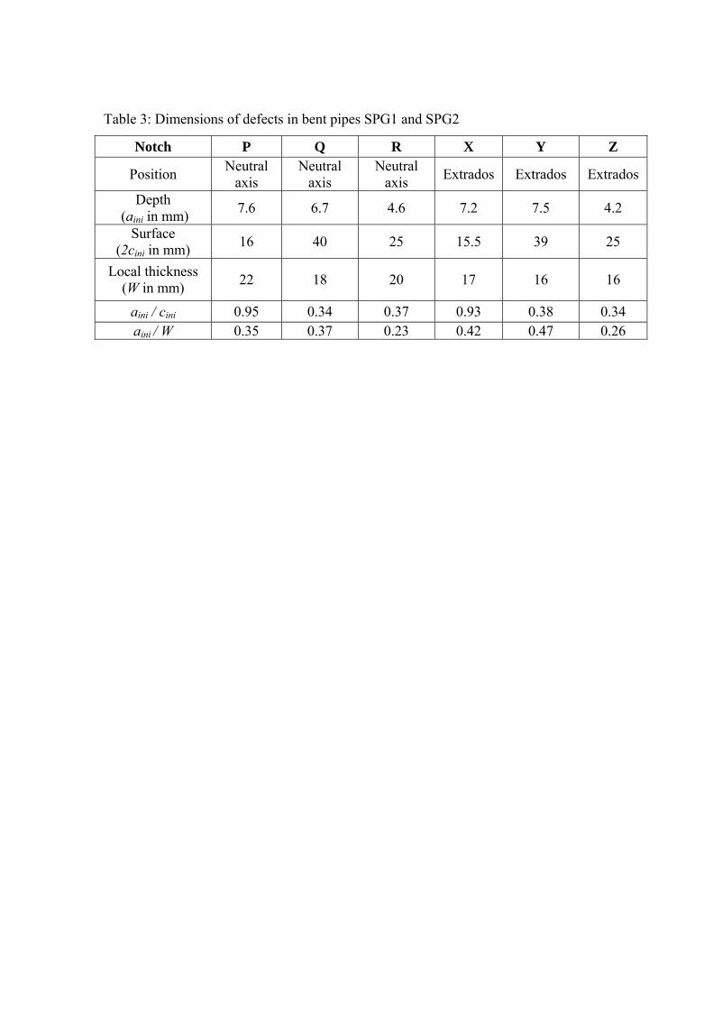
Table 3: Dimensions of defects in bent pipes SPG1 and SPG2
Notch P Q R X Y Z
Position Neutral axis
Neutral axis
Neutral axis Extrados Extrados Extrados
Depth (aini in mm) 7.6 6.7 4.6 7.2 7.5 4.2
Surface (2cini in mm) 16 40 25 15.5 39 25
Local thickness (W in mm) 22 18 20 17 16 16
aini / cini 0.95 0.34 0.37 0.93 0.38 0.34 aini
/ W 0.35 0.37 0.23 0.42 0.47 0.26
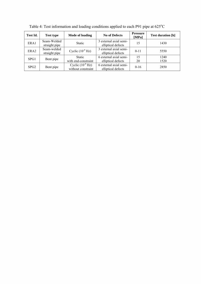
Table 4: Test information and loading conditions applied to each P91 pipe at 625oC
Test Id. Test type Mode of loading No of Defects Pressure [MPa] Test duration [h]
ERA1 Seam-Welded straight pipe Static 3 external axial semi-
elliptical defects 15 1430
ERA2 Seam-welded straight pipe Cyclic (10-4 Hz) 3 external axial semi-
elliptical defects 0-11 5550
SPG1 Bent pipe Static with end-constraint
6 external axial semi-elliptical defects
15 20
1240 1520
SPG2 Bent pipe Cyclic (10-4 Hz) without constraint
6 external axial semi-elliptical defects 0-16 2850

Table 5: Mean values of steady state creep crack growth parameters for P91 at 625oC obtained from CT specimen tests.
Material Condition D+ φ PM 1.44 0.60
+ Units correspond to cracking rate in mm/h with C* in MPa/h.

Table 6: Mean values of A and n (in Eq. (3)) obtained from uniaxial creep tests on P91 at 625ºC
Mat. Cond. Creep rate A+ n PM ε ˙min 1.38E-22 8.38
+ Units correspond to strain rate in 1/h with stress in MPa.


![Impact Initiation of Explosives and Propellants via Statistical Crack Mechanics [Sd]](https://static.fdocuments.in/doc/165x107/55cf9b45550346d033a561f9/impact-initiation-of-explosives-and-propellants-via-statistical-crack-mechanics.jpg)