
Article - ORC 2017 · Web viewMore recently, the ORC technology has been effectively applied in...
8
Available online at www.sciencedirect.com ScienceDirect Energy Procedia 00 (2017) 000–000 www.elsevier.com/locate/procedia IV International Seminar on ORC Power Systems, ORC2017 13-15 September 2017, Milano, Italy Large multistage axial turbines Roberto Bini a , Davide Colombo a , * a Turboden S.p.A., via Cernaia 10, 25124 Brescia, Italy Abstract 1. Though multistage axial turbines are being widely used since many decades for water steam expansion or in gas turbines, their use in ORCs has traditionally found limitations as a consequence of the choice of designing turbines with cantilever arrangements. 2. The choice of the cantilever arrangement is mainly related to the advantages of having simple shaft bearings design, only one rotating seal system in contact with the working fluid, a lighter and more compact turbine casing, only one side of the turbine casing occupied with the bearing and sealing systems (leaving the other side free to host the outlet duct for working fluid expanded vapour which often features very large volumetric flow rates), easiness of access for ordinary and extraordinary maintenance. Hence cantilever arrangement involves definitely lower turbine costs, both in terms of Capex and Opex and is practically the only solution adopted by the industrial suppliers of ORC turbines. 3. By adopting the cantilever arrangement the installation of several turbine discs hosting several expansion stages, traditionally installed one close to the other, would increase the overhang mass of the turbine rotor and decrease the natural frequencies of the system, yielding some mechanical problems and, at the end, limiting the possibility of installing, practically, more than 2-3 stages with this kind of arrangement. 4. On the other hand, however, modern ORC turbines require to increase number of stages to better exploit the expansion enthalpy drop, in order to increase turbine efficiency and/or to allow to adopt a low rotating speed (even 1,500 rpm) for a direct connection with synchronous generator. 5. The paper will describe an innovative solution that has allowed to increase the number of stages from the traditional 2-3 to at least 5 without leaving the effective cantilever arrangement, keeping the concept of ‘rigid’ rotor (i.e. operating below the first flexional natural frequency), with very low measured vibrations. 6. Operating data of a 9 MW 5 stage ORC turbine put in operation in 2016 will also be presented. © 2017 The Authors. Published by Elsevier Ltd. Peer-review under responsibility of the scientific committee of the IV International Seminar on ORC Power Systems. Keywords: ORC, ORC Turbine, multistage turbine, axial turbine, cantilever turbine * * Corresponding author. Tel.: +39 030 355 2001. E-mail address: [email protected] 1876-6102 © 2017 The Authors. Published by Elsevier Ltd. Peer-review under responsibility of the scientific committee of the IV International Seminar on ORC Power Systems.
-
Upload
nguyenxuyen -
Category
Documents
-
view
214 -
download
0
Transcript of Article - ORC 2017 · Web viewMore recently, the ORC technology has been effectively applied in...

Available online at www.sciencedirect.com
ScienceDirectEnergy Procedia 00 (2017) 000–000
www.elsevier.com/locate/procedia
IV International Seminar on ORC Power Systems, ORC201713-15 September 2017, Milano, Italy
Large multistage axial turbines
Roberto Binia, Davide Colomboa,*
aTurboden S.p.A., via Cernaia 10, 25124 Brescia, Italy
Abstract
1. Though multistage axial turbines are being widely used since many decades for water steam expansion or in gas turbines, their use in ORCs has traditionally found limitations as a consequence of the choice of designing turbines with cantilever arrangements.2. The choice of the cantilever arrangement is mainly related to the advantages of having simple shaft bearings design, only one rotating seal system in contact with the working fluid, a lighter and more compact turbine casing, only one side of the turbine casing occupied with the bearing and sealing systems (leaving the other side free to host the outlet duct for working fluid expanded vapour which often features very large volumetric flow rates), easiness of access for ordinary and extraordinary maintenance. Hence cantilever arrangement involves definitely lower turbine costs, both in terms of Capex and Opex and is practically the only solution adopted by the industrial suppliers of ORC turbines.3. By adopting the cantilever arrangement the installation of several turbine discs hosting several expansion stages, traditionally installed one close to the other, would increase the overhang mass of the turbine rotor and decrease the natural frequencies of the system, yielding some mechanical problems and, at the end, limiting the possibility of installing, practically, more than 2-3 stages with this kind of arrangement.4. On the other hand, however, modern ORC turbines require to increase number of stages to better exploit the expansion enthalpy drop, in order to increase turbine efficiency and/or to allow to adopt a low rotating speed (even 1,500 rpm) for a direct connection with synchronous generator.5. The paper will describe an innovative solution that has allowed to increase the number of stages from the traditional 2-3 to at least 5 without leaving the effective cantilever arrangement, keeping the concept of ‘rigid’ rotor (i.e. operating below the first flexional natural frequency), with very low measured vibrations.6. Operating data of a 9 MW 5 stage ORC turbine put in operation in 2016 will also be presented.
© 2017 The Authors. Published by Elsevier Ltd.Peer-review under responsibility of the scientific committee of the IV International Seminar on ORC Power Systems.
Keywords: ORC, ORC Turbine, multistage turbine, axial turbine, cantilever turbine
* * Corresponding author. Tel.: +39 030 355 2001.E-mail address: [email protected]
1876-6102 © 2017 The Authors. Published by Elsevier Ltd.Peer-review under responsibility of the scientific committee of the IV International Seminar on ORC Power Systems.

2 Roberto Bini, Davide Colombo / Energy Procedia 00 (2017) 000–000
1. Introduction
Traditionally, large ORC turbines, in which the rated output is typically exceeding 5MW, have been developed and mainly applied in Geothermal ORC applications where simplicity and long-term reliability have been the typical turbo-expander design drivers rather than the research of a remarkably high turbine efficiency at any cost.
Stating this situation, it is known that a typical ORC axial turbine for a geothermal application with organic fluid evaporation temperature in the range of 150°C is normally equipped with 2, 3 or, more rarely, 4 expansion stages. Most of the times these turbine are impulse type, with an average mean diameter in the range of 1 to 1.5 meters and a nominal speed of 1,500/1,800 rpm suitable for a four poles electric generator direct drive.
Such a design, due to the limited rotating mass, is typically arranged in a cantilever way, having the turbine shaft supported on one side and the rotating wheels attached on the other side, with evident advantages in terms of cost, serviceability, discharge flow arrangement, single rotating seal, turbine casing design and so on.
More recently, the ORC technology has been effectively applied in different applications such as industrial heat recovery, internal combustion engine and gas turbine heat recovery, solar, biomass and others.
In this kind of applications, the size of the ORC cycle approaches the size of geothermal ORCs but the temperature of the heat source is often higher than the typical temperature of a geothermal source and thus the enthalpy drop across the expander, which is a function of the thermodynamic cycle temperatures, is generally 2 to 5 times higher than what it is found in geothermal ORC, depending on the actual case.
As an example, a geothermal ORC in which Isopentane is utilized as process fluid having an evaporation temperature of 130°C, no superheating and a condensation temperature of 40°C will show across the turbine an isentropic enthalpy drop of 81.5 kJ whereas a heat recovery ORC with Cyclopentane as process fluid, evaporation at 220°C , a superheating of 100°C and the same condensing temperature will show some 230 kJ enthalpy drop.
Clearly in the second scenario, the use of a 2 or 3 stages axial expander can adversely affect the efficiency, even when a higher revolution speed is adopted (i.e. 3,000 rpm unit if required in conjunction with a speed reduction gear), due to the possible enthalpy drop overload of each stage and the largely supersonic flow within the turbine blading. In this case, a design with a larger number of stages could result in a better efficiency of the expander.
On the other hand, a cantilever design with more than 4 stages can be problematic, for a number of reasons that will be explained; a more complicated and, in turn, more expensive design with double side shaft support and split casing may be considered the only practical solution, with a significant adverse effect in the ORC application profitability.
2. Engineering of a cantilever 5 stage ORC axial expander
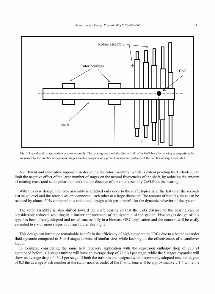
Normally, in a cantilever axial flow turbine, each subsequent expansion stage is attached to the shaft after the previous one and so not only the rotating mass is increased but also its Center of Gravity (CoG) becomes further and further distant from the shaft bearings and the polar moment of inertia is increasing as well. See Fig. 1.
Such a trend results in a progressive reduction of the flexional and torsional frequencies of the shaft with the evident and well known risk of system resonance with high vibration operation and, possibly, mechanical failures.
Even with proper selection of the bearings, whether they are oil film type or roller, and shaft diameter, which indeed plays a crucial role in the design, it is really difficult (or even impossible) to shift the natural frequency of the system safely above the rotational frequency and keep the concept of a ‘rigid’ rotor (i.e. with rotating speed below the first flexional natural frequency of the rotor).
This situation represents the most common obstacle in increasing the number of expansion stages in a cantilever turbine for ORC applications with a mean diameter in the range of 1.0 to 1.5 meters and a rotational speed of 1,500 to 3,000 rpm which is typically the case of 5 to 10MW high temperature ORC and consequentially represent a serious limitation in the efficiency of the expander in such kind of applications.
Author name / Energy Procedia 00 (2017) 000–000 3
Fig. 1 Typical multi stage cantilever rotor assembly. The rotating mass and the distance “d” of its CoG from the bearing is proportionally increased by the number of expansion stages. Such a design is very prone to resonance problems if the number of stages exceeds 4.
A different and innovative approach in designing the rotor assembly, which is patent pending by Turboden, can limit the negative effect of the large number of stages on the natural frequencies of the shaft, by reducing the amount of rotating mass (and so its polar moment) and the distance of the rotor assembly CoG from the bearing.
With this new design, the rotor assembly is attached only once to the shaft, typically at the last or at the second-last stage level and the rotor discs are connected each other at a large diameter. The amount of rotating mass can be reduced by almost 50% compared to a traditional design with great benefit for the dynamic behavior of the system.
The rotor assembly is also shifted toward the shaft bearing so that the CoG distance to the bearing can be considerably reduced, resulting in a further enhancement of the dynamic of the system. Five stages design of this type has been already adopted and tested successfully in a biomass ORC application and the concept will be easily extended to six or more stages in a near future. See Fig. 2.
This design can introduce remarkable benefit in the efficiency of high temperature ORCs due to a better expander fluid dynamic compared to 3 or 4 stages turbine of similar size, while keeping all the effectiveness of a cantilever layout.
In example, considering the same heat recovery application with the expansion enthalpy drop of 230 kJ mentioned before, a 3 stages turbine will have an average drop of 76.6 kJ per stage, while the 5 stages expander will show an average drop of 46 kJ per stage. If both the turbines are designed with a commonly adopted reaction degree of 0.3 the average Mach number at the stator nozzles outlet of the first turbine will be approximatively 1.4 while the
d
CoG
Rotors assembly
Shaft
Rotor bearings

4 Roberto Bini, Davide Colombo / Energy Procedia 00 (2017) 000–000
second turbine will have a Mach number around 1 which evidently represents a benefit in terms of expansion efficiency.
Also the rotor cascades will show reduced profile losses due to the lower angular deflection required and the less aggressive volumetric expansion ratios.
The new design appears particularly attractive also in terms of Capex since it is relying on the same manufacturing technology as the previous design. Off course, any additional expansion stage introduces its own cost (disc, rings, blades, seals, etc.) but this happens with practical no impact on the cost of the turbine casing and of the spindle assembly.
This technology recently received the Mitsubishi Heavy Industry (MHI) “Best Innovations Award 2016”, a Corporate level competition aimed to develop valuable technology within the MHI group.
Fig. 2 Turboden patented design. The rotating mass and the distance “d” of its CoG from the bearing remains under control while increasing the number of expansion stages. Such a design is safe in relations to resonance problems even when the number of stages exceeds 4.
3. A 9MW five stages high temperature example
The first unit of a series of turbines adopting this new rotor design is installed on a 9MW biomass fired ORC plant in operation since 2016 in the USA.
The actual Campbell diagram of this high temperature turbine (5 stages with nominal speed of 3,000 rpm) is presented in Fig. 3. It can be observed the evident margin against resonance: not only the turbine is normally operated below the first natural frequency but also at 20% overspeed (3,600 rpm) the unit is far from resonance. For
CoG
Rotors assembly
Shaft
Rotor bearings
d

Author name / Energy Procedia 00 (2017) 000–000 5
comparison, Fig. 4 shows the Campbell diagram of the same 5 stages turbine if the previous design was adopted: resonance occurs around the nominal speed of 3000 rpm which is considered a weak and unsafe design.
Fig. 3 Campbell diagram of a 5 stages 9MW turbine adopting the new design.Resonance occurs well above 3600 rpm while the nominal operation speed is 3000 rpm.
Fig. 4 Campbell diagram of a 5 stages 9MW turbine adopting the traditional design.Resonance occurs around the nominal speed of 3000 rpm.

6 Roberto Bini, Davide Colombo / Energy Procedia 00 (2017) 000–000
This unit has been compared in terms of performance efficiency to a 6MW 3 stages unit in operation since 2012 expanding the same fluid at similar thermodynamic conditions. The two turbines share the same mean diameter and the same rotational speed while the blades height differs proportionally to the different power size of the turbines. The total to static efficiency has been calculated at a frequency of 5 minutes over a period of approximatively 2 months of normal operation and it is plotted versus the volumetric expansion ratio. See Fig. 5.
Fig. 5 Total to static efficiency vs. Volumetric expansion ratio of a 3 stages turbine (blue dots) and a 5 stages turbine (orange dots) expanding the same fluid. The black lines represents the average efficiency over the considered time period (2 month).
At comparable expansion ratios, the measured efficiency of the 5 stages turbine has been increased by more than 5 percentage points compared to the efficiency of the 3 stages expander.In Fig. 6 a picture of the five stages rotor assembly during machining is also presented.

Author name / Energy Procedia 00 (2017) 000–000 7
Fig. 6 Five stage rotor during machining.
4. Technology application to the geothermal ORCs
This technology can be effectively applied also to geothermal ORC expanders. Although geothermal sources are typically characterized by lower temperatures compared to heat recovery applications, by employing more than four stages it is sometimes possible to achieve a better fluid dynamic design of the turbine, especially when 1,500 rpm direct drive configuration is adopted. Turboden applied the innovative rotor design to a five stage 16MW axial turbine for a geothermal application with the same expected efficiency improvement of about 5 percentage points compared to similar size 4 stage solution. See Fig 7.
Fig. 7 Five stage 16MW geothermal turbine adopting the new Turboden rotor design.
5. Conclusion
Typical cantilever layout is a convenient and effective turbine design widely adopted in ORC powerplants, representing the vast majority of the installed unit worldwide.

8 Roberto Bini, Davide Colombo / Energy Procedia 00 (2017) 000–000
This kind of design was limiting the number of expansion stages to 3 or 4, mainly due to the rotor-dynamic stability of the system that is adversely affected by the overhung mass proportionally increased by the number of the stages.
Large sized heat recovery ORCs and possibly geothermal ORCs could benefit by a larger number of expansion stages in the turbine (i.e. 5 or 6), improving their efficiency.
The new Turboden rotor design overcomes this limitation, introducing to the market a new 5 stages axial expanders family targeting both the heat recovery and the high efficiency geothermal ORC market.
The first unit of this kind is operation since 2016 showing an efficiency improvement of 5 and more percentage points compared to similar size previous generation units.


![[ORC-xx] OracleJSP](https://static.fdocuments.in/doc/165x107/5419fce17bef0ade168b45df/orc-xx-oraclejsp.jpg)