Prel. Design Method ORC Centrif. Turbines - ASME ORC2013 155.pdf · Preliminary Design Method For...
32
Preliminary Design Method For Small Scale Centrifugal ORC Turbines ASME-ORC 2013, 2 nd Int. Seminar on ORC Power Systems Rotterdam, 7-8 October E. Casati 1,2 , S. Vitale 1 ,M. Pini 2 ,G. Persico 2 , & P. Colonna 1 1 Aerospace Dept., Delft University of Technology 2 Energy Dept., Politecnico di Milano E. Casati , S. Vitale , M. Pini , G. Persico , & P. Colonna Prel. Design Method μORC Centrif. Turbines 1 / 21
Transcript of Prel. Design Method ORC Centrif. Turbines - ASME ORC2013 155.pdf · Preliminary Design Method For...
Preliminary Design MethodFor Small ScaleCentrifugal ORC TurbinesASME-ORC 2013, 2nd Int. Seminar on ORC Power SystemsRotterdam, 7-8 October
E. Casati1,2, S. Vitale1,M. Pini2,G. Persico2, & P. Colonna11Aerospace Dept., Delft University of Technology2 Energy Dept., Politecnico di Milano
E. Casati , S. Vitale , M. Pini , G. Persico , & P. ColonnaPrel. Design Method µORC Centrif. Turbines 1 / 21

Outline
1 0. Introduction
2 1. ORC Turbine
3 2. The zTurbo code
4 3. Preliminary design of a 10 kWel ROT
E. Casati , S. Vitale , M. Pini , G. Persico , & P. ColonnaPrel. Design Method µORC Centrif. Turbines 1 / 21

IntroductionORC systems ⇒ important for decentralized powergeneration.
- Future development of micro-ORC turbogenerator (10-100kWel)
- WHR from truck engines, concentrated solar, domesticCHP, ...
The turbine represents the most critical component interms of efficiency, compactness, cost.
E. Casati , S. Vitale , M. Pini , G. Persico , & P. ColonnaPrel. Design Method µORC Centrif. Turbines 2 / 21

Outline
1 0. Introduction
2 1. ORC Turbine
3 2. The zTurbo code
4 3. Preliminary design of a 10 kWel ROT
E. Casati , S. Vitale , M. Pini , G. Persico , & P. ColonnaPrel. Design Method µORC Centrif. Turbines 2 / 21

ORC Turbine (1/2)
Use of ORC fluids:simple layout, compact and reliable turbine Nstg ↓, U ↓
complex aerodynamic design M ↑ ,(
Vout/Vin
)↑
Large compressibility effect → No similarity rules (Ds, ωs)
=⇒ non-conventional turbine architectures=⇒ reliable preliminary design 1D tool for ORC turbines
E. Casati , S. Vitale , M. Pini , G. Persico , & P. ColonnaPrel. Design Method µORC Centrif. Turbines 3 / 21

ORC Turbine (2/2)
Centrifugal Architecture- D ↑ ⇒ Aflow ↑- “Easy” and compact multi-stage solutions- centrifugal term!!
Leu =V 2
1 −V 22
2 +W 2
2 −W 21
2 +U2
1−U22
2
ORC application Macchi (1977); Casci (1979):- stator-rotor solution, not counter-rotating
(1 generator)
3
2
1
STATORand CASE
(THRUST BALANCING)
ROTOR
VAPOR INLET
VAPOR INLET
VAPOR OUTLET
2
1
3
E. Casati , S. Vitale , M. Pini , G. Persico , & P. ColonnaPrel. Design Method µORC Centrif. Turbines 4 / 21

Outline
1 0. Introduction
2 1. ORC Turbine
3 2. The zTurbo code
4 3. Preliminary design of a 10 kWel ROT
E. Casati , S. Vitale , M. Pini , G. Persico , & P. ColonnaPrel. Design Method µORC Centrif. Turbines 4 / 21

zTurbo
zTurbo: 1D design-analysis code (fortran 90)
Turbine preliminary design:
I selecting basic design parameters ⇒ necessary conditionfor a good turbine Macchi (1977, 1985)
I “rigorous” approach ⇒ multi-variable optimization
Main features:
I proper treatment of real gases (LUT)
I multiple turbine architectures
I different loss models
E. Casati , S. Vitale , M. Pini , G. Persico , & P. ColonnaPrel. Design Method µORC Centrif. Turbines 5 / 21

Code Validation (1/3)zTurbo vs test-case TG 4 stages Fottner (1990)
n0 7500 rpmmflow 7.8 kg/sTt,in 413 Kpt,in 2.6 barpout 1.022 barβstg 1.255ris 0.5
Operative conditions
Cross section test-case
αout [◦] S/bax cl/bax bax [mm] tip [mm] Dout/Din
Stator 68 0.81 0.15 49.4 0 1.01Rotor 69.1 1.07 0.6 36.9 0.4 1.01
E. Casati , S. Vitale , M. Pini , G. Persico , & P. ColonnaPrel. Design Method µORC Centrif. Turbines 6 / 21

Code Validation (2/3)
Measured data and zTurbo resultes:
1st 2st 3st 4st
pt [bar]Data (meas.) 2.11 1.68 1.335 1.046zTurbo 2.1 1.66 1.32 1.04err. [%] 0.47 1.19 1.12 0.57Tt [K ]Data (meas.) 386.2 363.1 340.1 320.2zTurbo 391.1 366.0 343.2 323.1err. [%] 1.28 0.82 0.87 0.62Vout [m/s]Data (meas.) 66.1 66.3 62.5 59.5zTurbo 65.48 65.47 61.62 58.55err. [%] 0.93 1.25 1.408 1.59hbld [m]Data 67.5 77.5 89.2 103zTurbo 65.7 75 88.5 0,104err. [%] 2,67 3,23 0,78 0,97
Data zTurbo err. [%]
ηts 0.913 0.894 2.08
- the overall relative error is within theranges of uncertainty of all thestatistics correlations used.
- 3-D turbine⇒ 1-D tool
⇒ reliable procedure.
E. Casati , S. Vitale , M. Pini , G. Persico , & P. ColonnaPrel. Design Method µORC Centrif. Turbines 7 / 21

Code Validation (3/3)
Overlap of real and resulted meridional channel.
E. Casati , S. Vitale , M. Pini , G. Persico , & P. ColonnaPrel. Design Method µORC Centrif. Turbines 8 / 21

Optimization (1/2)
zTurbo doesn’t solve an optimization problem
η = f (ψ,ris, βstg, bax,(
Sbax
), αgeo, ...)
E. Casati , S. Vitale , M. Pini , G. Persico , & P. ColonnaPrel. Design Method µORC Centrif. Turbines 9 / 21

Optimization (1/2)zTurbo + optimization tool.
E. Casati , S. Vitale , M. Pini , G. Persico , & P. ColonnaPrel. Design Method µORC Centrif. Turbines 9 / 21

Optimization (2/2)
zTurbo coupled to an external optimization software Sandia
National Laboratories (2012)
Flexibility:1 objective function(s)2 independent variables3 constraints4 search algorithms
⇒ different optimization strategies
E. Casati , S. Vitale , M. Pini , G. Persico , & P. ColonnaPrel. Design Method µORC Centrif. Turbines 10 / 21

Outline
1 0. Introduction
2 1. ORC Turbine
3 2. The zTurbo code
4 3. Preliminary design of a 10 kWel ROT
E. Casati , S. Vitale , M. Pini , G. Persico , & P. ColonnaPrel. Design Method µORC Centrif. Turbines 10 / 21

Thermodynamic cycle
Application ⇒ waste heat recovery from a Diesel engine.
- thermodynamic cycle (input) fromliterature Lang et al. (2013)
- Requirements: efficiency andcompactness
⇒ choice: centrifugal transonicmulti-stage turbine
Parameter Unit Value
Fluid - D4mflow kg/s 0.266Tt,in
◦C 242.5pt,in bar 4.4pout bar 0.087∆hturb,is kJ/kg 48.120βtot - 50.57Vout/Vin - 53
E. Casati , S. Vitale , M. Pini , G. Persico , & P. ColonnaPrel. Design Method µORC Centrif. Turbines 11 / 21

Design strategy (1/3)
First approach ⇒ “repeating-stage” procedure Coomes et al. (1986);
Cerri et al. (2003); Pini et al. (2013)
* independent variables:1 Radial chord⇒ brad,s = brad,r2 Outlet geometric angle⇒ αgeo = −βgeo3 Reaction degree⇒ ris
* Constraint: δ ≤ 30◦
* Objective function: ηφ (φ = 0.5)
R[m]
0
0.1
0.2
0.3
0.4
0.5
statorrotor
E. Casati , S. Vitale , M. Pini , G. Persico , & P. ColonnaPrel. Design Method µORC Centrif. Turbines 12 / 21

Design Strategy (2/3)
Assessing “repeating-stages” in the context of microturbines.
C.E . =Din
Din + brad(1)
hbld, out ∝1
cosβgeoDout(2)
high flaring angle
converging-trend
statorrotor
rδ
⇒ the assumption of the repeating-stages can not be extended to micro-ROTFirst stages ⇒ brad ↓ αgeo, βgeo ↑Last stages ⇒ brad ↑ αgeo, βgeo ↓
E. Casati , S. Vitale , M. Pini , G. Persico , & P. ColonnaPrel. Design Method µORC Centrif. Turbines 13 / 21

Design Strategy (2/3)
Assessing “repeating-stages” in the context of microturbines.
C.E . =Din
Din + brad(1)
hbld, out ∝1
cosβgeoDout(2)
row
1 2 3 4 5 6 7 8 9 10 11 120.6
0.7
0.8
0.9
1
1.1
D/D
inout
⇒ the assumption of the repeating-stages can not be extended to micro-ROTFirst stages ⇒ brad ↓ αgeo, βgeo ↑Last stages ⇒ brad ↑ αgeo, βgeo ↓
E. Casati , S. Vitale , M. Pini , G. Persico , & P. ColonnaPrel. Design Method µORC Centrif. Turbines 13 / 21

Design strategy (3/3)Novel procedure for micro ROT’s
* Independent variables:I brad for each stage (x 5)I αgeo for each blade row (x 10)I Din and nI hbld,in
* Fixed parameters:
geometric parameter value
tcl [mm] 0.1te [mm] 0.1cl/brad [-] 0.1
* Assumptions for transonic machine(M < 1.1):
1 Nstg= 52 βstg= N√βtot3 ris= 0.4
* Constraints:
constraint value
Flaring angle[◦] δ ≤ +7.0
outlet section [mm] o ≥ 1.0aspect-ratio [-] hbld/brad ≥ 0.30
* Objective function: ηφ (φ = 0.5)
* Optimization parameters:
Keyword choice
population size 100mutation type replace uniformconvergence type best fitness trackerpercent change 0.10number of generations 200
E. Casati , S. Vitale , M. Pini , G. Persico , & P. ColonnaPrel. Design Method µORC Centrif. Turbines 14 / 21

5-stages turbine
Optimization results.
Main parameters value
P [kW] 11.19ηφ [-] 0.835n [rpm] 12400Din [m] 0.053Dout [m] 0.18hin [m] 0.002δmax
[◦] 7.00Mmax [-] 1.02(hbld/bout)max [-] 1.84
R[m]
0
0.02
0.04
0.06
0.08
0.1
statorrotor
E. Casati , S. Vitale , M. Pini , G. Persico , & P. ColonnaPrel. Design Method µORC Centrif. Turbines 15 / 21

5-stages turbine
Optimization results.
Main parameters value
P [kW] 11.19ηφ [-] 0.835n [rpm] 12400Din [m] 0.053Dout [m] 0.18hin [m] 0.002δmax
[◦] 7.00Mmax [-] 1.02(hbld/bout)max [-] 1.84
R[m]
0
0.02
0.04
0.06
0.08
0.1
statorrotor
R[m]
0
0.1
0.2
0.3
0.4
0.5
E. Casati , S. Vitale , M. Pini , G. Persico , & P. ColonnaPrel. Design Method µORC Centrif. Turbines 15 / 21

5-stages turbine
Optimization results.
Main parameters value
P [kW] 11.19ηφ [-] 0.835n [rpm] 12400Din [m] 0.053Dout [m] 0.18hin [m] 0.002δmax
[◦] 7.00Mmax [-] 1.02(hbld/bout)max [-] 1.84
stator
rotor
MV2= 0.96
= 0.61MV3
= 0.56
= 0.37
MW3= 0.92
= 0.40
MV = 0.95
MV = 0.98
MV = 1.012
= 0.92
= 0.72
= 0.54
= 0.43
MV = 1.02
= 1.00
= 0.81
= 0.61
= 0.45
= 0.96
MW3= 0.97
MW3= 1.00
MW3= 1.00
MV3= 0.45
MV3= 0.35
MV3= 0.49
MV3= 0.61
MW2= 0.39
= 0.38
= 0.54
= 0.63
1stg
5stg
4stg
3stg
2stg
2
2
2
MU2
MU2
MU2
MU2
MU2
MW2
MW2
MW2
MW2
MW3
M3U
M3U
M3U
M3U
M3U
E. Casati , S. Vitale , M. Pini , G. Persico , & P. ColonnaPrel. Design Method µORC Centrif. Turbines 15 / 21

SummaryComparing the 3 machines...
Results 5-stages 4-stages 3-stages
P [kW] 11.19 10.9 10.51ηφ [-] 0.835 0.818 0.799ηts [-] 0.823 0.802 0.773∆η [%] 1.43 1.95 3.25Mmax [-] 1.02 1.2 1.33n [rpm] 12400 14300 15400Din [m] 0.053 0.048 0.057Dout [m] 0.18 0.169 0.162hin [m] 0.002 0.0023 0.0021δmax
[◦] 7.05 7.15 11.75hout [m] 0.0146 0.0131 0.0182(hbld/bout)max [-] 1.84 1.67 1.38
R[m]
0
0.02
0.04
0.06
0.08
0.1
number of stages
3 4 5
statorrotor
Dout =1
πhbld,out
(Vout
Vin
)(Vrad,inAin
Vrad,out
)(3)
E. Casati , S. Vitale , M. Pini , G. Persico , & P. ColonnaPrel. Design Method µORC Centrif. Turbines 16 / 21

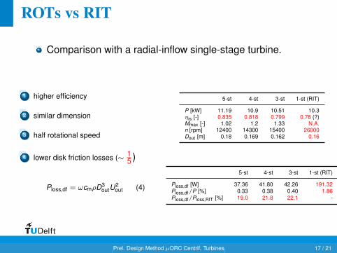
ROTs vs RIT
Comparison with a radial-inflow single-stage turbine.
1 higher efficiency
2 similar dimension
3 half rotational speed
4 lower disk friction losses (∼ 15 )
Ploss,df = ωcmρD3outU
2out (4)
5-st 4-st 3-st 1-st (RIT)
P [kW] 11.19 10.9 10.51 10.3ηis [-] 0.835 0.818 0.799 0.78 (?)Mmax [-] 1.02 1.2 1.33 N.A.n [rpm] 12400 14300 15400 26000Dout [m] 0.18 0.169 0.162 0.16
5-st 4-st 3-st 1-st (RIT)
Ploss,df [W] 37.36 41.80 42.26 191.32Ploss,df/P [%] 0.33 0.38 0.40 1.86Ploss,df/Ploss,RIT [%] 19.0 21.8 22.1 -
E. Casati , S. Vitale , M. Pini , G. Persico , & P. ColonnaPrel. Design Method µORC Centrif. Turbines 17 / 21

Conclusions
zTurbo + optimizer ⇒ reliable and flexible design tool
Novel design strategy for micro centrifugal turbinespresented
centrifugal architecture promising for (micro)ORC systems
E. Casati , S. Vitale , M. Pini , G. Persico , & P. ColonnaPrel. Design Method µORC Centrif. Turbines 18 / 21

THANK YOU FOR YOUR ATTENTION
E. Casati , S. Vitale , M. Pini , G. Persico , & P. ColonnaPrel. Design Method µORC Centrif. Turbines 19 / 21

ReferencesCasci, C. (1979). Macchine a fluido bifase (in Italian). Tamburin.
Cerri, G., Battisti, L., & Soraperra, G. (2003). Non conventional turbines for hydrogenfueled power plants. In Proceedings of the ASME Turbo Expo 2003 GT2003-38324.Atlanta, GA.
Coomes, E., Dodge, R., Wilson, D., & McCabe, S. (1986). Design of ahigh-power-density Ljungstrom turbine using potassium as a working fluid. SanDiego, CA, USA,: Intersociety energy conversion engineering.
Fottner, L. (1990). Test cases for computation of internal flows in aero enginecomponents. AGARD, .
Lang, W., Almbauer, R., & Colonna, P. (2013). Assessment of waste heat recovery fora heavy-duty truck engine using an ORC turbogenerator. Journal of Engineering forGas Turbines and Power-Transactions of the ASME , 135, 042313–1–10.
Macchi, E. (1977). Lecture series 100 on closed-cycle gas turbines. chapter Designcriteria for turbines operating with fluids having a low speed of sound. Von KarmanInstitute for Fluid Dynamics.
Macchi, E. (1985). Design limits: Basic parameter selection and optimization methodsin turbomachinery design. (pp. 805–828). Izmir, Turk: Martinus Nijhoff Publ,Dordrecht, Neth volume 97 A v 2.
Pini, M., Persico, G., Casati, E., & Dossena, V. (2013). Preliminary design of acentrifugal turbine for organic Rankine cycle applications. Journal of Engineering forGas Turbines and Power-Transactions of the ASME , 135, 042312–1–9.
E. Casati , S. Vitale , M. Pini , G. Persico , & P. ColonnaPrel. Design Method µORC Centrif. Turbines 20 / 21

References (cont.)
Sandia National Laboratories (2012). The Dakota project - Large Scale EngineeringOptimization and Uncertainty Analysis. Http://dakota.sandia.gov/software.html (lastaccessed September 2013).
E. Casati , S. Vitale , M. Pini , G. Persico , & P. ColonnaPrel. Design Method µORC Centrif. Turbines 21 / 21