Arthrobots - Harvard University inserted into the tube at the position of the notch (a pneumatic...
15
1 Supplementary Materials for Arthrobots Alex Nemiroski, Yanina Y. Shevchenko, Adam A. Stokes, Baris Unal, Alar Ainla, Sahradha Albert, Gabrielle Compton, Emily MacDonald, Yosyp Schwab, Caroline Zellhofer, and George M. Whitesides Emailed correspondence to: [email protected] SUPPLEMENTARY MOVIES Movie S1. A single, un-sleeved joint actuated at 60 psi. Movie S2. The locomotion of a one-legged crawler. This arthrobot can advance in one direction (forward). Movie S3. The locomotion of a two-legged crawler. This arthrobot can advance in two directions (forward and backward). Movie S4. The locomotion of a four-legged crawler. This arthrobot can advance linearly in four directions (forward, backward, leftward, and rightward). Movie S5. The locomotion of a four-legged walker. This arthrobot can advance linearly in four directions (forward, backward, leftward, and rightward) and differs from the four-legged crawler because the body is raised off the ground. Movie S6. Overhead view of a six-legged walking arthrobot. This arthrobot uses a triangular gait to advance forwards on a horizontal, flat surface. Movie S7. Side view of a six-legged arthrobot walking on an incline. This arthrobot uses triangular gait to climb a flat, cardboard surface at angles up to at 35° from horizontal. Movie S8. Side view of a six-legged arthrobot navigating an obstacle. Movie S9. The locomotion of an eight-legged arthrobot walking on a flat surface. Movie S10. The locomotion of a rowing arthrobot. The movie shows the rowing action, including turning to the right and left, of the arthrobot on the surface of water in a small pool.
Transcript of Arthrobots - Harvard University inserted into the tube at the position of the notch (a pneumatic...

1
Supplementary Materials for
Arthrobots
Alex Nemiroski, Yanina Y. Shevchenko, Adam A. Stokes, Baris Unal, Alar Ainla, Sahradha
Albert, Gabrielle Compton, Emily MacDonald, Yosyp Schwab, Caroline Zellhofer, and George
M. Whitesides
Emailed correspondence to: [email protected]
SUPPLEMENTARY MOVIES
Movie S1. A single, un-sleeved joint actuated at 60 psi.
Movie S2. The locomotion of a one-legged crawler. This arthrobot can advance in one
direction (forward).
Movie S3. The locomotion of a two-legged crawler. This arthrobot can advance in two
directions (forward and backward).
Movie S4. The locomotion of a four-legged crawler. This arthrobot can advance linearly in
four directions (forward, backward, leftward, and rightward).
Movie S5. The locomotion of a four-legged walker. This arthrobot can advance linearly in four
directions (forward, backward, leftward, and rightward) and differs from the four-legged crawler
because the body is raised off the ground.
Movie S6. Overhead view of a six-legged walking arthrobot. This arthrobot uses a triangular
gait to advance forwards on a horizontal, flat surface.
Movie S7. Side view of a six-legged arthrobot walking on an incline. This arthrobot uses
triangular gait to climb a flat, cardboard surface at angles up to at 35° from horizontal.
Movie S8. Side view of a six-legged arthrobot navigating an obstacle.
Movie S9. The locomotion of an eight-legged arthrobot walking on a flat surface.
Movie S10. The locomotion of a rowing arthrobot. The movie shows the rowing action,
including turning to the right and left, of the arthrobot on the surface of water in a small pool.

2
SUPPLMEMENTARY TEXT
Anatomy of a Joint. This design for an actuated arthrobot joint was stimulated by
consideration of key features of the joints found in the legs of spiders. In spiders, pressure is
regulated both locally and globally by muscular contractions around the arteries and Hemolymph
channels (Main Text, Fig. 1). When the limb needs to be retracted, the muscles contract and
hemolymph is emptied from the joints into the dorsal channels. To mimic these actions, our
arthrobot joints incorporated three structural features: i) flexible hinges fabricated in a thin
polypropylene tube by notching; ii) an actuator for this joint comprising an inflatable elastomeric
balloon inserted into the tube at the position of the notch (a pneumatic analog of the
hydraulically actuated hydrostat used in the spiders); iii) an elastomeric band attached on the
inner part of the joint to provide an elastic restoring force after pneumatic extension.
Construction of a Basic Joint. To form exoskeletal limbs we use wide polypropylene
straws (Bubble Tea (“Boba”) straws; purchased from Amazon.com) with an outer diameter of 1-
cm. Supplementary Fig. S1 shows a typical sequence for constructing the joint. To form a hinged
joint, we first cut the straws the size, marked the center and extent of the notch, and then pressed
the straws flat to cut the notch out using two, straight, intersecting cuts (Fig. S1A-D). Multiple
such hinges (with appropriate orientation relative to one another) may be defined in one tube; the
notches define the positions and orientation of these hinges. We next cut a short strip of natural
rubber to form a tendon, bent the exoskeletal joint manually, and affixed the tendon, with tape,
on the inside of the joint, to preserve its bent configuration when the tendon is unstrained. We
next created an elastomeric balloon by cut a 5-cm length of elastomeric tubing (5041K69,
McMaster-Carr), sealing one end with hot-melt adhesive and the other with a female Luer tube
fitting (EW-45508-00, Cole-Palmer). We improved the sealing on both ends by wrapping a thin
strip of plastic parafilm (P7793-1EA, Sigma-Aldrich). To assemble the joint, we attached narrow
silicone (2 mm) tubing to the plastic fitting attached to one end of the balloon, manually
extended the joint, and inserted the deflated balloon such that it spans the length of the notch.
Construction of Reinforced and Stabilized Joints. For the case of the sleeved joint,
before attaching the tendon, we first wrapped a single layer of a non-woven sheet (21914-758,
VWR International) around the joint, then used hot glue to seal the sleeve, and finally attached
tape to fix it in place around the joint. For the eight-legged “spider,” before adding the sleeve, we

3
stabilized all joints by adding an additional folded tube inside the joint (Fig. S2) to reduce
bending out of the hinging plane and to provide greater overall structural support. We added a
second set of elastomeric tendons to these joints to help the limbs return to their initial
configuration after each cycle of actuation. To create the fixed-angle “knees” that we used in the
eight-legged arthrobot, we briefly exposed the tubes to a hot air gun (to soften the tube locally)
and then bent them to the desired angle (the tubes re-solidified within seconds). We also added
“feet” coated with a layer of hot-melt glue to reduce slipping during locomotion.
Mechanics and Lifetime of Joints. We tested the range of extension and life-time of
joints by repeatedly actuating (with a valve, Arduino, and source of compressed air) a single
joint (unconnected to an arthrobot) through consecutive cycles of extension and retraction. The
range of extension of un-sleeved joints was approximately 40˚ (from 100° degrees, fully folded,
to 145°, fully extended; Fig. S3) at 70 kPA. Although we have not optimized them for durability,
repeated testing showed that these joints could last for hundreds of cycles (400 ± 200, N = 7
actuators, 70 kPa) of extension and retraction until the rubber tendons snapped and require
replacement; using pressures higher than ~100 kPa caused the balloons to over-inflate and pop.
The alternative, fiber-reinforced joints that we developed had a larger range of extension—
approximately 70° (from 90° degrees, fully folded, to 160°, fully extended) at 150 kPa—due to
the ability to use higher pressures than the sleeved version. Repeated testing showed that the
sleeved-joints could last for thousands of cycles (10,000 ± 2,000, N = 7 actuators, 150 kPa) of
extension and retraction until the rubber tendons snapped and required replacement; using
pressures higher than ~200 kPa caused the balloons to over-inflate and pop. The increased
lifetime of sleeved joints occurred because the rubber tendons did not need to conform to a
bulging balloon, and therefore only extended up to ~200% of their unstrained length (rather than
up to ~400%, as is the case for the un-sleeved version) at maximum extension (as shown in Main
Text Figs. 1E-F). This characteristic may, in the future, be used to tune motion and gaits more
precisely. For simplicity, in the present work, we assembled most robots using the un-sleeved
version; we used the advanced sleeved joint only when higher forces (high pressures) were
necessary to support and locamote a larger arthrobot (as in the case of the “spider” and “water
strider”).
Set-up for Characterizing Efficiency. Fig. S4 shows the setup we used to characterize
the thermodynamic efficiency of a pneumatic joint. We used an incompressible fluid (water)

4
rather than air to characterize efficiency to reduce the compressive losses outside of the joint. We
fixed the joint in place with a clamp in a water bath (to eliminate any possible influx of air) and
affixed a string to the free end of the joint. We looped the other end of the string over a low-
friction pulley suspended directly above the joint and connected it to a free-hanging mass (m =
20 g). Using a T-fitting, we connected the joint to a syringe pump (PHD 2000, Harvard
Apparatus Inc.) and a pressure transducer (TDH30CG-001503B004, Transducersdirect.com)
powered by a power supply (GPS-3303, GW Instek). To minimize mechanical elasticity
everywhere outside the joint, we tried to minimize the length of tubes and use metallic
connections when possible. We sampled the 0-5Vdc signal from the pressure transducer using an
Arduino UNO (Sparkfun Electronics) and acquired the data continuously with a custom
MATLAB (Mathworks) program. After several cycles of applying negative pressure to the
system and then infusing with water (to eliminate air bubbles) we set the syringe pump to
execute the following sequence: i) starting at an initial pressure of P0 = 0.5 kPa (tuned by hand),
fill (extend) the joint with 1.6 mL of water at a rate of 0.5 mL/min; ii) deplete (retract) the joint
of 1.6 mL of water at a rate of -0.5 mL/min; iii) repeat the sequence automatically. We recorded
the pressure P(t) and volume V(t);
Calculation of Thermodynamic Efficiency of Joints. The efficiency η of the joint is an
important parameter; it characterizes the efficiency of converting the energy Qin input to each
joint into useful mechanical work W. Although there is no single value of η for these joints that
uniquely characterizes their performance—because their force transduction depends strongly on
the type of robot and role that the limb plays in the gait—it is still instructive to estimate this
quantity in a standard case. We estimated the efficiency by η = W /Qin, where Qin is the area
under the measured pressure-volume curve measured i) while unloaded and ii) while performing
mechanical work W lifting a known mass over a known height. Figure S5 shows a plots of the P-
V hysteresis curves for seven consecutive cycles for both loaded and unloaded cases for both an
un-sleeved joint (Fig. S5A) and a sleeved joint (Fig. S5B). We determined the total energy 𝑄𝑒𝑥𝑡
input into the system while extending the joint by calculating 𝑄𝑒𝑥𝑡 = ∫ 𝑃(𝑉)𝑑𝑉𝑉2
𝑉1 and the total
energy 𝑄𝑟𝑒𝑡 recovered form the system while retracting the joint by 𝑄𝑟𝑒𝑡 = ∫ 𝑃(𝑉)𝑑𝑉𝑉1
𝑉2. We
determined the heat lost by ΔQ = Qext – Qret, and the total mechanical work lifting mass m = 20 g
to a height Δh by W = mgh, (g = 9.8 m/s2). The efficiency when extending the joint to lift the

5
mass is given by η = W/Qext. The regular joint lifted the mass by Δh = 4.8 cm and yielded an
efficiency of η = 1%; the remaining energy went into reversible expansion of the balloon /
tendon (90%) or irreversable loss (9%). The sleeved joint lifted the mass by Δh = 6.0 cm and
yielded η = 2%; the remaining energy went into reversible expansion of the balloon / tendon
(76%) or irreversable loss (22%). Because most work goes into the expansion of the elastomeric
elements, it can be decreased by optimized choice of polymer or by replacing the elastomeric
balloons entirely with inextensible pouches that eliminate the reversible, elastic expansion of the
balloon. This approach, however, could slow down the motion of a joint because the elastomeric
tendon would have to perform all the work in the retraction phase.
Measurement of force exerted by extending joints. Using the same fixture shown
submerged in Figure S4 we mounted a joint in the same configuration and placed it over a scale.
We then inflated the joints and measured the force exerted by the joint onto the scale vs. applied
pressure. Figure S6 shows the data we collected (each point a mean value of three different
measurements.)
Additional Simple Crawling Arthrobots. Supplementary Figure S6 shows additional
crawling arthrobots that we constructed: a one-legged crawler, and a four-legged crawler. The
one- and two-legged crawlers shown here (Figs. S7A-B) do not correspond to any animals
currently alive. To increase traction in the case of the one-legged crawler, we added a sticky
layer of gel polymer (cut from “sticky hands” purchased from Amazon.com) to the “foot”. The
four-legged crawler and four-legged walkers (Figs. S7C-D) differ in that the body of the first
rests on the surface, while the body of the second is held above the surface by the legs.
Configuration and Sequence of Actuation of Spider-Inspired Arthrobot. The two
pairs of front and rear legs each contained a pair of joints (e.g. A1, B1) that bent in the same
direction (vertical plane, relative to the ground) to enable the spider to i) pull the body forward
using the tendons of the front legs and ii) push the body forward with active expansion of the
back legs. The two pairs of side legs each contained a pair of joints (e.g. A2, B2) with a relative
orientation of 90˚; the inner joints (B2 in this example) bent in the horizontal plan (relative to the
ground) to enable forward and backward motion, while the outer joints (e.g., A2 in this example)
bent in the vertical plane to lift the leg off the ground or place it back down. We configured all
pairs of legs to be symmetric about both the sagittal and coronal planes of the body to enable the
6
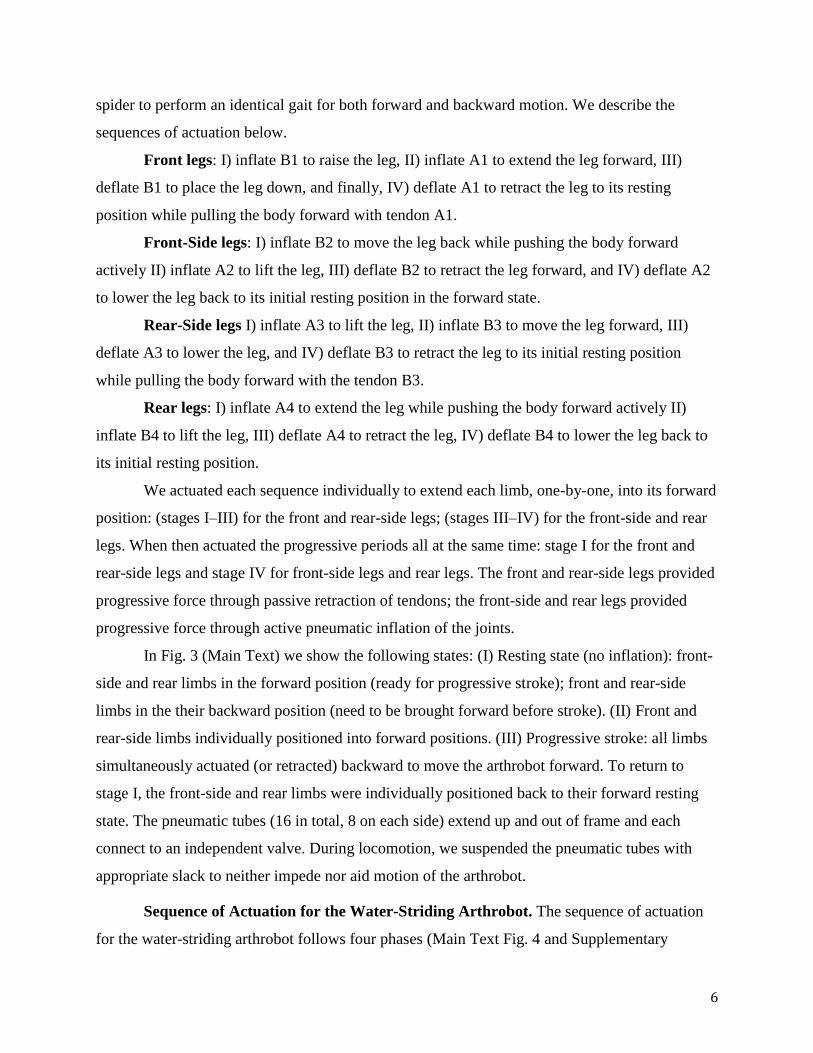
spider to perform an identical gait for both forward and backward motion. We describe the
sequences of actuation below.
Front legs: I) inflate B1 to raise the leg, II) inflate A1 to extend the leg forward, III)
deflate B1 to place the leg down, and finally, IV) deflate A1 to retract the leg to its resting
position while pulling the body forward with tendon A1.
Front-Side legs: I) inflate B2 to move the leg back while pushing the body forward
actively II) inflate A2 to lift the leg, III) deflate B2 to retract the leg forward, and IV) deflate A2
to lower the leg back to its initial resting position in the forward state.
Rear-Side legs I) inflate A3 to lift the leg, II) inflate B3 to move the leg forward, III)
deflate A3 to lower the leg, and IV) deflate B3 to retract the leg to its initial resting position
while pulling the body forward with the tendon B3.
Rear legs: I) inflate A4 to extend the leg while pushing the body forward actively II)
inflate B4 to lift the leg, III) deflate A4 to retract the leg, IV) deflate B4 to lower the leg back to
its initial resting position.
We actuated each sequence individually to extend each limb, one-by-one, into its forward
position: (stages I–III) for the front and rear-side legs; (stages III–IV) for the front-side and rear
legs. When then actuated the progressive periods all at the same time: stage I for the front and
rear-side legs and stage IV for front-side legs and rear legs. The front and rear-side legs provided
progressive force through passive retraction of tendons; the front-side and rear legs provided
progressive force through active pneumatic inflation of the joints.
In Fig. 3 (Main Text) we show the following states: (I) Resting state (no inflation): front-
side and rear limbs in the forward position (ready for progressive stroke); front and rear-side
limbs in the their backward position (need to be brought forward before stroke). (II) Front and
rear-side limbs individually positioned into forward positions. (III) Progressive stroke: all limbs
simultaneously actuated (or retracted) backward to move the arthrobot forward. To return to
stage I, the front-side and rear limbs were individually positioned back to their forward resting
state. The pneumatic tubes (16 in total, 8 on each side) extend up and out of frame and each
connect to an independent valve. During locomotion, we suspended the pneumatic tubes with
appropriate slack to neither impede nor aid motion of the arthrobot.
Sequence of Actuation for the Water-Striding Arthrobot. The sequence of actuation
for the water-striding arthrobot follows four phases (Main Text Fig. 4 and Supplementary

7
Fig. S8). (I) In the starting position, all joints are unpressurized and limbs are in front in contact
with the surface of the water. (II) Joints B1 and B2 are pressurized to move both limbs
backwards and propel the body of the arthrobot forwards. (III) Joints B1 and B2 remain
pressurized while joints A1 and A2 are also now pressurized to lift the two limbs. (IV) All joints
(A1, A2, B1, B2) are all deflated to allow the limbs to returning to their original, passive
position: reaching forward and ready for the next backward stroke.

8
Figure S1. Schematic detailing the construction of a joint. (A) Marking the center of the straw
and the extent of the notch. (B–C) Using a ruler flatten the straw and draw the the outline of the
notch. (D) The joint after the notch is cut out. (E) Bending the joint manually. (F) The joint, after
affixing the elastic tendon with tape (Inset: close-up) shown with the assembled and sealed
elastomeric ballroon connected to tubing. (G) Balloon inserted into the joint (Inset: close-up).
(H) The sleeved version of the joint. The orange straw shown has a diamter of 11 mm.

9
Figure S2. Stabilized Joints. (A) Materials for construction of stabilized joints. A notched tube
for the hinge, a folded tube for stabilization, and a pneumatic actuator. (B) Insertion of the folded
tube. (C) Insertion of the pneumatic actuator. We used this joint exclusively in the eight-legged
“spider”; after construction of each joint, we added a sleeve as in Fig. S1H.

10
Figure S3. Schematics and actuation of arachnid-inspired joints. (A) Schematic illustrating
unpressurized configuration of a single joint. (B) Schematic illustration pressurized joint. (C)
Image of an unpressurized joint. D) Image of the joint pressurized to ΔP0 = 70 kPa. The white
straw shown has a diameter of 7 mm.

11
Figure S4. Schematic showing the set-up used to determine the thermodynamic efficiency of a
joint when it is retracted (A) and extended (B). We used the same set-up to characterize both the
regular and sleeved joint.

12
Figure S5. P-V Energy calculations. (A) (Left) P-V Hysteresis curves for extension and
retraction of a regular (un-sleevd) joint when loaded and unloaded. (Right) Calculated energy
values for un-sleeved joint. (B) (Left) P-V Hysteresis curves for extension and retraction of a
sleeved joint when loaded and unloaded. (Right) Calculated energy values for sleeved joint.

13
Figure S6. Force exerted by sleeved and un-sleeved joints vs applied pressure. The un-
sleeved joints experience snap-through instability beyond 70 kPa leading to the balloon to burst.

14
Figure S7. Images of additional crawling arthrobots. Actuation sequence (I–IV) and motion
of the one-legged crawler (A), two-legged crawler (B), four-legged crawler (C), and four-legged
walker. Diagrams in the left corners of each photograph depict the actuation state of each joint:
blue dots correspond to pressurized actuators; red dots correspond to unpressurized actuators. All
tick spacings corresponds to 2 cm. Black straws pictured here have diameter of 7 mm.

15
Figure S8. Schematic depicting the actuation sequence of an arthrobot inspired by water
striders. I-IV) The four phases of a cyclic, progressive stroke. For each phase, the middle
column shows a schematic of the top view and the right column shows a schematic of the side
view.