Strengthening PBIS in Your School: Tier II Interventions MiBLSi/Ingham ISD Focus Day Training.
Paper 30
Appropriateness of Seismic Strengthening Interventions in Heritage Buildings: A Framework for Appraisal
A.G. Cattanach, G.W. Alley and A.W. Thornton Dunning Thornton Consultants Ltd
2008 NZSEE Conference
ABSTRACT:
New Zealand is entering a critical era in the preservation of its heritage buildings, resulting from the Earthquake-Prone Building provisions of the Building Act 2004. Structural Engineers are often given the task of designing what they believe to be the most appropriate intervention for the building, often without necessarily having the “heritage” skills or external review specialists to aid their decisions.
The following paper suggests a framework under which the appropriateness of structural interventions may be measured. The level of performance of primary and secondary elements are discussed, as well as criteria to judge the appropriateness of each intervention into the historic fabric.
The recent upgrade of Shed 13 on Wellington Waterfront, recipient of a NZIA (Heritage) Architecture Award, is discussed as a case in point. The strengthening utilises a combination of un-bonded post-tensioning of the existing brickwork and hysteretic energy dissipaters as primary load-resisting elements.
1 INTRODUCTION
The Building Act 2004, with its redefinition of Earthquake-Prone Buildings (EPBs) based on load-resisting characteristics rather than material composition, is placing a large proportion of New Zealand’s heritage buildings in the hands of our earthquake engineers. They are required to appraise seismic performance, often in a very short space of time, against the requirements of the Act and the various by-laws put in place by the local authorities. This improvement is supposed to represent the wants and needs of our communities but do structural engineers have the skills and experience to make the decisions regarding heritage fabric interventions by themselves?
Structural Engineers are often presented with the dilemma of matching improved seismic performance with the heritage objectives of minimising intervention. Frequently the argument made that a heritage structure deemed worthy of protection and preservation should be exempted from full-code requirements in order to minimise the amount of intervention and modification of the heritage form and fabric. This provides the structural engineer with the challenge of understanding heritage objectives and of getting the most out of the existing structure by intermeshing the performance of any new structure with that of the old.
During the Scheme Design/Resource Consent process for Shed 13 - a heritage listed building on Wellington’s waterfront - the writers prepared a strengthening options report which included many of the criteria presented here. The positive effect this appraisal had on the structural scheme, including some innovative technical aspects of the strengthening, contributed to the recent NZIA Architecture Award (Heritage) award this work received.
The purpose of this paper is to present a suggested appraisal framework for assessment of the appropriateness of a structural strengthening design. It is intended that the framework be applied not just to listed heritage buildings, but all existing buildings that have an economic and cultural value. It is intended that there be further discussion on the heritage ideals suggested, to raise general awareness of heritage issues in the engineering community. If we are to become a truly sustainable nation we cannot afford to lose the culture and embodied energy we value in our heritage buildings.
2
2 Analysis Framework for Strengthening Interventions
2.1 Performance
One of the key reasons for this paper is to build on the recent change in mindset in the profession from “interim securing”, or strengthening of the perceived weaknesses in a structure, to the performance-based appraisal of the building as a whole.
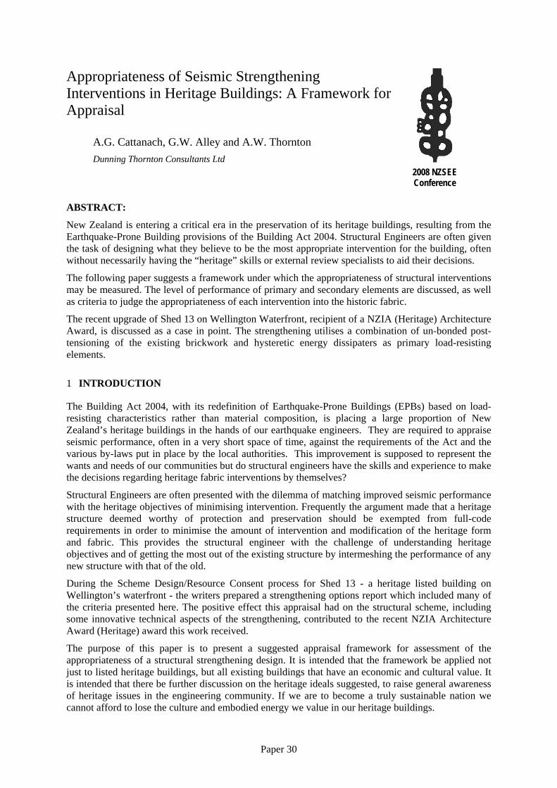
Advances in seismic engineering between 1960 and the end of the century (aside from the introduction of base-isolation) tended to concentrate on maximising the life-preservation performance for a lesser and lesser cost. Seismic strengthening grew as a speciality; generally securing/demolishing parapets, tying walls to floors, and inserting primary frames where there was little or negligible strength. While these interventions significantly improved the performance of dangerous buildings, the range of application (and undoubtedly likely performance) varied widely. Strength-based design does not explicitly force the designer to address deflection compatibility, so it was up to the individual designer to set deflection criteria (or not). With (commonly used) steel frames, deflection is often the governing criteria, but design decisions are made with an underlying pressure from the client to minimise the cost of intervention. The classic example of lack of consideration for compatibility is cross bracing in parallel to relatively massive solid masonry walls (Figure 1).
Figure 1: Cross bracing parallel to relatively massive piers
Arguments made to justify such interventions, such as: “the façade will collapse and the bracing be left to hold the floors” are unlikely to withstand an impact/robustness appraisal, or in the case of a historically/architecturally significant building, consideration that the original fabric (and with that much of the purpose for strengthening) will be lost.
Strengthening is a complex art and, especially for a heritage building, should not be merely the insertion of a new modern building’s structure inside an old.
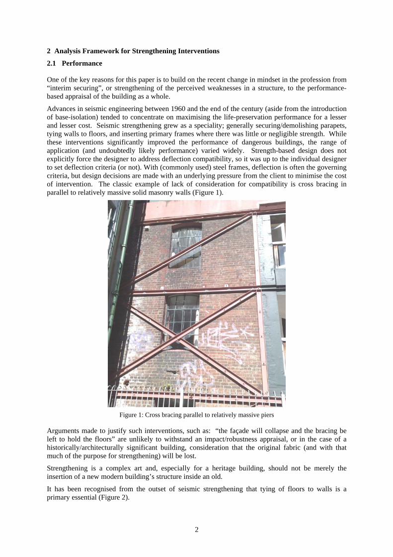
It has been recognised from the outset of seismic strengthening that tying of floors to walls is a primary essential (Figure 2).
3
Odlins Building in 2001 (now redeveloped to the NZX Centre): band beams installed during 1940’s strengthening sandwiching brickwork and tying back to the internal timber floors (Figure 2)
Inherently, this forces equal displacement of all elements and hence the strength/stiffness properties of new and existing must be considered together. Even in structures with inherently flexible diaphragms such as churches or one-storey industrial buildings, the existing distributed strength from buttresses, cantilever columns or the like will always have a limit of displacement where first damage will occur. This limit should be understood before a strengthening scheme is contemplated.
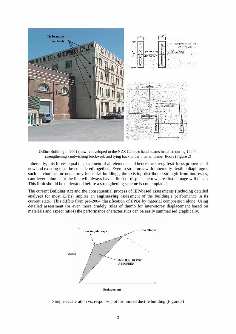
The current Building Act and the consequential process of IEP-based assessments (including detailed analyses for most EPBs) implies an engineering assessment of the building’s performance in its current state. This differs from pre-2004 classification of EPBs by material composition alone. Using detailed assessment (or even more crudely rules of thumb for inter-storey displacement based on materials and aspect ratios) the performance characteristics can be easily summarised graphically.
Simple acceleration vs. response plot for limited ductile building (Figure 3)
Tie beams at floor levels
4
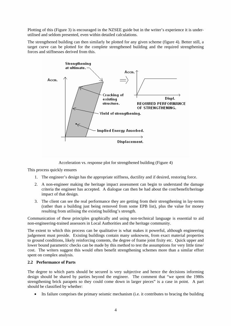
Plotting of this (Figure 3) is encouraged in the NZSEE guide but in the writer’s experience it is under-utilised and seldom presented, even within detailed calculations.
The strengthened building can then similarly be plotted for any given scheme (figure 4). Better still, a target curve can be plotted for the complete strengthened building and the required strengthening forces and stiffnesses derived from this.
Acceleration vs. response plot for strengthened building (Figure 4)
This process quickly ensures
1. The engineer’s design has the appropriate stiffness, ductility and if desired, restoring force.
2. A non-engineer making the heritage impact assessment can begin to understand the damage criteria the engineer has accepted. A dialogue can then be had about the cost/benefit/heritage impact of that design.
3. The client can see the real performance they are getting from their strengthening in lay-terms (rather than a building just being removed from some EPB list), plus the value for money resulting from utilising the existing building’s strength.
Communication of these principles graphically and using non-technical language is essential to aid non-engineering-trained assessors in Local Authorities and the heritage community.
The extent to which this process can be qualitative is what makes it powerful, although engineering judgement must preside. Existing buildings contain many unknowns, from exact material properties to ground conditions, likely reinforcing contents, the degree of frame joint fixity etc. Quick upper and lower bound parametric checks can be made by this method to test the assumptions for very little time/ cost. The writers suggest this would often benefit strengthening schemes more than a similar effort spent on complex analysis.
2.2 Performance of Parts
The degree to which parts should be secured is very subjective and hence the decisions informing design should be shared by parties beyond the engineer. The comment that “we spent the 1980s strengthening brick parapets so they could come down in larger pieces” is a case in point. A part should be classified by whether:
• Its failure comprises the primary seismic mechanism (i.e. it contributes to bracing the building
5
in either of the directions).
• Its collapse poses a significant life risk in itself.
• Its damage or collapse is historically unacceptable or unrepairable.
A wider range of strengthening strategies can then be investigated based on risk.
Preservation of a part for its own merit, or integrity of the building’s bracing implies a requirement for damage and displacement control in the primary structure and should be addressed as such.
Life safety, however, can be addressed by using broader risk-management strategies. These might involve assessment of the maximum size/height of the falling object, or the containment of damage using wall linings, intermediate floors/ceilings or the like. One common example is when the securing of plaster and faience on a façade is uneconomic or too intrusive to the historic fabric: instead the public is protected by reinforcement of the street canopy. Again this is a decision which should be shared with other experts and/or interested parties where possible through the resource and building consent process.
Pounding between adjacent buildings including those sharing a common wall are extremely complex technical and legal issues and as such are considered outside the scope of this paper.
2.3 Appropriateness
The aim of having a purely subjective framework to appraise the appropriateness of a strengthening scheme for a heritage building is twofold;
1. to identify positive traits of appropriate heritage design.
2. for the designer to express the underlying quality assumptions that have influenced their decision making. Comment can then be made without the bias of the technical knowledge held by the engineer.
In general the philosophy should be “to do as much as necessary, but as little as possible”: the client and heritage community will certainly agree on this!
Firstly, at schematic design level, the appropriateness of POSITIONING should be considered. Where appropriate, the engineer should ensure the heritage “structure” and form is not masked, covered or lost. Key heritage aspects include:
• Plan footprint, especially of foundations and primary structure
• Primary circulation (the user experience of a building)
• Scale, mass and material distribution, how it reads architecturally
• Façades and relation to street/surroundings
• Views/sightlines to and into the building
The original structure should still be read insitu against any backdrop of seismic strengthening. Similarly interventions should, as much as practicable, be located in areas of lower heritage value
As structural engineers we should have empathy for the original structure of the building. Certainly, if heritage is considered in the period greater than 200 years, structure become the dominant lasting feature. It is the writers’ belief that an experienced engineer is best placed to “read” the original designer’s (Mason’s?) intentions beneath the layers of history accumulated on top of the structure. This assistance should be given to the other building professionals involved. Finishes can be more overt and simply understood.
At the detail level features that are historical should be identified, especially if they are unique, irreparable or irreplaceable.
The proposed DETAILS can then be audited against for MINIMUM INTERVENTION and
6
adjustments made where physically practicable – connections can be made into the less historically important elements.
Minimising change to the existing load paths is an inherent part of retaining the existing structural footprint of the building. In this way, if the EXISTING BENEFICIAL STRENGTH can be used, the intervention will naturally tend to be more economic and more sensitive.
REVERSIBILITY is an acknowledgement of the fallibility of our work; techniques may change sufficiently in the future that the proposed strengthening may become seen as inappropriate relative to the heritage fabric. More importantly in the short term, reversibility can encourage greater transparency between old and new elements and less interventional detailing. This is especially so when a structure has many uses over its preserved life. Strengthening members may need to change in size and position, e.g. strengthening walls moved or exterior additions added or removed. Heritage buildings, if treated sensitively, are best conserved when they are used/occupied and hence the economic means are provided for their upkeep. The planning flexibility around the structure contributes much to the usability and reusability of a building.
TRANSPARENCY in the detailing (separating in material, technique, or form) aids the reading of a heritage structure after strengthening. Even if the addition is “in keeping” with their original style it should be discernible to the educated eye without destructive investigation. It allows the building to be seen in the future as a history built up in layers without relying on retained documentation to describe the picture.
This can usually be achieved using BEST CURRENT TECHNOLOGY. Materials and techniques naturally evolve with time, which should make periodic interventions naturally different from each other. While engineering should not follow fashion rather than sound technical principles, designs as with architecture tend to be branded by their era. We would hope that our advancing science in analysis and simulation techniques, non-ferrous and composite materials, computer-controlled manufacture, and modern adhesives/epoxy matrices, should enable us to do better in the future as long as we do not lose the guidance of good/sensitive designs from the past.
Rediscovery and reinterpretation of traditional techniques is a good example of this. Inspiration for technical structural solutions can often be drawn from traditional buildings, even though this is not commonly done. A timber beam may have been bowstring trussed in late Georgian or early Victorian times because the available materials could not perform on their own. Similarly an existing beam now may be strengthened by bowstring trussing using high tensile steel without obtrusive machined fixings. Corrosion-prone cast iron cavity ties and bed joint reinforcement can be replaced by corrosion-proof plastics or glass/carbon composites having strength and stiffness in the way originally intended.
3
4 EXAMPLE: SHED 13.
3.1 Description
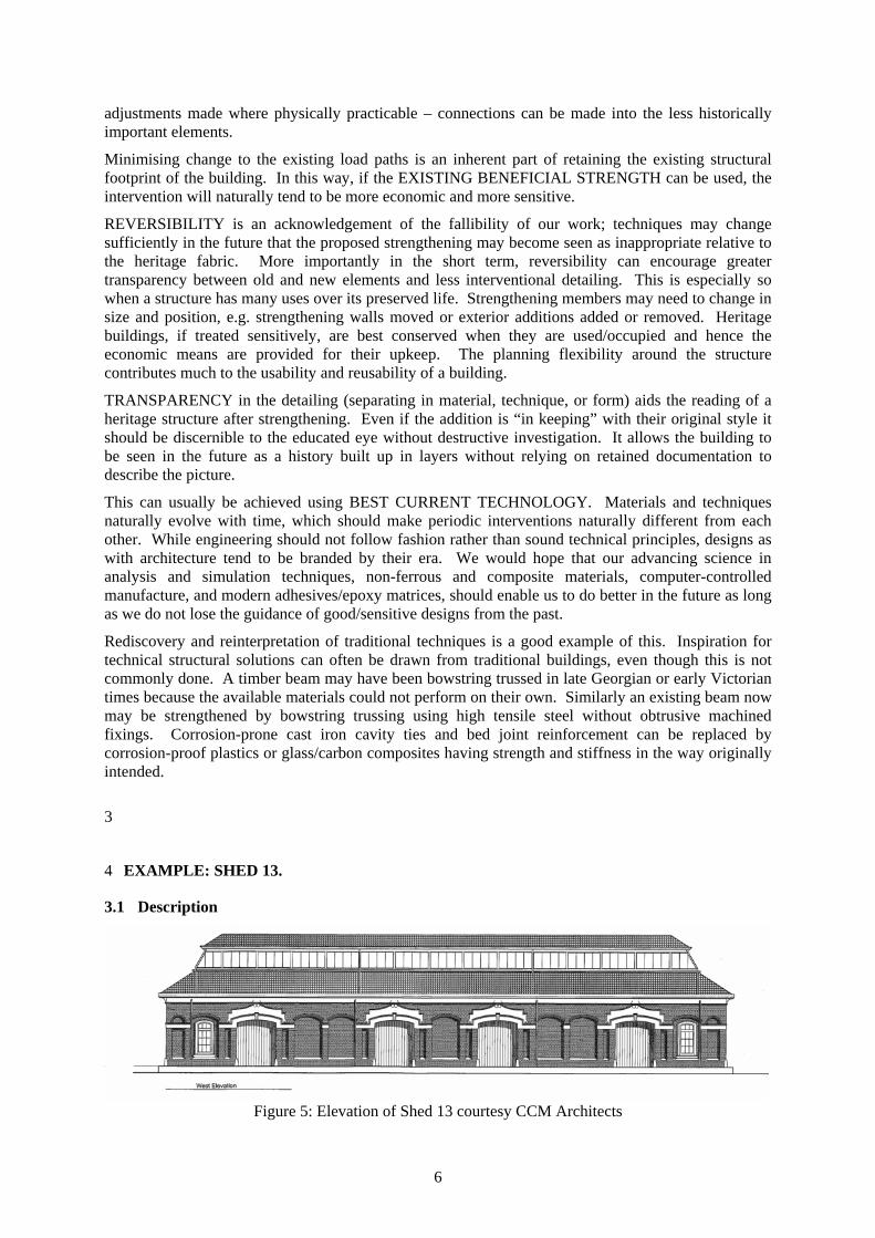
Figure 5: Elevation of Shed 13 courtesy CCM Architects
7
Shed 13 is a single-storey un-reinforced masonry warehouse structure, built circa 1903 on the Wellington waterfront. The building is characteristically long, tall and relatively narrow; at approximately 50m in length, 6.5m in height and 10m in width respectively. An un-reinforced perimeter load-bearing wall encloses the building and supports the tiled roof structure.
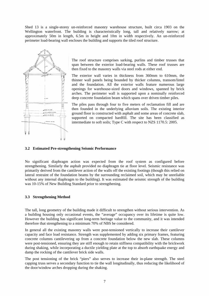
The roof structure comprises sarking, purlins and timber trusses that span between the exterior load-bearing walls. These roof trusses are then fixed to the masonry walls via steel rods at either end.
The exterior wall varies in thickness from 360mm to 610mm, the thinner wall panels being bounded by thicker columns, transom/lintel and the foundation. All the exterior walls feature numerous large openings for warehouse-sized doors and windows, spanned by brick arches. The perimeter wall is supported upon a nominally reinforced deep concrete foundation beam which spans over driven timber piles.
The piles pass through four to five meters of reclamation fill and are then founded in the underlying alluvium soils. The existing interior ground floor is constructed with asphalt and some areas of concrete slab, supported on compacted hardfill. The site has been classified as intermediate to soft soils; Type C with respect to NZS 1170.5: 2005.
3.2 Estimated Pre-strengthening Seismic Performance
No significant diaphragm action was expected from the roof system as configured before strengthening. Similarly the asphalt provided no diaphragm tie at floor level. Seismic resistance was primarily derived from the cantilever action of the walls off the existing footings (though this relied on lateral restraint of the foundation beams by the surrounding reclaimed soil, which may be unreliable without any internal diaphragm to the building). It was estimated the seismic strength of the building was 10-15% of New Building Standard prior to strengthening.
3.3 Strengthening Method
The tall, long geometry of the building made it difficult to strengthen without serious intervention. As a building housing only occasional events, the “average” occupancy over its lifetime is quite low. However the building has significant long-term heritage value to the community, and it was intended therefore that strengthening to a minimum 70% of NBS be considered.
In general all the existing masonry walls were post-tensioned vertically to increase their cantilever capacity and face load resistance. Strength was supplemented by adding six primary frames, featuring concrete columns cantilevering up from a concrete foundation below the new slab. These columns were post-tensioned, ensuring they are stiff enough to retain stiffness compatibility with the brickwork during shaking, while incorporating a ductile yielding plate at the top to absorb earthquake energy and damp the rocking of the cantilever brick side walls.
The post tensioning of the brick “piers” also serves to increase their in-plane strength. The steel capping truss serves a secondary function to tie the wall longitudinally, thus reducing the likelihood of the door/window arches dropping during the shaking.
8
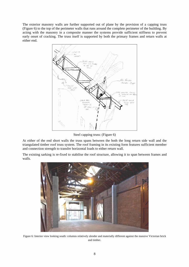
The exterior masonry walls are further supported out of plane by the provision of a capping truss (Figure 6) to the top of the perimeter walls that runs around the complete perimeter of the building. By acting with the masonry in a composite manner the systems provide sufficient stiffness to prevent early onset of cracking. The truss itself is supported by both the primary frames and return walls at either end.
Steel capping truss: (Figure 6)
At either of the end short walls the truss spans between the both the long return side wall and the triangulated timber roof truss system. The roof framing in its existing form features sufficient member and connection strength to transfer horizontal loads to either return wall.
The existing sarking is re-fixed to stabilise the roof structure, allowing it to span between frames and walls.
Figure 6: Interior view looking south: columns relatively slender and materially different against the massive Victorian brick
and timber.
9
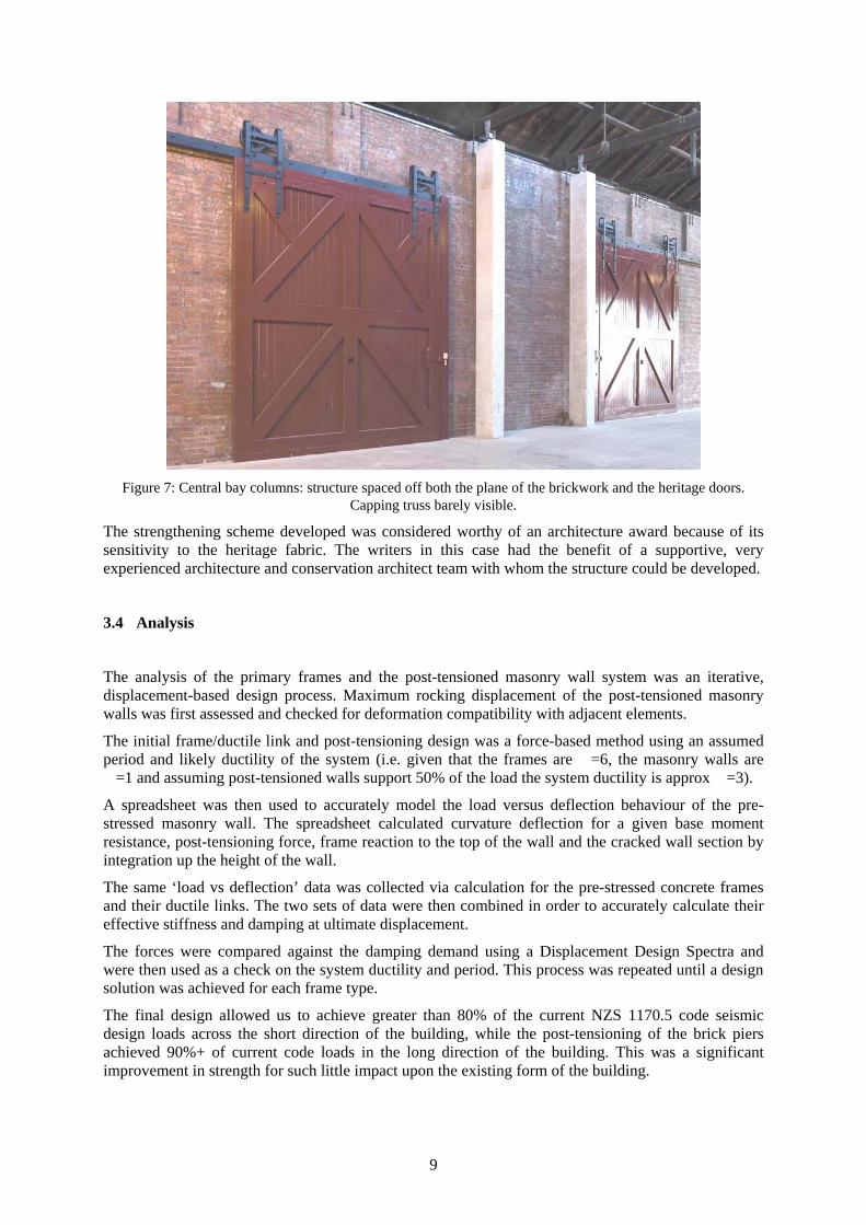
Figure 7: Central bay columns: structure spaced off both the plane of the brickwork and the heritage doors.
Capping truss barely visible.
The strengthening scheme developed was considered worthy of an architecture award because of its sensitivity to the heritage fabric. The writers in this case had the benefit of a supportive, very experienced architecture and conservation architect team with whom the structure could be developed.
3.4 Analysis
The analysis of the primary frames and the post-tensioned masonry wall system was an iterative, displacement-based design process. Maximum rocking displacement of the post-tensioned masonry walls was first assessed and checked for deformation compatibility with adjacent elements.
The initial frame/ductile link and post-tensioning design was a force-based method using an assumed period and likely ductility of the system (i.e. given that the frames are �=6, the masonry walls are �=1 and assuming post-tensioned walls support 50% of the load the system ductility is approx �=3).
A spreadsheet was then used to accurately model the load versus deflection behaviour of the pre-stressed masonry wall. The spreadsheet calculated curvature deflection for a given base moment resistance, post-tensioning force, frame reaction to the top of the wall and the cracked wall section by integration up the height of the wall.
The same ‘load vs deflection’ data was collected via calculation for the pre-stressed concrete frames and their ductile links. The two sets of data were then combined in order to accurately calculate their effective stiffness and damping at ultimate displacement.
The forces were compared against the damping demand using a Displacement Design Spectra and were then used as a check on the system ductility and period. This process was repeated until a design solution was achieved for each frame type.
The final design allowed us to achieve greater than 80% of the current NZS 1170.5 code seismic design loads across the short direction of the building, while the post-tensioning of the brick piers achieved 90%+ of current code loads in the long direction of the building. This was a significant improvement in strength for such little impact upon the existing form of the building.
10
3.5 Shed 11 Strengthening
Shed 13 is the “sister” of the adjacent Shed 11. Shed 11 was strengthened in the mid 1980s by the Wellington Harbour Board/Ministry of Works. It is expected that the strengthening was carried out to the full loadings from NZS 1900 Chapter 8: 1965 (to be confirmed). These loads are approximately one-third of those required by New Building Standard. Major load-resisting elements were introduced along the building at approximately every second bay, cut into the existing brickwork. No roof diaphragm strengthening appears to have been carried out, though this may not have been required by the low levels of seismic load considered. Awareness of the importance of diaphragm action and seismic deflections has also increased significantly since this strengthening.
Shed 13: Assessment against criteria:
Level of Performance
Assessment
Level of strengthening that is appropriate, as a proportion of current code, according to risk and impact of intervention
• 70% of code or greater targeted, balancing risk and heritage value against the difficult tall narrow geometry
Compatibility with the existing structure: at what level of shaking does damage occur to the existing structure, and how does this damage progress/worsen as the shaking level increases?
• Post-tensioning and capping truss limits cracking during smaller levels of shaking.
• Post yield mechanism involves side walls rocking at their base - repairable
Degree secondary elements are secured (weighing up risk to life vs. severity of damage/”repairability” vs. severity of intervention)
• Arches tied without intrusive secondary support
• All walls strengthening by post tensioning – no “sacrificial” secondary elements.
Appropriateness of strengthening/interventions
Ensuring that critical heritage features are subject to MINIMUM INTERVENTION: POSITIONING and DETAILS
• Post-tensioning concealed generally inside perimeter wall
• Structure not cut into existing fabric
• New primary structure separated from side walls generally: “touches” the existing as lightly as possible
• Top perimeter truss discrete, mostly hidden on top of wall
Where appropriate, ensuring the heritage “structure” is not lost
• No structural demolition proposed
Ensuring all EXISTING BENEFICIAL STRENGTH has been considered
• Used, and supplemented by post-tensioning.
REVERSIBILITY • New primary structure offset inside existing walls so “removable”
TRANSPARENCY • New structure of different shape and
11
material to existing: visually different
Designs reflect BEST CURRENT TECHNOLOGY
• Flag shape hysteresis: restores structure to original position
• Utilising post-tensioning of the primary concrete elements in seismic situations to maximise stiffness for size
Shed 11: Assessment against criteria:
Level of Performance
Assessment
Level of strengthening that is appropriate, as a proportion of current code, according to risk and impact of intervention
• Strengthening approximately 30-35% NBS, to the then NZS 1900 Ch8 levels
Compatibility with the existing structure: at what level of shaking does damage occur to the existing structure, and how does this damage progress/worsen as the shaking level increases?
• Strengthening frame flexibility means brick wall hinging occurs early
• Ultimate displacement capacity of strengthening likely well beyond brittle failure in crushing of the brick walls in flexure at the base.
Degree secondary elements are secured (weighing up risk to life vs. severity of damage/”repairability” vs. severity of intervention)
• Brick above horizontal tie beam, which also supports external cornice, effectively unsupported
• Upper heavy roof may suffer distress depending on fixity of sarking.
Appropriateness of strengthening/interventions
Ensuring that critical heritage features are subject to MINIMUM INTERVENTION: POSITIONING and DETAILS
• Roof intervention minimal
• Horizontal and vertical primary frame sawcut and part-housed into existing brick.
Where appropriate, ensuring the heritage “structure” is not lost
• Brick lost at sawcuts.
• Internal pier layout altered as now dominated by strengthening grid.
Ensuring all EXISTING BENEFICIAL STRENGTH has been considered
• Existing strength not used.
REVERSIBILITY • Sawcutting into brick: non-reversible
TRANSPARENCY • Materially different from brick
• Depth of frames masked by sawcutting into brick.
Designs reflect BEST CURRENT TECHNOLOGY
• Average for time.

12
4 Conclusion:
Strengthening very complex technical art. The requirements of the recent Building Act will throw Structural Engineer’s performance of this art into the public view. It is important that the work we do in this field is seen to be appropriate in the Public’s view for the sake of the profession.
Engineering professionals have a key role in strengthening and therefore retention of our heritage stock. Similarly they have a key role in ensuring they do not inadvertently damage quality heritage fabric unnecessarily during these interventions. In a seismic event, we want to avoid the situation where although the strengthening has theoretically performed well, it has failed to live up to the heritage preservation desires of the community.
The framework proposed is intended to encourage engineers to self assess their own designs for appropriateness in heritage terms. It is a simple framework which should take little time to complete as it requires little technical detail.
Correspondingly it should present the strengthening design in a way that it is easy for Resource Consent assessors to understand where the seismic issues are without needing detailed engineering knowledge. Similarly it should aid the assessors to appreciate the extent of their own understanding of the strengthening design, and if necessary obtain what would be a very simple qualitative peer review from another engineer to assist their assessment.
It should be stressed that the framework is intended to be an assessment for just the structural intervention, and not the heritage impact of the whole project.
Retaining our quality existing buildings is a key part of the sustainability of the construction sector and our communities. The refinement and communication of the work we do here is an opportunity for wider understanding of the contribution our profession makes to society.
5 Acknowledgements:
The authors would like to thank the following parties for their supportive teamwork with the building project and for their review of this paper:
Architect – CCM Architects – John Rogers
Conservation Architect – Ian Bowman
WCC Urban Development – Gerald Blunt
REFERENCES:
NZ Historic Places Trust: Sustainable Management of Historic Heritage Guidance Sheets 12-14
www.historic.org.nz/publications/SustMgt_guidance_series.html