w10_borri New Materials for Strengthening and Seismic Upgrading Interventions FRP
23
New Materials for Strengthening and Seismic Upgrading Interventions Antonio Borri 1 , Marco Corradi 1 , Andrea Vignoli 2 1 University of Perugia, Department of Civil and Environmental Engineering, Via Duranti, 93 – 06125 Perugia, Italy 2 University of Florence, Department of Civil Engineering, Via di S. Marta, 3 – 50139 Florence, Italy 1. Abstract This paper focuses on the use of Fiber Reinforced Polymers (FRP) for strengthening and seismic upgrading interventions applied to existing wood and masonry structures. In order to study the performance of wood beams strengthened with FRP materials, several un- strengthened specimens and beams were tested under four point bending up to the point of failure. Other wood specimens and beams were strengthened with externally bonded carbon, glass or aramidic fiber-reinforced polymer (respectively CFRP, GFRP and KFRP) sheets. The second part of the investigation relates to the interventions on masonry buildings. The results of tests carried out on masonry elements show that the application of FRP materials may provide increases in tensile and shear strength. The use of carbon and glass FRP as a reinforcing method for different kinds of masonry elements (vaults, arches, walls, cells, etc) as well as the different possible position s of the FRP sheets, is analyzed, and some solutions are proposed to avoid peeling problems, increase the value of strength and the efficiency of the bond surface. Experimental results are reported along with the case history of the Town Hall of Assisi, where useful indications were obtained on the practical strengthening operations of the masonry vaults. It is therefore important to recognize that the study and the arrangement of the bonding is the key to optimize the structural behavior of strengthened wood and masonry elements. 2. Introduction Many un-reinforced wood and masonry structures are widely present throughout Italy and other regions around the world. These structures seem to suffer the most severe damage during earthquakes. Not only the prohibitive cost of replacing all substandard structures, but also the conservation of the historic heritage of the country, necessitates the development of innovative techniques for rehabilitating deteriorating structures. As a consequence most of these structures need strengthening or seismic upgrading work in order to ensure their conservation and functional use. Table 1 shows the possible application s of FRP materials for strengthening and seismic upgrading interventions. 3. Innovative materials applied on wo od str uctures 3.1 Introduction The use of composite materials to reinforce wood elements is not new. Tendons for prestressed elements were developed by Rubinsky and Rubinsky (1954) [1] and by Kaifasz (1960) [2]. High-strength lightweight cables for applications on cable-supported structures, like bridges, were studied by Meier (1987) [3]. Fujisaki et al (1987) [4] and Saadatmanesh and Ehsani (1989) [5] analyzed the possibility to replace the steel classically used as a reinforcement in concrete structures by composite rebars, and demonstrated that the response of these materials under load can be predicted using the analytical methods known
-
Upload
magdy-bakry -
Category
Documents
-
view
219 -
download
0
Transcript of w10_borri New Materials for Strengthening and Seismic Upgrading Interventions FRP

7/30/2019 w10_borri New Materials for Strengthening and Seismic Upgrading Interventions FRP
http://slidepdf.com/reader/full/w10borri-new-materials-for-strengthening-and-seismic-upgrading-interventions 1/23
New Materials for Strengthening and Seismic UpgradingInterventions
Antonio Borri1, Marco Corradi1, Andrea Vignoli2
1 University of Perugia, Department of Civil and Environmental Engineering, Via Duranti, 93 –
06125 Perugia, Italy2 University of Florence, Department of Civil Engineering, Via di S. Marta, 3 – 50139Florence, Italy
1. Abstract
This paper focuses on the use of Fiber Reinforced Polymers (FRP) for strengtheningand seismic upgrading interventions applied to existing wood and masonry structures. Inorder to study the performance of wood beams strengthened with FRP materials, several un-
strengthened specimens and beams were tested under four point bending up to the point of failure. Other wood specimens and beams were strengthened with externally bonded carbon,glass or aramidic fiber-reinforced polymer (respectively CFRP, GFRP and KFRP) sheets.The second part of the investigation relates to the interventions on masonry buildings. Theresults of tests carried out on masonry elements show that the application of FRP materialsmay provide increases in tensile and shear strength. The use of carbon and glass FRP as areinforcing method for different kinds of masonry elements (vaults, arches, walls, cells, etc)as well as the different possible positions of the FRP sheets, is analyzed, and some solutionsare proposed to avoid peeling problems, increase the value of strength and the efficiency of the bond surface. Experimental results are reported along with the case history of the TownHall of Assisi, where useful indications were obtained on the practical strengtheningoperations of the masonry vaults. It is therefore important to recognize that the study and the
arrangement of the bonding is the key to optimize the structural behavior of strengthenedwood and masonry elements.
2. Introduction
Many un-reinforced wood and masonry structures are widely present throughout Italyand other regions around the world. These structures seem to suffer the most severedamage during earthquakes. Not only the prohibitive cost of replacing all substandardstructures, but also the conservation of the historic heritage of the country, necessitates thedevelopment of innovative techniques for rehabilitating deteriorating structures. As aconsequence most of these structures need strengthening or seismic upgrading work in
order to ensure their conservation and functional use. Table 1 shows the possibleapplications of FRP materials for strengthening and seismic upgrading interventions.
3. Innovative materials applied on wood structures
3.1 Introduction
The use of composite materials to reinforce wood elements is not new. Tendons for prestressed elements were developed by Rubinsky and Rubinsky (1954) [1] and by Kaifasz(1960) [2]. High-strength lightweight cables for applications on cable-supported structures,like bridges, were studied by Meier (1987) [3]. Fujisaki et al (1987) [4] and Saadatmaneshand Ehsani (1989) [5] analyzed the possibility to replace the steel classically used as a
reinforcement in concrete structures by composite rebars, and demonstrated that theresponse of these materials under load can be predicted using the analytical methods known

7/30/2019 w10_borri New Materials for Strengthening and Seismic Upgrading Interventions FRP
http://slidepdf.com/reader/full/w10borri-new-materials-for-strengthening-and-seismic-upgrading-interventions 2/23
to practical engineering. The greatest advantage of these materials was their resistance tocorrosion.
TABLE 1: Possible interventions using FRP materials
Type of intervention using FRP materials Related problems
Wood
structures
Flexural reinforcement of wood beams using FRP
sheets and re-bars epoxy-bonded or inserted inwood-beams in tension zone;
Shear reinforcement of wood beams
Masonry structures
Shear reinforcement of masonry walls using FRPsheets epoxy-bonded to masonry walls or embedding FRP re-bars mounted near thesurface of masonry walls;
Flexural reinforcement of masonry walls
Seismic upgrading intervention on masonry
vaults using FRP sheets;
Confinement of masonry columns with FRPsheets;
Provisional intervention in order to put in securitydamaged masonry buildings;
Connection of multiple leaf masonry walls (re-bars).
Adhesion between FRP materials and
wood/masonry surface;
Aging behavior of reinforcement andadhesion;
High and low temperatures behavior;
Connections of different shapes of FRPmaterials;
Dynamic behavior of the reinforcedstructures;
Types of mortars used in order toleveling masonry surfaces to which theFRP sheets are bonded;
Creep behavior;
Monitoring methods of reinforcedstructures (adhesion faults, decreasesin mechanical properties of newmaterial, etc)
Ranisch and Rostasy (1986) [6], and Saadatmanesh and Ehsani (1989) [5] analyzed the
possibility to increase the strength of existing structural members with epoxy-bonded fiber-composite sheets. This application involved external bonding of thin fiber reinforcedcomposite sheets on the tension face of beams using epoxy resins. These studiesdemonstrated that monodirectional composite sheets are ideal tension reinforcements, andthat they provide an important increase in the stiffness characteristics of a structure.Triantafillou and Deskovic (1991) [7] developed this methodology analyzing the effectsobtained by pretensioning the composite sheets before gluing them on the tension face of the beams. They also proposed to apply this technique to increase the strength of existingwood structural members. Before this, all the studied techniques were applied only in thecase of concrete and reinforced concrete structures.
Plevris and Triantafillou (1992) [8] focused on the development of a fundamental
understanding of the behavior of the fiber reinforced wood systems. They examined theeffect of external bonding of composite materials on the failure mechanisms, the stiffness,and the ductility of the hybrid member subjected to a combination of bending and axial loads.Thanks to an incremental numerical procedure they concluded that even very small areafractions of fiber-composite reinforcement result in significant improvements of the member'smechanical behavior. Because this technique allows the structural recovery of also verydeteriorated wood, it represents a very interesting possibility for all these country where oldand historic monuments are common, which is the case of Italy.
In this section the results of a systematic series of tests on reinforced and non-reinforced wood elements are presented. Three different types of wood, different types of fiber reinforced composite materials (FRP), and samples having different geometry havebeen used. Samples realized using a technique allowing a pretensioning of the composite
sheets have been also tested. The results obtained demonstrated that external bonding of composite materials on wood elements, results in significant improvements of the member'smechanical behavior.

7/30/2019 w10_borri New Materials for Strengthening and Seismic Upgrading Interventions FRP
http://slidepdf.com/reader/full/w10borri-new-materials-for-strengthening-and-seismic-upgrading-interventions 3/23
3.2 Materials and experimental procedures
3.2.1 Materials
Chestnut wood (Castanea Vesca), oak wood (Quercus Cerris) and fir wood (Abies Alba)have been used for the experimentation. About chestnut and oak, very old woods obtainedfrom ancient buildings situated in central Italy (Umbria), and classified as 1 st type wood(wood having very low percentage of defects) [9], have been used. About fir, wood
classifiable as 3rd type wood (wood having diffused defects) has been used.
The hygrometric conditions of these materials have been measured according to theUNI 9091/2 standards [10]; the humidity percentage resulted equal to 9%, 11% and 15%respectively for chestnut, oak and fir woods. The density of these woods resultedrespectively equal to 5.40, 8.98 and 4.24 kN/m3.
The composite reinforcements have been realized using three different types of fibersproduced by MAC spa, respectively carbon (CFRP), glass (GFRP) and aramidic fibers(KFRP), having the physical and mechanical characteristics reported in Table 2 as furnishedby the producer. Depending on the wood used, small samples or large beams were tested. Inthe fist case 400 mm long 20 mm large fiber sheets have been used. In the second case1900 mm long 70 mm large fiber sheets have been used. In the two cases, the thickness of the dry plies was 0.165, 0.118 and 0.070 mm respectively for carbon (CFRP), glass (GFRP)and aramidic fibers (KFRP).
TABLE 2: Mechanical characteristics of the reinforcements (as reported by the producer)
Carbon Fibres Aramidic Fibres E Glass Fibres
Aerial density Ds, [Kg m-2
] 0.300 1440 0.300Ply equivalent thickness, [mm] 0.165 0.070 0.118Tensile Strength, [MPa] 3430 3150 1550Tensile Young’s modulus, [MPa] 230000 105000 75000Strain at failure, % 1.5 3.0 2.1
In order to glue composite and wood, a system composed of two curing at room
temperature epoxy resins, primer and saturant, has been used. The mechanical and physicalcharacteristics of these materials are reported in Table 3 as furnished by the producer.
TABLE 3: Mechanical properties of the epoxy resins (as reported by the producer)
Primer SaturantTensile Strength (ASTM D638) >12 MPa >50 MPaTensile Strength from bending test (ASTM D790) >24 MPa >120 MPaCompression Strength (ASTM D695) - >80 MPaElongation at break, % (ASTM D638) 3.0 2.5Flexural Young’s modulus (ASTM D790) >580 MPa >3500 MPaTensile Young’s modulus (ASTM D638) >700 MPa >3000 MPa
The gluing procedure consisted, as a first step, in straining the primer on the woodsurface where the reinforcement had to be placed. After the partial polymerization of thislayer, the saturant has been strained as a second layer. Then the fibers have been put as athird layer and have been covered by other saturant. The complete polymerization of thesaturant has been finally attempted. The complete process has been performed at 20 °C andtook around seven days.
3.2.2 Experimental Procedures
Mechanical tests on not reinforced samples, adhesion strength tests, and mechanicaltests on small and on real size (beam) reinforced samples have been performed. In the caseof chestnut and oak woods, the mechanical properties of the woods have been determined

7/30/2019 w10_borri New Materials for Strengthening and Seismic Upgrading Interventions FRP
http://slidepdf.com/reader/full/w10borri-new-materials-for-strengthening-and-seismic-upgrading-interventions 4/23
performing compression and bending tests according to the UNI ISO 3132 and UNI ISO3349 standards respectively [11,12]. In the case of fir wood, four 2000 mm long, 100 mmthick and 100 mm large beams have been tested in bending loading them in four points over a span of 1950 mm.
FIGURE 1: Sample geometry of adhesion strength tests
Adhesion strength tests have been performed on samples realized bonding smallcarbon and glass reinforced composite laminates on 60 mm long, 20 mm large, 10 mm thickwood elements. In the case of carbon fibers, a 20x10 mm bonding area has been used, butin the case of glass fibers, in order to obtain the crisis of the adhesion surface before thecrisis of the fibers, it has been necessary to reduce the gluing surface up to 10x10 mm. Thedescribed sample geometry is illustrated in Figure 1.
Adhesion strength tests have been realized in speed control mode, imposing, up to theadhesion crisis, a constant displacement rate equal to 0.2 mm/min. These tests involved theuse of only the 1st category woods (oak and chestnut), free of knots and other defects. Fivesamples for each wood – fiber combination have been used.
As in the case of not reinforced woods, bending tests on reinforced woods have beenperformed using two different types of samples depending on the wood used. In the case of chestnut and oak wood, 350 mm long, 20 mm large, 20 mm thick samples have been used.They have been reinforced with thin carbon, glass and aramidic composite layers positionedin their bottom part (the side stressed in tension). The samples have been tested accordingto the UNI ISO 3349 standard. Young’s modulus and strength have been measured.
Because the three reinforcing materials employed had different thickness, the arearatios, defined as the ratio between the wood section and the reinforced section, were alsodifferent. Thus, the obtained results were not directly comparable [8].
bh
tb f f = ρ (1)
Where t and bf are respectively the thickness and the width of the fiber and h and b arerespectively the height and the width of the cross section of the wood sample.
In the case of fir wood, twenty two 2000 mm long 100 mm large 100 mm thick beamshave been reinforced in different ways and tested in bending: Eighteen samples (six for eachkind of fiber) have been strengthened with external composite reinforcements on the sidesloaded in tension. For each kind of used fiber, four beams have then been wrapped up withsmall composite strips as shown in Figure 2. This further reinforcement, which can berealized only with some difficulty in the case of put in place structures, has been realized in
order to avoid peeling and other problems that can happen in case of not perfect fiber-woodadhesion.

7/30/2019 w10_borri New Materials for Strengthening and Seismic Upgrading Interventions FRP
http://slidepdf.com/reader/full/w10borri-new-materials-for-strengthening-and-seismic-upgrading-interventions 5/23
FIGURE 2: Fir wood beam samples
The samples have been tested in four-point bending, over a span of 1950 mm, usingroller supports having diameters equal to 300 mm. Again, because the three reinforcing
materials used had different thickness, the results obtained were not directly comparable [8].Except the case of bending tests on beam samples, for which a GEO E 05 manometer
produced by NUOVA FIMA has been used, mechanical tests have been performed on aLloyd instruments LR 30K dynamometer, using the controlling and measuring system R-Control Lloyd.
3.3 Results and discussion
About mechanical tests, the characteristics of the used woods were first of all analyzed.The results obtained with the tests on not reinforced wood samples, illustrated in Table 4,show that Oak and Chestnut woods have very similar mechanical properties. On the other hand Fir wood is characterized by lower modulus and strength.
TABLE 4: Mechanical properties of different wood types used
Chestnut wood Oak wood Fir wood
COMPRESSION TESTSNumber of tested samples 10 10 10Load velocity [mm/min] 2 2 2Young’s modulus [MPa] 11900 12650 4538Failure stress [MPa] 50.10 55.40 32.70Sample dimensions [mm] 60x20x20 60x20x20 60x20x20
BENDING TESTSNumber of tested samples 30 30 4
Young’s modulus [MPa] 5992 6760 6639Failure load [N] 1844 2164 14528Sample dimensions [mm] 20x20x350 20x20x350 100x100x2000
The results of the adhesion strength test, illustrated in Table 5, show that the crisis of theadhesion may occur in two different ways, depending on the direction of the wood fibers withrespect to the direction of the composite ones.
When the composite fibers were tangent to the wood fibers, in fact, the crisis happenedinto the wood fiber: the composite remained attached to the wood material and the samplefailed for the delaminating of the wood fibers. In this case the measured tensions resultedequal to around 7 MPa, with not measurable differences for the different kinds of wood and
of composite. When the composite was glued perpendicularly to the wood fibers, on theother hand, the crisis occurred at higher tensions (around 10 MPa), and it provoked the

7/30/2019 w10_borri New Materials for Strengthening and Seismic Upgrading Interventions FRP
http://slidepdf.com/reader/full/w10borri-new-materials-for-strengthening-and-seismic-upgrading-interventions 6/23
separation of wood and composite. Also in this last case the values of the joint strength didnot depend on the different kinds of fiber and wood involved.
TABLE 5: Adhesion test results
Chestnut wood Oak wood
Type of reinforcement CFRP CFRPNumber of tested samples 5 5Load speed [mm/min] 0.2 0.2 Adhesion surface [mm] 20x10 20x10Failure stress [MPa] 9.76 10.20Wood sample dimensions [mm] 60x20x10 60x20x10
Type of reinforcement GFRP GFRPNumber of tested samples 5 5Load speed [mm/min] 0.2 0.2 Adhesion surface [mm] 10x10 10x10Failure stress [MPa] 8.32 9.13Wood sample dimensions [mm] 60x20x10 60x20x10
The results obtained with the bending tests on small-reinforced samples (chestnut andoak wood, 350 mm long, 20 mm large, 20 mm thick samples) are reported in Table 6. Thecarbon fiber produced the highest increase of strength: 88% and 83% respectively for chestnut and oak wood. This result was not unforeseen, in fact the thickness of thisreinforcement was bigger than in the case of glass fibers, and carbon fiber strength andmodulus are higher than glass and aramidic ones.
TABLE 6: Wood FRP samples results.
Wood type Chestnut wood Oak woodSample dimensions [mm] 350x20x20 350x20x20
Reinforcement CFRP CFRPNumber of tested samples 10 10
Area fraction of fiber composite ρ 0.00825 0.00825
Stiffness increment (%) +28.9 % +22.8 %Failure load [N] 3474 3964Failure load increment (%) +88.4 % +83.2 %
Reinforcement GFRP GFRP
Number of tested samples 10 10
Area fraction of fiber composite ρ 0.00590 0.00590
Stiffness increment (%) +27.9 % +16.5 %Failure load [N] 3054 3405Failure load increment (%) +65.6 % +57.3 %
Reinforcement KFRP KFRPNumber of tested samples 10 10
Area fraction of fiber composite ρ 0.00350 0.00350
Stiffness increment (%) +14.9% +13.9%Failure load [N] 2822 3133Failure load increment (%) +53.0% +44.8%
In Figure 3 the behaviors of the load-deflection curves of two different samples arereported: the sample was not reinforced while the second was reinforced with carbon fibers. As one can see, the two curves are both at the beginning near the linear behavior. In thecase of not reinforced sample, the curve remains in the elastic field and not yielding point isevident up to the failure point. In the case of the reinforced sample, on the other hand, the
yielding point is evident: after this point the slope of the curve is decreasing because of woodplastic deformation. When the composite reaches its crisis point, the sample fails in the zoneloaded in tension.

7/30/2019 w10_borri New Materials for Strengthening and Seismic Upgrading Interventions FRP
http://slidepdf.com/reader/full/w10borri-new-materials-for-strengthening-and-seismic-upgrading-interventions 7/23
The way in which the crisis occurs is linked to the wood used, and in particular to itsstrength, compression behavior and tension behavior. In general, if loaded in compression,after having reached the maximum load, wood has a residual strength of 70-80%. But intension the material breaks in fragile way. During the experimental work, the first signs of thecrisis have been normally noted in the compressed zone, where small wrinkling appeared if the load was sufficiently high. But because the wood can plastically deform if it is loaded incompression, the samples failed at the side loaded in tension. In particular, the failures
started at the sides, which were loaded in tension.
Regarding the stiffness increase because of the reinforcement, it can be noted that ithas in general been not very high. As showed in Figure 4, it is possible to obtain anincreasing of the stiffness of the samples, simply pre-loading them. The curve represented inFigure 4, in fact, shows the bending behavior of a not reinforced sample, together with thebehavior of a sample made gluing the composite reinforcement when the wood sample wasunder flexural load applied in the direction opposite to the test one (the flexural load wasequal to 0.25 times the ultimate load of the not reinforced sample). As one can see, in thesecond case the increase of the stiffness has been equal to 80%, while in the first one it hasonly been equal to 28% (see Table 6, Chestnut wood, for CFRP and GFRP fibers). All thiswithout affecting the sample's strength. But more tests should be necessary in order to better
qualify such type of behavior.
FIGURE 3: Typical bending behavior of a un-reinforced and a reinforced sample
The results obtained with the bending tests on large reinforced samples (fir wood, 2000mm long, 100 mm large and 100 mm thick beams) are reported in Table 7. These resultsconfirmed the data obtained in the case of small samples in terms of strength and Young
modulus increasing because of the reinforcement.
The experimental results show that the composite strips used to wrap up the beams didnot determine further strength or stiffness. This is because the gluing system is sufficientlygood to guarantee an optimum adhesion without the use of wrapping strips or similar techniques.
TABLE 7: Results of bending tests on large samples
Reinforcement material KFRP GFRP CFRPSample dimensions [mm] 2000x100x100 2000x100x100 2000x100x100Wood type Fir Fir Fir Number of tested samples 6 6 6
Area fraction of fiber composite ρ 0.00056 0.00118 0.00165
Stiffness increment (%) +4.2% +29.7 % +48.4 %Failure load [N] 18524 19437 24502Failure load increment (%) +27.5% +33.8 % +68.7 %

7/30/2019 w10_borri New Materials for Strengthening and Seismic Upgrading Interventions FRP
http://slidepdf.com/reader/full/w10borri-new-materials-for-strengthening-and-seismic-upgrading-interventions 8/23
FIGURE 4: Bending behavior of a not reinforced sample and of a sample made gluing the compositereinforcement when the wood was under flexural load
4. Innovative materials applied on masonry structures
A considerable amount of research has been conducted in the past to improve themechanical behavior of masonry structures using a variety of reinforcement techniques. Theshear reinforcement of walls was realized by employing metallic bars, or injecting lime or cement based mortars.
In recent years, reinforcing concrete structures by the wrapping and bonding of Fiber-Reinforced Polymers made of sheets, strips, belts or procured shells has becameincreasingly popular, but limited research has been conducted on the use of FRPreinforcement in masonry structures. In countries such as Italy, the use of brickwork as abuilding material has prompted a wide range of studies to investigate its structural behavior in a variety of applications. As an example, Di Tommaso and others first applied FRP inorder to upgrade the seismic behavior of bell-towers [13]. This paper contains an abstract of the most part of research carried out by the authors during the years following the Umbrian-Marchigiano earthquake of 1997. References are reported at the end of this paper.
4.1 Reinforcing of masonry structures by the wrapping of FRP
Fiber wrapping, or encasement of masonry buildings in fiber-reinforced polymers (FRP)
shells, may significantly enhance the strength and ductility of masonry structures. Mostmasonry walls are not correctly connected to each other, and this makes these structuresparticularly vulnerable to seismic action. The walls orthogonal to the direction of the seismicaction often collapse following out-of-plane mechanisms.
In order to connect masonry walls different procedures have been introduced during thelast decades. The most popular technique consists of the realization of a reinforced concretering beam along the perimetrical walls. Ten masonry panels were assembled to form twomasonry cells: six of the them had a masonry texture of roughly cut calcareous stones withlime-based mortar (panel thickness 50 cm), while the remaining four panels had a texturemade up of hollow bricks (panel thickness 25 cm). The complete results of this experimentalresearch are reported in [14]. The walls were constructed using lime based mortar and sand
in volume ratio 1:2. The height of the walls from the base is 150 cm and the length is 90 cm.
7/30/2019 w10_borri New Materials for Strengthening and Seismic Upgrading Interventions FRP
http://slidepdf.com/reader/full/w10borri-new-materials-for-strengthening-and-seismic-upgrading-interventions 9/23
FIGURE 5: The containing action of FRP sheet
Preparation of the wall surface for the strengthening operation is a quick procedure,consisting of the use of a grinder to remove the external plaster. The application of CFRPreinforcement is carried out after having spread an epoxy-primer and an epoxy-mortar (putty)on the surface of panels. Two bands of CFRP are applied along the external perimeter inorder to wrap the masonry cell with one band near the base and with another near the upper border. A hydraulic jack was introduced inside the masonry cells at the level of the upper FRP sheet in order to stress the masonry panels The masonry cells were loadedmonotonically up to failure with load increments of 10 kN. In order to distribute the load, twometallic T shapes were introduced between the masonry panels and the hydraulic jack.
The solid brick and the stone masonry cells failed respectively at a load of 70 kN andof 90 kN. The low flexural stiffness of the CFRP sheet caused large lateral deformations atthe maximum load. The experiment showed that the FRP reinforcement maintains itseffectiveness until the crushing strain of masonry is attained. A significant consequence of the presence of the FRP reinforcement was the absence of the out-of-plane collapse of themasonry wall. The FRP sheet was in fact able to contain the stones and bricks resulting fromthe crumbling of the masonry wall (see Fig. 5).
FIGURE 6: Layout of masonry cells with the position of CFRP sheets
7/30/2019 w10_borri New Materials for Strengthening and Seismic Upgrading Interventions FRP
http://slidepdf.com/reader/full/w10borri-new-materials-for-strengthening-and-seismic-upgrading-interventions 10/23
The process of the crumbling of the masonry panel started long before the maximumload was reached. At the maximum load, large deformations were measured highlighting thehigh ductility characteristics of the masonry reinforced with CFRP polymers. The use of thetwo CFRP sheets placed one upon the other (the total number of sheets used is four,considering that two bands of two sheets were placed around the masonry cell) did notcause problems at the four angles.
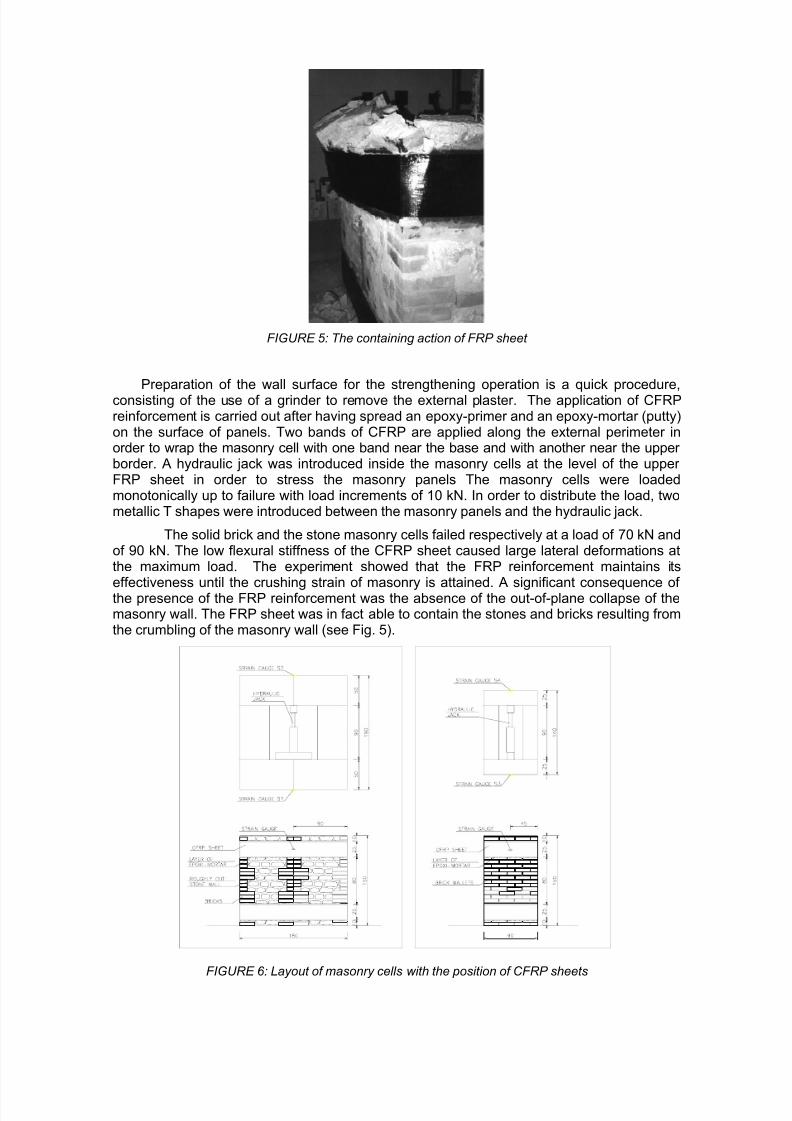
Several strain gauges were fixed along the FRP sheets in order to measure the stresstensile status of the composite (see Fig. 6). This allowed us to confirm that the FRPreinforcing technique carried out its strengthening action, as well as to measure the degreeof utilization of the FRP. However, the abrupt variation in curvature occurring at the four angles of the masonry cells should be avoided. CFRP sheets have a high degree of weakness due to the onset of stress at right angles to the fibers. In this case, the problemwas partially solved thanks to the introduction of steel L shapes characterized by a radius of curvature of 2 cm.
Moreover, the use of L shapes with a height greater than the height of the CFRP sheetcauses a better distribution of compressive stresses on the masonry surface and in partavoids the masonry crushing at the angles of the cell (see Fig. 7).
FIGURE 7: The use of metallic L shapes in order to distribute stresses along the masonry
However the effect of using CFRP strengthening on corrosion confinement of steelelements should be studied and carried out with care. Many researchers have attempted tocharacterize the performance of corrosion damaged RC structures reinforced with CFRPsheets, showing the importance of the resin layer in separating steel and carbonreinforcements.
CFRP sheet
CFRP bar
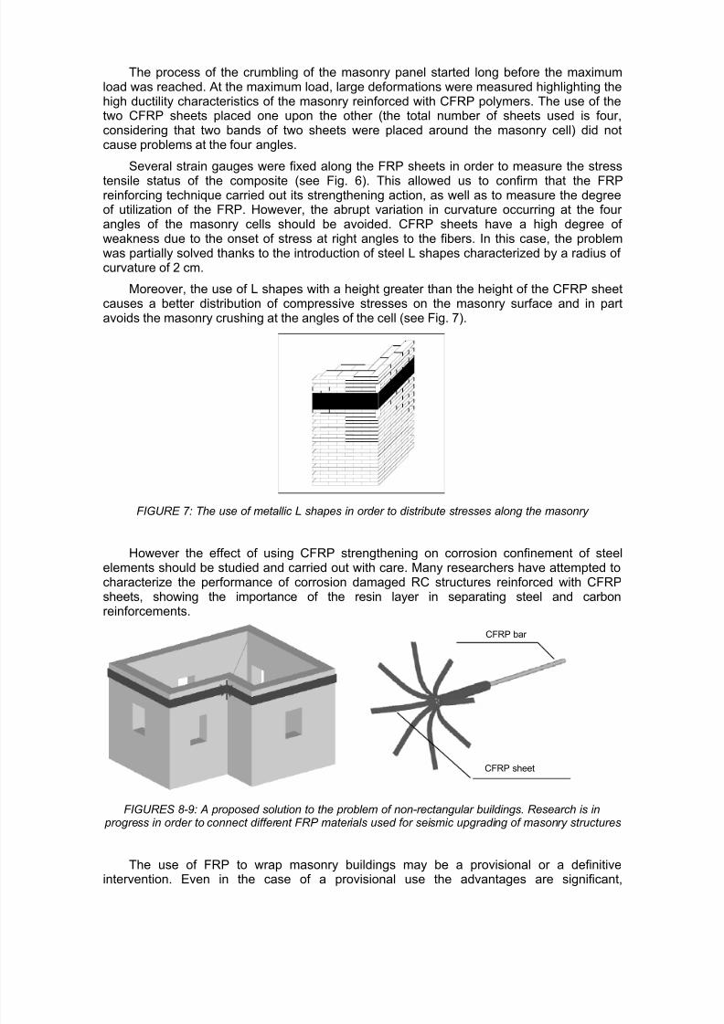
FIGURES 8-9: A proposed solution to the problem of non-rectangular buildings. Research is in progress in order to connect different FRP materials used for seismic upgrading of masonry structures
The use of FRP to wrap masonry buildings may be a provisional or a definitiveintervention. Even in the case of a provisional use the advantages are significant,

7/30/2019 w10_borri New Materials for Strengthening and Seismic Upgrading Interventions FRP
http://slidepdf.com/reader/full/w10borri-new-materials-for-strengthening-and-seismic-upgrading-interventions 11/23
considering the rapidity with which it can be realized and the possibility of putting in securitydamaged masonry structures.
This technique may also be applied to non-rectangular structures. In these cases apossible solution is shown in Figures 8 and 9: a tendon composed of a CFRP bar (or ametallic one) is connected, by means of FRP strips, to the external FRP band in order toavoid debonding of the FRP sheet from the surface of the masonry structure. The connection
of CFRP bars to orthogonal sheets is now studied and preliminary results indicate itseffectiveness.
4.2 Shear reinforcement of masonry walls
Various kinds of intervention may be carried out to upgrade a wall. Currently, the mostwidespread technique consists of injecting lime-based grouts or fixing a metal net onmasonry surfaces under a concrete jacket. Borri, Corradi and Vignoli applied this techniquein order to upgrade several two-leaf and three-leaf walls. Other authors applied differenttechniques in order to seismic upgrade masonry panels [15] [16]. The results substantiallyshowed that while the injection technique can be effective when used as a repair technique,its adoption as a preventive measure necessitates a previous, careful analysis of themasonry texture and of its characteristics, in order to understand if the grout can, in effect,penetrate it well.
The use of FRP on similar walls was also studied. These walls were tested under diagonal compression and shear-compression. This involved the use of panels of variousdimensions. Five of ten panels were tested without strengthening, to determine themechanical characteristics of the masonry. The remaining five was consolidated respectivelywith monodirectional carbon fibers and monodirectional fiberglass. Strengthening with onesheet of monodirectional carbon fiber or fiberglass was carried out on both sides of thepanel, following the scheme presented in Figure 11. Due to the great irregularity in themasonry texture, the strengthening of the panels was carried out only after spreading a layer of cement based mortar to create a sufficiently plane, uniform surface on which thecomposite was then applied. The mortar used was placed directly on the masonry once the
original plaster had been removed
4.2.1 Diagonal Compression Tests
The diagonal compression test was carried out on panels 120 x 120 cm (according to ASTM specifications [17]) with cross-sections of varying thickness, depending on thestructure on which the intervention was affected. The aim of this test was to determine theshear-strength and the shear elastic modulus of the masonry. The panel was isolated fromthe rest of the masonry by means of the diamond wire cutting technique in order to leave itundisturbed (see Fig. 10).
120
1 2 0
P
D1
P
D2
FIGURE 10: Layout of the diagonal compression
test FIGURE 11: A masonry panel strengthened with
CFRP

7/30/2019 w10_borri New Materials for Strengthening and Seismic Upgrading Interventions FRP
http://slidepdf.com/reader/full/w10borri-new-materials-for-strengthening-and-seismic-upgrading-interventions 12/23
The test mechanism was composed of a set of metallic elements joined together toobtain a closed system. The stress was applied to the panel by means of a compressionload, coplanar to the panel itself and directed along one of its two diagonals. A jack placedalong the diagonal, external to the panel, was positioned between two metallic elementswhich permitted it, on the one hand, to act directly on an edge of the panel, while at the sametime to remain rigidly connected to an analogous metal element located along the oppositeedge. In correspondence to this edge the situation was analogous, except for the absence of
the jack: the two most external metal elements were rigidly connected by means of two steelrods of equal length to allow a uniform distribution of the load throughout the thickness of thepanel. The panel was instrumented on both sides with LVDT inductive transducers tomeasure the deformations occurring along the four diagonals. It was therefore possible toacquire the strains during the test as a function of time and the value of the load applied tothe jack. The test procedure consisted of loading and unloading cycles of increasingmaximum values, until the point of failure was reached. The load was applied following aseries of equal couples of cycles, with increases of 10 kN, up to the point of failure. In thecase of strengthened panels with failure loads greater than 80 kN, the interval between onecouple and the other was increased to 20 kN.
The analysis of the results of the diagonal compression tests is the object of
interpretation differing from Author to Author. This test was introduced to simulate a pureshear stress state. In these conditions the Mohr circle of the stress state is centered in the
origins of σ−τ axes and the value of the average shear stress τ , equal to the principal tensile
stress σΙ, is given by:
2 A
P I == σ τ
(2)
in which P is the diagonal compression load, A the cross-horizontal section of the panel
and τ is the average shear stress in the panel. According to this interpretation, which is thatmore frequently used [18], the shear strength is evaluated as:
2
max
A
P k =τ
(3)
Where P max is the maximum compression load applied during the diagonal compressiontest and
k τ is the average shear strength.
Both the shear modulus of elasticity G1/3 and the shear strain γ1/3 are measured at 1/3maximum load. The value of shear modulus of elasticity G1/3 is given by the slope of secant
line matching the shear stresses τi and τ1/3 .
3/1
3/1
3/1
γ
τ τ iG−
= (4)
Where τi is the shear stress at 0=γ , τ1/3 is the shear stress at 1/3 maximum load, 3/1γ
is the shear strain at 1/3 maximum load.
t c ε ε γ += (5)
Wheret ε and
cε are the average normal strain of the four diagonals in compression
and in traction.
4.2.2 Shear-Compression Tests
The shear-compression test was carried out on panels of dimension 180x90 cm, with amaximum section thickness of 65 cm. Eight transducers were placed along the diagonals of
the four square surfaces, obtained by subdividing each of the two vertical sides of the panelin two equal parts. Three additional transducers were positioned on each side - to measuretransversal movements - along the centerline, and at the top of the panel. Two other transducers were placed vertically at the edge of one side of the panel to measure eventual

7/30/2019 w10_borri New Materials for Strengthening and Seismic Upgrading Interventions FRP
http://slidepdf.com/reader/full/w10borri-new-materials-for-strengthening-and-seismic-upgrading-interventions 13/23
rotations at the top of the panel. The shear-compression tests, analogous to the diagonalcompression tests, were designed to determine the shear strength and shear elastic moduluscharacteristics of the masonry. The test consists of a monotonic loading up to the point of failure, under a state of constant compression for the duration of the test. The compressionstress was applied up to a vertical stress of 0.3 MPa.
The horizontal shear force was applied by two steel rods, which acted on a special metal
element positioned at the centerline of the panel. This element consists of two C shapes,coupled with plates welded to the webs, whose function is to distribute the concentrated loadthroughout the panel thickness. An oleo-dynamic jack is interposed between an I shape,used as a contrast element (positioned parallel to the height of the panel at a lateral openingin the masonry), and a metal beam similar to that at the centerline of the panel. The actuator loads, on one side, the I shape, whose job is to distribute the load concentrated at the baseand at the top of the opening, and on the other side, the metallic element to which areattached the two steel ties which thus result in tension.
The upper part of the panel was contrasted by means of a couple of 100 kN jackspositioned horizontally, in order to avoid flexural failure mechanisms. This couple alsoallowed measurement of the horizontal reaction at the top of the panel. The condition of double bending results only in the hypothesis that the upper edge is prevented fromtranslating and rotating.
This condition is in part supplied thanks to the presence of the jack couple, blocked onthe load assigned, and of the horizontal plate placed on the panel. Nevertheless, the stiffnessof the apparatus at the top of the panel and the vertical rods is not sufficient to act as aperfect constraint, as requested. This allowed a lack of symmetry in the distribution of theshear stresses between the upper and lower halves of the panel, which was taken intoaccount during the elaboration of the data.
In addition to the displacements of the sixteen inductive transducers, measurementswere also acquired of both the time and the pressure in the two vertical and three horizontal jacks, for a total of twenty-one channels of acquisition.
During the shear-compression test, the failure condition occurs when the principaltensile stress σI in the center of the panel is equal to the tensile strength of the masonry. Inorder to evaluate the shear strength of the masonry, the well-known Turnsek and Cacovicformulation is assumed:
k
k bτ
σ τ τ 0
max1+=
(6)
Wheremax
τ is the shear strength,k τ is the shear strength without normal stress and
0σ
is the compressive stress. b is a shape factor that takes into account the variability of theshear stresses on the horizontal section of the wall. The Italian Standards and the well-
known POR method assume this parameter equal to 1.5.
Scheme 1 Scheme 2
δ δ
0.9 T
T
iu
iu
K 0
δδ δ
FIGURE 12: The two schemes used for elaboration of the data of the shear-compression
test.
FIGURE 13: Procedure applied to calculate δ E

7/30/2019 w10_borri New Materials for Strengthening and Seismic Upgrading Interventions FRP
http://slidepdf.com/reader/full/w10borri-new-materials-for-strengthening-and-seismic-upgrading-interventions 14/23
With regard to the Scheme 1, shown in Figure 12, the shear modulus of elasticity G isgiven by:
+==2
02.1
12.1
9.0
1
d
h
E
G
GA
h
T K iu
E δ (7)
Where:
T iu is the maximum shear load in the lower halve,
h is the height of the lower halve panel,
E is the Young’s modulus of elasticity obtained from compression tests,
d is the width of the panel,
δE is evaluated as showed in Figure 13,
A is the horizontal cross-section of the panel.
4.2.3 Evaluation of the Results
Eight, of the ten panels, were double-leaf masonry walls, made of weakly connectedroughly cut stone, while two were of solid brick. The cross section thickness of the panels instone also turned out to be more or less constant with values varying from 48 to 57 cm, whiledifferences of properties were noted in the mortars (all lime-based), depending also on theperiod in which the building was constructed.
For the diagonal compression tests the interpretative models of structural behavior arethe classic ones [17], while for the shear-compression tests Sheppard's model [19] is used,taking into account hypothesis and interpretative choices as in [20].
The results of shear-compression tests (see Tab. 8) show an increase in the strength, τk,of the strengthened panels, relative to those non-strengthened, of approximately 55%,
independent of the type of fibers used. This essentially depends on the particular modality of failure, which did not involve the crisis of the composite, except at a limited area on some of the panels. In fact, the fibers remained attached to the cement-based mortar (used to createa uniform surface on which the FRP was applied), which in turn had detached from themasonry. Therefore, since the state of fiber stress was well below its failure level, it was onlymarginally engaged. For this reason, no difference resulted from the use of carbon fibers or fiberglass. However, in the successive diagonal compression tests the layer of mortar wasreplaced by a thinner layer of epoxy putty, which bonded more efficiently with the masonrysubstrate and determined a better utilization of the fibers, which did not detach until themasonry-composite system failure was reached.
TABLE 8: Results of the shear compression tests (static scheme 1: double fixed end; static scheme 2:fixed end and fixed end with determinate stiffness to 2 D.O.F.: horizontal translation and rotation in the
panel’s plane)
Index Code Strengthtechnique
Texture Section[cm]
P max
[kN] τ max
[MPa]
G[MPa] Scheme 1
G[MPa] Scheme 2
τ k
[MPa] b=1.50
B-T-04-OR None double-leaf roughly cut stonemasonry
48 180.70 0.219 546 328 0.130
B-T-05-FC CFRP double-leaf roughly cut stonemasonry
48 241.40 0.352 467 771 0.262
V-T-06-FV GFRP double-leaf roughly cut stonemasonry
48 231.30 0.334 245 249 0.245
P-T-15-OR None double-leaf roughly cut stone
masonry
48 100.40 0.172 216 - 0.136

7/30/2019 w10_borri New Materials for Strengthening and Seismic Upgrading Interventions FRP
http://slidepdf.com/reader/full/w10borri-new-materials-for-strengthening-and-seismic-upgrading-interventions 15/23
TABLE 9: Results of the diagonal compression tests.
Index Code Strengthtechnique
Texture Section[cm]
P max
[kN] τ k
[MPa]
G1/3
[MPa] γ 1/3
B-D-02-OR None one-leaf solid brick masonry 48 34.31 0.069 131 0.136B-D-03-FC CFRP one-leaf solid brick masonry 48 188.25 0.373 100 1.240G-D-11-OR None double-leaf roughly cut stone masonry 57 51.14 0.053 26 0.643
G-D-12-FC CFRP double-leaf roughly cut stone masonry 57 121.53 0.127 55 0.699P-D-13-OR None double-leaf roughly cut stone masonry 48 47.66 0.059 37 0.533P-D-14-FC CFRP double-leaf roughly cut stone masonry 48 141.61 0.173 117 0.497
0,00
0,05
0,10
0,15
0,20
0,25
0,30
0,35
0,40
0,0 1,0 2,0 3,0 4,0 5,0 6,0 7,0 8,0 9,0 10,0 11,0 12,0 13,0 14,0
γ x10e-3
S h e a r s t r e s s
[ M
P a ]
P-D-14-FC
G-D-11-OR
G-D-12-FC
P-D-13-ORB-D-02-OR
B-D-03-FC
FIGURE 14: Diagonal compression tests (gray lines: panels un-strengthened, black lines: panelsstrengthened with CFRP)
For diagonal compression tests, the use of epoxy putty in place of the cement-basedmortar determined an increase in shear strength of 240% compared to the non-strengthenedpanels. The masonry panel(code: B-D-02-OR), made of solid brick, presented a notably lowfailure stress of 0.069 MPa for the non-strengthened panel (see Tab. 9). Instead, themasonry-composite system of the panel strengthened with CFRP was shown to be veryresistant, with a failure stress of 0.373 MPa, thanks to the effect of confinement the fibersinduced on the masonry as well as to the presence of diatons, which acted as connectors. At
the failure load, the masonry fractured in compression, determining the expulsion of smallportions of brick from the panel, while the CFRP applied on a thin layer of epoxy puttyremained attached to the panel
The results for the shear elastic modulus G, measured following ASTM specifications at1/3 maximum load, were between 26-131 MPa for non-strengthened panels subjected todiagonal compression tests. Strengthening by means of fibers in composites does not resultin sharp increases in the shear elastic modulus: panels for diagonal compression tests,strengthened with carbon fibers, resulted stiffer, however, with average values of approximately 250%, while in one case there was a practically negligible increase. Thecomposite does not alter the static scheme of the structure nor does it determine major redistribution of stiffness (above all for fiber glass), but mainly shows up as an increase in theshear strength of the masonry by means of the mobilization of the fiber traction strength.
Comparisons in the behavior of panels subjected to diagonal compression tests are
shown on a τ−γ graph in Figure 14. Both the similarity in behavior among the non-strengthened panels, as well as the significant increase in shear strength of the strengthened

7/30/2019 w10_borri New Materials for Strengthening and Seismic Upgrading Interventions FRP
http://slidepdf.com/reader/full/w10borri-new-materials-for-strengthening-and-seismic-upgrading-interventions 16/23
panels, can be noted. This latter aspect turns out to be particularly evident for the injectedpanels.
4.3 Seismic upgrading of masonry vaults or arches
In general vaults adapt well to variations in geometrical configuration, being able todistribute deformations along mortar joints without significant cracks forming and a behavior
that may be partly compared to that of the isostatic structures. The onset of damagingkinematic motions is not so much conditioned by the exceeding of the limits of strength of thematerials, as by the incapacity of the constraints to counteract the actions transmitted by thevault. In many cases the structural damage is therefore due to indirect causes. Thepressures exerted against the walls produce the reciprocal moving away of the imposts or springers, something which generally happens through a rotation of the external walls andsagging of the keystone. A somewhat frequent type of damage is distinguished by theformation of cylindrical hinges in the sections at the haunches to the extrados and at theintrados or soffit crown, where the concentration of stress leads to the plasticitation of thematerial and the consequent accentuation of deformation. Rotation of the voussoirs aroundthe haunches results in their detachment from the walls and the formation of cracks, throughwhich the filling material “crumbles”. Worsening of damage may be effectively countered with
suitable work, while the correction of the deformative state is more difficult despite the factsome valid strengthening techniques have as their operating strategy the restoring of theoriginal geometrical configuration. To recover the profile of the crown, it is generallynecessary to integrate the brickwork bond in order to compensate for the aperture caused bythe moving away of the imposts. Other causes of damage are due to the differentiated yieldsof the support, which in the case of cross vaults are caused by localized thrust near theimposts. The sagging effect is shown in Figure 15, where the cracks around the intrados atcrown are highlighted as well as at the extrados of the haunches opposite the corner involved in the shift.
4.3.1 Aseismic work with composite materials
This section gives the theoretical results and details of some work a site regarding the
aseismic strengthening of historical vaulted structures. In particular, a working method isproposed based on the use of sheets of composite material (FRP), the outlines of whichhave been explained by the same Authors in previous publications [21] [22] and by other Authors in [23] [24]. The aim was to study, design and accomplish aseismic protectivesystems for vaulted structures without altering the static set-up. The reason was to maintainthe capacity of the vaults to adapt to the settling of the load-bearing structure and to thedeformation induced by seismic stress. It must be specified, however, that the proposed workcannot be applied to all situations; the type of fault shown by the vault being of crucialimportance:
• Statically acceptable configuration: the profile of the vaulted structure is sufficient to limitthe line pressures with an adequate margin of safety. The local cracks do not jeopardize
overall operation, in that the vault is, in short, still structurally efficient.
• Statically unacceptable configuration: the deformations of the profile or profiles areaccentuated to the extent that the static of the vaulted structure in critical conditions; inthe case of an arched structure, this is equivalent to the risk of collapse.
The proposed method of operation is referred to the first case as well as to the situationsin which the vaulted structure has no damage. Other indications which influenced the projectdecision and which led to cladding the extrados with FRP sheets were as follows:
• The need to work on the extrados avoiding any percolation of material (e.g. due to thepresence of frescoes);
• The need to avoid introducing connections between the vault and the outer wall(reinforcing injections) in order not to alter the static operation of the vault;

7/30/2019 w10_borri New Materials for Strengthening and Seismic Upgrading Interventions FRP
http://slidepdf.com/reader/full/w10borri-new-materials-for-strengthening-and-seismic-upgrading-interventions 17/23
• The need not to create superstructures over the vault aimed at relieving it of its staticfunction;
• The need to replace the supports, if present, with similarly effective devices (low brickwalls).
Regarding the thrusts, which the vault exerts on the walling, it should be noted that thecladding of the extrados with the fibers does not substitute classic operations (tie-rods on thehaunches or abutments). There is, however, an exception to this rule if it is possible toencircle the vaulted premises externally at the height of the centre of thrust; a somewhat rarepossibility due to the difficulties tied to a historical site. The following summarizing chart isgiven to describe the efficacy of the cladding with FRP sheets and the way in which their effect is combined with that of the tie-rods. The chart in Figure 15 presents some states of damage related to the mechanism of damage that caused it in the case of vaults with or without tie-rods. The forces indicate the prevailing effect of the earthquake responsible for amplifying the vertical loads and of appearance of horizontal forces in proportion to theweight of the vault and of superstructures. This stress obviously depends on the magnitudeof the seismic accelerations at the base of the piers.
Un-strengthened vault
FRP strengthening
FRP strengthening System n.2
Metal tiestrengtheni
FRP and metal tiestrengthening
FRP and metal tie strengt.System n.2
A
B
C
1 2 3 4
FIGURE 15: Collapse mechanisms for different strengthening systems
The bottom two lines show the fault in the presence of just and with sheets plusanchoring devices. It should be specified that the extrados sheets are only effective asaseismic protection with regard to important movements of the profile of the arch on whichthey rest.
4.3.2 Project criteria for work on cross vaults
The following overall indications may be given with regard to the design and the siteoperations. The first “shoot” of concrete should be high enough to reach the area of the archhaunches. The height of the closing jet and therefore the height of the slab are just above thehaunches. It is advisable to use a double layer of sheets. A third layer is recommended onhalf-brick vaults with over 6-meter span. The ideal width for the outer sheets is 25 cm. A rod
FeB44K-φ24 with threaded head is recommended for the anchorage. Once the fibers havebeen laid, a plug is made at the cross between the median lines of the two sheets with acommon cutter. A hole of at least 4 cm of diameter is made and should be carefully cleaned. A suitable grout for the particular masonry is injected and then the rod or bar is inserted.

7/30/2019 w10_borri New Materials for Strengthening and Seismic Upgrading Interventions FRP
http://slidepdf.com/reader/full/w10borri-new-materials-for-strengthening-and-seismic-upgrading-interventions 18/23
After a few days the head of the bar is fixed to the slab by means of a nut and load-distributing wedge. Torque wrenches are not required (see Figures 16-17).
FIGURE 16: Position of FRP on the Assisi TownHall cross vaults
FIGURE 17: Intervention is completed withhollow-brick walls
4.3.3 A study case: seismic strengthening of the vaults of the Town Hall of Assisi
The design criteria described above are applied here to the vaults of the Town Hall of Assisi. This important complex, which covers a vast portion of the main square of Assisi,consists of many building units built at different times and joined together over the centuries.Unlike past work, which altered the spatial layout and therefore the actual load-bearingstructures, this work was mostly concerned with seismic strengthening. To achieve this aim,an attempt was made to avoid any work, which would be particularly traumatic for thestructure and in particular for the vaults, favouring the introduction of aseismic protectivedevices. Even though the complex is not organised according to what would today be called
a correct engineering design logic (the various parts have been aggregated in a often chaoticmanner), the current static set-up, as often happens in buildings in historical centres, isbasically not negative thanks to the capacity of the walls to adapt to the different structuralsituations. In other words, the equilibrium that the structure has reached may be consideredstatically satisfactory, even if poor from an aseismic point of view. The building containsvaults of different types and different eras with problems tied to the bad state. The mostfrequent type is cross vaults, but there are also barrel vaults with lunettes. In the top floor rooms there are Welsh cavetto vaults both with half-brick thickness and with bricks laid onedge. Analysis of the damage produced by the Umbria-Marche earthquake of 1997highlighted a particular weakness of the seismic actions on the brick-on-edge vaults and thehalf-brick vaults covering the reception rooms on the top floors. Less severe damage, but un-doubted worthy of aseismic engineering attention, was found on the cross vaults of the
ground floor rooms, while no particular structural problem was obvious on the massivevaulted structures of the underground floors. The considerable variability of the differenttypes of vaults in the complex, the presence of frescoed surfaces on the intrados of thevaults in the reception rooms and the particular site conditions resulted in a variety of structural situations for each of which ad hoc solutions were studied. Within this study,several cases are highlighted in this paper where the strengthening technique using sheetsof composite material seemed preferable to “traditional” methods. A brief description of thetype of vault and the damage is given for each work, followed by the criteria, which guidedthe project decision. Lastly, a list of the working stages is given with special attention paid tothe site measures made necessary for correct results.
4.3.4 Application of FRP to the extrados of half-brick cross vaults
The work involved removal of the support up to the haunches, where the bricks of thearched lintel are inserted into the outer wall. A layer of concrete was created above theseareas of insertion, with sufficient thickness to join the curvature of the outer arches of the

7/30/2019 w10_borri New Materials for Strengthening and Seismic Upgrading Interventions FRP
http://slidepdf.com/reader/full/w10borri-new-materials-for-strengthening-and-seismic-upgrading-interventions 19/23
vault with the area of the lintels. Since the vaults have frescoes on the intrados, a rheoplasticmortar with coarse sand as filler was used.
FIGURE 18: Primer application FIGURE 19: The fixing operation at the extradosof the vault
After having thoroughly cleaned (by sanding and water cleaning) and then leveled thesurface of the outer vault area, 4 bedding bands were created using suitable mortar. After thefew days required for curing of the mortar, the surface was prepared with a suitable primer and the first monodirectional layer of FRP was laid with epoxy-resin. A second layer was alsoprepared (see Figures 18-19).
The reason for this does not lie in the strength of the material (one layer is more thanenough in terms of resisting capacity), but in the greater reliability of the pack made up of twolayers, which is far less sensitive to local effects connected with the irregularity of the layingsurface. It should be noted, in fact, that despite careful preparation of the extrados of thevault, areas with abrupt variations in curvature may occur. In these cases experimental testsshowed high degree of weakness of the individual monodirectional sheet due to the onset of
stress at right angles to the fibers; the pack with two sheets instead proved far less sensitiveto this effect, also thanks to the imperfect alignment of the direction of the fibers and due tothe distribution effect exerted by a thicker layer of resin. After the sheets have been laid, asmall amount of concrete was cast over each lintel, onto which a steel plate fitted with awedge (also in steel) was placed (see Fig. 20). The latter was designed to house theanchoring rod, inserted diagonally, in order to reach the height of the springer. The work wascompleted in the traditional way with the construction of low hollow-brick walls, arranged at adistance apart equivalent to that of the overlaying hollow floor slab (approx 80-100 cm).
4.3.5 Application on FRP to the extrados of half-brick cloister vaults
The work involved four Welsh cloister vaults in as many rooms. The vaults only have adecorative function and the space separating them from the roof is simply a garret with just
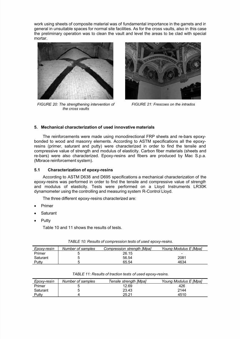
enough height to carry out routine maintenance. That is why the vaults do not have supportsbut just voussoirs, which have a modest bracing function in any case limited by theexcessively low profile. All the vaults were half a brick thick, even if an extensive portion inthe central part of one of them had bricks laid on edge (thickness 5 cm). It was probably areconstruction following a collapse. The greater constructional simplicity of the brick-on-edgevaults compared to the half brick ones may have justified the choice. The crack due to theUmbria-Marche earthquake in 1997 was particularly evident around the ribs. In all four caseshighly visible cracks had formed at the corners to the intrados where there were frescoes(see Fig. 21). There was more damage to the larger vaults and in any case the cracks hadoccurred over pre-existing fissures, symptom of an intrinsic weakness of this type, alsoobvious in static conditions. Damage to the top (at the crown) was only important in onecase, where there was sagging of a central longitudinal portion about 50 cm wide.
The work with FRP strips in these cases was quite easy due to the absence of fillingabove the vaults. Even the difficulties tied to the restricted working space were limited due tothe lightweight and relatively small size of the material used. This peculiarity of the cladding
7/30/2019 w10_borri New Materials for Strengthening and Seismic Upgrading Interventions FRP
http://slidepdf.com/reader/full/w10borri-new-materials-for-strengthening-and-seismic-upgrading-interventions 20/23
work using sheets of composite material was of fundamental importance in the garrets and ingeneral in unsuitable spaces for normal site facilities. As for the cross vaults, also in this casethe preliminary operation was to clean the vault and level the areas to be clad with specialmortar.
FIGURE 20: The strengthening intervention of the cross vaults
FIGURE 21: Frescoes on the intrados
5. Mechanical characterization of used innovative materials
The reinforcements were made using monodirectional FRP sheets and re-bars epoxy-bonded to wood and masonry elements. According to ASTM specifications all the epoxy-resins (primer, saturant and putty) were characterized in order to find the tensile andcompressive value of strength and modulus of elasticity. Carbon fiber materials (sheets andre-bars) were also characterized. Epoxy-resins and fibers are produced by Mac S.p.a.(Mbrace reinforcement system).
5.1 Characterization of epoxy-resins
According to ASTM D638 and D695 specifications a mechanical characterization of theepoxy-resins was performed in order to find the tensile and compressive value of strengthand modulus of elasticity. Tests were performed on a Lloyd Instruments LR30Kdynamometer using the controlling and measuring system R-Control Lloyd.
The three different epoxy-resins characterized are:
• Primer
• Saturant
• Putty
Table 10 and 11 shows the results of tests.
TABLE 10: Results of compression tests of used epoxy-resins.
Epoxy-resin Number of samples Compression strength [Mpa] Young Modulus E [Mpa]
Primer 5 26.15 -Saturant 5 56.54 2081Putty 5 65.54 4634
TABLE 11: Results of traction tests of used epoxy-resins.
Epoxy-resin Number of samples Tensile strength [Mpa] Young Modulus E [Mpa] Primer 5 12.69 426Saturant 5 23.43 2144Putty 4 25.21 4510

7/30/2019 w10_borri New Materials for Strengthening and Seismic Upgrading Interventions FRP
http://slidepdf.com/reader/full/w10borri-new-materials-for-strengthening-and-seismic-upgrading-interventions 21/23
5.2 Characterization of fibers
The CFRP sheets were characterized following ASTM D 3039 specifications. Theresults of the tests are reported in Table 12.
TABLE 12: Results of traction test carried out on CFRP samples (monodirectional sheets)
Number of samples
Failurestress[MPa]
Young modulus of elasticity E [MPa]
Failure stress(dry fiber thicknesst=0.165mm) [MPa]
Young modulus of elasticity E (dry fiber thicknesst=0.165mm) [MPa]
5 958 117855 3388 417624
6. Prospective of the experimental research
An analytical model suitable for design purposes is now developed for the prediction of the behavior of shear walls, masonry vaults and wood beams reinforced with FRP sheets.Based on the test results, it is possible to conclude that the application of externally bonded
carbon fiber sheets seems to be an effective seismic strengthening and repair procedure.However it will be necessary further research in order to determine the efficiency of theproposed intervention methods. In particular the long-term performance will be analyzed.
In order to verify the effective behavior of the composite reinforcements, a series of simple traction, compression and bond tests will be carried out on fiber, resin, masonry andwood test pieces. The results of these tests may be useful for numerical modeling in order tofind the appropriate parameters to use for analytical analyses.
7. Conclusions
Mechanical tests on the reinforced wood showed that external bonding of thin composite
sheets on the side loaded in traction of flexed wood parts produces very interesting effects.In the case of carbon fibers, which demonstrated to be the most performing ones, resultsshowed increases in flexural strength up to 90% compared to the results of un-strengthenedspecimens. Glass and, even more, aramidic fibers, produced smaller strength increases, butif taking into account its low price, glass fibers demonstrated to be very good candidates. Onthe other hand the Young modulus increase was not so high.
It has than been illustrated how it is possible to obtain an important increasing of thestiffness simply pre-loading the samples. Gluing the composite reinforcement during thewood pieces were under a bending load applied in the opposite direction than during thetests, produced a maximum stiffness increase as high as 80%, without affecting the sample'sstrength. But more tests should be necessary in order to better qualify such a behavior. The
used technique resulted easy and fast to realize, even if on in situ parts. In particular itdemonstrated to be very promising in many cases of old and historical structural wood partsrestoration.
The second part of the experimental work relates to a study on the seismic upgradingand repair interventions of masonry buildings, walls and vaults using externally bondedcarbon and glass fiber sheets.
Fiber wrapping of masonry buildings in FRP may inhibit the out-of-plane mechanisms of masonry walls and permits the transfer of seismic loads to the wall parallel to the direction of seismic action. This technique may be used for provisional or definitive interventions and itshows positive characteristics with regard to several aspects, such as the increase in ductilityof the masonry structure.
With regard to the shear strengthening of masonry panels with sheets of monodirectional carbon or glass fiber, the shear compression tests carried out on panels of varying dimensions have highlighted the fact that the interface between the panel and the

7/30/2019 w10_borri New Materials for Strengthening and Seismic Upgrading Interventions FRP
http://slidepdf.com/reader/full/w10borri-new-materials-for-strengthening-and-seismic-upgrading-interventions 22/23
mortar used as a base for the fibers was the weakest element in the system. When acement-based mortar was applied, failure resulted from the separation of the layer of themortar from the panel, with almost equal increases in strength and stiffness for both carbonfibers and fiberglass. The subsequent diagonal compression tests, carried out using carbonfibers on a thin layer of epoxy plaster applied directly on the surface of the panels,demonstrated greater increases in both strength and stiffness. Failure resulted, in the case of stone panels, from a separation of the two masonry leaf walls, while in the case of the panel
in brick diatons it resulted from the crushing of the bricks at high load values. For thismasonry texture a comparison of the results with those for non-strengthened panels givesvery high increases in shear strength. The application of this type of intervention resultedmore effective in the case of panels made of adequately connected masonry multiple-leaf walls or, as in the case of the brick panel, consisting of a single leaf masonry wall, so thatcrisis mechanisms due to bending moment and axial forces were avoided. Severalspecimens have been tested in the present study and an interesting increase in shear strength, shear elasticity and ductility was obtained.
The reinforcing of masonry arch bridges or vaults seems to be more efficaciouscompared to traditional reinforcing procedures. This technique was applied on a historicbuilding located in Assisi, Italy, and its effectiveness is now under laboratory-testing on full-
scale prototypes with dynamic and static loading tests up to collapse. In addition, theproblem of fixing the FRP sheet to the masonry structure was studied, in order to avoiddebonding problems.
Acknowledgements
This paper is partially based on the results carried out by the SGM and Tec-Innlaboratory located in Perugia. Thanks also go to Mac S.p.A. for technical assistance duringthe strengthening operations.
8. References
[1] Rubinsky, I. A. and Rubinsky, A. (1954). A preliminary investigation of the use of fibre-glass prestressed concrete, Mag. Concr. Res., 6(17), 71-78.
[2] Kaifasz, S. (1960). Some tests on beams prestressed by fibre-glass cords, Mag.Concr. Res., 12(35), 91-98.
[3] Meier, U. (1987). Proposal for a carbon fibre reinforced composite bridge across theStrait of Gibraltar at its narrowest site, Inst. Mech. Engrs., 201(B2), 73-78.
[4] Fujisaki, T., Matsuzaki, Y., Seijima, K. and Okamura, H. (1987). New material for reinforced concrete in place of reinforcing steel bars, IABSE Symp., ConcreteStructures of the Future, Paris, France, 425-432.
[5] Saadatmanesh, H. and Ehsani, M. (1989). Application of fiber-composites in civilengineering, Structures Congress '89, ASCE, 526-535.
[6] Ranisch, E. H. and Rostasy, F. S. (1986). Bonded steel plates for the reduction of fatigue stresses of coupled tendons in multispan bridges, Adhesion betweenpolymers and concrete, RILEM, Chapman and Hall, London, England, 561-570.
[7] Triantafillou, C. T. and Deskovic, N. (1991). Innovative Prestressing with FRPsheets: mechanics of short-term behavior, Jour. of Eng. Mech., 117(7), 1652-1673.
[8] Plevris, N. and Triantafillou, T. C. (1992). FRP-Reinforced wood as structuralmaterial, Jour. of Mat. in Civil Eng., 4(3), 300-317.
[9] Giordano, G. (1964). La moderna tecnica delle costruzioni in legno, Hoepli, Milano.
[10] UNI 9091/2, Legno: Determinazione dell’umidità. Metodo per pesata, April 1987.

7/30/2019 w10_borri New Materials for Strengthening and Seismic Upgrading Interventions FRP
http://slidepdf.com/reader/full/w10borri-new-materials-for-strengthening-and-seismic-upgrading-interventions 23/23
[11] UNI ISO 3132, Legno: determinazione della resistenza a compressioneperpendicolare alla fibratura, April 1985.
[12] UNI ISO 3349, Legno: determinazione del modulo di elasticità a flessione statica,Oct 1984.
[13] Di Tommaso, A. and Barbieri, A. (1999). Evoluzione delle tecniche per ilmiglioramento sismico di torri e campanili: impiego degli FRP materials, International
Workshop Assisi 99, April 22-24, 1999, Assisi (Pg), 295-308.
[14] Avorio, A., Borri, A., Corradi, M. and Celestini, G. (1999). Miglioramento sismico:sperimentazione e analisi sull’utilizzo dei materiali compositi nelle costruzioni inmuratura, L’Edilizia, De Lettera ed., 9-10 sept.-oct., XIII, Milano, 60-71.
[15] Drdacky, M., Lesak, J. and Avramidou, N. (2002). Behaviour of masonry wallsstrengthened against seismic effects by yarn composite strips or geo-nets mountedon their surface, 1st International Conference on Vulnerability of 20th CenturyHeritage to Hazards and Prevention Measures, CICOP, Rhodes, April, 3-5.
[16] Avramidou, N. (2000). Ricerca sperimentale sulle tecnologie di ripristino/rinforzosismico di elementi tecnici, per mezzo di placcaggi realizzati con tessuti strutturali,
5th
Inter.tional Congress on Restoration of Architectural Heritage, Firenze 2000,Sept.17-24.
[17] ASTM E 519-81 (1981). Standard Test Method for Diagonal Tension (Shear) inMasonry Assemblages, American Society for Testing Materials.
[18] Chiostrini, S., Galano, L. and Vignoli, A. (2000). On the determination of strength of ancient masonry walls via experimental tests, 12th World Conf. on EarthquakeEngineering, cd-rom, Auckland, New Zealand, Paper No. 2564.
[19] Turnsek, V. and Sheppard, P. F. (1980). The shear and flexural resistance of masonry walls, Research Conf. on Earthquake Engineering., Skopje.
[20] Borri, A., Corradi, M. and Vignoli, A. (2000). Il comportamento strutturale della
muratura nelle zone terremotate dell’Umbria: alcune sperimentazioni, IngegneriaSismica, Patron Ed., XVII, n.3, sept.-dec. 2000, Bologna, 23-33.
[21] Borri, A., Avorio, A. and Bottardi, M. (2000). Theoretical Analysis and a case study of historical masonry vault strengthened by using advanced FRP. 3rd Inter. Conf. Advanced Composite Materials in Bridge and Structures, August 15-18, Ottawa-Canada, 577-584.
[22] Avorio, A., Barbieri, A., Borri, A., Corradi, M. and Di Tommaso A. (2001).Comportamento dinamico di volte in muratura rinforzate con FRP-materials: primirisultati, X Conv. Naz.le L’ingegneria Sismica in Italia, ANIDIS, CD rom, Potenza, 9-13 Sept. 2001.
[23] Faccio, P. and Foraboschi, P. (2000). Experimental and Theoretical Analysis of Masonry Vaults with FRP Reinforcements, 3° International Conference on AdvancedComposite Materials in Bridges and Structures, August 2000, Ottawa, Canada, 629-636.
[24] Valluzzi, M.R., Valdemarca, M. and Modena, C. (2001). Experimental analysis andmodeling of brick masonry vaults strengthened by FRP laminates, ASCE J. of Composites for Construction. August, 2001.
![ZZZ ]LDUDDW FRP - ziyaraat.netziyaraat.net/booksTareekh/MolaAliMadinayMayPacheesSaal.pdf · 3uhvhqwhge\zzz ]lduddw frp. 3uhvhqwhge\zzz ]lduddw frp. 3uhvhqwhge\zzz ]lduddw frp](https://static.fdocuments.in/doc/165x107/5e045b61dc086d0f1330bd6d/zzz-lduddw-frp-3uhvhqwhgezzz-lduddw-frp-3uhvhqwhgezzz-lduddw-frp-3uhvhqwhgezzz.jpg)