application note: My first projet with AC500 ECo Plc
20
Application Note AC500 eCo PLC – First Project LVD-EOTN112U-EN REVA Page 1 of 20 1 Introduction: This application note shows you step-by-step to create a basic PLC program with ABB eCo PLC using Automation Builder software tool. It also guide you to create hardware configuration, program the PLC and go online with PLC. 2 Objective: In this application example, we use AC500 eCo PM564 ETH CPU with digital input simulator. This PLC will connect to PC with Ethernet connection. Equipment list for this application note: Description Quantity PM564 ETH CPU 1 PC with Automation Builder V1.0 or later software installed 1 Power Supply 120vac in/24vdc out, 1.25A 1 CAT5 Ethernet patch cables 1
Transcript of application note: My first projet with AC500 ECo Plc
Application Note
AC500 eCo PLC – First Project
LVD-EOTN112U-EN REVA Page 1 of 20
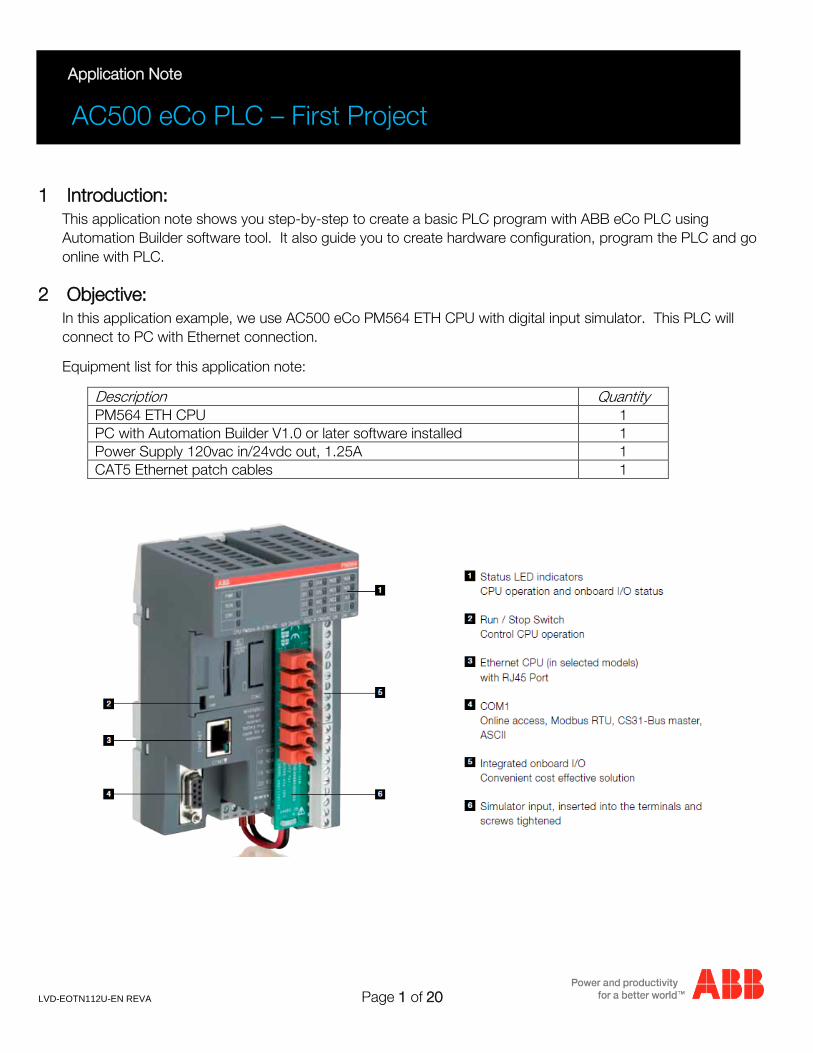
1 Introduction: This application note shows you step-by-step to create a basic PLC program with ABB eCo PLC using Automation Builder software tool. It also guide you to create hardware configuration, program the PLC and go online with PLC.
2 Objective: In this application example, we use AC500 eCo PM564 ETH CPU with digital input simulator. This PLC will connect to PC with Ethernet connection.
Equipment list for this application note:
Description Quantity PM564 ETH CPU 1 PC with Automation Builder V1.0 or later software installed 1 Power Supply 120vac in/24vdc out, 1.25A 1 CAT5 Ethernet patch cables 1
LVD-EOTN112U-EN REVA Page 2 of 20
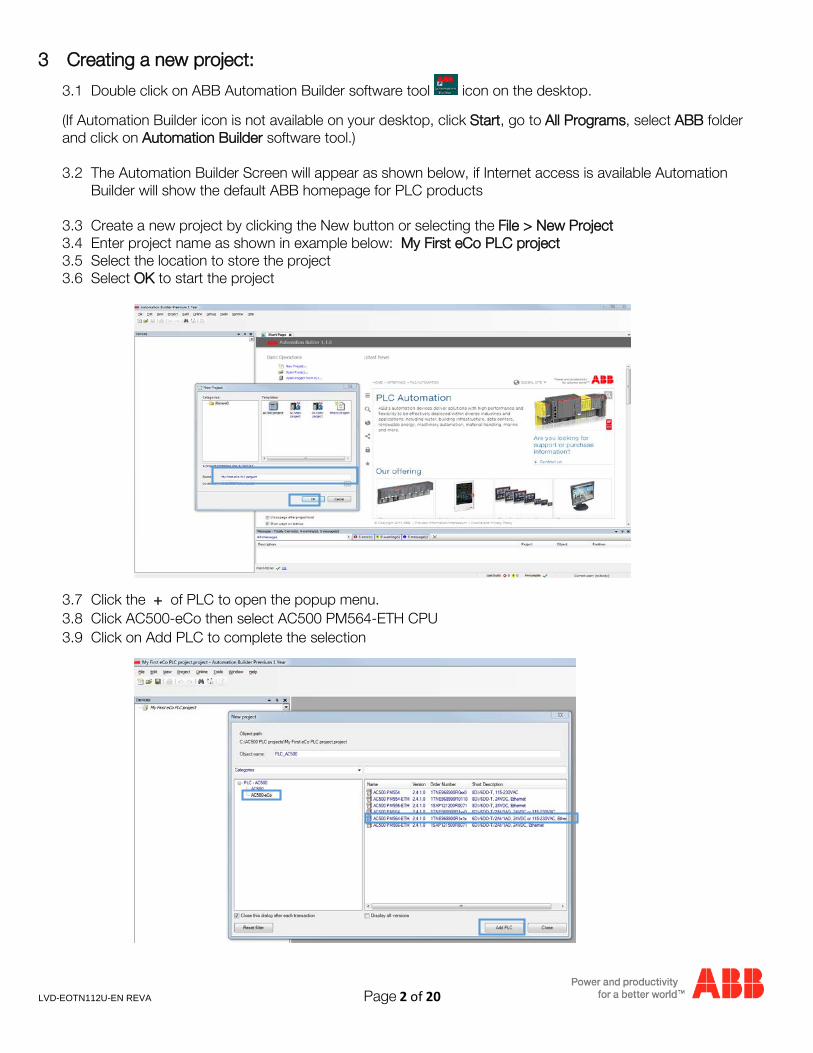
3 Creating a new project:
3.1 Double click on ABB Automation Builder software tool icon on the desktop.
(If Automation Builder icon is not available on your desktop, click Start, go to All Programs, select ABB folder and click on Automation Builder software tool.) 3.2 The Automation Builder Screen will appear as shown below, if Internet access is available Automation
Builder will show the default ABB homepage for PLC products
3.3 Create a new project by clicking the New button or selecting the File > New Project 3.4 Enter project name as shown in example below: My First eCo PLC project 3.5 Select the location to store the project 3.6 Select OK to start the project
3.7 Click the + of PLC to open the popup menu. 3.8 Click AC500-eCo then select AC500 PM564-ETH CPU 3.9 Click on Add PLC to complete the selection
LVD-EOTN112U-EN REVA Page 3 of 20
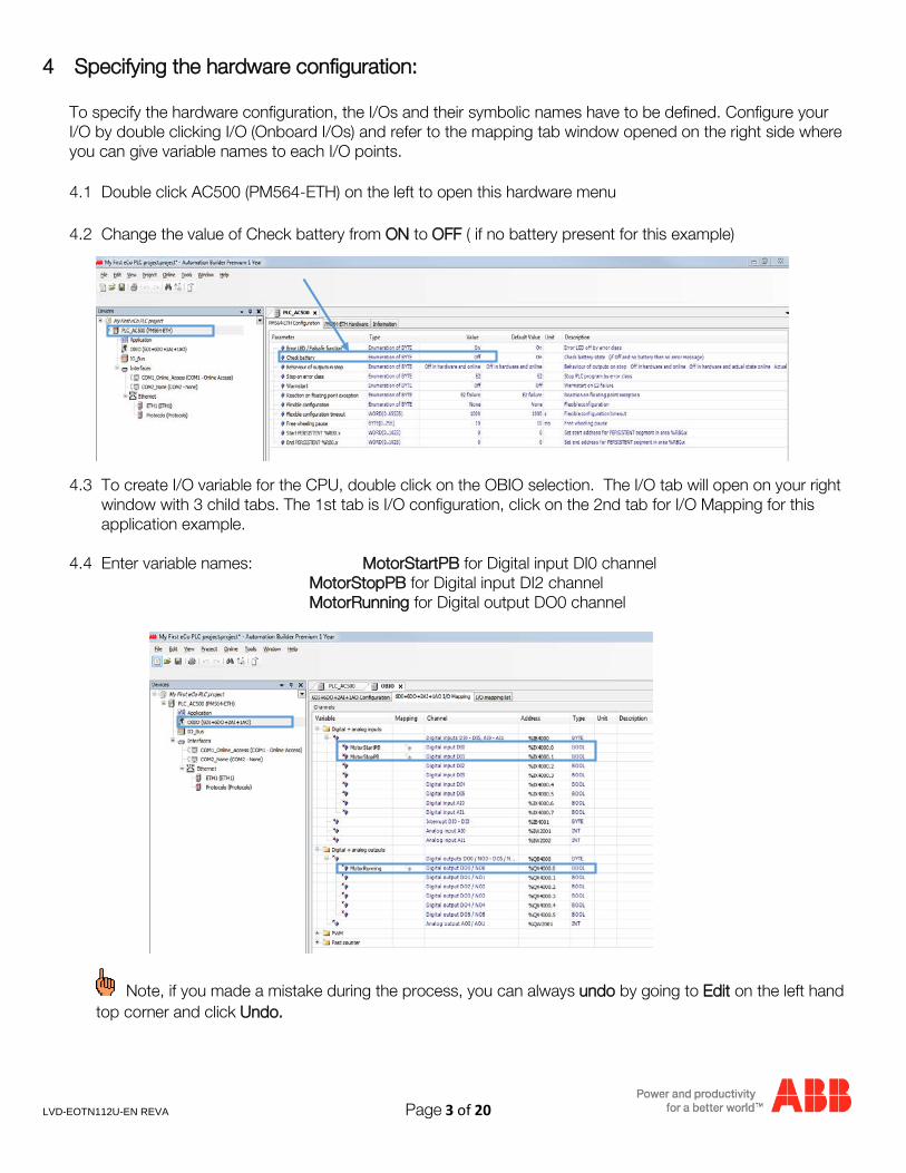
4 Specifying the hardware configuration:
To specify the hardware configuration, the I/Os and their symbolic names have to be defined. Configure your I/O by double clicking I/O (Onboard I/Os) and refer to the mapping tab window opened on the right side where you can give variable names to each I/O points. 4.1 Double click AC500 (PM564-ETH) on the left to open this hardware menu
4.2 Change the value of Check battery from ON to OFF ( if no battery present for this example)
4.3 To create I/O variable for the CPU, double click on the OBIO selection. The I/O tab will open on your right window with 3 child tabs. The 1st tab is I/O configuration, click on the 2nd tab for I/O Mapping for this application example.
4.4 Enter variable names: MotorStartPB for Digital input DI0 channel MotorStopPB for Digital input DI2 channel MotorRunning for Digital output DO0 channel
Note, if you made a mistake during the process, you can always undo by going to Edit on the left hand top corner and click Undo.
LVD-EOTN112U-EN REVA Page 4 of 20
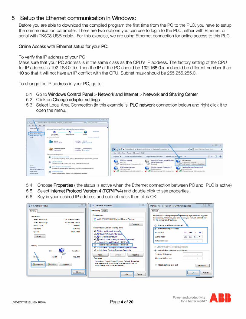
5 Setup the Ethernet communication in Windows: Before you are able to download the compiled program the first time from the PC to the PLC, you have to setup the communication parameter. There are two options you can use to login to the PLC, either with Ethernet or serial with TK503 USB cable. For this exercise, we are using Ethernet connection for online access to this PLC. Online Access with Ethernet setup for your PC:
To verify the IP address of your PC Make sure that your PC address is in the same class as the CPU’s IP address. The factory setting of the CPU for IP address is 192.168.0.10. Then the IP of the PC should be 192.168.0.x, x should be different number than 10 so that it will not have an IP conflict with the CPU. Subnet mask should be 255.255.255.0.
To change the IP address in your PC, go to:
5.1 Go to Windows Control Panel > Network and Internet > Network and Sharing Center 5.2 Click on Change adapter settings 5.3 Select Local Area Connection (in this example is PLC network connection below) and right click it to
open the menu.
5.4 Choose Properties ( the status is active when the Ethernet connection between PC and PLC is active) 5.5 Select Internet Protocol Version 4 (TCP/IPv4) and double click to see properties. 5.6 Key in your desired IP address and subnet mask then click OK.
LVD-EOTN112U-EN REVA Page 5 of 20
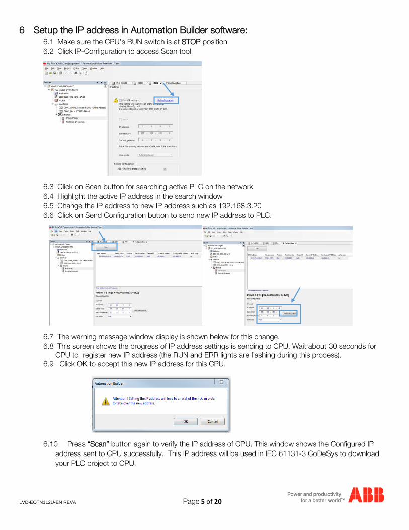
6 Setup the IP address in Automation Builder software: 6.1 Make sure the CPU’s RUN switch is at STOP position 6.2 Click IP-Configuration to access Scan tool
6.3 Click on Scan button for searching active PLC on the network 6.4 Highlight the active IP address in the search window 6.5 Change the IP address to new IP address such as 192.168.3.20 6.6 Click on Send Configuration button to send new IP address to PLC.
6.7 The warning message window display is shown below for this change. 6.8 This screen shows the progress of IP address settings is sending to CPU. Wait about 30 seconds for
CPU to register new IP address (the RUN and ERR lights are flashing during this process). 6.9 Click OK to accept this new IP address for this CPU.
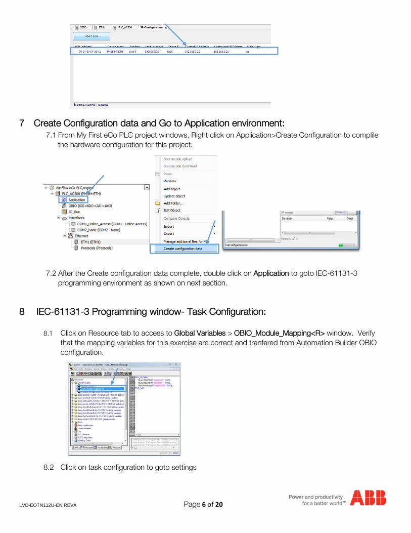
6.10 Press “Scan” button again to verify the IP address of CPU. This window shows the Configured IP address sent to CPU successfully. This IP address will be used in IEC 61131-3 CoDeSys to download your PLC project to CPU.
LVD-EOTN112U-EN REVA Page 6 of 20
7 Create Configuration data and Go to Application environment: 7.1 From My First eCo PLC project windows, Right click on Application>Create Configuration to complile
the hardware configuration for this project.
7.2 After the Create configuration data complete, double click on Application to goto IEC-61131-3
programming environment as shown on next section.
8 IEC-61131-3 Programming window- Task Configuration:
8.1 Click on Resource tab to access to Global Variables > OBIO_Module_Mapping<R> window. Verify that the mapping variables for this exercise are correct and tranfered from Automation Builder OBIO configuration.
8.2 Click on task configuration to goto settings
LVD-EOTN112U-EN REVA Page 7 of 20
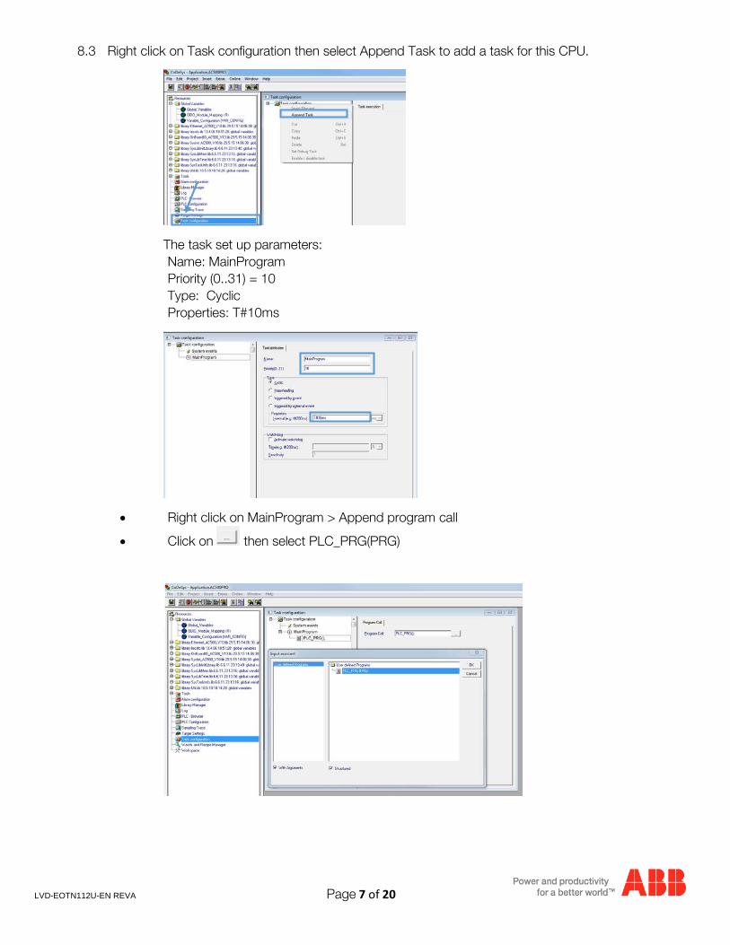
8.3 Right click on Task configuration then select Append Task to add a task for this CPU.
The task set up parameters: Name: MainProgram Priority (0..31) = 10 Type: Cyclic Properties: T#10ms
• Right click on MainProgram > Append program call
• Click on then select PLC_PRG(PRG)
LVD-EOTN112U-EN REVA Page 8 of 20
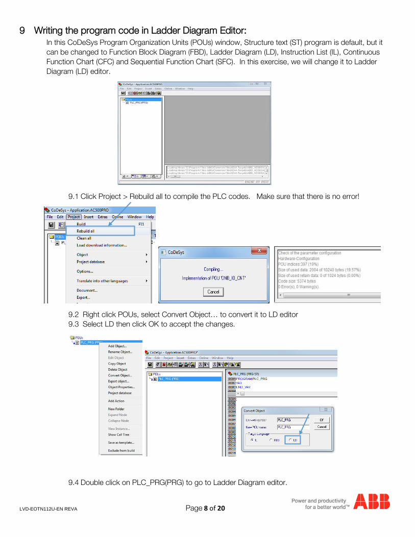
9 Writing the program code in Ladder Diagram Editor: In this CoDeSys Program Organization Units (POUs) window, Structure text (ST) program is default, but it can be changed to Function Block Diagram (FBD), Ladder Diagram (LD), Instruction List (IL), Continuous Function Chart (CFC) and Sequential Function Chart (SFC). In this exercise, we will change it to Ladder Diagram (LD) editor.
9.1 Click Project > Rebuild all to compile the PLC codes. Make sure that there is no error!
9.2 Right click POUs, select Convert Object… to convert it to LD editor 9.3 Select LD then click OK to accept the changes.
9.4 Double click on PLC_PRG(PRG) to go to Ladder Diagram editor.
LVD-EOTN112U-EN REVA Page 9 of 20
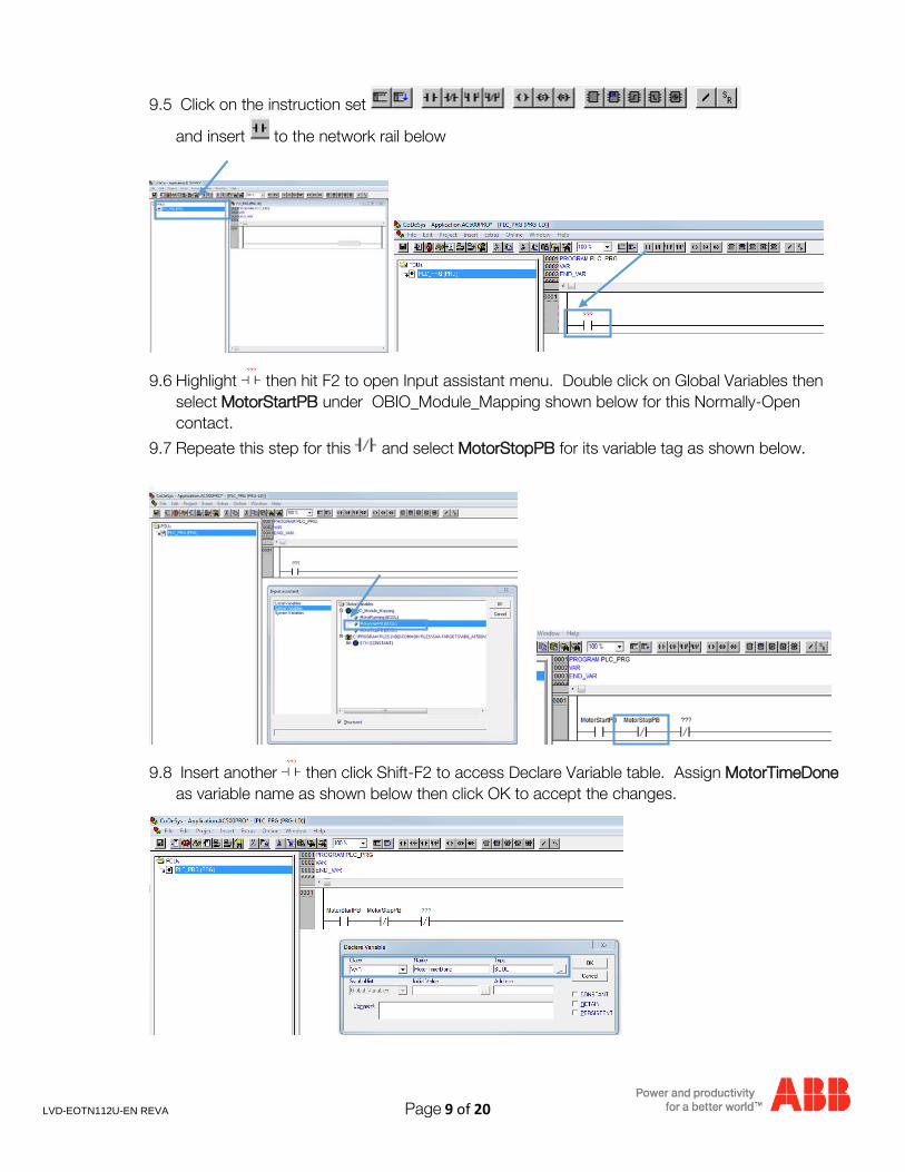
9.5 Click on the instruction set
and insert to the network rail below
9.6 Highlight then hit F2 to open Input assistant menu. Double click on Global Variables then select MotorStartPB under OBIO_Module_Mapping shown below for this Normally-Open contact.
9.7 Repeate this step for this and select MotorStopPB for its variable tag as shown below.
9.8 Insert another then click Shift-F2 to access Declare Variable table. Assign MotorTimeDone as variable name as shown below then click OK to accept the changes.
LVD-EOTN112U-EN REVA Page 10 of 20
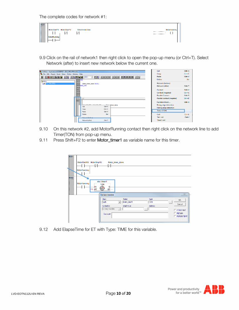
The complete codes for network #1:
9.9 Click on the rail of network1 then right click to open the pop-up menu (or Ctrl+T). Select Network (after) to insert new network below the current one.
9.10 On this network #2, add MotorRunning contact then right click on the network line to add Timer(TON) from pop-up menu.
9.11 Press Shift+F2 to enter Motor_timer1 as variable name for this timer.
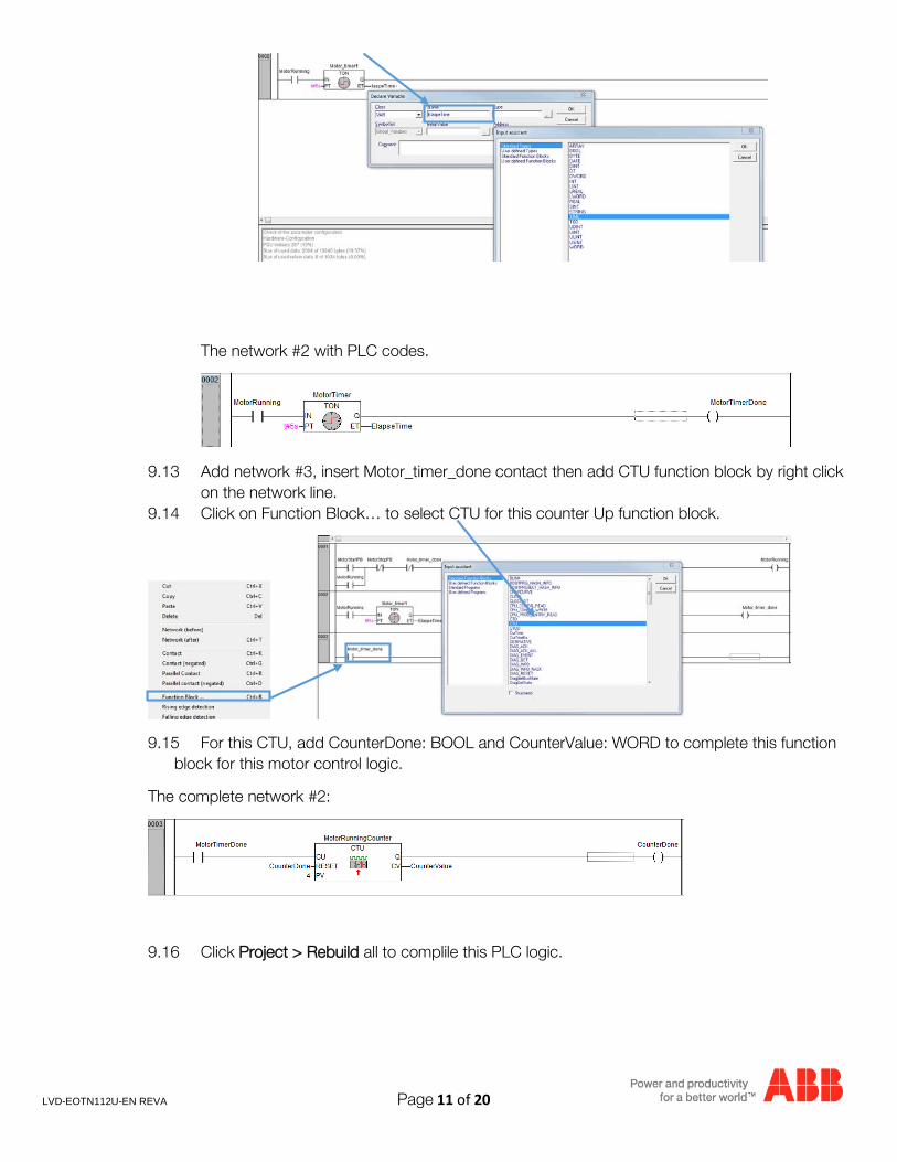
9.12 Add ElapseTime for ET with Type: TIME for this variable.
LVD-EOTN112U-EN REVA Page 11 of 20
The network #2 with PLC codes.
9.13 Add network #3, insert Motor_timer_done contact then add CTU function block by right click on the network line.
9.14 Click on Function Block… to select CTU for this counter Up function block.
9.15 For this CTU, add CounterDone: BOOL and CounterValue: WORD to complete this function block for this motor control logic.
The complete network #2:
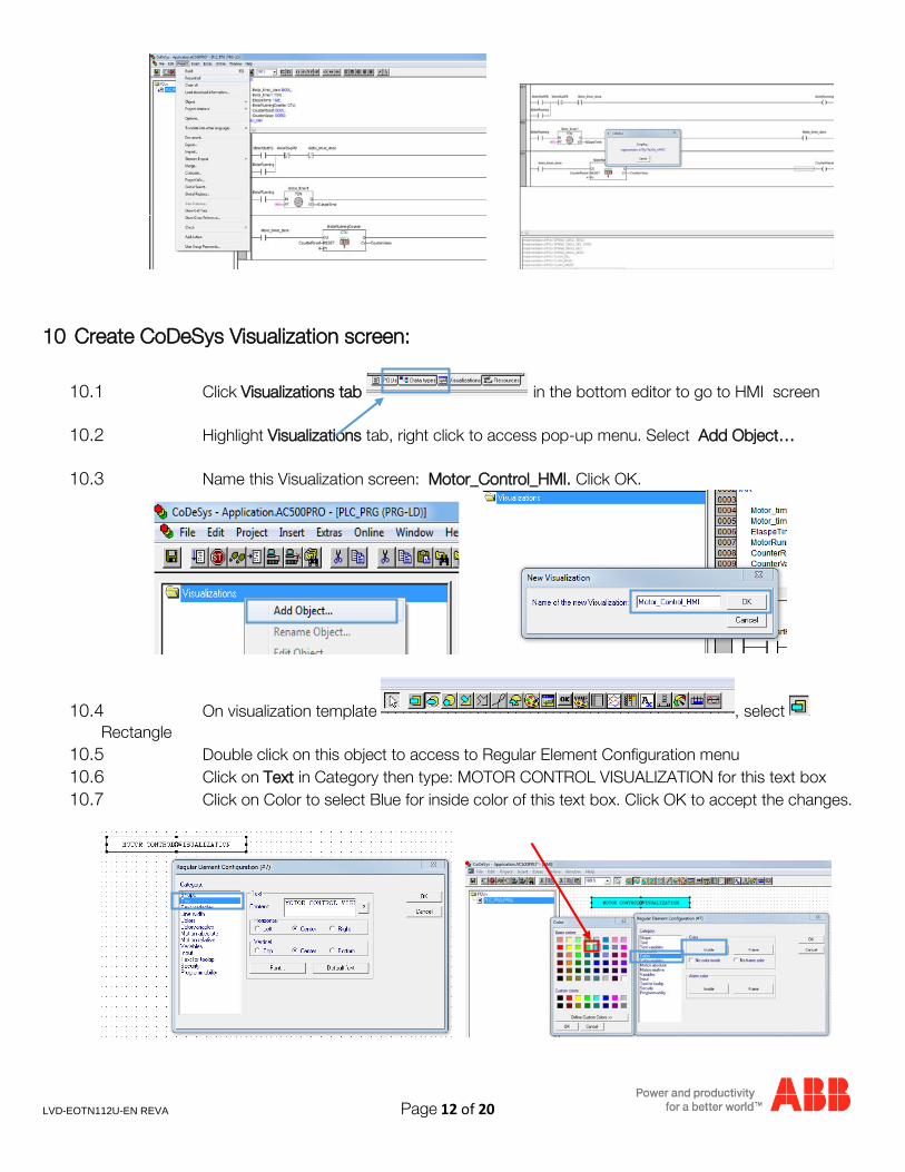
9.16 Click Project > Rebuild all to complile this PLC logic.
LVD-EOTN112U-EN REVA Page 12 of 20
10 Create CoDeSys Visualization screen:
10.1 Click Visualizations tab in the bottom editor to go to HMI screen
10.2 Highlight Visualizations tab, right click to access pop-up menu. Select Add Object…
10.3 Name this Visualization screen: Motor_Control_HMI. Click OK.
10.4 On visualization template , select Rectangle
10.5 Double click on this object to access to Regular Element Configuration menu 10.6 Click on Text in Category then type: MOTOR CONTROL VISUALIZATION for this text box 10.7 Click on Color to select Blue for inside color of this text box. Click OK to accept the changes.
LVD-EOTN112U-EN REVA Page 13 of 20
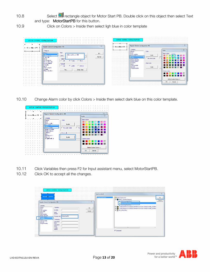
10.8 Select rectangle object for Motor Start PB. Double click on this object then select Text and type: MotorStartPB for this button.
10.9 Click on Colors > Inside then select ligh blue in color template
10.10 Change Alarm color by click Colors > Inside then select dark blue on this color template.
10.11 Click Variables then press F2 for Input assistant menu, select MotorStartPB. 10.12 Click OK to accept all the changes.
LVD-EOTN112U-EN REVA Page 14 of 20
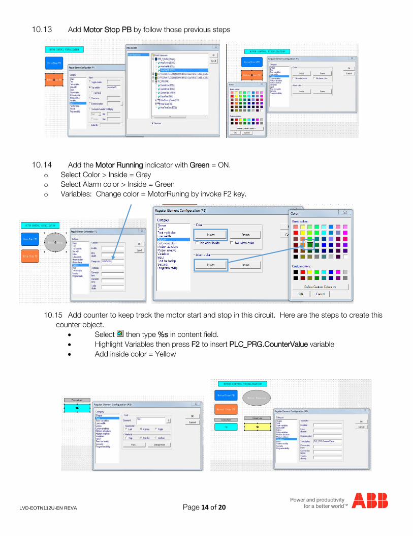
10.13 Add Motor Stop PB by follow those previous steps
10.14 Add the Motor Running indicator with Green = ON. o Select Color > Inside = Grey o Select Alarm color > Inside = Green o Variables: Change color = MotorRuning by invoke F2 key.
10.15 Add counter to keep track the motor start and stop in this circuit. Here are the steps to create this counter object.
• Select then type %s in content field. • Highlight Variables then press F2 to insert PLC_PRG.CounterValue variable • Add inside color = Yellow
LVD-EOTN112U-EN REVA Page 15 of 20
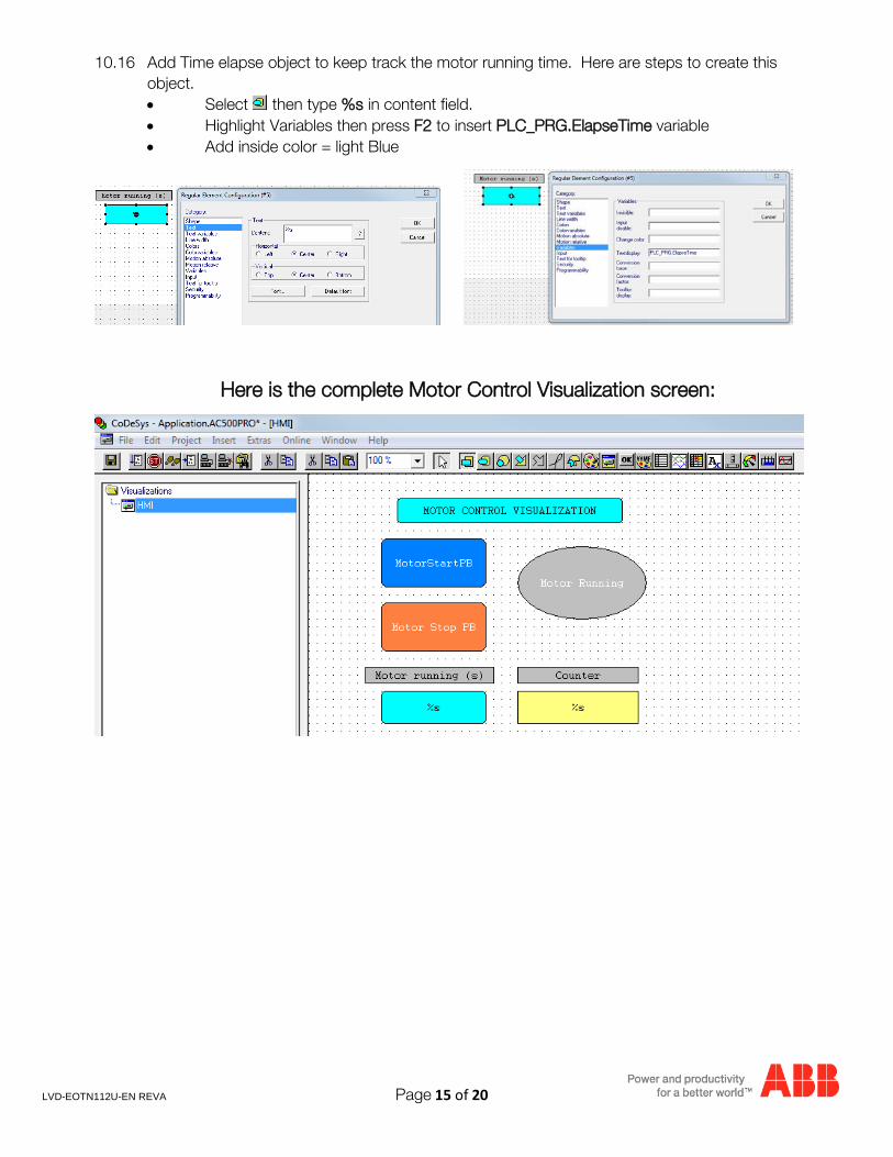
10.16 Add Time elapse object to keep track the motor running time. Here are steps to create this object. • Select then type %s in content field. • Highlight Variables then press F2 to insert PLC_PRG.ElapseTime variable • Add inside color = light Blue
Here is the complete Motor Control Visualization screen:
LVD-EOTN112U-EN REVA Page 16 of 20
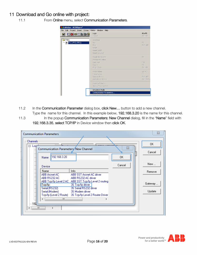
11 Download and Go online with project: 11.1 From Online menu, select Communication Parameters.
11.2 In the Communication Parameter dialog box, click New… button to add a new channel. Type the name for this channel. In this example below, 192.168.3.20 is the name for this channel.
11.3 In the popup Communication Parameters: New Channel dialog, fill in the “Name” field with 192.168.3.35, select TCP/IP in Device window then click OK.
LVD-EOTN112U-EN REVA Page 17 of 20
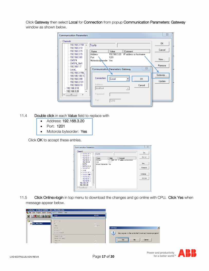
Click Gateway then select Local for Connection from popup Communication Parameters: Gateway window as shown below.
11.4 Double click in each Value field to replace with • Address: 192.168.3.20 • Port: 1201 • Motorola byteorder: Yes
Click OK to accept these entries.
11.5 Click Online>login in top menu to download the changes and go online with CPU. Click Yes when message appear below.
LVD-EOTN112U-EN REVA Page 18 of 20
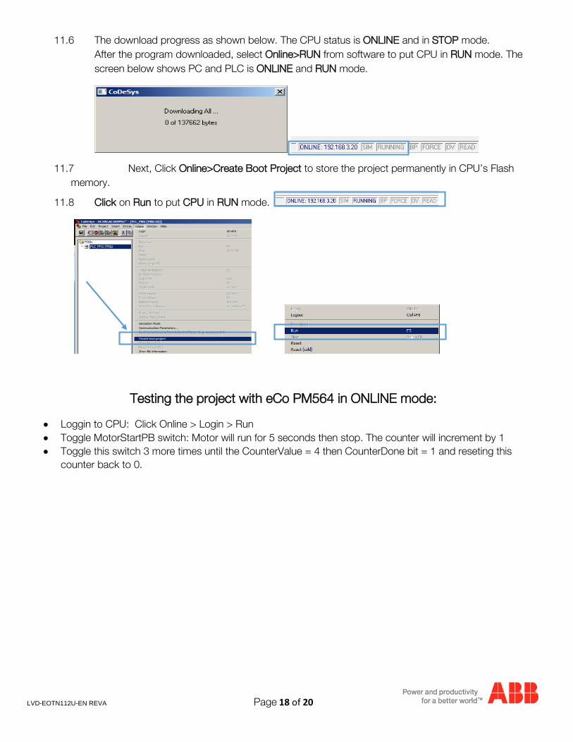
11.6 The download progress as shown below. The CPU status is ONLINE and in STOP mode. After the program downloaded, select Online>RUN from software to put CPU in RUN mode. The screen below shows PC and PLC is ONLINE and RUN mode.
11.7 Next, Click Online>Create Boot Project to store the project permanently in CPU’s Flash memory.
11.8 Click on Run to put CPU in RUN mode.
Testing the project with eCo PM564 in ONLINE mode:
• Loggin to CPU: Click Online > Login > Run • Toggle MotorStartPB switch: Motor will run for 5 seconds then stop. The counter will increment by 1 • Toggle this switch 3 more times until the CounterValue = 4 then CounterDone bit = 1 and reseting this
counter back to 0.
LVD-EOTN112U-EN REVA Page 19 of 20
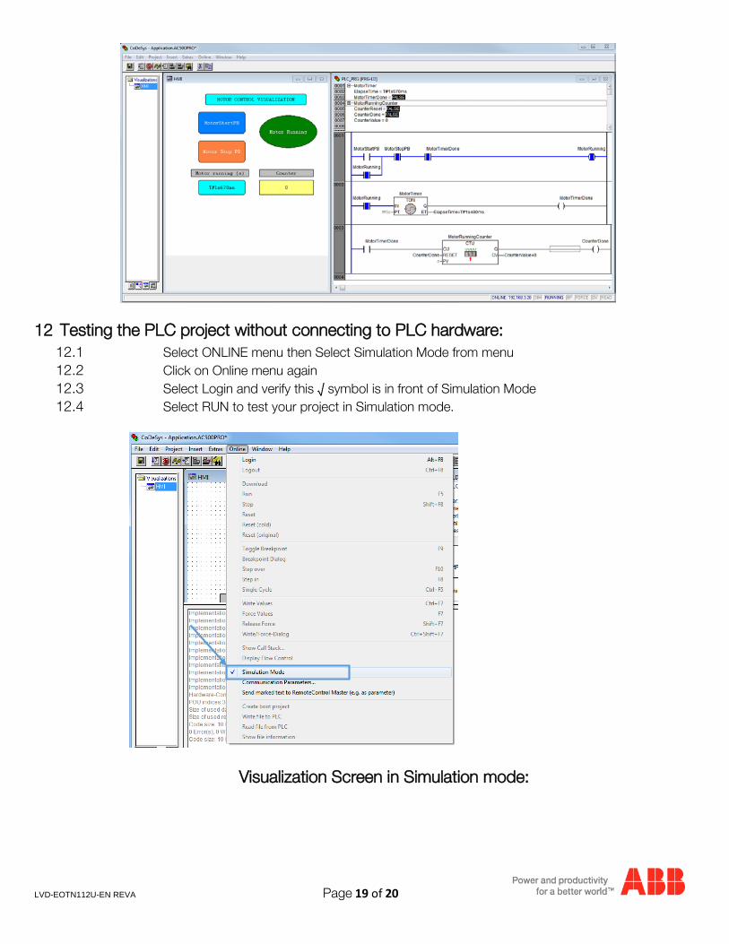
12 Testing the PLC project without connecting to PLC hardware: 12.1 Select ONLINE menu then Select Simulation Mode from menu 12.2 Click on Online menu again 12.3 Select Login and verify this √ symbol is in front of Simulation Mode 12.4 Select RUN to test your project in Simulation mode.
Visualization Screen in Simulation mode:
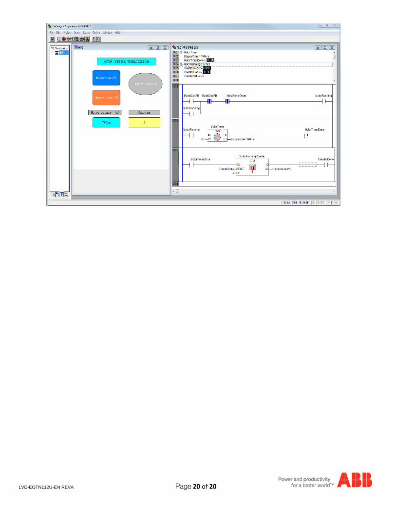
LVD-EOTN112U-EN REVA Page 20 of 20