AC500 PLCs 4 - · PDF file4 AC500 PLCs 4 Low Voltage Products & Systems 4.5 Control Builder...
23
4 Low Voltage Products & Systems 4.1 AC500 PLCs Index AC500 grows to meet requirements..................................................................................... 4.3 AC500 ordering data ................................................................................................ 4.16 - 4.19 Approvals ........................................................................................................................... 4.21 Arcnet ................................................................................................................................. 4.10 CANopen .............................................................................................................................. 4.9 Communication .......................................................................................................... 4.6 - 4.11 CS31................................................................................................................................... 4.11 DeviceNet ............................................................................................................................. 4.9 Dimensions ......................................................................................................................... 4.20 Ethernet ................................................................................................................................ 4.6 General information .............................................................................................................. 4.2 Modbus ................................................................................................................................ 4.8 Networked ............................................................................................................................ 4.4 Profibus DP .......................................................................................................................... 4.7 Programming ........................................................................................................................ 4.5 Technical data .......................................................................................................... 4.12 - 4.15 Gross Automation (877) 268-3700 · www.abbplc.com · [email protected]
-
Upload
trinhquynh -
Category
Documents
-
view
243 -
download
5
Transcript of AC500 PLCs 4 - · PDF file4 AC500 PLCs 4 Low Voltage Products & Systems 4.5 Control Builder...

4
4AC500 PLCs
Low Voltage Products & Systems 4.1
AC500 PLCs
Index
AC500 grows to meet requirements ..................................................................................... 4.3
AC500 ordering data ................................................................................................ 4.16 - 4.19
Approvals ........................................................................................................................... 4.21
Arcnet ................................................................................................................................. 4.10
CANopen .............................................................................................................................. 4.9
Communication .......................................................................................................... 4.6 - 4.11
CS31 ................................................................................................................................... 4.11
DeviceNet ............................................................................................................................. 4.9
Dimensions ......................................................................................................................... 4.20
Ethernet ................................................................................................................................ 4.6
General information .............................................................................................................. 4.2
Modbus ................................................................................................................................ 4.8
Networked ............................................................................................................................ 4.4
Profi bus DP .......................................................................................................................... 4.7
Programming ........................................................................................................................ 4.5
Technical data .......................................................................................................... 4.12 - 4.15
Gross Automation (877) 268-3700 · www.abbplc.com · [email protected]

4
4
4.2 Low Voltage Products & Systems
AC500 PLCs
Clear advantages thanks to clear structures
Flexibility as program Thanks to its scalability, the AC500 PLC can be adapted to the most different automation tasks: The devices concerned can be used and combined in a flexible way. The number of different parts to be kept in stock is correspondingly mini-mized.
The AC500’s system architecture
CPUs CPUs are available in the performance classes PM571, PM581 and PM591, can all be programmed in five different languages, and provide an LCD display, an operator keypad, an SD card slot, andtwo integrated serial interfaces. The CPUs can be simply plugged onto the CPU terminal base. Optionally,they are also available with integrated Ethernet or ARCNET. The CPU terminal base Available in three different versions, enables easy plugging of the CPU and one, two or four communication modules.
The I/O modules Digital and analog in different versions. Can be simply plugged onto the terminal units – for local expansion of the CPU (max. seven modules) and decentralized expansion via the FBP interface. Flexible use thanks to configu-rable channels.
The terminal units Multi-purpose usage for both digital and analog I/Os, for 1, 2 and 3-wire designs. Enable simple prewiring without electronics. For 24 V DC and 230 V AC, optionally for spring or screw-type terminals.
The communication modules For connection to standard field bus systems and integration into existing networks. Up to four communication modules in any desired combination are allowed at one CPU, resulting in a high degree of communication.
The FBP interface module With embedded digital I/Os and a field-bus-neutral interface for connecting the chosen FBP connector. For decentralized expansion by up to seven I/O modules.
The SD card Optional for data logging, downloading and uploading the user program without a PC or a firmware update for all devices (CPU, couplers or I/O modules).
2
1
31
5
4
67
1 Back-lighted LCD display and keypad
2 SD card slot
3 Plug-in communication modules (1 to max. 4)
4 Optionally with integrated Ethernet or ARCNET
5 FBP interface (for slave)
6 Two serial interfaces for programming, ASCII, Modbus or CS31 field bus (master)
7 Expandable by up to seven local I/O modules
General information
Gross Automation (877) 268-3700 · www.abbplc.com · [email protected]

4
4AC500 PLCs
Low Voltage Products & Systems 4.3
AC500 grows to meet requirements
Control + communication:
Decentralized expansion:
Centralized expansion:
Gross Automation (877) 268-3700 · www.abbplc.com · [email protected]
4
4
4.4 Low Voltage Products & Systems
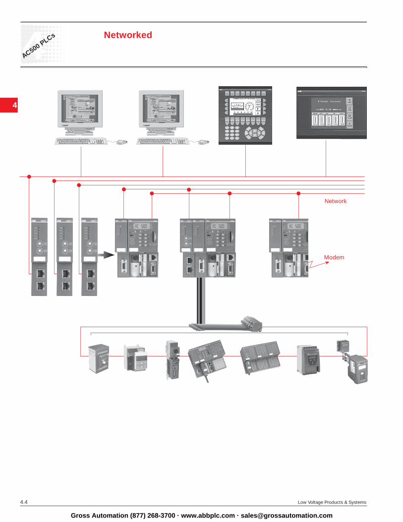
AC500 PLCs Networked
Network
Modem
Gross Automation (877) 268-3700 · www.abbplc.com · [email protected]

4
4AC500 PLCs
Low Voltage Products & Systems 4.5
Control Builder AC500
Control Builder AC500 is the engineering tool for all CPU performance classes of the AC500, designed for standardized IEC 61131-3 programming in five different languages. Other features of this tool are: Configuration of the over-all system including field buses and interfaces, extensive diagnostic func-tions, alarm handling, integrated visualization and open software interfaces.
Programming in conformity with IEC 61131-3 Besides the suitable hardware, a high-performance, user-friendly and convenient engineering tool is indispensable for simple planning, pro-gramming, testing and commissioning of an automation applica-tion. AC500 Control Builder provides the following functionalities: • Five standardized programming languages: Function Block Diagram (FBD), Instruction List (IL), Ladder Diagram (LD), Structured Text (ST), Sequen tial Function Chart (SFC) • Free graphical function chart (CFC) • Debugging functions for the program test: - Single step - Single cycle - Breakpoint
Offline simulation IEC 61131-3 commands can be simulated without a PLC being con-nected, including the relevant malfunctions. After the program test, the application can be downloaded to the control system.
Sampling trace Timing diagrams for process variables and stor-age of data in a ring buffer with event trigger.
Recipe management and watch lists Values of selected variables are displayed. Pre-defined values can be assigned to variables which can then be downloaded to the control sys-tem all at once (“Write recipe”). Ongoing values from the control system can also be pre-assigned for reading into the Watch and Recipe Man-ager, and stored in memory there (“Read recipe). These functions are also helpful, for example, for setting and entering control parameters.
Visualization Includes color change, moving elements, bitmaps, text display, allows input of setpoint values and display of process variables read from the PLC, dynamic bar diagrams, alarm and event management, function keys and ActiveX elements.
Configurators of the communication interfaces For PROFIBUS DP, CANopen, DeviceNet, Ethernet, Modbus and CS31.
Open interfaces DDE and OPC.
Programming Serial or via Ethernet or ARCNET networks.
Engineering interface Provides access from the programming system to an external project database in which the program source code of one or several automa-tion projects is managed. Optionally, a version control system, such as Visual Source Safe, can be used in order to ensure data consis-tency of the program code for several different users and projects. • Comprehensive libraries. • Windows 32-bit standard. • Operating systems Windows NT, 2000 and XP.
Member of Automation Alliance
Programming
Gross Automation (877) 268-3700 · www.abbplc.com · [email protected]

4
4
4.6 Low Voltage Products & Systems
AC500 PLCs
Ethernet
Ethernet operates with a data rate of 10 MBit/s and as Fast-Ethernet with 100 MBit/s. Ethernet utilizes the producer/consumer model. This means that every station possesses equal rights. While it is transmitting, all other stations listen in and accept the data directed to them. Bus access is regulated by the CSMA/CD procedure (Carrier-Sense Multiple-Access with Collision Detection), where each station may autonomously transmit when the bus is free. If a collision occurs, if two stations begin to transmit simultaneously, both of them will stop transmis-sion and wait for a randomly determined time before they transmit again. Eth-ernet defines the Layers 1 (Physical Link) and 2 (Data Link) of the OSI model.
The AC500 supports transmission and reception of data using TCP/IP and/or UDP/IP. Further application layers can be implemented by subsequent loading. Simultaneous operation of TCP/IP, UDP/IP and application layer is also assured. The IP, TCP, UDP, ARP, RP, BOOTP, and DHCP protocols are supported as a standard feature, as application layer Modbus/TCP.
TopologyStar- or ring-shaped using Ethernet hub or switch.
Data transmission Max. 10 MB/s with 10 Base T and max. 100 MB/s with Fast-Ethernet.
Transmission media Twisted-pair cables with RJ45 connector. The maximum cable length is 100 m for 100 MB/s.
DiagnosticsDetailed diagnostic messages for rapid trouble-shoot-ing are shown on the CPU display.In addition, the device status is indicated at the com-munication module by four LEDs.
CommunicationEthernet
Gross Automation (877) 268-3700 · www.abbplc.com · [email protected]

4
4AC500 PLCs
Low Voltage Products & Systems 4.7
Process Field Bus - Decentral Periphery
PROFIBUS DP is an open, high-speed and widely-used field bus. It provides multi-master and master-slave communication in the field area. This field bus can accordingly be used for AC500 and AC31 control system series and for field-bus-neutral FBP devices (decentralized I/Os and intelligent switching devices) via the PROFIBUS-FBP connector.
Communication The masters rule data traffic on the bus. When in possession of the bus access authorization (token), the masters can transmit data without an external request. The passive devices, known as slaves, do not receive any bus access rights; they acknowledge messages received, or respond to a query from a master. Baud rates from 9.6 kBaud to 12 MBaud are supported. A maximum of 126 devices can be operated on the bus.
Data exchange This is handled predominantly in cyclical mode be-tween master and slave. The requisite communication functions have been specified by the PROFIBUS DP basic functions in accordance with EN 50170. Each master has full write and read access to its assigned slaves, but only read access to the slaves assigned to other bus masters. There is no direct data exchange between masters. Acyclical services (DP-V1) for parameterization and diagnostics between master and slave are also available. This is performed in parallel to the master’s cyclical user data traffic.
PROFIBUS DP – the functionality at a glance • Max. 126 subscribers via amplifier and max. 32 subscribers (master/slaves) per
bus segment • Data transmission rate from max. 12 MBit/s with a cable length of 100 m, up to
93.75 kBit/s with 1200 m • Multi-master or master/slave communication. Bus access of the masters using
token • Connection of the master CPU and the associated communication module via
a 9-pole SUB-D plug connector. Connection of slaves (CPU, I/Os and intelligent switching devices) via FieldBusPlug
• The system cable is a shielded twisted-pair line or a fiber-optic cable; transmis-sion standard EIA RS485
Diagnostics Detailed diagnostic messages for rapid trouble-shooting are shown on the CPU display. In addition, the device status is indicated at the communica-tion module by four LEDs.
CommunicationPROFIBUS DP
Gross Automation (877) 268-3700 · www.abbplc.com · [email protected]
4
4
4.8 Low Voltage Products & Systems
AC500 PLCs
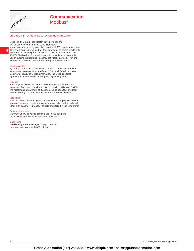
Modbus® RTU (developed by Modicon in 1979)
Modbus® RTU is an open master/slave protocol, and can be easily implemented on serial interfaces. Numerous automation systems have Modbus® RTU interfaces as stan-dard or optional features, and are thus easily able to communicate with the AC500 via its integrated COM1 and COM2 interfaces (RS232 or RS485). The Modbus® is used not only in industrial applications, but also in building installations, in energy optimization systems, for long-distance data transmission and for linking up operator panels.
Communication By polling, i.e. the master transmits a request to the slave and then receives the response. Both interfaces COM1 and COM2 can oper-ate simultaneously as Modbus interfaces. The Modbus operat-ing mode of an interface is set using the engineering tool.
Topology Point-to-point via RS232 or multi-point via RS485. With RS232, a maximum of one master and one slave is possible, while with RS485 one master and a maximum of 31 slaves can be operated. The maxi-mum cable length is 15 m with RS232 and 1.2 km with RS485.
Data transfer Max. 187.5 kB/s. Each telegram has a 16-bit CRC appended. The tele-grams permit process data (input/output data) to be written and read, either individually or in groups. The data are packed in the RTU format.
Transmission media May vary. One widely used option is the RS485 bus phys-ics, a twisted-pair, shielded cable with terminators.
DiagnosticsDetailed diagnostic messages for rapid trouble-shoot-ing are shown on the CPU display.
CommunicationModbus®
Gross Automation (877) 268-3700 · www.abbplc.com · [email protected]

4
4AC500 PLCs
Low Voltage Products & Systems 4.9
CANopen (Controller Area Network) and DeviceNet
The CAN protocol was originally developed for the European automotive industry, so as to replace expensive cabling by an affordable network cable. Today, it is also used in the field of automation for transmitting process data between control systems, decentralized
I/O modules, drives, valves, etc. CAN features a high level of transmission security, since large portions of the monitoring mechanisms have been imple-mented directly in the CAN chip. DeviceNet and CANopen utilize the physical structure and the data transport mechanisms of CAN (Controller Area Network). The difference lies in the transmission protocols. DeviceNet and CANopen can be used correspondingly for the AC500 and AC31 controller series and for field-bus-neutral FBP devices (decentralized I/Os and intelligent switching devices), via the CANopen-FBP plug connector.
Data transmission Two types of message have been defined: I/O data transfer and direct link. I/O data transfer is used for time-critical process data, while the direct link can be, for example, used for diagnostic messages.
Bus access for subscribers The connection ID with the lower address has higher priority on the bus. Data is transmitted by the source, while the sinks (i.e. receivers of the data) have like wise been specified during the configuration phase.
CANopenThe bus operates on the master/slave principle with one master and up to 127 slaves. A shielded twisted-pair cable is used, according to ISO 11898. Cable lengths and transmission rates: from max. 40 m at 1 MBit/s to 1000 m at 20 kBit/s.
DeviceNetThe bus operates on the multi-master and/or the master/slave principle, with up to 64 bus subscribers. Two types of shielded twisted-pair cables are used: trunk cable for the main line and drop cable for the branch line.
Transmission rate 125 kBit/s 250 kBit/s 500 kBit/s
Max. cable length of trunk line 500 m 250 m 100 mTrunk cable (1610 ft) (820 ft) (328 ft)
Max. cable length of trunk line 100 m 100 m 100 mDrop cable (328 ft) (328 ft) (328 ft)
Max. cable length per branch line 6 m 6 m 6 mTrunk cable/Drop cable (20 ft) (20 ft) (20 ft)
Max. cable length total branch line 156 m 78 m 39 mTrunk cable/Drop cable (512 ft) (256 ft) (128 ft)
Diagnostics Detailed diagnostic messages for rapid trouble-shooting are shown on the CPU display. In addition, the device status is indicated at the communication module by four LEDs.
CommunicationCANopen and DeviceNet
Gross Automation (877) 268-3700 · www.abbplc.com · [email protected]
4
4
4.10 Low Voltage Products & Systems
AC500 PLCs
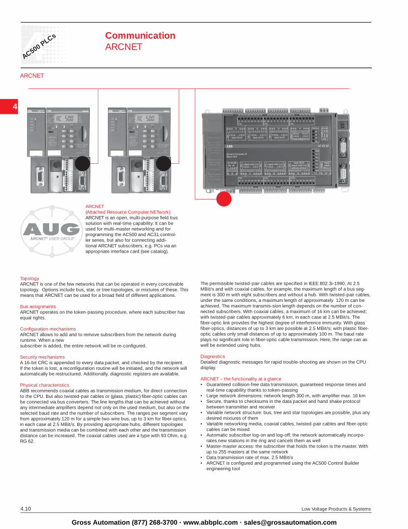
ARCNET
Topology ARCNET is one of the few networks that can be operated in every conceivable topology. Options include bus, star, or tree topologies, or mixtures of these. This means that ARCNET can be used for a broad field of different applications.
Bus assignments ARCNET operates on the token-passing procedure, where each subscriber has equal rights.
Configuration mechanisms ARCNET allows to add and to remove subscribers from the network during runtime. When a newsubscriber is added, the entire network will be re-configured.
Security mechanisms A 16-bit CRC is appended to every data packet, and checked by the recipient. If the token is lost, a reconfiguration routine will be initiated, and the network will automatically be restructured. Additionally, diagnostic registers are available.
Physical characteristics ABB recommends coaxial cables as transmission medium, for direct connection to the CPU. But also twisted-pair cables or (glass, plastic) fiber-optic cables can be connected via bus converters. The line lengths that can be achieved without any intermediate amplifiers depend not only on the used medium, but also on the selected baud rate and the number of subscribers. The ranges per segment vary from approximate ly 120 m for a simple two-wire bus, up to 3 km for fiber-optics, in each case at 2.5 MBit/s. By providing appropriate hubs, different topologies and transmis sion media can be combined with each other and the transmission distance can be increased. The coaxial cables used are a type with 93 Ohm, e.g. RG 62.
CommunicationARCNET
ARCNET (Attached Resource Computer NETwork)ARCNET is an open, multi-purpose field bus solution with real-time capability. It can be used for multi-master networking and for programming the AC500 and AC31 control-ler series, but also for connecting addi-tional ARCNET subscribers, e.g. PCs via an appropriate interface card (see catalog).
The permissible twisted-pair cables are specified in IEEE 802.3i-1990. At 2.5 MBit/s and with coaxial cables, for example, the maximum length of a bus seg-ment is 300 m with eight subscribers and without a hub. With twisted-pair cables, under the same conditions, a maximum length of approximately 120 m can be achieved. The maximum transmis -sion length depends on the number of con-nected subscribers. With coaxial cables, a maximum of 16 km can be achieved; with twisted-pair cables approximately 6 km, in each case at 2.5 MBit/s. The fiber-optic link provides the highest degree of interference immunity. With glass fiber-optics, distances of up to 3 km are possible at 2.5 MBit/s; with plastic fiber-optic cables only small distances of up to approximately 100 m. The baud rate plays no significant role in fiber-optic cable transmission. Here, the range can as well be extended using hubs.
DiagnosticsDetailed diagnostic messages for rapid trouble-shooting are shown on the CPU display.
ARCNET – the functionality at a glance • Guaranteed collision-free data transmission, guaranteed response times and
real-time capability thanks to token-passing • Large network dimensions: network length 300 m, with amplifier max. 16 km• Secure, thanks to checksums in the data packet and hand shake protocol between transmitter and receiver• Variable network structure: bus, tree and star topologies are possible, plus any desired mixtures of them • Variable networking media, coaxial cables, twisted-pair cables and fiber-optic cables can be mixed • Automatic subscriber log-on and log-off; the network automatically incorpo-
rates new stations in the ring and cancels them as well• Master-master access: the subscriber that holds the token is the master. With
up to 255 masters at the same network • Data transmission rate of max. 2.5 MBit/s • ARCNET is configured and programmed using the AC500 Control Builder engineering tool
Gross Automation (877) 268-3700 · www.abbplc.com · [email protected]
4
4AC500 PLCs
Low Voltage Products & Systems 4.11
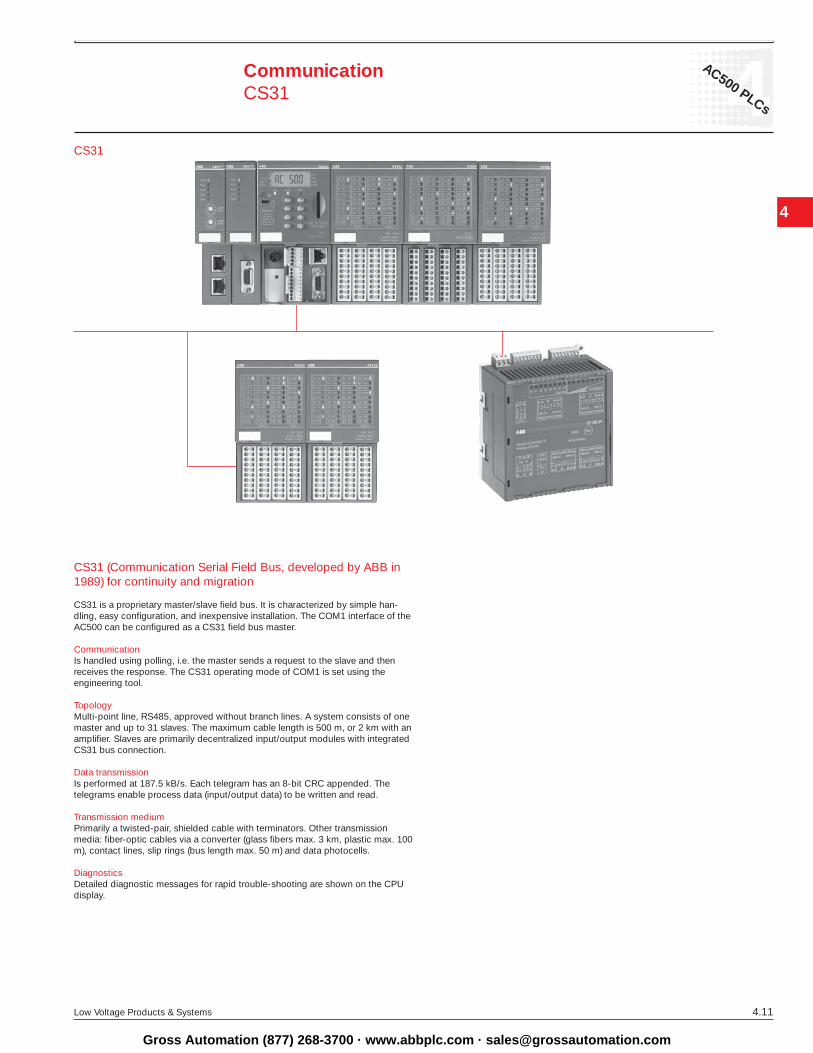
CS31 (Communication Serial Field Bus, developed by ABB in 1989) for continuity and migration
CS31 is a proprietary master/slave field bus. It is characterized by simple han-dling, easy configuration, and inexpensive installation. The COM1 interface of the AC500 can be configured as a CS31 field bus master.
Communication Is handled using polling, i.e. the master sends a request to the slave and then receives the response. The CS31 operating mode of COM1 is set using the engineering tool.
Topology Multi-point line, RS485, approved without branch lines. A system consists of one master and up to 31 slaves. The maximum cable length is 500 m, or 2 km with an amplifier. Slaves are primarily decentralized input/output modules with integrated CS31 bus connection.
Data transmission Is performed at 187.5 kB/s. Each telegram has an 8-bit CRC appended. The telegrams enable process data (input/output data) to be written and read.
Transmission medium Primarily a twisted-pair, shielded cable with terminators. Other transmission media: fiber-optic cables via a converter (glass fibers max. 3 km, plastic max. 100 m), contact lines, slip rings (bus length max. 50 m) and data photocells.
Diagnostics Detailed diagnostic messages for rapid trouble-shooting are shown on the CPU display.
CommunicationCS31
CS31
Gross Automation (877) 268-3700 · www.abbplc.com · [email protected]

4
4
4.12 Low Voltage Products & Systems
AC500 PLCs Technical data
DetailsType: PM571 PM571-ETH PM581 PM581-ETH PM581-ARC PM591 PM591-ETH PM591-ARC
Supply voltage 24 V DC 24 V DC 24 V DC 24 V DC
Total memorySDRAM (kByte) 4026 8192 32768Flash (kByte) 1024 2048 8192SRAM (kByte) 128 512 2048
Program memory Flash EPROM und RAM [kByte] 64 256 4096
Data memory integrated [kByte] 21, incl. 1 KB RETAIN 288, incl. 32 KB RETAIN 3072, incl. 512 KB RETAIN
Plug-in memory card [SD card] 128 MB 128 MB 128 MB
Cycle time for 1000 instructions in msBinary 0.3 0.15 0.05Word 0.3 0.15 0.05Floating-point 6 3 0.5
Number of centralized inputs/outputs max. Binary inputs 224 224 224Binary outputs 168 168 168Analog inputs 112 112 112Analog outputs 112 112 112
Number of decentralized inputs/outputs max. depends on used field bus
Data buffering Battery Battery Battery
Real-time clock x x x
Program execution Cyclical x x x Time-controlled x x x Multitasking x x x
User program protection by password x x x
Interfaces integrated
COM1:RS232/RS485 configurable x x xConnection Terminal block Terminal block Terminal block Prog., Modbus, ASCII, CS31 x x x
COM2:RS232/RS485 configurable x x xConnection SUB-D SUB-D SUB-DProg., Modbus, ASCII x x x
Ethernet coupler integrated x x xConnection Ethernet RJ45 RJ45 RJ45
ARCNET coupler integrated x xConnection ARCNET Coax Coax
Display and 8 function keys x x x RUN/STOP RUN/STOP RUN/STOPFunction Status, diagnostics Status, diagnostics Status, diagnostics
Timers unlimited unlimited unlimited
Counters unlimited unlimited unlimited
Function Block Diagram (FBD) x x xInstruction List (IL) x x xLadder Diagram (LD) x x xStructured Text (ST) x x xSequential Function Chart (SFC) x x xContinuous Function Chart (CFC) x x x
Approvals CE, GL, DNV, BV, RINA, LRS, CSA, UL
Gross Automation (877) 268-3700 · www.abbplc.com · [email protected]

4
4AC500 PLCs
Low Voltage Products & Systems 4.13
Technical data
Analog I/O modules AX522
Supply voltage 24 V DC
Number of analog inputs 8
Input ranges 0 ... 10 V, ±10 V0/4 ... 20 mAPt100 -50 ... +400 °C 2/3-wire Pt1000 -50 ... +400 °C 2/3-wire Ni1000 -50 ... +150 °C 2/3-wire
Number of analog outputs 8
Output ranges ±10 V0/4 ... 20 mA(max. 4 current outputs)
Short-circuit/overload protection x
Resolution 12 bit + sign
Potential isolation per module
Operating state indicators Status indication for each input/output LED yellowSupply voltage LED greenFault indicator LED red
Binary I/O modules DI524 DC532 DX522 DX531
Supply voltage 24 V DC 24 V DC 24 V DC 24 V DC
Number of binary inputs and outputs DI/DO/DC (configurable channels) 32/- /- 16 /-/16 8/ 8/- 8/4/-
Input voltage 24 V DC 24 V DC 24 V DC 115 ... 230 V AC
Input time-delay ms configurable configurable configurable typ. 20 0.1/1/8/32 0.1/1/8/32 0.1/1/8/32
Inputs as fast counters* 2 2 2
Counting frequency kHz max. 50 50 50Outputs Transistor 24 V DC, 0,5 A xRelay 230 V AC, 3 A x1) x1)
Total current per module 8 A
Short-circuit/overload protection yes
Potential isolation per module per module per module per module
Operating state indicators Status indication for each input/output LED yellow LED yellow LED yellow LED yellow Supply voltage LED green LED green LED green LED green Fault indicator LED red LED red LED red LED red
Notes 1) changeover contacts *when local I/O modules
Gross Automation (877) 268-3700 · www.abbplc.com · [email protected]

4
4
4.14 Low Voltage Products & Systems
AC500 PLCs
Interface modules DC505-FBP DC551-CS31
Field buses PROFIBUS DP*) CS31CANopen*)
DeviceNet*)
Modbus RTU*)
Interface via FBP integrated
Supply voltage 24 V DC 24 V DC
Number of binary inputs and outputs DI/DO/DC (configurable channels) 8/-/8 8/- /16
Input voltage 24 V DC 24 V DC
Input time-relay configurable configurable0.1/ 1/8/ 32 ms 0.1/ 1/8/ 32 ms
Outputs transistor
Output voltage/current 24 V DC/ 0,5 A 24 V DC/0,5 A
Total current per module 4 A 8 A
Short-circuit/overload protection yes yes
Operating state indicators Supply voltage FBP LED green LED greenFBP communication LED greenCS31 communication LED greenSumcheck error LED red LED redI/O bus communication LED green LED greenStatus indication for each input/output LED yellow LED yellowSupply voltage I/Os LED green LED greenFault indicator I/Os LED red LED red
Potential isolation from the bus from the bus
per module per module
Operating and environmental conditions *) depending on the FBP; the module itself is field-bus-neutral
Voltages according to EN 61131-2
24 V DC Process and supply voltage 24 V DC (-15%, +20% without residual ripple)Absolute limits 19,2 V ... 30 V incl. residual ripple Residual ripple < 5%Polarity reversal protection 10 s
120 V AC Supply voltage 120 V AC (-15%, +10%)Frequency 47 Hz ... 62,4 Hz/50 ... 60 Hz (-6%, +4%)
230 V AC Supply voltage 230 V AC (-15 %, +10%)Frequency 47 Hz ... 62,4 Hz/50 ... 60 Hz (-6%, +4 %)
120–240 V AC Wide voltage input Voltage 102 V ... 264 V/120 V ... 240 V (-15%, +10%)Frequency 47 Hz ... 62,4 Hz/50 ... 60 Hz (-6%, +4%)
Technical data
Gross Automation (877) 268-3700 · www.abbplc.com · [email protected]

4
4AC500 PLCs
Low Voltage Products & Systems 4.15
System dataPower failure bridging time according to EN 61131-2
DC-supply Failure < 10 ms, time between 2 failures > 1 sAC-supply Failure < 0,5 periods, time between 2 failures > 1 s
Temperature Operation 0 °C ... +55 °CStorage -25 °C ... +75 °CTransport -25 °C ... +75 °C
Humidity 50 ... 95%, without condensation
Air pressureOperation > 800 hPa /< 2000 mStorage > 660 hPa / < 3500 m
Creepage distances and clearances
The creepage and clearance distances correspond to Overvoltage Category II, Pollution Severity 2
Electromagnetic compatibility Interference immunity against electrostatic discharge (ESD) acc. to EN 61000-4-2, Zone B, Criteria B Interference voltage with air discharge 8 kVInterference voltage with contact discharge 6 kV
Interference immunityagainst radiated interference (CW radiated) acc. to EN 61000-4-3, Zone B, Criteria A Test field strength 10 V/m
Interference immunityagainst transient interference voltages (burst) acc. to EN 61000-4-4, Zone B, Criteria B
Interference immunity against conduction-bound interferences (CW conducted) acc. to EN 61000-4-6, Zone B, Criteria A Test voltage 3V Zone B
Impulse voltage acc. to EN 61000-4-5, Zone B, Criteria B
Emitted interference acc. to EN 55011, Group 1, Class A
Mechanical data Connection type/Terminals Mounting horizontal Degree of protection IP 20Housing acc. to UL 94 Vibration-resistance all three axes
2 Hz ... 15 Hz, continuous 3,5 mm15 Hz ... 150 Hz, continuous 4 g
Vibration-resistance with SD card plugged in 15 Hz ... 150 Hz, continuous 1 gShock-resistance all three axes
15 g, 11 ms, semi-sinusoidal Device mounting DIN top-hat rail acc. to DIN EN 50022 35 mm, overall height 7.5 mm or 15 mm Screw mounting Screws with 4 mm diameter Torque
Technical data
Gross Automation (877) 268-3700 · www.abbplc.com · [email protected]

4
4
4.16 Low Voltage Products & Systems
AC500 PLCs
The AC500 CPU´s• 2 serial interfaces integrated, RS232/RS485 configurable• Display and 8 function keys for diagnosis and status • Centrally expandable with up to 7 expansion modules • Up to 4 external communication modules simultaneously and in any desired combination • Optional: SD card for data storage and program backup
Ordering data
The AC500, PM571 basic units
Program-
Cycle time ms Integrated
WeightType memory 1000 instruct.
coupler Catalog number
1 pc./kg
Bit/Word/Float
PM571 64 KB 0.3/0.3/6 - 1SAP 130 100 R0100 0.135PM571-ETH 64 KB 0.3/0.3/6 Ethernet 1SAP 130 100 R0170 0.150
The AC500, PM581 basic units
Program-
Cycle time ms Integrated
Weight
Type
memory 1000 instruct.
coupler Catalog number
1 pc./kg Bit/Word/Float
PM581 256 KB 0.15/0.15 /3 - 1SAP 140 100 R0100 0.135PM581-ETH 256 KB 0.15/0.15 /3 Ethernet 1SAP 140 100 R0170 0.150PM581-ARCNET 256 KB 0.15/0.15/3 ARCNET available 2006 0.160
The AC500, PM591 basic units
Program-
Cycle time ms Integrated
WeightType
memory 1000 instruct.
coupler Catalog number
1 pc./kg Bit/Word/Float
PM591 4096 KB 0.05/0.05/0.5 - 1SAP 150 100 R0100 0.135PM591-ETH 4096 KB 0.05/0.05/0.5 Ethernet 1SAP 150 100 R0170 0.150PM591-ARCNET 4096 KB 0.05/0.05/0.5 ARCNET available 2006 0.160
Communication Module Ethernet
10/100 MBit/s Full /Half Duplex with auto-sensing 2-Port switch integrated Transport protocols TCP/IP, UDP/IP, Modbus TCP A maximum of 4 CM577-ETH modules can be operated simultaneously at one CPU No external power supply required
Type Protocol Interfaces Catalog number Weight
1 pc./kg
CM577-ETH TCP/IP, UDP/IP, Modbus TCP 2 x RJ45 1SAP 170 700 R0001
Gross Automation (877) 268-3700 · www.abbplc.com · [email protected]

4
4AC500 PLCs
Low Voltage Products & Systems 4.17
Ordering data
Communication module Profibus DP Profibus DP Master up to 12 MBit/s A maximum of 4 CM572-DP modules can be operated simultaneously at one CPU No external power supply required
Type Interface Catalog number Weight
1 pc./kg
CM572-DP Sub-D socket 1SAP 170 200 R0001
Communication module DeviceNet
Type Interface Connector Catalog number Weight
1 pc./kg
CM575-DN Plug-in Spring-type available 2006 terminal block terminals
Communication module CANopenType Interface Connection Catalog number Weight 1 pc./kg
CM578-CN Plug-in Spring-type available 2006 terminal block terminals
Terminal base For mounting and connecting the CPUs and communication modules 1 to 4 plug-in communication modules Connection for communication coupler integrated in the CPU I/O interface for direct connection of up to 7 expansion modules Field-bus-neutral FieldBusPlug-Slave interface Connection COM1: 9-pole with pluggable terminal block Connection COM2: 9-pole SUB-D (socket)
Type
No. of Connection for
Catalog number
Weight coupler slots
coupler integrated 1 pc./kg in CPU
TB511-ETH 1 Ethernet RJ45 1SAP 111 100 R0170 TB521-ETH 2 Ethernet RJ45 1SAP 112 100 R0170 0.215TB541-ETH 4 Ethernet RJ45 1SAP 114 100 R0170 TB521-ARCNET 2 ARCNET COAX available 2006
Gross Automation (877) 268-3700 · www.abbplc.com · [email protected]

4
4
4.18 Low Voltage Products & Systems
AC500 PLCs Ordering data
1 Relay outputs, changeover contacts
Interface modulesFor decentralized I/Os DC505-FBP Communication via FieldBusPlug with Profibus DP, CANopen, DeviceNet, Modbus Field-bus-dependent field bus plug required DC551-CS31 Communication via integrated interface with CS31 system bus Plug-in electronic modules, terminal block TU5xx required DC: Channels can be individually configured as input or output
Type Number of
Input signal Output signal Catalog number Weight
DI/DO/DC 1 pc./kg
DC505-FBP 8/-/ 8 24 V DC Trans. 24 V DC, 0.5 A 1SAP 220 000 R0001 0.3 DC551-CS31 8/ -/16 24 V DC Trans. 24 V DC, 0.5 A available 2006 0.3
Binary input/output modules For central expansion of the AC500 CPUs For decentralized expansion in combination with interface module DC505-FBP or DC551-CS31 Plug-in electronic modules, terminal block TU5xx required DC: channels can be individually configured as input or output
Number of Input Relay/ WeightType DI/ DO/DC signal Transistor- Output signal Catalog number 1 pc./kg outputs
DI524 32 /-/- 24 V DC - - 1SAP 240 000 R0001 DC532 16/-/16 24 V DC Transistor 24 V DC, 0,5 A 1SAP 240 100 R0001 DX522 8/8/- 24 V DC Relay 230 V AC, 3 A 1 1SAP 245 200 R0001 DX531 8/4/- 230 V AC Relay 230 V AC, 3 A 1 1SAP 245 000 R0001
Analog input/output modules For central expansion of the AC500 CPUs For decentralized expansion in combination with interface module DC505-FBP or DC551-CS31 Plug-in electronic modules, TU5xx requiredRange individually configurable for each channel Resolution 12 bits + sign
Type Number of Input signal Output signal Catalog number Weight AI /AO 1 pc./kg
AX522 8/8 0 ... 10 V, ±10 V ±10 V 1SAP 250 000 R0001 0 /4 ... 20 mA 0/4 ... 20 mA Pt100, Pt1000 (max. 4 current Ni1000 outputs)
Gross Automation (877) 268-3700 · www.abbplc.com · [email protected]

4
4AC500 PLCs
Low Voltage Products & Systems 4.19
Ordering data
Terminal units For binary and analog expansion modules and interface modules Please note: for modules with relay outputs, terminal units for 230 V AC (TU531/TU532) are required! For module-to-terminal-unit assignments, please consult the table!
TU505 TU506 TU515 TU516 TU531 TU532 TU551 TU552 Screw Spring Screw Spring Screw Spring Screw Spring
DC505-FBP x x
DC551-CS31 x x
DI524 x x
DC532 x x
DX522 x x
DX531 x x
AX522 x x
Type for Supply Connection Catalog number Weight
1 pc. /kg
TU505 FBP Interface modules Screw terminals 1SAP 210 200 R0001 0.2TU506 FBP Interface modules Spring terminals 1SAP 210 000 R0001 0.2 TU515 I/O modules 24 V DC Screw terminals 1SAP 212 200 R0001 0.2 TU516 I/O modules 24 V DC Spring terminals 1SAP 212 000 R0001 0.2 TU531 I/O modules AC/Relay 230 V AC Screw terminals 1SAP 217 200 R0001 0.2 TU532 I/O modules AC/Relay 230 V AC Spring terminals 1SAP 217 000 R0001 0.2 TU551 CS31-Interface modules 24 V DC Screw terminals 1SAP 210 600 R0001 0.2TU552 CS31-Interface modules 24 V DC Spring terminals 1SAP 210 400 R0001 0 2
Accessories for the AC500
Type for Description Catalog number Weight
1 pc. /kg
TK501 CPUs AC500 Programming cable Sub-D/Sub-D 1SAP 180 200 R0001 COM2 length 5 m TK502 CPUs AC500 Programming cable Sub-D/ 1SAP 180 200 R0101 COM1 terminal Block, length 5 m MC502 CPUs AC500 Memory card (SD card) 128 MB 1SAP 180 100 R0001 TA521 CPUs AC500 Lithium battery for data buffering 1SAP 180 300 R0001 TA523 I/O Modules Pluggable marker holder (10 pcs.) 1SAP 180 500 R0001TA524 Terminal base Dummy communication module 1SAP 180 600 R0001TA525 Set of 10 white plastic markers 1SAP 180 700 R0001TA526 CPU terminal Accessories for backplane mounting 1SAP 180 800 R0001 base (10 pcs.)
Programming package PS501 Control Builder For all CPUs AC500 All programming languages according to IEC 61131-3 Contains: 5 programming languages, Sampling - Trace, Debugging, Offline simulation Trace recording (multi-channel), recipe management , Continuous Function ChartLanguages: German/English/FrenchScope of delivery: Software, libraries and documentation (PDF) on CD-ROM
Type for Description Catalog number Weight 1 pc. /kg
PS501 all CPUs AC500 Programming Package PS501 1SAP 190 100 R0001 Control Builder AC500
Gross Automation (877) 268-3700 · www.abbplc.com · [email protected]
4
4
4.20 Low Voltage Products & Systems
AC500 PLCs
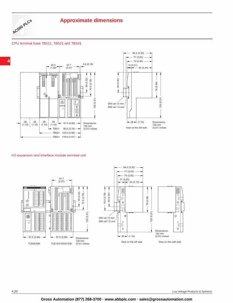
I/O expansion and interface module terminal unit
CPU terminal base TB511, TB521 and TB541
Approximate dimensions
Gross Automation (877) 268-3700 · www.abbplc.com · [email protected]

4
4AC500 PLCs
Low Voltage Products & Systems 4.21
Lloyd´s
Register Of
Shipping
Like all ABB products, the AC500 components, are as well tested in conformity with the applicable European, North American and international guidelines, and approved by the organizations responsible. These include GL, DNV, BV, RiNA, LRS and cUL. The products bear the CE symbol.
Certified quality
The entire process involved in creating an ABB product – from the original idea to the actual sale – is, of course, monitored by a quality management process certified under DIN ISO 9001.
In harmony with the natural environment
Protection of the natural environment is integral to ABB’s cor-porate philosophy. This includes both resource-economy and the avoidance of problematical substances, plus recycling-friendly construction and long-lived products. These aspects are taken fully on board by an integrated eco-management system conforming to ISO 14001, whose implementation is repeat-edly verified by regular eco-audits. And for newly developed products ABB now conducts a lifecycle assessment as well.
AC500 approvals
cUL, USA, Canada GL, Germany DNV, Norway BV, France RINa, Italy LRS, United Kingdom
Approvals
Gross Automation (877) 268-3700 · www.abbplc.com · [email protected]

4
4
4.22 Low Voltage Products & Systems
AC500 PLCs Notes
Gross Automation (877) 268-3700 · www.abbplc.com · [email protected]
Sales Information:Gross Automation1725 South Johnson Rd.New Berlin, WI 53146Telephone 262-446-0000Fax 262-446-0300http://www.abbplc.com
Pub
licat
ion
LV 0
20N
o. 1
SX
U 0
00 0
20 C
0202
Prin
ted
in U
SA
, May
, 200
6
Gross Automation (877) 268-3700 · www.abbplc.com · [email protected]