Application Note 44 - Digi...
26
1 Application Note 44 Using a TransPort router with DialServ in Protocol Switch mode Tech. Support September 2016
Transcript of Application Note 44 - Digi...

1
Application Note 44 Using a TransPort router with DialServ in
Protocol Switch mode
Tech. Support
September 2016

2
Contents
1 Introduction .............................................................................................................................. 3
1.1 Outline .............................................................................................................................. 3
1.2 Assumptions ...................................................................................................................... 5
1.3 Corrections ........................................................................................................................ 5
1.4 Version .............................................................................................................................. 5
2 Scenario .................................................................................................................................... 6
3 Configure the Cellular Interface ................................................................................................. 7
3.1 Configure the Cellular WAN Interface ................................................................................ 7
4 Configuration of PSTN Answering Mode ................................................................................... 9
4.1 DialServ Configuration ...................................................................................................... 9
4.2 Disconnect the DialServ ASY Port from PPP .................................................................... 10
5 Configuration of the Protocol Switch ....................................................................................... 11
5.1 Configure the Default Protocol Switching Method and Remote Host ............................... 11
5.2 Optional: Specify the Remote Host, Depending on the PSTN Number Dialled ................ 12
6 Allow Inbound TCP Connections and Forward to the PSTN Modem ........................................ 14
6.1 Configuration of the Protocol Switch ............................................................................... 14
6.2 Configure Listening TCP Ports ..........................................................................................15
7 Troubleshooting with the Protocol Switch ............................................................................... 17
7.1 Specifying the V. Mode of the DialServ Modem ............................................................... 19
7.2 Using Confirm Mode ........................................................................................................ 21
8 Configuration Files .................................................................................................................. 22
8.1 Digi TransPort Command Line Configuration .................................................................. 22
8.2 Digi TransPort Firmware Versions ................................................................................... 24

3
1 INTRODUCTION
1.1 Outline
The DialServ daughter card hardware option expands the functionality of a TransPort router so it
can appear as a PSTN line to a PSTN modem. This can be extremely useful when an application can
only use a PSTN modem but alternative (faster & cheaper) methods of routing the data are
available. The TransPort router will answer the incoming PSTN call from the directly attached
modem and route the data via the cellular (or any other WAN) interface to a specified destination or
just to the Internet depending on the application and project requirements.
The DialServ hardware will provide a dial tone to the connected PSTN device and answer calls
regardless of the number the PSTN device dials, so no changes need making to the modem
configuration.
It is even possible to replace an end to end PSTN solution by using 2 TransPort routers connected
over IP. One modem can dial up to its own locally attached TransPort router which forwards the
data via IP and the other (remote) TransPort router receiving the IP connection, dialling its own
locally attached PSTN modem. The data is transferred between the 2 modems as if a PSTN line was
being used.
If the application or hardware is serial based and not IP aware, the TransPort router can encapsulate
the data in a TCP or UDP data packet (or X.25 if applicable) before forwarding the data to its
configured destination.

4

5
1.2 Assumptions
This guide has been written for use by technically competent personnel with a good understanding
of the communications technologies used in the product, and of the requirements for their specific
application.
Configuration: This Application Note assumes the devices are set to their factory default
configurations. Most configuration commands are only shown if they differ from the factory
default.
This application note applies to;
Models shown: Digi TransPort WR41 router with the DialServ hardware option.
Other Compatible Models: All other Digi TransPort products with a DialServ daughter card.
Firmware versions: 5130 or newer
Please note: This application note has been specifically rewritten for firmware release 5.123 and
later but the original application note was testing and working for routers running earlier firmware
and the previous GUI. Routers running earlier firmware will find that the screen shots do not
accurately reflect what will be seen on those older routers. Contact [email protected] if you
require this document for the older GUI.
1.3 Corrections
Requests for corrections or amendments to this application note are welcome and should be
addressed to: [email protected]
Requests for new application notes can be sent to the same address.
1.4 Version
Version Number Status
1.0 Published
1.1 Updated for new GUI

6
2 SCENARIO
For the purposes of this application note, the following scenario will be used.
The monitoring servers also have the ability to open socket to the TransPort router’s public IP
address, when this happens, the TransPort will initiate a PSTN call to the electric meter and once
the connection is up, serial data will be forwarded to the meter.

7
3 CONFIGURE THE CELLULAR INTERFACE
This section assumes the WR41 is using a GSM/UMTS W-WAN module. For CDMA modules
additional steps will be required.
3.1 Configure the Cellular WAN Interface
Configuration - Network > Interfaces > Mobile
Parameter Setting Description
Settings on this page apply
to the selected SIM
SIM 1 (PPP 1) The following config will apply to
SIM 1 & PPP 1
Configuration - Network > Interfaces > Mobile > Mobile Settings
8
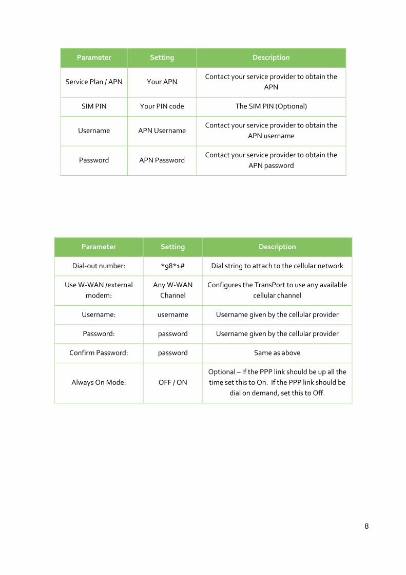
Parameter Setting Description
Service Plan / APN Your APN Contact your service provider to obtain the
APN
SIM PIN Your PIN code The SIM PIN (Optional)
Username APN Username Contact your service provider to obtain the
APN username
Password APN Password Contact your service provider to obtain the
APN password
Parameter Setting Description
Dial-out number: *98*1# Dial string to attach to the cellular network
Use W-WAN /external
modem:
Any W-WAN
Channel
Configures the TransPort to use any available
cellular channel
Username: username Username given by the cellular provider
Password: password Username given by the cellular provider
Confirm Password: password Same as above
Always On Mode: OFF / ON
Optional – If the PPP link should be up all the
time set this to On. If the PPP link should be
dial on demand, set this to Off.

9
4 CONFIGURATION OF PSTN ANSWERING MODE
4.1 DialServ Configuration
The first step is to configure the DialServ PSTN settings.
Browse to Configuration - Network > Interfaces > DialServ
Ensure Protocol Switch is used when the external modem connects to the TransPort, select the
Protocol Switch option, not PPP.
The ‘Max time to RING line’ parameter is the number of seconds before an outgoing call from the
TransPort to the PSTN modem is cleared if unanswered.
Most modems use a RING frequency of 20Hz. If the modem connected to the TransPort uses a
different RING frequency, change the value to match, otherwise leave it set at 20Hz.
If any extra modem initialisation strings are required, they can be entered into the bottom 2 boxes.
These will be sent to the DialServ card before a PSTN call is initiated.
Parameter Setting Description
Use Protocol Switch Selects Protocol Switch mode of operation
RING frequency
(Hz) 20
This needs to match the expected RING
frequency of the connected PSTN modem
Initialisation
strings AT commands
Extra initialisation strings to be sent to the
DialServ

10
4.2 Disconnect the DialServ ASY Port from PPP
Using Telnet, or a Serial connection, or the Execute a command GUI option, run the CLI command
modemcc 1 asy_add 255
This will remove the association between the DialServ modem and the ASY port the PPP interface
would normally use. The DialServ modem is normally connected on ASY 1 when in PPP mode, this
needs changing so that the serial data can be presented to the protocol switch for encapsulation.
Parameter Setting Description
modemcc 1 asy_add 255 The ASY port number for DialServ to use in
PPP mode
Save the current configuration to flash.

11
5 CONFIGURATION OF THE PROTOCOL SWITCH
5.1 Configure the Default Protocol Switching Method and Remote Host
The TransPort router can direct the DialServ data to a different host or via a different protocol (e.g.
TCP/UDP/X.25), depending on the PSTN number dialled by the meter.
The following configuration should be applied in all cases, even if the solution requires that there
are 2 or more remote hosts terminating the IP connection. This will ensure that even if the meter’s
PSTN modem dials up to the DialServ modem with an unknown number, the IP data stream will still
be forwarded to the remote host specified below.
If there is only 1 remote host terminating the IP connection, this step is required but 5.2 can be
skipped.
Browse to Configuration - Network > Protocol Switch
Click on the dropdown option to the right of ‘DSVR’, this will display the options for the protocol
switch, select the option you require. In this example, the data will be switched from raw serial data
on the DialServ modem to a TCP Stream.

12
Click TCP Stream to select it, then scroll down and enter the IP address and TCP port number of the
remote device that will either terminate or forward this TCP socket. In this example, the IP address
entered is the one assigned to the firewall/router serving ‘Monitoring Server 1’.
Parameter Setting Description
DSVR TCP Stream The protocol that raw serial data will be
encapsulated in.
IP stream or XoT
remote IP address IP address
The IP address of the remote host
terminating this socket
IP Stream port 0 - 65535 This needs to match the listening port
number used by the remote host.
5.2 Optional: Specify the Remote Host, Depending on the PSTN Number
Dialled
The TransPort router can direct the TCP/UDP/X.25 encapsulated traffic to a different host,
depending on the PSTN number dialled by the meter.
If there is only 1 remote host terminating the IP connection, this step is not required.
In this example, there are 2 remote hosts, each was dialled on a PSTN number before the TransPort
router was installed. This section is where the phone number to IP address mapping is configured.

13
Browse to Configuration - Network > Protocol Switch > NUA to Interface Mappings
In the top line, enter the settings for connecting to ‘Monitoring server 1’. Then click Add.
The PSTN number previously dialled by the modem should be entered into the NUA field, followed
by the remote IP address and port that this number will be mapped to.
In the next line down, enter the connection details for ‘Monitoring server 2’. Click Add.
Click Apply and Save the configuration to flash.
Parameter Setting Description
NUA PSTN number Number dialled by the PSTN modem in the
meter
IP Address IP address The IP address of the remote host that the
phone number should be mapped to.
IP Port 0 - 65535 This needs to match the listening port
number used by the remote host.

14
6 ALLOW INBOUND TCP CONNECTIONS AND FORWARD TO
THE PSTN MODEM
It is also possible to allow the remote servers to initiate a TCP connection to the TransPort’s public
IP address of 80.3.19.103 on TCP port 10502. When connection is opened to the configured socket,
the data will be de-capsulated, the DialServ modem will send a RING signal to the attached PSTN
modem in the meter. The meter’s PSTN modem will answer and when the link has trained up, the
raw serial data will be forwarded to the meter. This allows for polling and configuration of the
meter by a server initiated connection.
6.1 Configuration of the Protocol Switch
Configure the protocol switch to forward TCP connections to the DialServ modem.
Browse to Configuration - Network > Protocol Switch
Click on the dropdown option to the right of ‘TCP or XoT or SSL’, this will display the options for the
protocol switch, select the option you require. In this example, the data will be switched from TCP
to DialServ and the serial data will be forwarded to the meter’s PSTN modem.
Parameter Setting Description
TCP or XoT or SSL DSRV The protocol that TCP data will be switched
to.
15
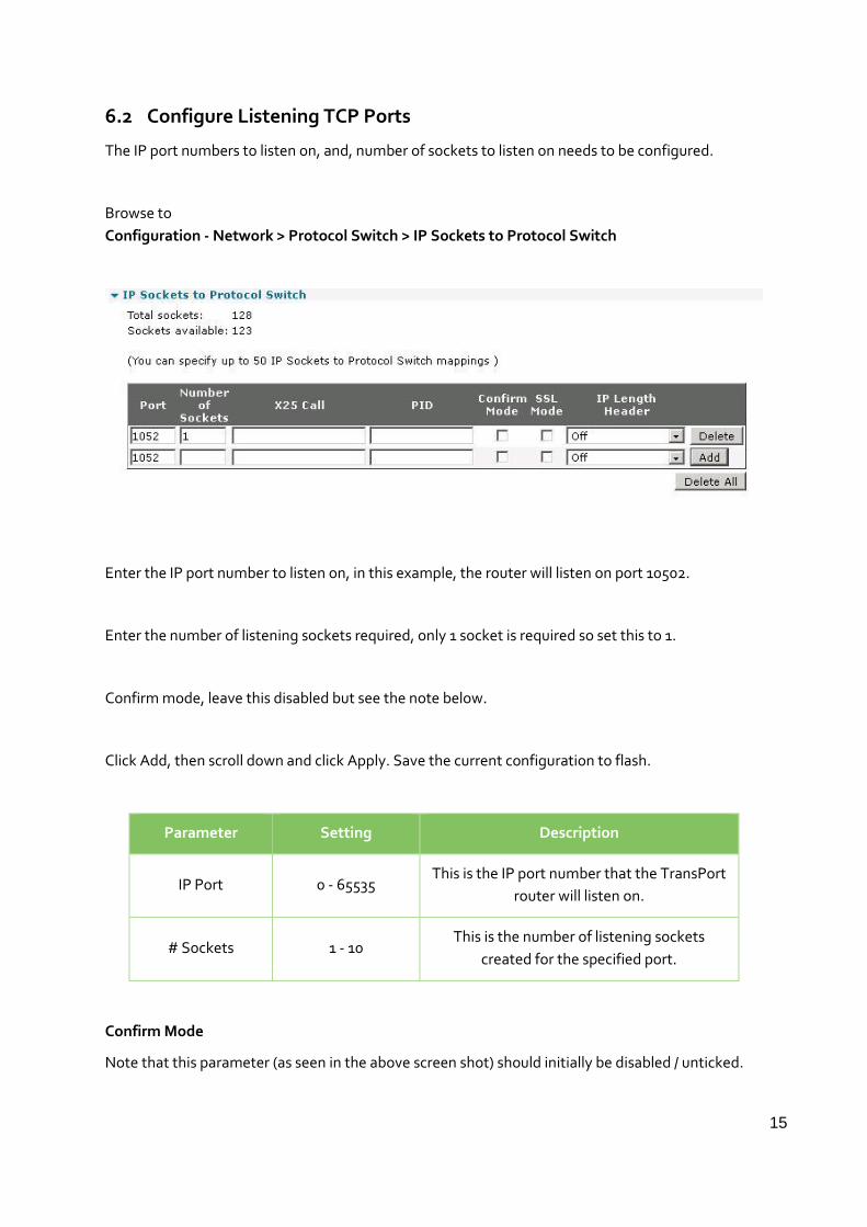
6.2 Configure Listening TCP Ports
The IP port numbers to listen on, and, number of sockets to listen on needs to be configured.
Browse to
Configuration - Network > Protocol Switch > IP Sockets to Protocol Switch
Enter the IP port number to listen on, in this example, the router will listen on port 10502.
Enter the number of listening sockets required, only 1 socket is required so set this to 1.
Confirm mode, leave this disabled but see the note below.
Click Add, then scroll down and click Apply. Save the current configuration to flash.
Parameter Setting Description
IP Port 0 - 65535 This is the IP port number that the TransPort
router will listen on.
# Sockets 1 - 10 This is the number of listening sockets
created for the specified port.
Confirm Mode
Note that this parameter (as seen in the above screen shot) should initially be disabled / unticked.
16
Confirm mode ensures that end-to-end connectivity has been established before the listening
socket answers to the remote devices connection request.
When confirm mode is enabled, the TransPort router will detect the inbound connection on port
10502, but will not reply. The remote server should keep trying to connect, this is normal TCP/IP
operation. The DialServ will send a RING to the attached PC’s PSTN modem, which will answer and
train up. Once the link is established between the 2 PSTN modems, the TransPort router will
answer the next socket connection attempt from the remote device and the received data will be
forwarded to the PC.
If the remote devices have difficulty establishing a connection with the PC, enable ‘Confirm Mode’.

17
7 TROUBLESHOOTING WITH THE PROTOCOL SWITCH
It is often useful to trace the serial connection to the Digi TransPort DialServ modem:
Browse to Management - Analyser > Settings. Enable the “DialServ” Serial Interfaces source.
Clear the analyser trace, attempt a connection, view the analyser trace:
Browse to Management - Analyser > Trace
Read this in conjunction with the eventlog, the eventlog will show inbound/outbound TCP
connection attempts:
Browse to Management - Event Log
This is an example of an inbound TCP connection from Monitoring server 2 failing:
The following eventlog shows an incoming TCP connection (read from the bottom up):
10:52:56, 05 May 2010,XSW 0 Clearing X25 call
10:52:56, 05 May 2010,XSW 26 X25 Deactivated DialServ connection lost
10:52:56, 05 May 2010,XSW 26 X25 Call gone,socket closed TCP socket closed
10:51:26, 05 May 2010,1 X25 Calls per sec Dial serve connection attempt in progress
10:51:25, 05 May 2010,XSW 26 X25 Call req #: 567 Protocol switch initiating DialServ modem
connection
10:51:25, 05 May 2010,XSW 0 Inc X25 call #: Protocol switch acknowledging it has an
incoming call
10:37:25, 05 May 2010,GP socket connected: 80.3.19.103:10502 -> 56.22.1.5:3011 TCP
connection established
The following ana trace shows the interface between the Digi TransPort main board and DialServ
interface (daughter card):
----- 5-5-2010 10:37:25.150 -------
ASY 1 DTE to DCE:
0D 0A 52 49 4E 47 0D 0A ..RING..
----------
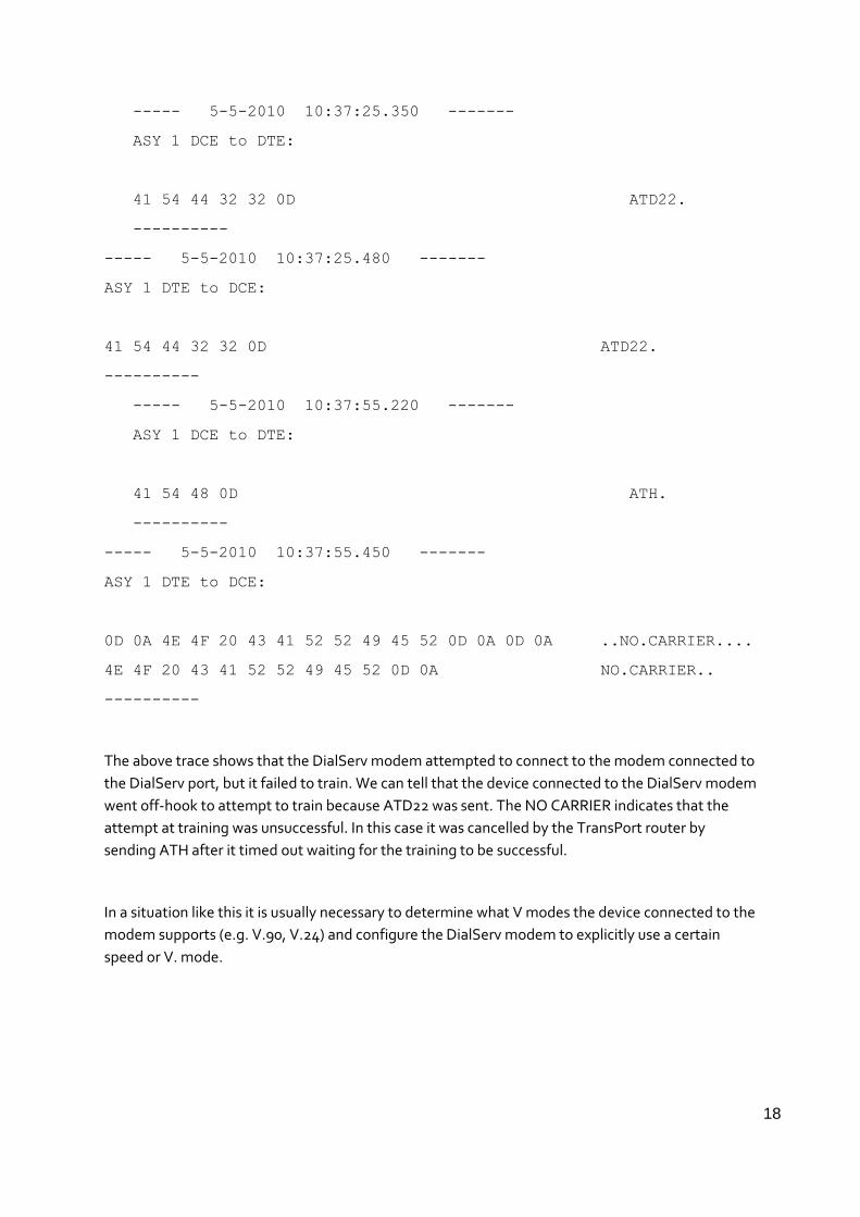
18
----- 5-5-2010 10:37:25.350 -------
ASY 1 DCE to DTE:
41 54 44 32 32 0D ATD22.
----------
----- 5-5-2010 10:37:25.480 -------
ASY 1 DTE to DCE:
41 54 44 32 32 0D ATD22.
----------
----- 5-5-2010 10:37:55.220 -------
ASY 1 DCE to DTE:
41 54 48 0D ATH.
----------
----- 5-5-2010 10:37:55.450 -------
ASY 1 DTE to DCE:
0D 0A 4E 4F 20 43 41 52 52 49 45 52 0D 0A 0D 0A ..NO.CARRIER....
4E 4F 20 43 41 52 52 49 45 52 0D 0A NO.CARRIER..
----------
The above trace shows that the DialServ modem attempted to connect to the modem connected to
the DialServ port, but it failed to train. We can tell that the device connected to the DialServ modem
went off-hook to attempt to train because ATD22 was sent. The NO CARRIER indicates that the
attempt at training was unsuccessful. In this case it was cancelled by the TransPort router by
sending ATH after it timed out waiting for the training to be successful.
In a situation like this it is usually necessary to determine what V modes the device connected to the
modem supports (e.g. V.90, V.24) and configure the DialServ modem to explicitly use a certain
speed or V. mode.

19
7.1 Specifying the V. Mode of the DialServ Modem
AT&H6 (For v22bis)
AT&G7 (For v22)
Make an appropriate entry on the Configuration - Network > Interfaces > DialServ “Initialisation
string 1:” parameter to specify the mode that will match the PSTN modem in the meter. For
example:
&Gn - Reduction of data transmission speed
&G4 - 2.4 kbps max
&G5 - 4.8 kbps max.
&G6 - 7.2 kbps max.
&G7 - 9.6 kbps max.
&G8 - 12 kbps max.
&G9 - 14.4 kbps max
&G10 - 16.8 kbps max.
&G11 - 19.2 kbps max.
&G12 - 21.6 kbps max.
&G13 - 24 kbps max.
&G14 - 26.4 kbps max.
&G15 - 28.8 kbps max.
&G16 - 31.2 kbps max.
&G17 - 33.6 kbps max.

20
&Hn -Selection of data transmission format
&H0 - V.90 with automatic speed reduction (from 56 kbps to 300bps)
&H1 - V.90 only (from 56 kbps to 28 kbps)
&H2 - V.34 with automatic speed reduction (from 33.6 kbps to 300bps)
&H3 - V.34 only (from 33.6 kbps to 2400 bps)
&H4 - ITU-T V.32bis with automatic speed reduction (from 14.4 kbps to 300 bps)
&H5 - ITU-T V.32bis only (from 14.4 kbps to 4800 bps)
&H6 - ITU-T V.22bis only (2400 kbps to 1200 bps)
&H7 - ITU-T V.22 only (1200 bps)
&H8 - Bell 212 only (1200 bps)
&H9 - Bell 103 only (300bps)
&H10 - ITU-T V.21 only (300 bps)
&H11 - V.23 (1200/75 bps)
21
7.2 Using Confirm Mode
Another common problem can occur when using inbound TCP sockets is if the TCP initiator starts to
send data as soon as the TCP connection is established. Any data sent after the TCP connection has
been established but before the modems have trained up will be lost. It is possible to work around
this by enabling the “Confirm Mode” parameter on the “Configuration - Network > Protocol
Switch > IP Sockets to Protocol Switch” web page. This will prevent the Digi TransPort from
acknowledging the TCP connection attempt until the modems have trained up, thus as soon as the
TCP connection is established it is safe to send data and it will not be lost. The disadvantage of this
option is that it may take longer for the modems to train up than the initiator of the TCP connection
is prepared to wait for the TCP connection attempt to be successful. There are two workarounds for
such a problem:
1) Tweak the initialisation strings to train up in a slow vmodem such as V.22. Typically this will train much quicker than a higher V mode such as V.90. Preferably also configure the device connected to the DialServ port to use the same V mode so that no time is lost attempting to negotiate to use different V modes.
2) By some means tweak the TCP stack on the initiator so that it waits longer for the TCP connection to be established

22
8 CONFIGURATION FILES
8.1 Digi TransPort Command Line Configuration
Only the relevant parts of the configuration file that specifically relate to the configuration of this
example will be explained.
The Digi TransPort’s Ethernet IP address:
eth 0 IPaddr “10.1.51.254” eth 0 mask “255.255.255.0”
Cellular Module configuration when using UMTS/WCDMA:
modemcc 0 apn “internet”
DialServ modem configuration:
pots 0 dsvr_protsw ON pots 0 ring_secs 4 pots 0 ring_freq 20
Default route configuration:
def_route 0 ll_ent “PPP” def_route 0 ll_add “1”
PPP 1 configuration (Cellular interface):
ppp 1 IPaddr "0.0.0.0" ppp 1 username "vodafone" ppp 1 epassword "Ozt7Ww==" This is the encrypted version of the PPP 1 password ppp 1 phonenum "*98*1#" ppp 1 name "Cellular PPP link" ppp 1 timeout 0 ppp 1 use_modem 1 ppp 1 aodion 1 ppp 1 pwr_dly 20 ppp 1 autoassert 1 In this example, Always on mode is On
Internal ASY port connection between DialServ and router, PPP is disconnected:
modemcc 1 asy_add 255
Default protocol switch configuration, outbound to remote host:
x25sw 0 IPaddr "56.22.1.4" x25sw 0 ip_port 10501 x25sw 0 swfrpots 9
Phone number to remote host IP address and port mapping when multiple remote hosts are
defined:
nuaip 0 nua "0123456666" nuaip 0 IPaddr "56.22.1.4" nuaip 0 ip_port 10501 nuaip 1 nua "0123457777" nuaip 1 IPaddr "56.22.1.5"

23
nuaip 1 ip_port 10501
Protocol switch configuration, inbound TCP connections from remote servers:
x25sw 0 swfrxot 16
Listening sockets for inbound TCP connections from servers:
ipx25 0 ip_port 10502 ipx25 0 nb_listens 1

24
8.2 Digi TransPort Firmware Versions
The Digi TransPort configuration above was tested on a Digi TransPort WR41 with firmware version
5.2.15.6
Digi TransPort WR41-U8P3-WE1-XX(WR41v2) Ser#:131926 HW Revision: 32021
Software Build Ver5.2.15.6. Aug 17 2016 17:42:02 MW
ARM Bios Ver 7.56u v41 399MHz B256-M256-F80-O140,0 MAC:00042d020356
Power Up Profile: 0
Async Driver Revision: 1.19 Int clk
Wi-Fi Revision: 2.0
Ethernet Driver Revision: 1.11
Firewall Revision: 1.0
EventEdit Revision: 1.0
Timer Module Revision: 1.1
(B)USBHOST Revision: 1.0
L2TP Revision: 1.10
PPTP Revision: 1.00
TACPLUS Revision: 1.00
MODBUS Revision: 0.00
POTS Revision: 0.01
RealPort Revision: 0.00
MultiTX Revision: 1.00
LAPB Revision: 1.12
X25 Layer Revision: 1.19
MACRO Revision: 1.0
PAD Revision: 1.4
X25 Switch Revision: 1.7
V120 Revision: 1.16
TPAD Interface Revision: 1.12
GPS Revision: 1.0
TELITUPD Revision: 1.0

25
SCRIBATSK Revision: 1.0
BASTSK Revision: 1.0
PYTHON Revision: 1.0
CLOUDSMS Revision: 1.0
ARM Sync Driver Revision: 1.18
TCP (HASH mode) Revision: 1.14
TCP Utils Revision: 1.13
PPP Revision: 5.2
WEB Revision: 1.5
SMTP Revision: 1.1
FTP Client Revision: 1.5
FTP Revision: 1.4
IKE Revision: 1.0
PollANS Revision: 1.2
PPPOE Revision: 1.0
BRIDGE Revision: 1.1
MODEM CC (GOBI UMTS) Revision: 5.2
FLASH Write Revision: 1.2
Command Interpreter Revision: 1.38
SSLCLI Revision: 1.0
OSPF Revision: 1.0
BGP Revision: 1.0
QOS Revision: 1.0
PWRCTRL Revision: 1.0
RADIUS Client Revision: 1.0
SSH Server Revision: 1.0
SCP Revision: 1.0
SSH Client Revision: 1.0
CERT Revision: 1.0
LowPrio Revision: 1.0
Tunnel Revision: 1.2
OVPN Revision: 1.2

26
QDL Revision: 1.0
OK