APPENDIX S FRAMEWORK SPILL PREVENTION AND RESPONSE...
17
APPENDIX S FRAMEWORK SPILL PREVENTION AND RESPONSE PLAN
Transcript of APPENDIX S FRAMEWORK SPILL PREVENTION AND RESPONSE...

APPENDIX S FRAMEWORK SPILL PREVENTION AND
RESPONSE PLAN

TransWest Express Transmission Project
PLAN OF DEVELOPMENT – APPENDIX S PAGE i
TABLE OF CONTENTS
S1.0 INTRODUCTION .................................................................................................................... 1
S2.0 PLAN PURPOSE...................................................................................................................... 1
S3.0 PLAN UPDATES...................................................................................................................... 1
S4.0 RESPONSIBILITY OF PLAN IMPLEMENTATION ......................................................... 1
S5.0 GENERAL PETROLEUM PRODUCTS, QUANTITIES, AND STORAGE .................... 1
S6.0 SPILL PREVENTION MEASURES ...................................................................................... 2
S6.1 OIL TRANSFER OPERATIONS .................................................................................................. 2 S6.1.1 Hydraulic and Lubricating Oils ...................................................................................... 2 S6.1.2 Diesel Fuel and Gasoline ................................................................................................ 2
S6.2 SECONDARY CONTAINMENT AND/OR DIVERSIONARY STRUCTURES ..................................... 3 S6.3 INSPECTIONS AND PERSONNEL TRAINING .............................................................................. 3
S6.3.1 Inspections ...................................................................................................................... 3 S6.3.2 Personnel Training .......................................................................................................... 4
S7.0 SPILL CONTROL AND COUNTERMEASURES ............................................................... 4
S8.0 AGENCY NOTIFICATION .................................................................................................... 5
S8.1 EMERGENCY CONTACTS ......................................................................................................... 5
S9.0 ENVIRONMENTAL PROTECTION .................................................................................... 6
TABLES: TABLE S1 FEDERAL AND STATE EMERGENCY CONTACTS ............................................................... 5 APPENDICES: ATTACHMENT A TYPICAL SPILL CONTAINMENT MEASURES ....................................................... 7

TransWest Express Transmission Project
PLAN OF DEVELOPMENT – APPENDIX S PAGE ii
ACRONYMS Applicant TransWest Express LLC, also TransWest BLM Bureau of Land Management BMP Best Management Practice CFR Code of Federal Regulations CSU Controlled Surface Use DEIS Draft Environmental Impact Statement EMM Environmental Mitigation Measure EPA United States Environmental Protection Agency FEIS Final Environmental Impact Statement NSU No Surface Use NTP Notice to Proceed Plan Spill Prevention and Response Plan POD Plan of Development Project TransWest Express Transmission Project, also TWE Project ROD Record of Decision ROW right-of-way SPCC Plan Spill Prevention, Control, and Countermeasure Plan TransWest TransWest Express LLC, also Applicant TWE Project TransWest Express Transmission Project, also Project USDOT United States Department of Transportation USFS United States Forest Service WWEC West-wide Energy Corridor
TransWest Express Transmission Project
PLAN OF DEVELOPMENT – APPENDIX S PAGE 1
S1.0 INTRODUCTION This framework Spill Prevention and Response Plan (Plan) identifies the specific stipulations and methods that TransWest Express LLC (TransWest or Applicant) and its Construction Contractor(s) will follow to address spill prevention, response, and cleanup for the TransWest Express Transmission Project (TWE Project or Project). In conjunction with this framework Plan, TransWest developed a framework Hazardous Materials Management Plan (Appendix L), which identifies specific measures that TransWest and its Construction Contractor(s) will take to reduce the risks associated with the use, storage, transportation, and disposal of hazardous materials. S2.0 PLAN PURPOSE The purpose of this Plan is to prevent hazardous material spills from Project facilities entering into water bodies. The Construction Contractor(s) shall use the following framework to develop the Spill Prevention and Response Plan, which differs from a Spill Prevention, Control, and Countermeasure (SPCC) Plan which is required for facilities that store more than 1,320 gallons of oil. For Project facilities that store more than 1,320 gallons of oil in containers with shell capacities of 55 gallons or greater, a SPCC Plan will be developed in accordance with Title 40 Code of Federal Regulations (CFR) Part 112. The following framework describes measures that the Construction Contractor(s) shall use to prevent, respond to, and control spills of hazardous materials, as well as measures to minimize a spill’s effect on the environment. S3.0 PLAN UPDATES This Plan will be updated for the Record of Decision (ROD) Plan of Development (POD) and will include relevant mitigation measures to ensure regulation compliance and safety. The Plan for the Notice to Proceed (NTP) POD will include updates as needed based on the final design and engineering and a complete and up-to-date emergency contact list. The Construction Contractor(s) will be responsible for preparing and implementing the final Plan in compliance with local, state, and federal regulations pertaining to spill prevention and response. S4.0 RESPONSIBILITY OF PLAN IMPLEMENTATION TransWest, through its Construction Contractor(s) and inspectors, shall be responsible for implementing the Plan. The Construction Contractor(s) shall comply with applicable federal, state, and local regulations for using, storing, and disposing of hazardous materials, as well as for oil transfer operations. S5.0 GENERAL PETROLEUM PRODUCTS, QUANTITIES, AND
STORAGE During construction activities, the Construction Contractor(s) would use various petroleum products. Typical fuels used for the Project include diesel fuel and gasoline. Typical lubricants for the Project include engine oil, transmission/drive train oil, hydraulic oil, gear oil, and general lubricating grease. Typical coolants include glycols such as anti-freeze. The quantity of fuel storage will vary generally from 500 to 1,000 gallons in aboveground storage tanks at designated construction yards. The aboveground storage tanks will be equipped with secondary containment sized to contain the largest volume of fuel and provide sufficient freeboard. Fuel trucks will be used to transport large quantities of fuel. Smaller quantities of fuel, five to 100

TransWest Express Transmission Project
PLAN OF DEVELOPMENT – APPENDIX S PAGE 2
gallons, may sometimes be stored temporarily in the construction area along the right-of-way (ROW). Pickup trucks will be used to transport these smaller quantities of fuel. Lubricants and coolants will be stored in bulk or retail packaging at contractor yards in quantities typically less than 500 gallons and transported in trucks to the construction area as needed. S6.0 SPILL PREVENTION MEASURES The following describes various spill prevention measures that the Construction Contractor(s) shall implement to reduce the potential for a spill to occur in accordance with Applicant Committed Environmental Mitigation Measure (EMM) TWE-57. The measures include conducting oil transfer operations in accordance with applicable oil pollution prevention and safety requirements, and conducting periodic inspections and personnel training. S6.1 Oil Transfer Operations S6.1.1 Hydraulic and Lubricating Oils The hydraulic and lubricating oils in construction vehicles are typically replenished or replaced on an infrequent basis. It is expected that the hydraulic and lubricating oils would be handled using containers, each of which would have a shell capacity of less than 55 gallons. S6.1.2 Diesel Fuel and Gasoline It is expected that vendors would use tank trucks to deliver diesel fuel and gasoline to aboveground storage tanks, where construction vehicles would refuel. When tank truck loading/unloading operations occur, Construction Contractor personnel shall ensure that procedures at the site meet the minimum requirements and regulations established by the U.S. Department of Transportation (USDOT). Fuel transfer operations shall occur through aboveground unloading hoses, which shall be supported and designed to minimize abrasion during transfer operations. To prevent vehicles from departing before disconnection of the transfer hose, spill prevention techniques provide for:
• The setting up of barriers or warning signs to prevent a truck from leaving before the completion of unloading.
• Placing wheel chocks on truck tires to prevent vehicle movement during unloading.
• Closely inspecting the lowermost drain and all outlets for discharges.
• Ensuring truck drains/outlets are tightened, adjusted, or replaced as needed.
The Construction Contractor(s) shall take the following measures to prevent spills prior to, during, and after unloading:
• Prior to unloading: Fuel levels shall be verified, connections rechecked, and hoses examined for integrity. Signs shall be posted warning all vehicular traffic operating in the transfer area to use caution.
• During unloading: Only trained personnel authorized to conduct the transfer shall be utilized. The transfer and pumping system shall be continually monitored for leaks and the fuel level in the receiving container shall be frequently monitored to prevent overfilling.

TransWest Express Transmission Project
PLAN OF DEVELOPMENT – APPENDIX S PAGE 3
• After unloading: The transfer hose shall be properly drained and disconnected, and all tank truck drains and connections shall be checked for proper closure prior to departure.
Vehicle refueling and servicing activities will be performed in designated construction zones located more than 100 feet from wetlands and intermittent streams and more than 500 feet from perennial steams in accordance with Applicant Committed EMM TWE-24. If unique conditions require refueling within 100 feet of a water body, wetland, or within designated municipal watersheds, a determination of necessary emergency response actions shall be conducted prior to refueling activities. Additionally, absorbent materials or other spill containment materials shall be available for immediate application prior to commencing refueling activities. Fuel trucks transporting fuel to on-site equipment shall travel only on approved access roads. Each construction crew shall have readily available and sufficient supplies of absorbent, barrier materials and USDOT-approved containers to allow for rapid containment and recovery of any spill of hazardous material. S6.2 Secondary Containment and/or Diversionary Structures All hazardous materials containing equipment that has the potential to discharge to water bodies shall be equipped with secondary containment or other appropriate prevention measures. The Construction Contractor(s) shall develop oil transfer/unloading procedures (section S6.1) and have spill response materials available that can be used to immediately respond to a discharge, should an incident occur.. S6.3 Inspections and Personnel Training S6.3.1 Inspections The Construction Contractor(s) shall conduct weekly inspections of oil-containing equipment and facilities. These inspections shall include the items below, as applicable, and be recorded either with paper inspection forms or electronically:
• Container foundation
• Container shell condition
• Tank level control
• Piping condition
• Piping supports
• Piping flange or expansion joints
• Piping valve glands and bodies
• Locking of valves
• Oil levels
• Oil gauges
• Oil leaks of any type
• Stains and accumulated free product on the ground

TransWest Express Transmission Project
PLAN OF DEVELOPMENT – APPENDIX S PAGE 4
S6.3.2 Personnel Training The Construction Contractor’s personnel shall receive hazardous material awareness training in accordance with Applicant Committed EMM TWE-57. More specifically, prior to the start of construction activities, the Construction Contractor(s) shall train hazardous material-handling personnel on methods to prevent, control, and respond to a hazardous material spill. Newly hired personnel who work in facilities where hazardous materials are stored shall be informed of storage locations and the emergency plan procedure in the event of an accidental spill. New personnel who work with hazardous materials shall be trained in the proper management of those materials under normal operating circumstances and under emergency circumstances. Hazardous material-handling personnel shall be trained on the following topics:
• Operation and maintenance of equipment to prevent discharges
• Applicable state and federal laws, rules, and regulations
• Spill reporting procedures
• Spill containment and recovery procedures
• Storage of waste materials
• Safety and health considerations
• General facility operations
• Contents of the Spill Prevention and Response Plan
S7.0 SPILL CONTROL AND COUNTERMEASURES Should a spill occur, the Applicant and its Construction Contractor(s) shall commit the manpower, equipment, and materials necessary to respond to and control a hazardous material spill in accordance with Applicant Committed EMM TWE-57. Prior to construction, the Construction Contractor(s) shall submit an emergency preparedness and response plan. The plan shall comply with all applicable federal, state, and local regulations. The plan shall describe emergency response operations, including but not limited to, spill control, cleanup, notification, characterization, and disposal procedures. All contractor supervisors and personnel handling hazardous substances shall be familiar with these procedures. As part of the emergency preparedness and response plan, the Construction Contractor(s) shall establish procedures and individual responsibilities regarding spill discovery, response, clean-up, and disposal. Prior to beginning construction, the Construction Contractor(s) shall be required to submit a list of spill response contractors and commercial disposal facilities to TransWest for approval. Per West-wide Energy Corridor (WWEC) Best Management Practice (BMP) PHS-15 in the Draft Environmental Impact Statement (DEIS), hazardous material spills shall be removed and the affected area(s) cleaned to meet applicable standards. Per the Bureau of Land Management (BLM) Richfield Field Office’s No Surface Use (NSU) and Controlled Surface Use (CSU) restrictions for the Utah prairie dog, inadvertent spills of petroleum-based or other toxic materials shall be removed and the affected area(s) cleaned immediately.

TransWest Express Transmission Project
PLAN OF DEVELOPMENT – APPENDIX S PAGE 5
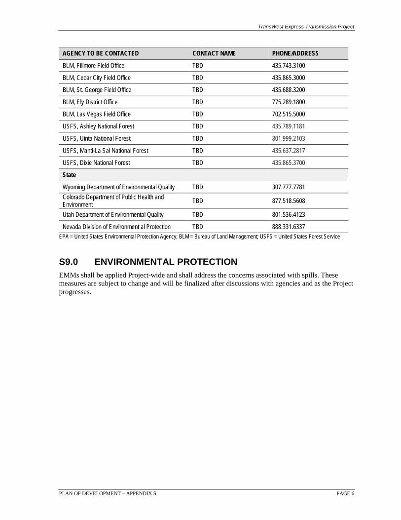
The emergency preparedness and response plan will describe measures to respond to and control hazardous material spills. Following a spill, all reasonable efforts shall be made to immediately control the source of the discharge and contain the spill. Absorbent materials shall be deployed with efforts directed to limiting the area of contamination. All reasonable efforts shall be made to prevent any spill from reaching wetlands or waterbodies. If a spill should reach surface waters, straw bales, booms, and absorbent materials shall be immediately deployed to contain and reduce downstream migration of the spilled material. Once a spill is contained, cleanup activities shall begin immediately. All spilled material, contaminated soil, and absorbent material shall be picked up and contained for disposal. In the event of a large spill or a spill that migrates into surface waters, the spill response contractors will be called to assist in cleanup efforts. Attachment A includes a list of typical spill containment measures S8.0 AGENCY NOTIFICATION S8.1 Emergency Contacts Any spill of any material in such quantity as may, with reasonable probability, injure or be detrimental to human health, animal, plant life, property, or may unreasonably interfere with the public welfare or the use of property will be reported. This includes chemical, biohazardous, petroleum-product, and sewage spills and incidents. In addition to recent spills, the discovery of evidence of previous unauthorized discharges, such as contaminated soil or groundwater, also must be reported. As soon as possible after beginning spill control and cleanup activities, the Construction Contractor(s) shall notify TransWest, who will determine if the spill is reportable. TransWest will notify the appropriate authorities of any reportable spills. In accordance with Applicant Committed EMM TWE-57, Table S1 lists the federal and state contacts that the Construction Contractor(s) shall notify in the event of a reportable hazardous material spill from a Project facility or construction site. The agencies listed are based on the jurisdictions crossed by the Agency Preferred and Applicant Proposed Alternatives in the Final Environmental Impact Statement (FEIS). In accordance with WWEC BMP PHS-13 in the DEIS, the Construction Contractor(s) shall document the spill and provide the documentation to the land management agency’s authorized officer. The Construction Contractor(s) shall also note the cause of the spill and note corrective measures taken to prevent another spill from occurring. TABLE S1 FEDERAL AND STATE EMERGENCY CONTACTS
AGENCY TO BE CONTACTED CONTACT NAME PHONE/ADDRESS
Federal
EPA Region 8 Emergency Response Center TBD 303.312.6312
EPA Region 9 Emergency Response Center TBD 415.947.8000
BLM, Rawlins Field Office TBD 307.328.4200
BLM, Little Snake Field Office TBD 970.826.5000
BLM, White River Field Office TBD 970.878.3800
BLM, Vernal Field Office TBD 435.781.4400
BLM, Price Field Office TBD 435.636.3600
BLM, Salt Lake Field Office TBD 801.977.4300
BLM, Richfield Field Office TBD 435.896.1500
TransWest Express Transmission Project
PLAN OF DEVELOPMENT – APPENDIX S PAGE 6
AGENCY TO BE CONTACTED CONTACT NAME PHONE/ADDRESS
BLM, Fillmore Field Office TBD 435.743.3100
BLM, Cedar City Field Office TBD 435.865.3000
BLM, St. George Field Office TBD 435.688.3200
BLM, Ely District Office TBD 775.289.1800
BLM, Las Vegas Field Office TBD 702.515.5000
USFS, Ashley National Forest TBD 435.789.1181
USFS, Uinta National Forest TBD 801.999.2103
USFS, Manti-La Sal National Forest TBD 435.637.2817
USFS, Dixie National Forest TBD 435.865.3700
State
Wyoming Department of Environmental Quality TBD 307.777.7781 Colorado Department of Public Health and Environment TBD 877.518.5608
Utah Department of Environmental Quality TBD 801.536.4123
Nevada Division of Environment al Protection TBD 888.331.6337 EPA = United States Environmental Protection Agency; BLM = Bureau of Land Management; USFS = United States Forest Service S9.0 ENVIRONMENTAL PROTECTION EMMs shall be applied Project-wide and shall address the concerns associated with spills. These measures are subject to change and will be finalized after discussions with agencies and as the Project progresses.

TransWest Express Transmission Project
PLAN OF DEVELOPMENT – APPENDIX S PAGE 7
ATTACHMENT A
TYPICAL SPILL CONTAINMENT MEASURES

_j_
• r I Bonneville Power AdministrationI ~
I I ., •• -I
r
r
-· .. ri# I •
0 0. :.-c;.Rock or French Drain •
Q ....... .t..>
m (made of Sand Bag or Plastic) that will block
the ow of Oil
Plan View
Side View
Dam (made of Sand Bags or Plastic) that will block
the flow of Oil
End View
Figure 14. Interceptor Trenching/French Drainage
Spilled Product
0
____.__
-... _I
Follow these procedures for cont.ammg 01ls spills utilizing Interceptor trenchmg
.... • Remove yard rock from drain downslope from spill .
Build earth or plastiC sheetimg dam on downslope side Pump or skim oil from hole.
- t.- I-· --=- .. -l
BPA Oil Spill Guidance
Interceptor Trenching/French Drainage Remove yard rock from the downslope side of the spill (Figure 14). Excavate an interceptor trench and line it with polyethylene. Use vacuum trucks to pump oil product from the collection depression. or portable skimmers in conjunction with storage containers (drums, dracons, tank trucks) Sorbent matting can be used ifeduction and/or skimming equipment is operationally unavailable or oily product in the coUection depression is mimmal
0 0
- - _I

~~~~~~'~oil Earthen Dam or
Sand Bagged Dam Water-
Side View
Sorbent Boom
Water
or Matting
Earthen Dam or Sand Bagged
Dam
Ditch Bank Sorbent Boom or Matting
Top View
Figure 15. Sandbag and Eart hen Dam s
II
•
Use Portable Skimmer,
BPA Oil Spill Guidan c e
Solid Dams for Drainage Dit ches, Cana ls, and Rivers (Less than I knot of current) Ifwater flow is non~xistcnt in a dJrainagc ditch, canal, or small river, and constructiOn equipment is avai lab le, earthen dams can be constructed to abate oily product movement. Sandbags can be used to reinforce or build an earthen dam (Figure 15) Lining the earthen dam with polyethylene can improve the impermeability of the earthen dam. Sorbcnt mattmg or boom and portable skimme rs can be used to remove the oily product from insid1e rhe dam
• Bonnieville Power Administration •
-I •
'

Stakes
Deploy Sorbent Boom Set at
s 20° Deflection Angle .. s- Current (1 - 3 Knots)
-- Deflected Oily Product
Sorbent Matting or Pads
Top View
Figure 19a. Sorbent Boom 1
- -----------
SPA Oil Spill Guidance
Sorbent Booms for Drainag~e Ditches, Canals, and Rivers (1·3 knots of current) Sorbent boom was designed to pr•ovide very llm1ted containmenJ or deflection capability, while absorbing oily product (Figure 191a). Sorbent boom is an operational compromise between flat sorbent matting and standard skirted cont'llinment boom. Flat sorbents offer the most surbce area for soalcing up oil, but have no containment or deflection capabilities. T~tional skirted oil boom cootains or deflects oily product, but absorbs nothing. A sorbent boom is most effective when used in conjunction with sorbent matting or pads, bur only in light currents. . Sorbent boom is available in 4, 8, 10, and 20 foot lengths and 4, 6, and 8 inch diameters.
Follow these instructions for using Sorbcnt Boom I :
• Use sorbent boom in pa1red lengths to assure rrunimal leakage. • Ifcurrent IS eVldcnt, assure deflection angle IS 20 degrees or less • Oily product will collect at apex of sorbcnt boom/shoreline angle. Use sorbcnt matting and pads,
or portable sk1mmers to clean oily product
Bonneville Power Administration

Stakes
- 3 Knots)
Deploy S orbent Boom Set at
S20° Deflection Angle .. s- Curr~nt (1
:.---- Deflected Oily Product
Portable Skimmer
Top View
Figure 19b. Sorbent Boom ~2
BPA Oil Spill Guidance
Sorbent Booms for Drainaqe Ditches, Canals, and Rivers (1-3 knots of current) Sorbent boom was designed to provide very limited containment or dejle~tion capability, while absorbing oily product (Figures 19b). Sorbent boom is an operational compromise between flat sorbent matting and standard skirted conta.U\ment boom. Flatsorbeots offer the most surface area for soaking up oil, but have no containment or detlectioo capabilitie.c;. Traditional skirted oil boom contains or deflects oily product, but absorbs n9thing. A sorbent boom is most effective when used in conjunction with sorbent matting: or pads, but only in light currents. Sorbent boom is available in 4, 8, 10, and 20 foot lengths and 4, 6, and 8 inch diameters.
Follow th ese instructions for using Sorbent Boom 2:
• Use sorbent boom in paired lengths to assure minimal leakage . • If current is evident, assu re de:flection angle is 20 degrees or less . • Oily product will collect a t apex of sorbent boom/shoreline angle . Use sorbent matting and pads,
or portable skimmers to clean oily product. '
Bonneville Power Administration
Contained Oily Product
Sorbent Boom Set · Sort>ent Matting or Pads
Stakes
Current (0 Knots) __s
at 90° Containment Angle
Top View
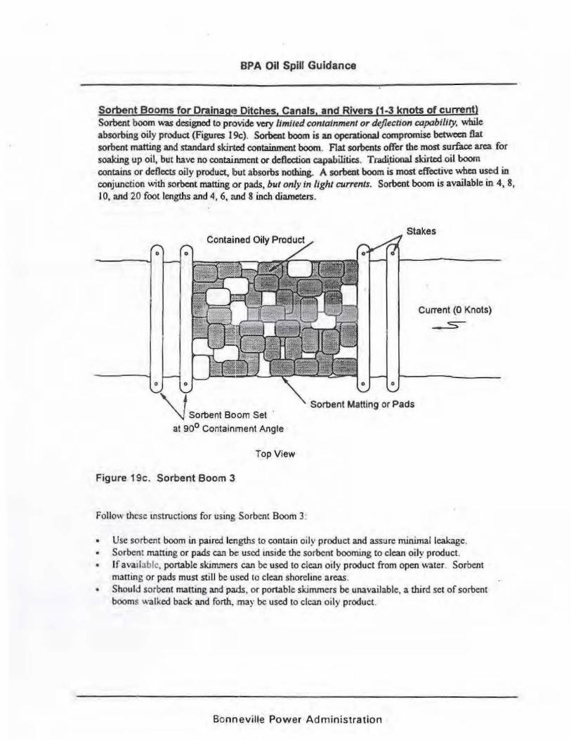
Figure 19c. Sorbent Boom 3
BPA Oil Spill Guidance
Sorbent Booms for Orainagt! Ditches, Canals, and Rivers (1·3 knots of current) Sorbent boom was designed to provide very limited containment or deflection capability, while absorbing oily product {Figures l9c). Sorbcnt boom is ao operationaJ compromise between flat sorbent matting and standard ski11ted containment boom . Flat sorbents offer the most surface area for soaking up oil, but have no containment or deflection capabilities. Tradi.tional skirted oil boom contains or deflects oily product, b ut absorbs nothing. A sorbent boom is most effective when used in conjunction with sorbent matting •:>r pads, but only in light currents. Sorbent boom is available in 4, 8, I 0, and 20 foot lengths and 4, 6, and 8 inch diameters .
Follow these IJlStructions for using Sorbent Boom 3:
• Use sorbent boom in pam!d lengths to contain oily product and assure minimal leakage . • So rbc nt matting or pads can be used inside the sorbcnt booming to clean oil y product. • If avatl3blc, portable sk.muners can be used to clean oily product from open wate r. Sorbent
mattin g or pads must still be used to clean shoreline areas . • Should sorbent matting and pads , or portable ski mmers be unavailable, a third set of sorbent
booms walked back and forth, may be used to clean oi ly produ ct.
Bonneville Power Administration

Contained Oily Product
Sorbent Boom Set Sorbent Matting or Pads
Stakes
Current (0 Knots)
~
at 90° Containment Angle
Top View
Figure 19d. Sorbent Boom 4
BPA Oil Spill Guidance
Sorbent Booms for Orafnag·e Ditches, Canals, and Rivers (1-3 knots of current) Sorbent boom was designed to provide very limited containment or deflection capability, while absorbing oily product (Figures 19d). Sorbent boom is an operational compromise between flat sorbent matting and standard slcirtod containment boom. Flat sorbents offer the most surface area for soaking up oil, but have no cootaiinment or deflection capabilities. Traditional skirted oil boqm contains or deflects oily product, but absorbs nothing. A sorbent boom is most effective when used in conjunction with sorbent matting or pads, but only in light currents. Sorbent boom is available in 4, 8, I 0, and 20 foot lengths and 4, 6, and 8 inch diameters. ·
Follow these instructions for using Sorbent Boom 4
• Use sorbent boom in paired lengths to contain otly product and assure minimal leakage. • Sorbent matting or pads can be used ins1de the sorbent booming to clean oily product.
- • If avai lable, portable skimmers can be used to clean oily product from open water. Sorbent matting or pads must still be used to clean shoreline a reas.
• Should sorbent matting and pads, or portable sk1mmers be unavatlable. a third set of sorbent booms walked back and forth.. may be used to clean oil~ product
Bonnf~vifle Power Admin istration

Stakes
Current (0 Knots) __s-
Sorbent Boom Set at 9r::P Containment Angle
Top View
Figure 19e. Sorbent Boom 5
BPA Oil Spill Guidance
Sorbent Booms for Drainagte Ditches, Canals, and Rivers (1-3 knots of current) Sorbeot boom was designed to pJTovide very limiled containment or·dejlection capability, while absorbing oily product (Figures l9e). Sorbent boom is an operational compromise between flat sorbent matting and standard skirted conta.inrneot boom. Flat sorbents offer the most surface area for soaking up oil, but have no containment or deflection capabilities. Traditional skirted oil boom contains or deflects oily product, butabsorbs nothing. A sorbeot boom is most effective when used· in conjunction with sorbent matting or pads, but only in light currents. Sorbent :OOOm is available in 4, 8, I 0, and 20 foot lengths and 4, 6, and 8 inch diameters .
• Use sorbent boom i.n paired lengths to co ntatn oily product and assure minimal leakage • Sorbent matting or pads can be used inside the so rbcnt booming to clean oily product. • Ifava ilab le, portable skimmers can be used to clean oily prod uct from open water. Sorbent
matting or pads must sttll be used to clean shoreline areas . • Shou ld sorbent matting and pads. or portab le sktmmers be una vailable, a thtrd set of sorbent
booms walked back and forth , ma y be used to clean oily produc t
Follow these instructions for using Sorbcnt Boom 5 :
Bonneville Power Administration