Appendix E Design and Costs for Measures - California
133
Appendix E Rough Designs and Cost Estimates for Water Temperature Measures
Transcript of Appendix E Design and Costs for Measures - California
Appendix E
Rough Designs and Cost Estimates for Water Temperature Measures

E-1
ROUGH DESIGNS AND COST ESTIMATES FOR WATER TEMPERATURE MEASURES
The purpose of this report is to describe the methods, assumptions, and resulting rough designs and cost estimates for measures to reduce water temperature along the NFFR. The measures covered include those comprising the initial Level 2 water temperature alternatives. These rough designs and cost estimates form the basis for the design layouts and cost estimates for the water temperature alternatives presented in Chapter 5 which were used to support Level 2 screening. They should be considered preliminary and subject to change based on further detailed analysis and design. They were prepared to a level rigor and detail deemed appropriate for project planning and for purposes of this Level 1 and 2 Report. The rough designs and cost estimates relied heavily on information provided by PG&E. This information included the following:
• Evaluation of Additional Alternative to Provide Cooler Water to the North Fork Feather River/ Pipe Yellow Creek Water Alternative (PG&E 2005c)
• Evaluation of Additional Alternative to Provide Cooler Water to the North Fork Feather River/ Mechanical Water Chillers Alternative (PG&E 2005d)
• Evaluation of Additional Alternative to Provide Cooler Water to the North Fork Feather River/ Mechanical Cooling Tower Alternative (PG&E 2005e)
• Prattville Intake Modifications Phase 3 Feasibility Study, Final Report (Black and Veatch 2004a)
• Prattville Intake Modifications Closeout Status Memorandum (Black and Veatch 2004b)
• North Fork Feather River Yellow Creek Diversion Cooling Water Pipeline Feasibility Study, Summary Report (Black and Veatch 2005a)
• Poe Tunnel Adit Feasibility Study/ Pre-Feasibility Level Sizing and Cost Estimate Summary Memorandum (Black and Veatch 2005b)
• Flow Improvement Modifications/ Plan & Sections/ Canyon Dam Intake Tower (Black and Veatch 2007)
• Miscellaneous design drawings of NFFR hydropower facilities provided by PG&E
DESIGN METHODOLOGY AND ASSUMPTIONS • Site Selection for Facilities and Conduit Alignments
Sites for facilities and conduit alignments were selected with the objective to simplify construction and minimize construction cost. USGS 7.5 minute topographical maps, aerial photos and other information provided by PG&E were examined during the site/alignment selection process. Sites for diversions and conduit alignments were selected to produce maximum head in order to reduce conduit size and construction costs.
E-2
• Conduit Materials
Conduit materials were as chosen based on the lowest cost material that would offer the best performance for a given application. In general, high density polyethylene (HDPE) was used for underwater conduit applications; black steel pipe (BSP) was used where flexibility was required due to site conditions with the potential for land movement; and reinforced concrete pipe (RCP) was used where site conditions would allow because of its low cost and long life.
• Diversion Structures
Inflatable rubber dams were used for stream diversions because their capability to deflate and allow for pass-through of flow, sediment, debris, and fish passage addressed concerns about establishing permanent instream barriers.
• Dredging
Dredging of the reservoir bottom using a dredging rig was required for excavating submerged channels and for preparing reservoir bottoms for setting and anchoring conduits. The dredging material was assumed to be soft, unconsolidated lake sediments. This assumption may need to be modified if Level 3 investigations reveal that the reservoirs along the NFFR have sediments mainly consisting of rocks that are markedly different.
• Modifications or Connections to Existing Hydropower Structures
Several modifications or connections to existing hydropower structure were included in various measures, as follows: - Three 13’ x 9.5’ reinforced concrete boxes were attached to the face of the Butt
Valley PH discharge outlet and carry flow 1,150 feet to the proposed regulating pond.
- A concrete regulating basin was attached to the face of Bucks Creek PH discharge to regulate the bypass flows and overflow into the North Fork Feather River.
- Gates #1 and #5 of the three low-level outlet gates at Canyon Dam Intake Tower were modified by connecting two pre-fabricated steel bulkheads with built-in slide gates to the existing outlets to enable controllable releases up to 600 cfs.
- Several submerged pipes were connected to existing outlets of dams. The feasibility of these modifications and connections will require further investigation.
• Thermal Curtains
The fixed U-shaped “long upper curtain” at Prattville Intake designed by Black and Veatch (2004a) was used as the main basis for the designs of the Caribou Intake and Belden PH Intake thermal curtains.

E-3
The fixed Γ-shaped upper curtain was selected for the Caribou Intake and Belden PH Intake thermal curtains to allow free flows to the spillways at Butt Valley Dam and Belden Dam.
• Water Chillers
The following criteria were used for selecting appropriate sites for chillers: 1) Close to upper end of the reach or near the dam; 2) Warm reservoir water could be conveyed to the chillers by gravity and the chilled
water could be returned by gravity back to the reach just below each dam; 3) Adequate open land space above the estimated flood plain; 4) No open land space along the Cresta reach was found to be available for
deployment of multiple chillers; therefore, a constructed deck was proposed. • Other Design Features
A submerged diffuser was proposed for all cold water plunging discharge outlets. The diffuser was designed to distribute the discharge in a larger cross sectional area for the purpose of reducing discharge velocity, turbulence and, hence, mixing.
ROUGH COST ESTIMATE METHODOLOGY AND ASSUMPTIONS Rough cost estimates considered capital cost, annual operation and maintenance (O&M) cost, and annual foregone power generation loss. Capital cost estimates were developed based on unit costs given in Means 2007, budgetary quotes from vendors, and cost derived from Black & Veatch estimates and Stetson databases. A 35% add-on for contingency/unlisted items and a 25% add-on for design and project management costs were used in the capital cost estimates. To allow for comparison of costs across water temperature alternatives, capital costs were amortized and converted to an equivalent annual cost based on an interest rate of 3% and useful lives that varied depending on the capital component. New facilities, such as thermal curtains1, diversion dams, bypass pipelines, constructed or modified low-level outlets, dredged channels, and water chillers, were assumed to have a useful life of 50 years. Annual O&M costs were estimated to be a percentage of capital costs. The breakdown of percentages is listed in the following table:
1 The Hypalon fabric used for thermal curtain applications, is a reinforced flexible geomembrane, a synthetic rubber product manufactured into plies that are combined over a reinforcing polyester scrim fabric. It has a demonstrated long life in harsh environments such as industrial wastes, sewage lagoons, and reservoir linings. It resists flexural cracking and abrasion as well as damaging effects of weather and heat.
E-4
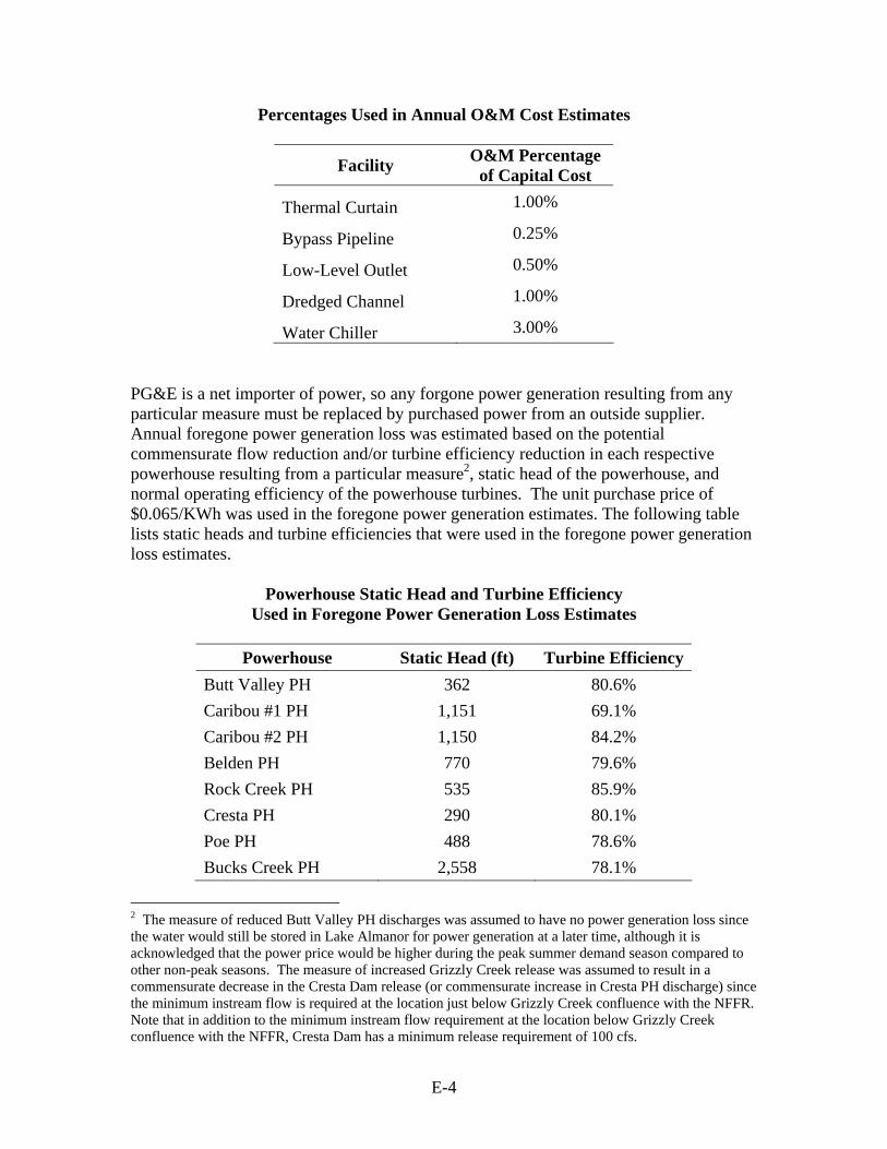
Percentages Used in Annual O&M Cost Estimates
Facility O&M Percentage of Capital Cost
Thermal Curtain 1.00%
Bypass Pipeline 0.25%
Low-Level Outlet 0.50%
Dredged Channel 1.00%
Water Chiller 3.00% PG&E is a net importer of power, so any forgone power generation resulting from any particular measure must be replaced by purchased power from an outside supplier. Annual foregone power generation loss was estimated based on the potential commensurate flow reduction and/or turbine efficiency reduction in each respective powerhouse resulting from a particular measure2, static head of the powerhouse, and normal operating efficiency of the powerhouse turbines. The unit purchase price of $0.065/KWh was used in the foregone power generation estimates. The following table lists static heads and turbine efficiencies that were used in the foregone power generation loss estimates.
Powerhouse Static Head and Turbine Efficiency
Used in Foregone Power Generation Loss Estimates
Powerhouse Static Head (ft) Turbine Efficiency Butt Valley PH 362 80.6% Caribou #1 PH 1,151 69.1% Caribou #2 PH 1,150 84.2% Belden PH 770 79.6% Rock Creek PH 535 85.9% Cresta PH 290 80.1% Poe PH 488 78.6% Bucks Creek PH 2,558 78.1%
2 The measure of reduced Butt Valley PH discharges was assumed to have no power generation loss since the water would still be stored in Lake Almanor for power generation at a later time, although it is acknowledged that the power price would be higher during the peak summer demand season compared to other non-peak seasons. The measure of increased Grizzly Creek release was assumed to result in a commensurate decrease in the Cresta Dam release (or commensurate increase in Cresta PH discharge) since the minimum instream flow is required at the location just below Grizzly Creek confluence with the NFFR. Note that in addition to the minimum instream flow requirement at the location below Grizzly Creek confluence with the NFFR, Cresta Dam has a minimum release requirement of 100 cfs.
E-5
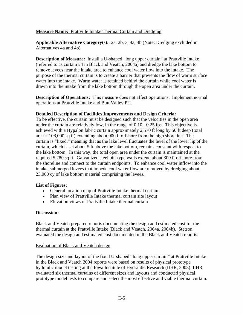
Measure Name: Prattville Intake Thermal Curtain and Dredging Applicable Alternative Category(s): 2a, 2b, 3, 4a, 4b (Note: Dredging excluded in Alternatives 4a and 4b) Description of Measure: Install a U-shaped “long upper curtain” at Prattville Intake (referred to as curtain #4 in Black and Veatch, 2004a) and dredge the lake bottom to remove levees near the intake area to enhance cool water flow into the intake. The purpose of the thermal curtain is to create a barrier that prevents the flow of warm surface water into the intake. Warm water is retained behind the curtain while cool water is drawn into the intake from the lake bottom through the open area under the curtain. Description of Operations: This measure does not affect operations. Implement normal operations at Prattville Intake and Butt Valley PH. Detailed Description of Facilities Improvements and Design Criteria: To be effective, the curtain must be designed such that the velocities in the open area under the curtain are relatively low, in the range of 0.10 - 0.25 fps. This objective is achieved with a Hypalon fabric curtain approximately 2,570 ft long by 50 ft deep (total area = 108,000 sq ft) extending about 900 ft offshore from the high shoreline. The curtain is “fixed,” meaning that as the lake level fluctuates the level of the lower lip of the curtain, which is set about 5 ft above the lake bottom, remains constant with respect to the lake bottom. In this way, the total open area under the curtain is maintained at the required 5,280 sq ft. Galvanized steel bin-type walls extend about 300 ft offshore from the shoreline and connect to the curtain endpoints. To enhance cool water inflow into the intake, submerged levees that impede cool water flow are removed by dredging about 23,000 cy of lake bottom material comprising the levees. List of Figures:
• General location map of Prattville Intake thermal curtain • Plan view of Prattville Intake thermal curtain site layout • Elevation views of Prattville Intake thermal curtain
Discussion: Black and Veatch prepared reports documenting the design and estimated cost for the thermal curtain at the Prattville Intake (Black and Veatch, 2004a, 2004b). Stetson evaluated the design and estimated cost documented in the Black and Veatch reports. Evaluation of Black and Veatch design The design size and layout of the fixed U-shaped “long upper curtain” at Prattville Intake in the Black and Veatch 2004 reports were based on results of physical prototype hydraulic model testing at the Iowa Institute of Hydraulic Research (IIHR, 2003). IIHR evaluated six thermal curtains of different sizes and layouts and conducted physical prototype model tests to compare and select the most effective and viable thermal curtain.

E-6
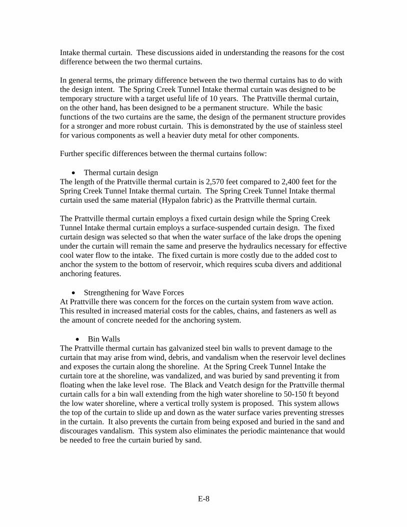
The most effective thermal curtain configuration was determined to be U-shaped, 900-feet x 770-feet x 900-feet (i.e., curtain #4). The most effective elevation of the curtain bottom was determined to be 4,455 ft (USGS datum). According to IIHR (2004), with the U-shaped long upper curtain in place and with the dredging of submerged levees at the Prattville Intake area, the Butt Valley PH discharge water temperature could be reduced by about 5.8°C and 5.2°C during July and August respectively at its normal operating discharge of 1,600 cfs. Dredging alone provides about 1.4°C and 1.6°C water temperature reduction at the Butt Valley PH during July and August respectively at its normal operating discharge of 1,600 cfs. IIHR also evaluated the effectiveness of installing a submerged hooded pipeline at the existing Prattville Intake to cause colder water to enter the intake. The thermal curtain measure was determined to be more effective. Stetson concludes that the basis of designing the fixed U-shaped “long upper curtain” at Prattville Intake for controlling the temperature of water entering the intake is technically-sound and acceptable. Evaluation of Black and Veatch cost estimate Initially, Black and Veatch estimated the cost of the “long upper curtain” (2,570 ft) and dredging at $8.3 million (2004a). After meeting with PG&E staff and discussing the report and design assumptions, Black and Veatch modified the design to strengthen the curtain against large wave forces and revised the estimated cost to about $17.8 million (2004b). The revision to the estimated cost was due to the modified design, changes in disposal site for the dredging material and other dredging-related costs, changes to costs for scuba diving for installation, prolonging of the construction schedule, and an increase in contingency from 25% to 35%. At first glance, the Black and Veatch estimated cost for the Prattville thermal curtain appears to differ markedly from the actual cost of a thermal curtain of similar length installed by the Bureau of Reclamation. This difference was investigated as a way of evaluating the reasonableness of the Black and Veatch cost estimate. In 1993, Reclamation installed thermal curtains at Whiskeytown and Lewiston Lakes in connection with the Whiskeytown Spring Creek Tunnel Intake and the Carr Powerplant tailrace. A report prepared by Tracy Vermeyen of Reclamation describing the nature of the work can be found at the following web address: http://www.usbr.gov/pmts/hydraulics_lab/tvermeyen/asce95m/index.html. The Spring Creek Tunnel Intake thermal curtain is a 100 ft deep, 2,400 ft long surface-suspended curtain which encloses the Spring Creek Tunnel intake. The curtain is surface-suspended, meaning that when the reservoir level drops the elevation of the bottom of the curtain also drops (see the following figure). In addition, the ends of curtain are anchored to shore so that when the water level drops the curtain gathers along the exposed reservoir shoreline. Installation took 4 months to complete at a cost of $1.8 million in contractor labor and materials.

E-7
Plan and Elevation Views of Reclamation’s Thermal Curtain at Spring Creek
Tunnel Intake (Source: Bureau of Reclamation 1997) Mr. Greg O’Haver, former Reclamation employee in charge of construction of the Whiskeytown thermal curtain project, and Ms. Tracy Vermeyen, Reclamation project engineer for the hydraulic study, were contacted to discuss the Spring Creek Tunnel
E-8
Intake thermal curtain. These discussions aided in understanding the reasons for the cost difference between the two thermal curtains. In general terms, the primary difference between the two thermal curtains has to do with the design intent. The Spring Creek Tunnel Intake thermal curtain was designed to be temporary structure with a target useful life of 10 years. The Prattville thermal curtain, on the other hand, has been designed to be a permanent structure. While the basic functions of the two curtains are the same, the design of the permanent structure provides for a stronger and more robust curtain. This is demonstrated by the use of stainless steel for various components as well a heavier duty metal for other components. Further specific differences between the thermal curtains follow:
• Thermal curtain design The length of the Prattville thermal curtain is 2,570 feet compared to 2,400 feet for the Spring Creek Tunnel Intake thermal curtain. The Spring Creek Tunnel Intake thermal curtain used the same material (Hypalon fabric) as the Prattville thermal curtain. The Prattville thermal curtain employs a fixed curtain design while the Spring Creek Tunnel Intake thermal curtain employs a surface-suspended curtain design. The fixed curtain design was selected so that when the water surface of the lake drops the opening under the curtain will remain the same and preserve the hydraulics necessary for effective cool water flow to the intake. The fixed curtain is more costly due to the added cost to anchor the system to the bottom of reservoir, which requires scuba divers and additional anchoring features.
• Strengthening for Wave Forces At Prattville there was concern for the forces on the curtain system from wave action. This resulted in increased material costs for the cables, chains, and fasteners as well as the amount of concrete needed for the anchoring system.
• Bin Walls
The Prattville thermal curtain has galvanized steel bin walls to prevent damage to the curtain that may arise from wind, debris, and vandalism when the reservoir level declines and exposes the curtain along the shoreline. At the Spring Creek Tunnel Intake the curtain tore at the shoreline, was vandalized, and was buried by sand preventing it from floating when the lake level rose. The Black and Veatch design for the Prattville thermal curtain calls for a bin wall extending from the high water shoreline to 50-150 ft beyond the low water shoreline, where a vertical trolly system is proposed. This system allows the top of the curtain to slide up and down as the water surface varies preventing stresses in the curtain. It also prevents the curtain from being exposed and buried in the sand and discourages vandalism. This system also eliminates the periodic maintenance that would be needed to free the curtain buried by sand.

E-9
• Dredging The Prattville thermal curtain design calls for dredging of submerged levees on the lake bottom near the intake, which was not included in the Spring Creek Tunnel Intake thermal curtain. The hydraulic study prepared by the Iowa Institute of Hydraulic Research (IIHR, 2003) based on a physical prototype hydraulic model and referenced in the Black and Vetch report (2004a) found that the levees must be removed in order to allow cool water to be drawn to the intake.
• Scuba Diving The cost for divers to install various components of the Prattville thermal curtain is anticipated to be substantially higher than the cost incurred at the Spring Creek Tunnel Intake thermal curtain. This higher cost is due to the added complexity of the fixed curtain’s anchoring system.
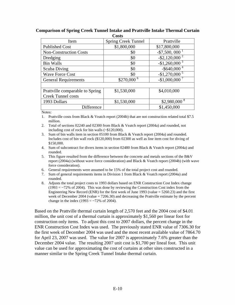
• Concrete At Prattville additional concrete is needed to anchor the curtain. The cost of concrete world-wide has increased substantially since 1993 when the Spring Creek Tunnel Intake thermal curtain was installed. The revised Black and Veatch report (2004b) placed the total capital construction, design, and other pre-construction costs of the Prattville thermal curtain at approximately $17.8 million. In order to compare the costs of Prattville and Spring Creek Tunnel Intake thermal curtains certain itemized costs for components that were not included in the Spring Creek Tunnel Intake thermal curtain construction cost were deducted from the Prattville total cost. The costs included dredging, bin walls, and other cost items. The remaining common Prattville thermal curtain costs were adjusted to 1993 dollars to be comparable to the Spring Creek Tunnel Intake thermal curtain costs. This comparative cost analysis is summarized in the following table. The General Requirements section (mobilization, supervision, temporary facilities and utilities, safety, and miscellaneous) for the Prattville thermal curtain accounts for slightly more than $1 million, far less than it likely accounted for on the Spring Creek Tunnel Intake thermal curtain. The primary factor driving this cost for Prattville is the overall cost since this figure is estimated based on the scale of the project and the overall total project cost. While the comparable costs in 1993 dollars are different they are of similar magnitude. It appears that the Prattville thermal curtain is more costly due to increased complexity and numerous other factors that differentiate it from the Spring Creek Tunnel Intake thermal curtain. Absent detailed examination of the Black and Veatch design and cost (2004a, 2004b), the Prattville thermal curtain and cost estimate, while conservative, appears to be reasonable and acceptable for use in this Level 2 analysis.
E-10
Comparison of Spring Creek Tunnel Intake and Prattville Intake Thermal Curtain Costs
Item Spring Creek Tunnel Prattville Published Cost $1,800,000 $17,800,000 Non-Construction Costs $0 -$7,500, 000 1 Dredging $0 -$2,120,000 2 Bin Walls $0 -$1,260,000 3 Scuba Diving $0 -$640,000 4 Wave Force Cost $0 -$1,270,000 5 General Requirements $270,000 6 -$1,000,000 7 Prattville comparable to Spring Creek Tunnel costs
$1,530,000 $4,010,000
1993 Dollars $1,530,000 $2,980,000 8 Difference $1,450,000
Notes: 1. Prattville costs from Black & Veatch report (2004b) that are not construction related total $7.5
million. 2. Total of sections 02240 and 02300 from Black & Veatch report (2004a) and rounded, not
including cost of rock for bin walls (~$120,000). 3. Sum of bin walls item in section 05100 from Black & Veatch report (2004a) and rounded.
Includes cost of bin wall rock ($120,000) from 02300 as well as line item cost for diving of $150,000.
4. Sum of subcontract for divers items in section 02480 from Black & Veatch report (2004a) and rounded.
5. This figure resulted from the difference between the concrete and metals sections of the B&V report (2004a) (without wave force consideration) and Black & Veatch report (2004b) (with wave force consideration).
6. General requirements were assumed to be 15% of the total project cost and rounded. 7. Sum of general requirements items in Division 1 from Black & Veatch report (2004a) and
rounded. 8. Adjusts the total project costs to 1993 dollars based on ENR Construction Cost Index change
(1993 = ~72% of 2004). This was done by reviewing the Construction Cost index from the Engineering New Record (ENR) for the first week of June 1993 (value = 5260.23) and the first week of December 2004 (value = 7206.30) and decreasing the Prattville estimate by the percent change in the index (1993 = ~72% of 2004).
Based on the Prattville thermal curtain length of 2,570 feet and the 2004 cost of $4.01 million, the unit cost of a thermal curtain is approximately $1,560 per linear foot for construction only items. To adjust this cost to 2007 dollars, the percent change in the ENR Construction Cost Index was used. The previously stated ENR value of 7306.30 for the first week of December 2004 was used and the most recent available value of 7864.70 for April 23, 2007 was used. The value for 2007 is approximately 7.6% greater than the December 2004 value. The resulting 2007 unit cost is $1,700 per lineal foot. This unit value can be used for approximating the cost of curtains at other sites constructed in a manner similar to the Spring Creek Tunnel Intake thermal curtain.
E-11
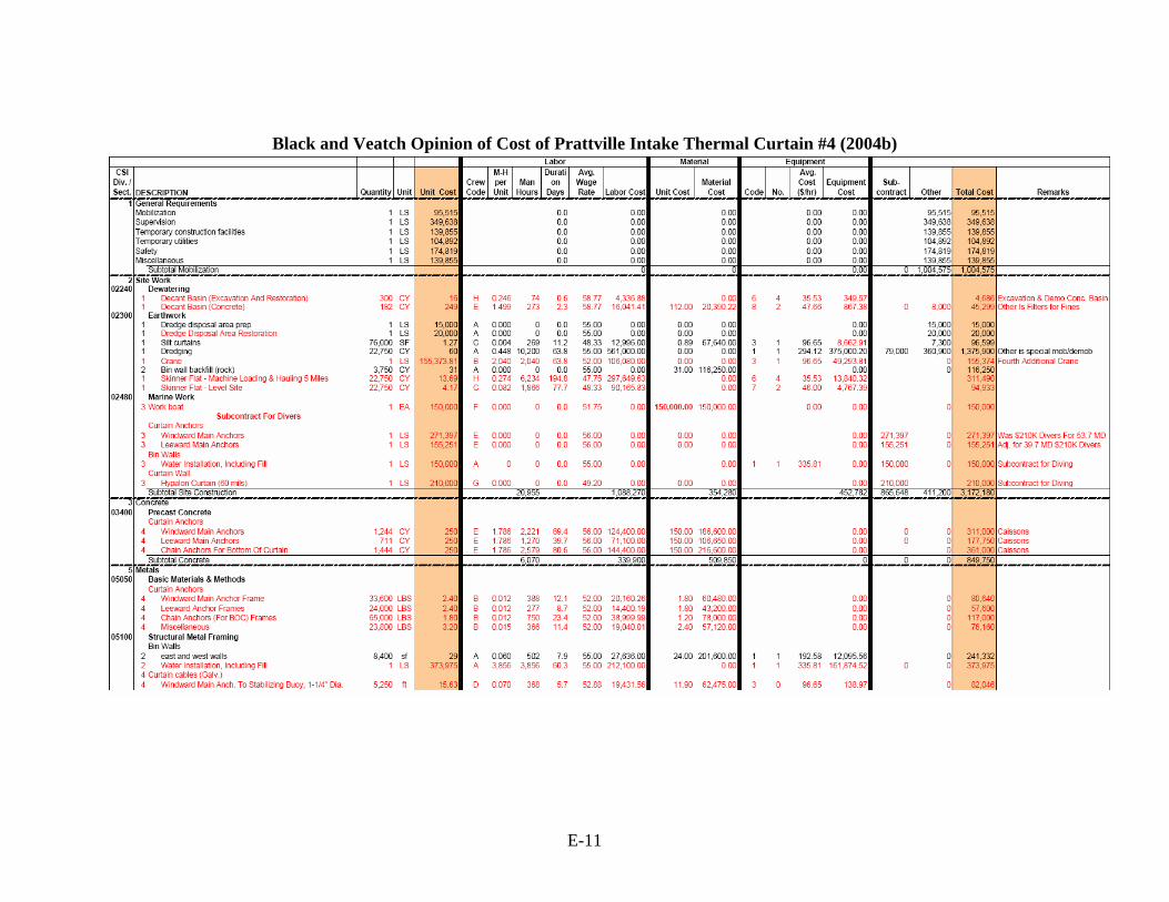
Black and Veatch Opinion of Cost of Prattville Intake Thermal Curtain #4 (2004b)
E-12
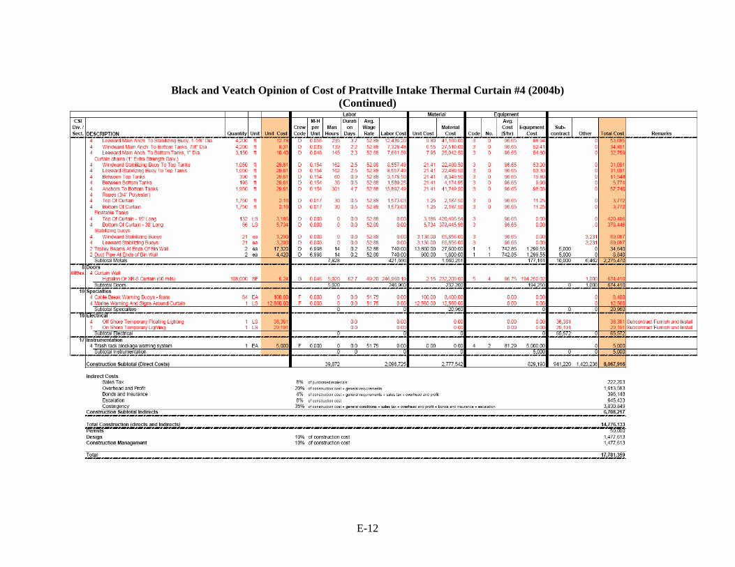
Black and Veatch Opinion of Cost of Prattville Intake Thermal Curtain #4 (2004b) (Continued)

Lake
Almanor
Causeway
Valley
Butt
Reservoir
B e n n e r C r e e k B e n n e r C r e e k
Chester Flood C
ontrol Channel
N o r t h F
o r k F e a t h e r R i v e r
H a m
i l t o n B r a n c h
H a m
i l t o n B r a n c h
Canyon Dam
Canyon Dam
Bail ey Cre
ek
Bail ey Cre
ek
PRATTVILLE
Prattville Intake Thermal Curtain
0 2,500 5,000
Feet
A13
36
147
89
Butt Valley PH
HamiltonBranch PHHamiltonBranch PH
General Location Map ofPrattville IntakeThermal Curtain
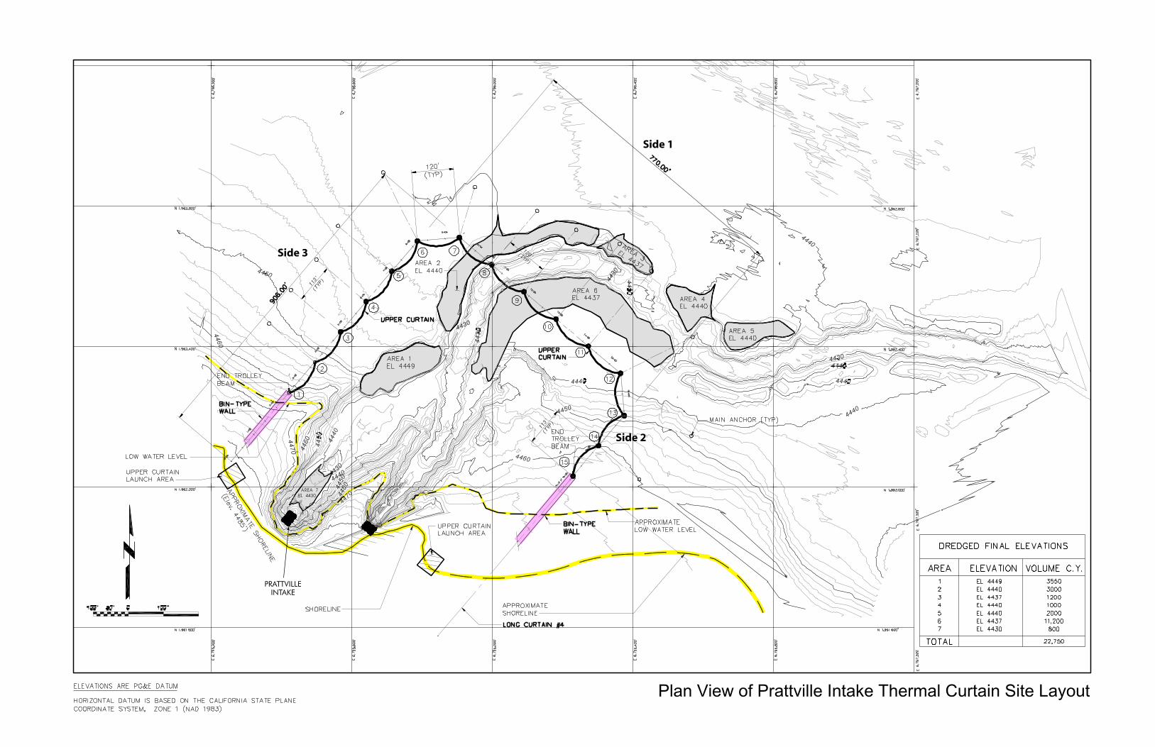
AREA 7EL 4430
Side 1
Side 2
Side 3
Plan View of Prattville Intake Thermal Curtain Site Layout
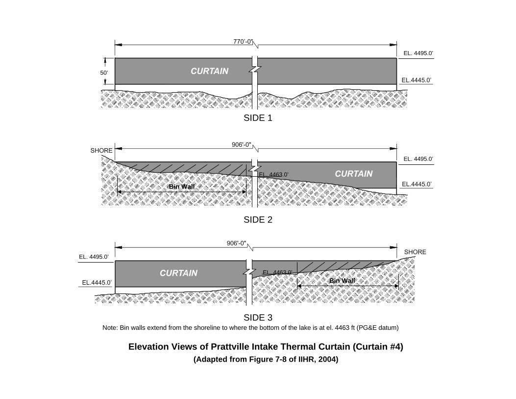
SIDE 1
SIDE 2
SIDE 3
EL. 4463.0’
EL. 4463.0’Bin Wall
Bin Wall
Note: Bin walls extend from the shoreline to where the bottom of the lake is at el. 4463 ft (PG&E datum)
Elevation Views of Prattville Intake Thermal Curtain (Curtain #4)(Adapted from Figure 7-8 of IIHR, 2004)
EL. 4495.0’
EL. 4495.0’
EL. 4495.0’
50’

E-13
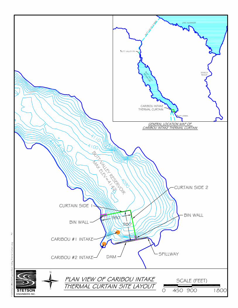
Measure Name: Caribou Intake Thermal Curtain Applicable Alternative Category(s): 2b, 3, 4a Description of Measure: Install a fixed Γ-shaped “long upper curtain” near the Caribou Intakes. The purpose of the thermal curtain is to create a barrier that prevents the flow of warm surface water into the intake. Warm water is retained behind the curtain while cool water is drawn from the lake bottom into the intake through the open area under the curtain. The Γ-shaped curtain does not affect flow to the spillway at Butt Valley Dam. Description of Operations: This measure does not affect operations. Implement normal operations at Caribou Intakes and Caribou PHs. Detailed Description of Facilities Improvements and Design Criteria: To be effective, the curtain must be designed such that the velocities in the open area under the curtain are relatively low, in the range of 0.10 - 0.25 fps. This objective is achieved with a Hypalon fabric curtain approximately 1,960 ft long by 42 ft deep (total area = 63,000 sq ft) extending about 980 ft offshore from the high shoreline. The curtain is “fixed,” meaning that as the reservoir level fluctuates the level of the lower lip of the curtain, which is set about 10 ft above the reservoir bottom, remains constant with respect to the reservoir bottom. In this way, the total open area under the curtain is maintained at the required 5,930 sq ft. Galvanized steel bin-type walls extend about 200 ft offshore from the shoreline and connect to the curtain endpoints. List of Figures:
• General location map of Caribou Intake thermal curtain • Plan view of Caribou Intake thermal curtain site layout • Elevation views of Caribou Intake thermal curtain
Key Design or Construction Uncertainties Requiring Further Study:
• The Caribou Intake thermal curtain design is conceptual, particularly the curtain location and curtain depth. Further analysis is needed to develop details for the design and operation of the curtain, including physical prototype hydraulic testing and/or mathematical hydrodynamic modeling.
Discussion: Butt Valley Reservoir has a storage capacity of 49,897 acre-feet. Water surface elevations fluctuate by about 10 to 15 feet from the maximum water surface elevation of 4,142 feet (USGS datum) on an annual basis. The reservoir serves as the afterbay to Butt Valley PH and the forebay for the Caribou No.1 and No. 2 PHs. Some additional flow enters Butt Valley Reservoir through Butt Creek and possibly through seepage. Water is delivered to the two Caribou powerhouses through two separate intake structures near Butt Valley Dam and there are no low-level outlets constructed at the dam. The Caribou No. 1 Intake is located at an invert elevation of 4,077 feet (USGS datum) in Butt Valley Reservoir and delivers up to 1,100 cfs to the Caribou #1 PH. The Caribou No. 2 Intake is located in a shallow cove area with an entrance elevation of 4,110 feet (USGS datum)
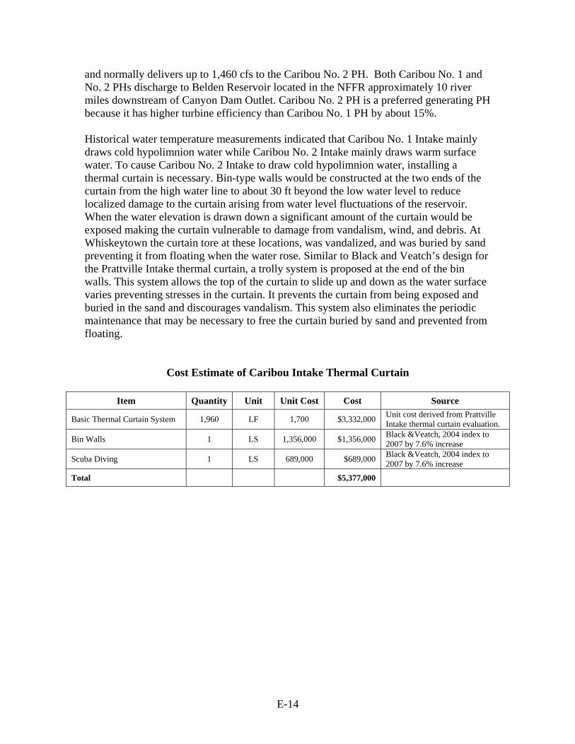
E-14
and normally delivers up to 1,460 cfs to the Caribou No. 2 PH. Both Caribou No. 1 and No. 2 PHs discharge to Belden Reservoir located in the NFFR approximately 10 river miles downstream of Canyon Dam Outlet. Caribou No. 2 PH is a preferred generating PH because it has higher turbine efficiency than Caribou No. 1 PH by about 15%. Historical water temperature measurements indicated that Caribou No. 1 Intake mainly draws cold hypolimnion water while Caribou No. 2 Intake mainly draws warm surface water. To cause Caribou No. 2 Intake to draw cold hypolimnion water, installing a thermal curtain is necessary. Bin-type walls would be constructed at the two ends of the curtain from the high water line to about 30 ft beyond the low water level to reduce localized damage to the curtain arising from water level fluctuations of the reservoir. When the water elevation is drawn down a significant amount of the curtain would be exposed making the curtain vulnerable to damage from vandalism, wind, and debris. At Whiskeytown the curtain tore at these locations, was vandalized, and was buried by sand preventing it from floating when the water rose. Similar to Black and Veatch’s design for the Prattville Intake thermal curtain, a trolly system is proposed at the end of the bin walls. This system allows the top of the curtain to slide up and down as the water surface varies preventing stresses in the curtain. It prevents the curtain from being exposed and buried in the sand and discourages vandalism. This system also eliminates the periodic maintenance that may be necessary to free the curtain buried by sand and prevented from floating.
Cost Estimate of Caribou Intake Thermal Curtain
Item Quantity Unit Unit Cost Cost Source
Basic Thermal Curtain System 1,960 LF 1,700 $3,332,000 Unit cost derived from Prattville Intake thermal curtain evaluation.
Bin Walls 1 LS 1,356,000 $1,356,000 Black &Veatch, 2004 index to 2007 by 7.6% increase
Scuba Diving 1 LS 689,000 $689,000 Black &Veatch, 2004 index to 2007 by 7.6% increase
Total $5,377,000


E-15
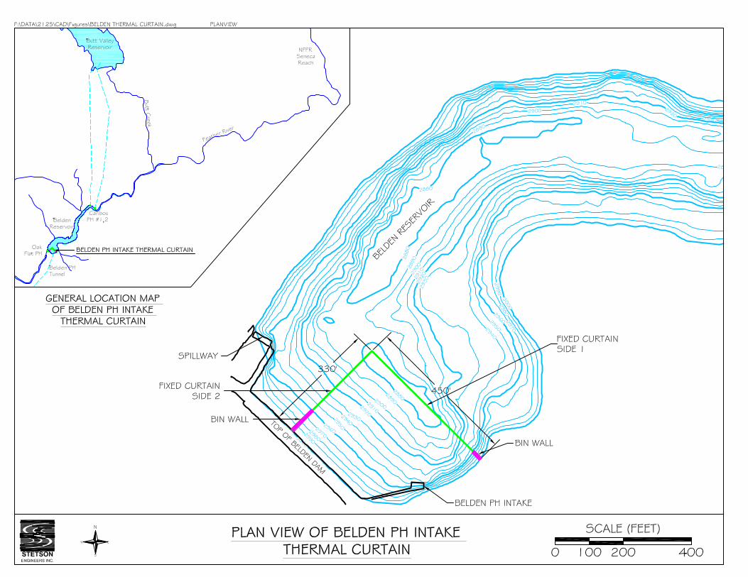
Measure Name: Belden PH Intake Thermal Curtain Applicable Alternative Category(s): 5; additional measure for Belden Reach Description of Measure: Install a fixed Γ-shaped “upper curtain” at the Belden PH Intake. The purpose of the thermal curtain is to allow the Belden PH Intake to draw cool water from the lower strata of Belden Reservoir to Belden PH for the purpose of reducing water temperatures in the downstream Rock Creek, Cresta, and Poe reaches, while maintaining sufficient cold water release to the Belden Reach from the low-level outlet of Belden Dam. The Γ-shaped curtain does not affect flow to the spillway at Belden Dam. Description of Operations: This measure does not affect operations. Implement normal operations at Belden PH Intake and Belden PH. Detailed Description of Facilities Improvements and Design Criteria: To be effective, the curtain must be designed such that the velocities in the open area under the curtain are relatively low, in the range of 0.10 - 0.25 fps. This objective is achieved with a Hypalon fabric curtain approximately 780 ft long by 55 ft deep (total area = 36,710 sq ft) extending about 400 ft offshore from the high shoreline. The curtain is “fixed,” meaning that as the reservoir level fluctuates the level of the lower lip of the curtain, which is set about 50 ft above the reservoir bottom, remains constant with respect to the reservoir bottom. In this way, the total open area under the curtain is maintained at the required 23,040 sq ft. Galvanized steel bin-type walls extend about 35-80 ft offshore from the shoreline and connect to the curtain endpoints. List of Figures:
• General location map of Belden PH Intake thermal curtain • Plan view of Belden PH Intake thermal curtain site layout • Elevation views of Belden PH Intake thermal curtain
Key Design or Construction Uncertainties Requiring Further Study:
• The Belden PH Intake thermal curtain design is conceptual, particularly the curtain location and curtain depth. Further analysis is required to develop details for the design and operation of the curtain. In particular further analysis to evaluate the sustainability of routing cold water through the reservoir by balancing inflows relative to outflows will be required. Belden Reservoir outflows include (1) the instream flow released to the NFFR below Belden Dam, and (2) the power generation flow drawn through the Belden intake structure for delivery to Belden PH. The ability to sustain a thermally stratified condition created by the cold water plunging and routing through Belden Reservoir will be evaluated using modeling techniques.
Discussion: Belden Reservoir has a maximum water surface elevation of 2,985 feet (USGS datum) and a theoretical usable storage capacity of 2,477 acre-feet. Under normal operations, the water surface elevation fluctuates between 2,960 and 2,973 feet, depending on power
E-16
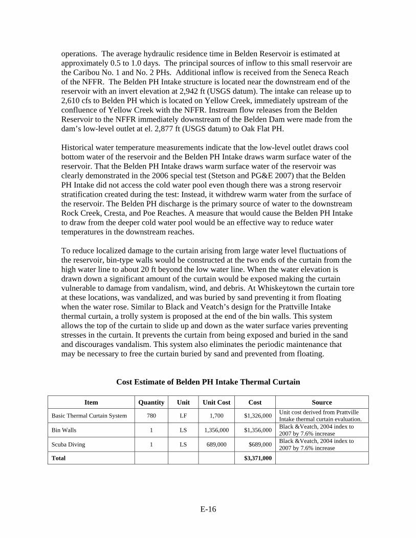
operations. The average hydraulic residence time in Belden Reservoir is estimated at approximately 0.5 to 1.0 days. The principal sources of inflow to this small reservoir are the Caribou No. 1 and No. 2 PHs. Additional inflow is received from the Seneca Reach of the NFFR. The Belden PH Intake structure is located near the downstream end of the reservoir with an invert elevation at 2,942 ft (USGS datum). The intake can release up to 2,610 cfs to Belden PH which is located on Yellow Creek, immediately upstream of the confluence of Yellow Creek with the NFFR. Instream flow releases from the Belden Reservoir to the NFFR immediately downstream of the Belden Dam were made from the dam’s low-level outlet at el. 2,877 ft (USGS datum) to Oak Flat PH. Historical water temperature measurements indicate that the low-level outlet draws cool bottom water of the reservoir and the Belden PH Intake draws warm surface water of the reservoir. That the Belden PH Intake draws warm surface water of the reservoir was clearly demonstrated in the 2006 special test (Stetson and PG&E 2007) that the Belden PH Intake did not access the cold water pool even though there was a strong reservoir stratification created during the test: Instead, it withdrew warm water from the surface of the reservoir. The Belden PH discharge is the primary source of water to the downstream Rock Creek, Cresta, and Poe Reaches. A measure that would cause the Belden PH Intake to draw from the deeper cold water pool would be an effective way to reduce water temperatures in the downstream reaches. To reduce localized damage to the curtain arising from large water level fluctuations of the reservoir, bin-type walls would be constructed at the two ends of the curtain from the high water line to about 20 ft beyond the low water line. When the water elevation is drawn down a significant amount of the curtain would be exposed making the curtain vulnerable to damage from vandalism, wind, and debris. At Whiskeytown the curtain tore at these locations, was vandalized, and was buried by sand preventing it from floating when the water rose. Similar to Black and Veatch’s design for the Prattville Intake thermal curtain, a trolly system is proposed at the end of the bin walls. This system allows the top of the curtain to slide up and down as the water surface varies preventing stresses in the curtain. It prevents the curtain from being exposed and buried in the sand and discourages vandalism. This system also eliminates the periodic maintenance that may be necessary to free the curtain buried by sand and prevented from floating.
Cost Estimate of Belden PH Intake Thermal Curtain
Item Quantity Unit Unit Cost Cost Source
Basic Thermal Curtain System 780 LF 1,700 $1,326,000 Unit cost derived from Prattville Intake thermal curtain evaluation.
Bin Walls 1 LS 1,356,000 $1,356,000 Black &Veatch, 2004 index to 2007 by 7.6% increase
Scuba Diving 1 LS 689,000 $689,000 Black &Veatch, 2004 index to 2007 by 7.6% increase
Total $3,371,000


E-17
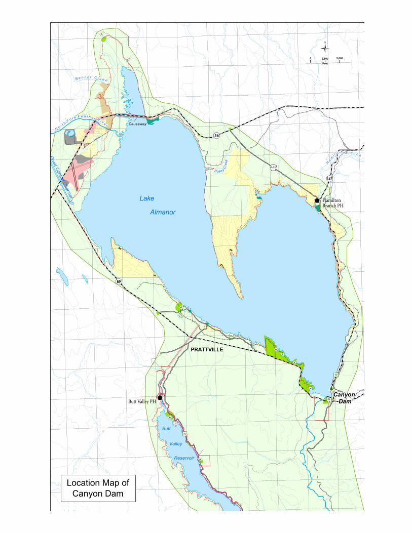
Measure Name: Modify/Repair Canyon Dam Low-Level Outlet and Increase Release Applicable Alternative Category(s): 2c, 3, 4c, 5a, 5b, 5c, 6a Description of Measure: Modify/repair the Canyon Dam low-level outlet and increase cool water release from the low-level outlet as needed during the summer. At present, the low-level outlet can safely release up to only 73 cfs. The purpose of this measure is to increase the cool water release from the hypolimnion of Lake Almanor to the NFFR. Description of Operations: Depending upon the alternative, the release rate of the Canyon Dam low-level outlet ranges from about 90 cfs to 600 cfs. The maximum allowable discharge to avoid potential adverse impacts arising from velocity and scour to aquatic habitat along the Seneca Reach is estimated at about 700 cfs 3. Increasing Canyon Dam release would require decreasing Prattville Intake release commensurately to avoid lake level fluctuation or changes from the operating rules agreed to in the Partial Settlement Agreement. High release from the Canyon Dam low-level outlet would cause hydropower generation loss. The feasibility of hydropower generation to recover the foregone power by constructing a powerhouse below Canyon Dam will be investigated further in Level 3. Detailed Description of Facilities Improvements and Design Criteria: Modify and repair two (Gates #1 and #5) of the three low level outlets by connecting two pre-fabricated steel bulkheads with built-in slide gates to the existing outlets to enable controllable releases up to 600 cfs. Modifying and repairing Gate #1 only can release up to about 340 cfs. List of Figures:
• Location map of Canyon Dam • Flow Improvement Modifications/ Plan & Sections/ Canyon Dam Intake Tower
Key Design or Construction Uncertainties Requiring Further Study:
• There are concerns about vibrations during high discharges which require further study.
3 At 700 cfs, the river stage is approximately at bankfull in the lower half of the Seneca reach near the Seneca Resort and China Bar areas. Flows exceeding about 700 cfs result in over bank flows in this reach (PG&E 2002), which would, therefore, be avoided. Flows between 600 and 700 cfs begin to mobilize spawning gravel and flows greater than 700 cfs can result in significant movement of streambed materials in the Seneca reach (PG&E 2002). Since most trout spawning and egg incubation is completed by July (PG&E 2002), any minor movement of gravel at flows as high as 700 cfs would not disturb fish nests. Habitat area for adult trout increases with flow to near a maximum between 300 and 800 cfs, but it gradually decreases for rearing juvenile trout from a maximum habitat area at about 50 cfs to about 70% of the maximum at 700 cfs (PG&E 2002). However, juvenile trout rearing habitat provided at a flow of 700 cfs would result in about 80% of that provided by the FERC-recommended minimum stream flows during the same season (13,000 ft2/1000 ft vs. 16,000 ft2/1000 ft) (PG&E 2002). Although some variable decrease in juvenile rearing habitat area could occur during periods when river temperature management would be needed, it is not likely to limit trout production (Source: Keith. Marine, Fisheries Scientist, NSR, June 8, 2007). This estimate of the maximum allowable discharge will be re-examined in Level 3.

E-18
• The design used the normal maximum water surface elevation of Lake Almanor as the basis for providing up to 600 cfs flows when all low-level gates and valves are opened. Actual flows through each gate or valve needs to be determined using field data and shop testing prior to installation.
• The required number of gages and valves depend on the required release rate from the low-level outlet which will be studied further in Level 3.
Discussion: The Canyon Dam Intake Tower has three low level outlets gates – Gates #1, #3, #5 – all are set at elevation 4432 ft, about 72 ft below the maximum lake level elevation of 4504 ft USGS datum4. These three low level gates are damaged or are in poor condition due to corrosion and long-term hydrostatic loading on the gates and gate-stems. PG&E inspections revealed the bad gate-stems, gate connections, and bolts. In August-October 2005 did repair work on Gate #5 and rehabilitated the gate and gate-stem connection at a cost of about $860,000. Gate #5 is the only low level gate that is currently operable, but its operation is limited and it can reliably and safely release up to only about 73 cfs. The needed modification and repair work to Gates #1 and #5 is depicted in preliminary design drawings prepared by Black and Veatch. PG&E estimates the cost to complete the work at about $10 million per gate, for a total cost for both gates of about $20 million. This estimate is based in large part on actual costs incurred in the repair of Gate #5. To comply with FERC requirements, PG&E is currently investigating the need for additional modifications and repairs to the overall Canyon Dam Outlet Tower and Tunnel Works to address concerns about vibrations during high discharges and outlet capacity limitations. It may be possible to incorporate the modification and repair work to Gates #1 and #5 described herein into this overall workplan.
4 There are two additional gates that are set even lower, Gates #2 and #4, at el. 4410. But these two gates are buried under about 20 ft of sediment and are considered unrepairable and permanently inoperable.
Lake
Almanor
Causeway
Valley
Butt
Reservoir
B e n n e r C r e e k B e n n e r C r e e k
Chester Flood C
ontrol Channel
N o r t h F
o r k F e a t h e r R i v e r
H a m
i l t o n B r a n c h
H a m
i l t o n B r a n c h
Canyon Dam
Canyon Dam
Bail ey Cre
ek
Bail ey Cre
ek
PRATTVILLE
0 2,500 5,000
Feet
A13
36
147
89
Butt Valley PH
HamiltonBranch PHHamiltonBranch PH
Location Map ofCanyon Dam

Intentionally Not Shown: Figure of Flow Improvement Modifications/Plan and Sections/Canyon Dam Intake
Tower
E-19
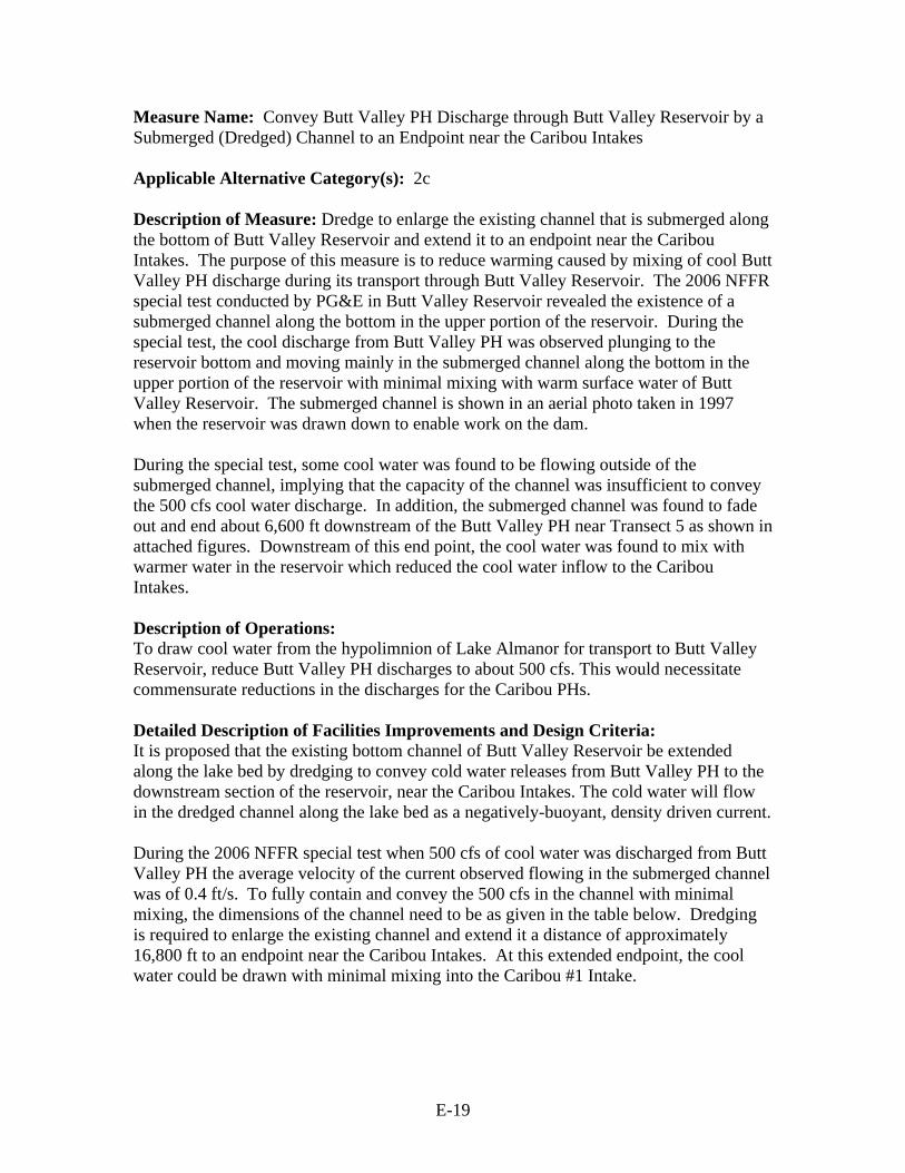
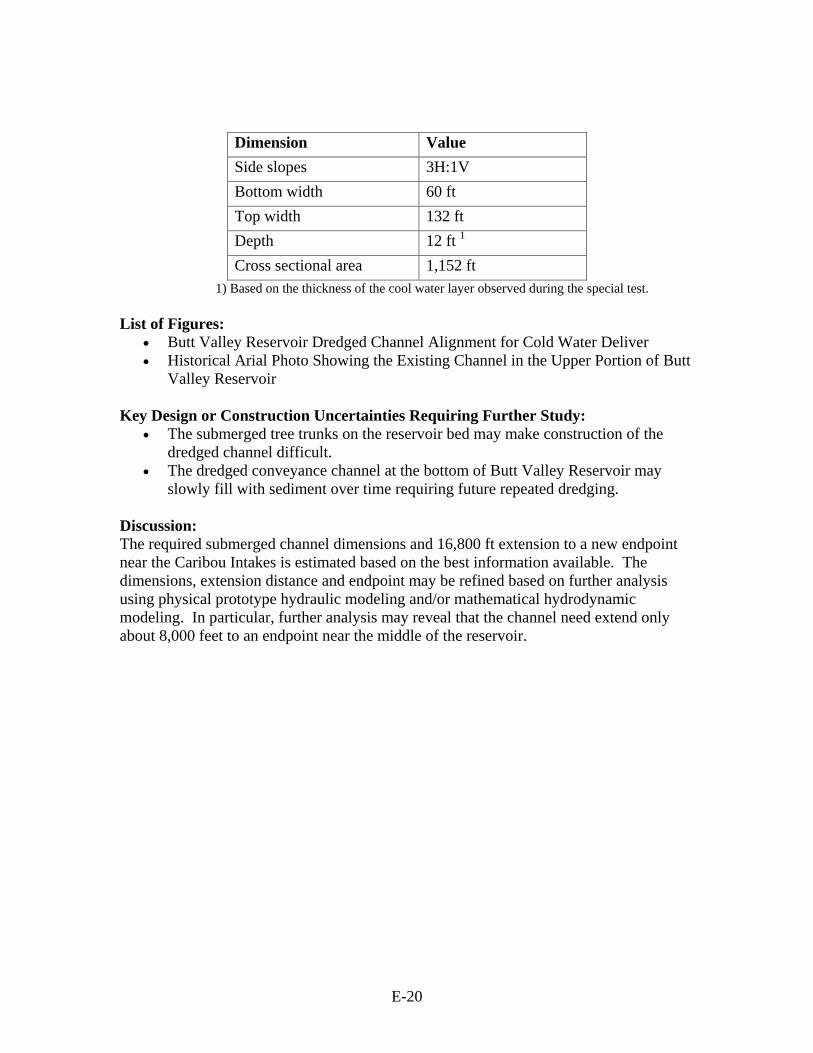
Measure Name: Convey Butt Valley PH Discharge through Butt Valley Reservoir by a Submerged (Dredged) Channel to an Endpoint near the Caribou Intakes Applicable Alternative Category(s): 2c Description of Measure: Dredge to enlarge the existing channel that is submerged along the bottom of Butt Valley Reservoir and extend it to an endpoint near the Caribou Intakes. The purpose of this measure is to reduce warming caused by mixing of cool Butt Valley PH discharge during its transport through Butt Valley Reservoir. The 2006 NFFR special test conducted by PG&E in Butt Valley Reservoir revealed the existence of a submerged channel along the bottom in the upper portion of the reservoir. During the special test, the cool discharge from Butt Valley PH was observed plunging to the reservoir bottom and moving mainly in the submerged channel along the bottom in the upper portion of the reservoir with minimal mixing with warm surface water of Butt Valley Reservoir. The submerged channel is shown in an aerial photo taken in 1997 when the reservoir was drawn down to enable work on the dam. During the special test, some cool water was found to be flowing outside of the submerged channel, implying that the capacity of the channel was insufficient to convey the 500 cfs cool water discharge. In addition, the submerged channel was found to fade out and end about 6,600 ft downstream of the Butt Valley PH near Transect 5 as shown in attached figures. Downstream of this end point, the cool water was found to mix with warmer water in the reservoir which reduced the cool water inflow to the Caribou Intakes. Description of Operations: To draw cool water from the hypolimnion of Lake Almanor for transport to Butt Valley Reservoir, reduce Butt Valley PH discharges to about 500 cfs. This would necessitate commensurate reductions in the discharges for the Caribou PHs. Detailed Description of Facilities Improvements and Design Criteria: It is proposed that the existing bottom channel of Butt Valley Reservoir be extended along the lake bed by dredging to convey cold water releases from Butt Valley PH to the downstream section of the reservoir, near the Caribou Intakes. The cold water will flow in the dredged channel along the lake bed as a negatively-buoyant, density driven current. During the 2006 NFFR special test when 500 cfs of cool water was discharged from Butt Valley PH the average velocity of the current observed flowing in the submerged channel was of 0.4 ft/s. To fully contain and convey the 500 cfs in the channel with minimal mixing, the dimensions of the channel need to be as given in the table below. Dredging is required to enlarge the existing channel and extend it a distance of approximately 16,800 ft to an endpoint near the Caribou Intakes. At this extended endpoint, the cool water could be drawn with minimal mixing into the Caribou #1 Intake.
E-20
Dimension Value Side slopes 3H:1V Bottom width 60 ft Top width 132 ft Depth 12 ft 1 Cross sectional area 1,152 ft
1) Based on the thickness of the cool water layer observed during the special test. List of Figures:
• Butt Valley Reservoir Dredged Channel Alignment for Cold Water Deliver • Historical Arial Photo Showing the Existing Channel in the Upper Portion of Butt
Valley Reservoir Key Design or Construction Uncertainties Requiring Further Study:
• The submerged tree trunks on the reservoir bed may make construction of the dredged channel difficult.
• The dredged conveyance channel at the bottom of Butt Valley Reservoir may slowly fill with sediment over time requiring future repeated dredging.
Discussion: The required submerged channel dimensions and 16,800 ft extension to a new endpoint near the Caribou Intakes is estimated based on the best information available. The dimensions, extension distance and endpoint may be refined based on further analysis using physical prototype hydraulic modeling and/or mathematical hydrodynamic modeling. In particular, further analysis may reveal that the channel need extend only about 8,000 feet to an endpoint near the middle of the reservoir.
E-21
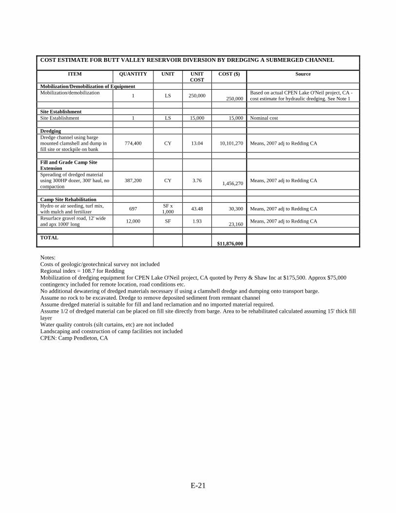
COST ESTIMATE FOR BUTT VALLEY RESERVOIR DIVERSION BY DREDGING A SUBMERGED CHANNEL
ITEM QUANTITY UNIT UNIT
COST COST ($) Source
Mobilization/Demobilization of Equipment Mobilization/demobilization 1 LS 250,000
250,000 Based on actual CPEN Lake O'Neil project, CA - cost estimate for hydraulic dredging. See Note 1
Site Establishment Site Establishment 1 LS 15,000 15,000 Nominal cost Dredging Dredge channel using barge mounted clamshell and dump in fill site or stockpile on bank
774,400 CY 13.04 10,101,270 Means, 2007 adj to Redding CA
Fill and Grade Camp Site Extension
Spreading of dredged material using 300HP dozer, 300' haul, no compaction
387,200 CY 3.76 1,456,270 Means, 2007 adj to Redding CA
Camp Site Rehabilitation Hydro or air seeding, turf mix, with mulch and fertilizer 697 SF x
1,000 43.48 30,300 Means, 2007 adj to Redding CA
Resurface gravel road, 12' wide and apx 1000' long 12,000 SF 1.93
23,160 Means, 2007 adj to Redding CA
TOTAL
$11,876,000
Notes: Costs of geologic/geotechnical survey not included Regional index = 108.7 for Redding Mobilization of dredging equipment for CPEN Lake O'Neil project, CA quoted by Perry & Shaw Inc at $175,500. Approx $75,000 contingency included for remote location, road conditions etc. No additional dewatering of dredged materials necessary if using a clamshell dredge and dumping onto transport barge. Assume no rock to be excavated. Dredge to remove deposited sediment from remnant channel Assume dredged material is suitable for fill and land reclamation and no imported material required. Assume 1/2 of dredged material can be placed on fill site directly from barge. Area to be rehabilitated calculated assuming 15' thick fill layer Water quality controls (silt curtains, etc) are not included Landscaping and construction of camp facilities not included CPEN: Camp Pendleton, CA

Butt Valley ReservoirTypical Transect Profiles
Transect 3
0
5
10
15
20
25
0 200 400 600 800 1000 1200 1400 1600
Length (ft, from left bank looking downstream)
Dep
th (f
t)
Existing Remnant Channel
Finished Dredged Channel Profile3:1 Side Slopes

Transect 4
Transect 5 is farther downstream of this photo boundary
Historical Arial Photo showing the Existing Channel in the Upper Portion of Butt Valley Reservoir
E-22
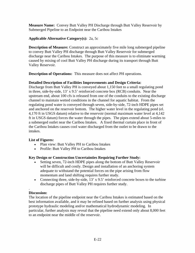
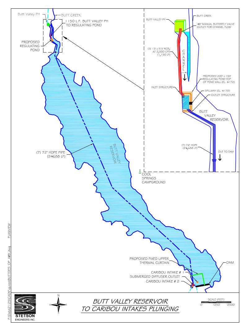
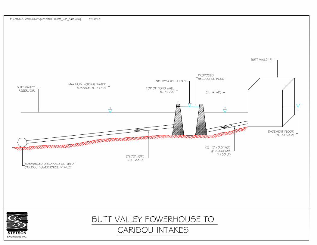
Measure Name: Convey Butt Valley PH Discharge through Butt Valley Reservoir by Submerged Pipeline to an Endpoint near the Caribou Intakes Applicable Alternative Category(s): 2a, 5c Description of Measure: Construct an approximately five mile long submerged pipeline to convey Butt Valley PH discharge through Butt Valley Reservoir for submerged discharge near the Caribou Intakes. The purpose of this measure is to eliminate warming caused by mixing of cool Butt Valley PH discharge during its transport through Butt Valley Reservoir. Description of Operations: This measure does not affect PH operations. Detailed Description of Facilities Improvements and Design Criteria: Discharge from Butt Valley PH is conveyed about 1,150 feet to a small regulating pond in three, side-by-side, 13’ x 9.5’ reinforced concrete box (RCB) conduits. Near the upstream end, about 100 cfs is released from one of the conduits to the existing discharge channel to maintain wetted conditions in the channel for aquatic habitat. From the regulating pond water is conveyed through seven, side-by-side, 72-inch HDPE pipes set and anchored on the reservoir bottom. The higher water level in the regulating pond (el. 4,170 ft in USGS datum) relative to the reservoir (normal maximum water level at 4,142 ft in USGS datum) forces the water through the pipes. The pipes extend about 5-miles to a submerged outlet near the Caribou Intakes. A fixed thermal curtain place in front of the Caribou Intakes causes cool water discharged from the outlet to be drawn to the intakes. List of Figures:
• Plan view: Butt Valley PH to Caribou Intakes • Profile: Butt Valley PH to Caribou Intakes
Key Design or Construction Uncertainties Requiring Further Study:
• Setting seven, 72-inch HDPE pipes along the bottom of Butt Valley Reservoir will be difficult and costly. Design and installation of an anchoring system adequate to withstand the potential forces on the pipe arising from flow momentum and land shifting requires further study.
• Connecting three, side-by-side, 13’ x 9.5’ reinforced concrete boxes to the turbine discharge pipes of Butt Valley PH requires further study.
. Discussion: The location of the pipeline endpoint near the Caribou Intakes is estimated based on the best information available, and it may be refined based on further analysis using physical prototype hydraulic modeling and/or mathematical hydrodynamic modeling. In particular, further analysis may reveal that the pipeline need extend only about 8,000 feet to an endpoint near the middle of the reservoir.

E-23
COST ESTIMATE FOR BUTT VALLEY PH TO CARIBOU INTAKES 2,000 CFS
ITEM QUANITY UNIT UNIT COST COST
Bypass Conduit from Butt Valley PH
to Proposed Detention Basin Triple, 13' x 9.5' Reinforced Concrete
Box 1150 LF 2,115 2,432,250
Tie in Structure at Powerhouse 1 LS 15,000 $15,000 48-inch hydraulic operated butterfly valve
for in channel low flow 1 LS 47,000 $47,000 Excavation, truck mounted, 6-10' deep, 1
CY excavator, Hydraulic Jack hammer 9583 CY 12 $114,996 Backfill, 6" layers, roller compaction
operator walking 23000 CY 44 $1,006,940 Compaction, walk behind vibrating plate,
18" wide, 6" lifts, 4 passes 23000 CY 3 $69,690 Grouted Riprap Slope Protection, 3/8 to
1/4 CY Pieces, 18" Thick 7283 SY 120 $877,165 1/2 CY bucket wheel mounted front end
loader, min haul 32583 CY 16 $517,744 Hauling, 20 mile round trip, 0.4 loads/ hr
(Added 15% for Expansion) 15430 CY 27 $410,438 Sediment and Erosion Control (Silt
Fence) 1150 LF 5 $5,819
Sub total $5,497,000
Detention Basin Compaction, walk behind vibrating plate,
18" wide, 6" lifts, 4 passes 46602 CY 3 $141,204 Backfill, 6" layers, roller compaction
operator walking 46602 CY 44 $2,040,236
Concrete bottom for detention basin 550 CY 1,800 $990,000 1/2 CY bucket wheel mounted front end
loader, min haul 53592 CY 16 $851,577 Hauling, 20 mile round trip, 0.4 loads/ hr
(Add 15% for Expansion) 53592 CY 27 $1,425,547
Outlet Structure 1 LS 50,000 $50,000
Inlet Structure 1 LS 100,000 $100,000
Hydroseeding 3600 SY 1 $3,600 Sediment and Erosion Control (Silt
Fence) 500 LF 5 $2,530
Sub total $5,605,000
(7) 72" HDPE from Proposed Detention Basin to Plunging
72-inch HDPE (Length Mult by 7) 172816 LF 425 $73,446,800 HDPE Pipe Placement, concrete weight
collars / "Float Flood" method, Mechanical Crane, barge mounted 1 LS 4,400,000 $4,400,000
Underwater pipe laying preparation of reservoir bottom 1 LS 9,077,000 $9,077,000
Diffuser Outlet Structure 1 LS 50,000 $50,000 Attach 72" HDPE to diffuser structure
and install pad / rock cover 1 LS 150,000 $150,000
Upper Thermal Curtain around both 1 LS 3,101,500 $3,101,500

E-24
Caribou Intakes
Sub total $90,225,000
Mobilization
Dozer, above 150 HP (3) 1 LS 3,600 $3,600
Excavator, 1-1.5 CY Diesel Hyd. (2) 1 LS 9,600 $9,600
Loader (2) 1 LS 2,400 $2,400
Dump truck, 26 tons (10) 1 LS 6,000 $6,000
25 ton truck mounted hydraulic crane (2) 1 LS 2,000 $2,000
Crawler Type Drill, 4" (1) 1 LS 700 $700
Grout pumper (1) 1 LS 600 $600
Water truck, 6000 gal (1) 1 LS 600 $600
Wash & Screen (1) 1 LS 7,200 $7,200 Mechanical Dredger / Crane, barge mounted and all loading equipment 1 LS 200,000 $200,000
Sub total Mob /
Demob $233,000
$101,560,000
E-25
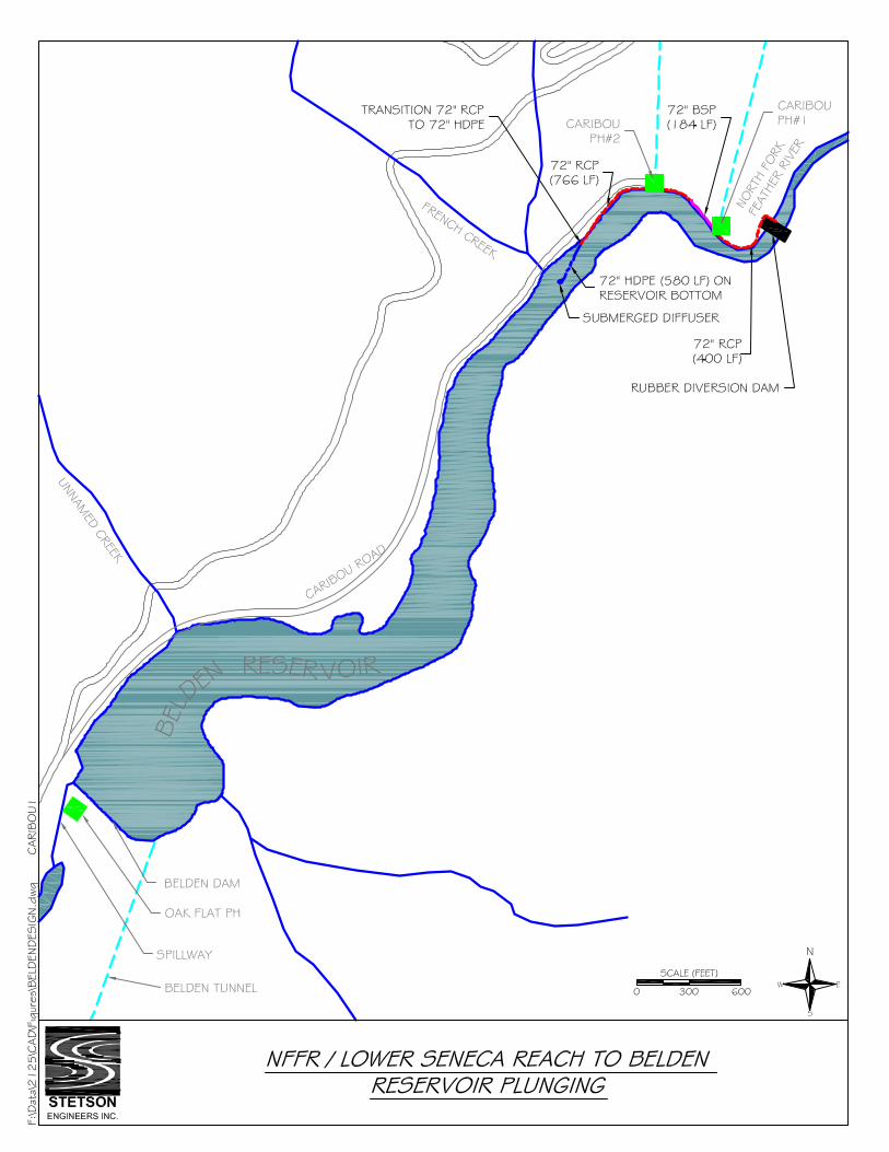
Measure Name: Divert Cool Seneca Reach Flows into a Submerged Pipeline to Discharge at an Appropriate Plunging Point in Belden Reservoir Applicable Alternative Category(s): 5, 6; additional measure for Belden Reach Description of Measure: Construct an approximately 1,900 ft long pipeline to convey cool Seneca Reach flows directly to a plunging location in Belden Reservoir, bypassing discharges from Caribou PHs No. 1 and 2. The purpose of this measure is to avoid mixing cool Seneca flows with warmer discharges from the Caribou PHs during operational hours and minimize mixing with warmer ambient waters near the surface of Belden Reservoir. Field observations in Belden Reservoir during the 2006 NFFR special test and preliminary reservoir hydrodynamic modeling by Stetson identified a plunging location downstream of which further mixing during transport along the bottom of the reservoir is minimal. Description of Operations: This measure has no affect on PH operations. Operate the diversion system to convey about 250 cfs through the pipeline and spill the remaining flow over the dam. The diversion rate is supplied by the increased release measure from Canyon Dam low-level outlet. The flow accretion along the Seneca Reach, including inflows from lower Butt Creek, would maintain flows for aquatic habitat in the stream over the short distance between the diversion dam and the Caribou No. 1 discharge. Detailed Description of Facilities Improvements and Design Criteria: Construct a 7-foot high inflatable/deflatable rubber diversion dam at the lower end of Seneca Reach just upstream of Caribou PH No. 1. Except during summer, the rubber dam would remain in the deflated position. Construct an approximately 1,900 ft long pipeline to convey cool Seneca Reach flows captured behind the dam to a plunging location in Belden Reservoir. The pipeline starts at the diversion dam and extends about 1,900 ft to a submerged diffuser at the bottom of Belden Reservoir. The first segment of the pipeline is about 400 feet long and consists of 72-inch reinforced concrete pipe (RCP) trenched into the river bank and covered with riprap. The second segment is about 180 feet long and consists of 72-inch Black Steel Pipe (BSP) which is connected to the face of Caribou PH #1, delivering flows to the northwest bank of the NFFR just upstream of Caribou PH #2. The third segment is about 360 ft long and consists of 72-inch RCP which is trenched along the toe of the north bank of the NFFR and protected with riprap. The fourth segment is about 400 feet and consists of 72-inch RCP which is buried along the shoulder of Caribou Road. The fifth and last segment is about 580 feet long and consists of 72-inch HPDE pipe that enters Belden Reservoir and is set on and anchored to the bottom of the reservoir for the remaining 580 feet. A submerged diffuser outlet is placed at the end of the pipeline to distribute the discharge in a larger cross sectional area for the purpose of reducing discharge velocity, turbulence, and mixing potential.

E-26
List of Figures: • Plan view: NFFR / Lower Seneca Reach to Belden Reservoir Plunging. • Profile: NFFR / Lower Seneca Reach to Belden Reservoir Plunging Outlet.
Key Design or Construction Uncertainties Requiring Further Study:
• Setting a 72-inch HDPE along the bottom of Belden Reservoir will be difficult and costly. Design and installation of an anchoring system adequate to withstand the potential forces on the pipe arising from flow momentum and land shifting requires further study.
• Placing and connecting a 72-inch reinforced concrete or black steel pipe to the faces of both powerhouses will require blasting and difficult construction, which could be hazardous due to unstable slopes and recent landslides.
• Pipeline construction beside Caribou Road will require blasting, jack hammering work due to the existing conditions being steep rock cliffs near the powerhouses, which could be hazardous due to unstable slopes and recent landslides.
Discussion: The design and cost estimate for this measure is based on a flow rate of 250 cfs. The flow rate may be refined based on further analysis using mathematical hydrodynamic modeling which could affect the design.
E-27
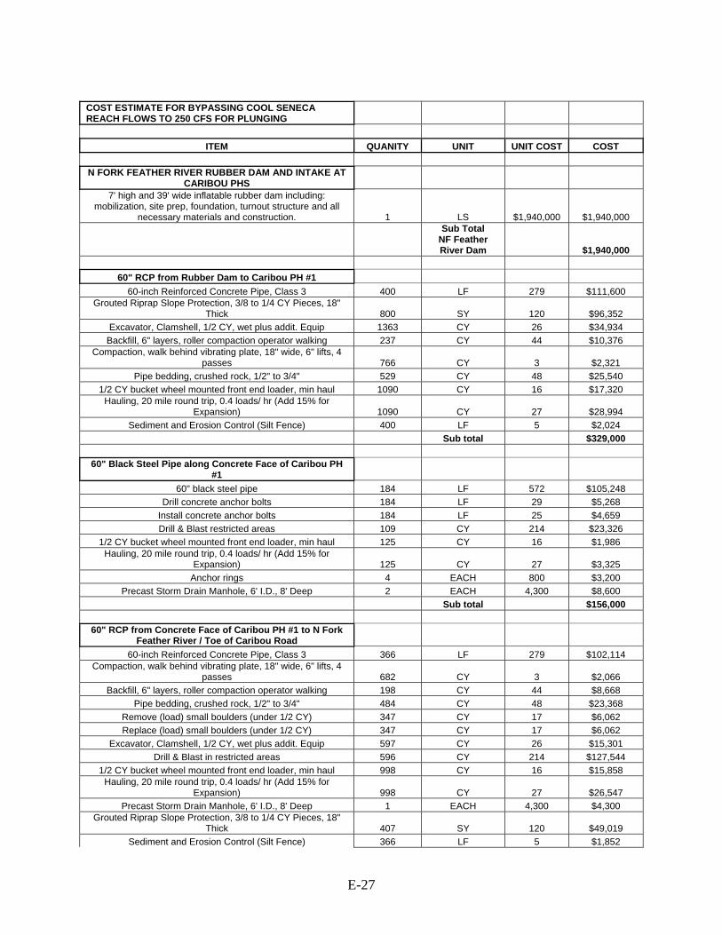
COST ESTIMATE FOR BYPASSING COOL SENECA REACH FLOWS TO 250 CFS FOR PLUNGING
ITEM QUANITY UNIT UNIT COST COST
N FORK FEATHER RIVER RUBBER DAM AND INTAKE AT CARIBOU PHS
7' high and 39' wide inflatable rubber dam including: mobilization, site prep, foundation, turnout structure and all
necessary materials and construction. 1 LS $1,940,000 $1,940,000
Sub Total NF Feather River Dam $1,940,000
60" RCP from Rubber Dam to Caribou PH #1
60-inch Reinforced Concrete Pipe, Class 3 400 LF 279 $111,600 Grouted Riprap Slope Protection, 3/8 to 1/4 CY Pieces, 18"
Thick 800 SY 120 $96,352 Excavator, Clamshell, 1/2 CY, wet plus addit. Equip 1363 CY 26 $34,934
Backfill, 6" layers, roller compaction operator walking 237 CY 44 $10,376 Compaction, walk behind vibrating plate, 18" wide, 6" lifts, 4
passes 766 CY 3 $2,321 Pipe bedding, crushed rock, 1/2" to 3/4" 529 CY 48 $25,540
1/2 CY bucket wheel mounted front end loader, min haul 1090 CY 16 $17,320 Hauling, 20 mile round trip, 0.4 loads/ hr (Add 15% for
Expansion) 1090 CY 27 $28,994 Sediment and Erosion Control (Silt Fence) 400 LF 5 $2,024
Sub total $329,000
60" Black Steel Pipe along Concrete Face of Caribou PH #1
60" black steel pipe 184 LF 572 $105,248 Drill concrete anchor bolts 184 LF 29 $5,268
Install concrete anchor bolts 184 LF 25 $4,659 Drill & Blast restricted areas 109 CY 214 $23,326
1/2 CY bucket wheel mounted front end loader, min haul 125 CY 16 $1,986 Hauling, 20 mile round trip, 0.4 loads/ hr (Add 15% for
Expansion) 125 CY 27 $3,325 Anchor rings 4 EACH 800 $3,200
Precast Storm Drain Manhole, 6' I.D., 8' Deep 2 EACH 4,300 $8,600 Sub total $156,000
60" RCP from Concrete Face of Caribou PH #1 to N Fork Feather River / Toe of Caribou Road
60-inch Reinforced Concrete Pipe, Class 3 366 LF 279 $102,114 Compaction, walk behind vibrating plate, 18" wide, 6" lifts, 4
passes 682 CY 3 $2,066 Backfill, 6" layers, roller compaction operator walking 198 CY 44 $8,668
Pipe bedding, crushed rock, 1/2" to 3/4" 484 CY 48 $23,368 Remove (load) small boulders (under 1/2 CY) 347 CY 17 $6,062 Replace (load) small boulders (under 1/2 CY) 347 CY 17 $6,062
Excavator, Clamshell, 1/2 CY, wet plus addit. Equip 597 CY 26 $15,301 Drill & Blast in restricted areas 596 CY 214 $127,544
1/2 CY bucket wheel mounted front end loader, min haul 998 CY 16 $15,858 Hauling, 20 mile round trip, 0.4 loads/ hr (Add 15% for
Expansion) 998 CY 27 $26,547 Precast Storm Drain Manhole, 6' I.D., 8' Deep 1 EACH 4,300 $4,300
Grouted Riprap Slope Protection, 3/8 to 1/4 CY Pieces, 18" Thick 407 SY 120 $49,019
Sediment and Erosion Control (Silt Fence) 366 LF 5 $1,852
E-28
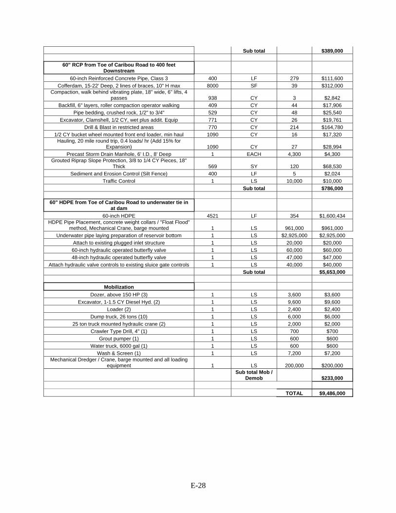
Sub total $389,000
60" RCP from Toe of Caribou Road to 400 feet Downstream
60-inch Reinforced Concrete Pipe, Class 3 400 LF 279 $111,600 Cofferdam, 15-22' Deep, 2 lines of braces, 10" H max 8000 SF 39 $312,000
Compaction, walk behind vibrating plate, 18" wide, 6" lifts, 4 passes 938 CY 3 $2,842
Backfill, 6" layers, roller compaction operator walking 409 CY 44 $17,906 Pipe bedding, crushed rock, 1/2" to 3/4" 529 CY 48 $25,540
Excavator, Clamshell, 1/2 CY, wet plus addit. Equip 771 CY 26 $19,761 Drill & Blast in restricted areas 770 CY 214 $164,780
1/2 CY bucket wheel mounted front end loader, min haul 1090 CY 16 $17,320 Hauling, 20 mile round trip, 0.4 loads/ hr (Add 15% for
Expansion) 1090 CY 27 $28,994 Precast Storm Drain Manhole, 6' I.D., 8' Deep 1 EACH 4,300 $4,300
Grouted Riprap Slope Protection, 3/8 to 1/4 CY Pieces, 18" Thick 569 SY 120 $68,530
Sediment and Erosion Control (Silt Fence) 400 LF 5 $2,024 Traffic Control 1 LS 10,000 $10,000
Sub total $786,000
60" HDPE from Toe of Caribou Road to underwater tie in at dam
60-inch HDPE 4521 LF 354 $1,600,434 HDPE Pipe Placement, concrete weight collars / "Float Flood"
method, Mechanical Crane, barge mounted 1 LS 961,000 $961,000 Underwater pipe laying preparation of reservoir bottom 1 LS $2,925,000 $2,925,000
Attach to existing plugged inlet structure 1 LS 20,000 $20,000 60-inch hydraulic operated butterfly valve 1 LS 60,000 $60,000 48-inch hydraulic operated butterfly valve 1 LS 47,000 $47,000
Attach hydraulic valve controls to existing sluice gate controls 1 LS 40,000 $40,000 Sub total $5,653,000
Mobilization Dozer, above 150 HP (3) 1 LS 3,600 $3,600
Excavator, 1-1.5 CY Diesel Hyd. (2) 1 LS 9,600 $9,600 Loader (2) 1 LS 2,400 $2,400
Dump truck, 26 tons (10) 1 LS 6,000 $6,000 25 ton truck mounted hydraulic crane (2) 1 LS 2,000 $2,000
Crawler Type Drill, 4" (1) 1 LS 700 $700 Grout pumper (1) 1 LS 600 $600
Water truck, 6000 gal (1) 1 LS 600 $600 Wash & Screen (1) 1 LS 7,200 $7,200
Mechanical Dredger / Crane, barge mounted and all loading equipment 1 LS 200,000 $200,000
Sub total Mob /
Demob $233,000 TOTAL $9,486,000
E-29
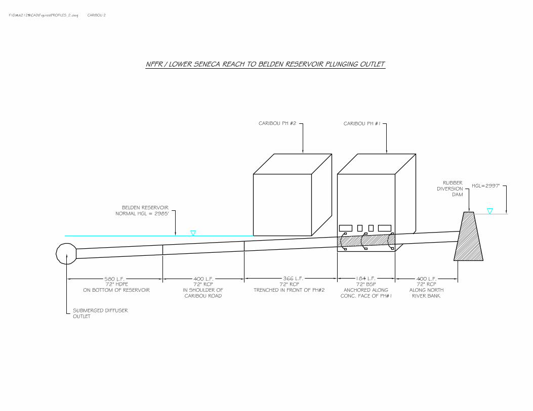
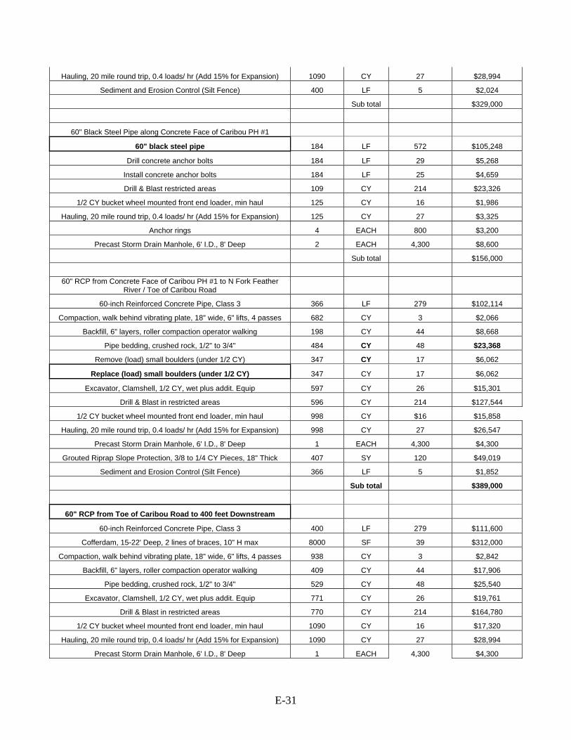
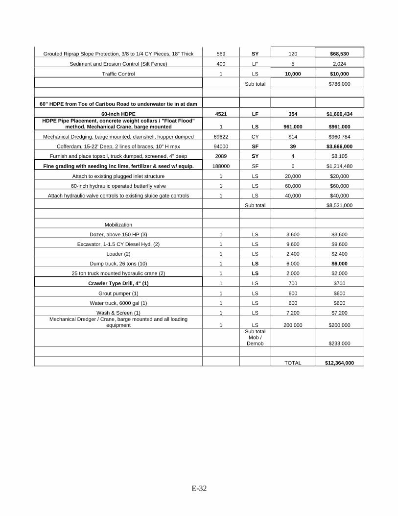
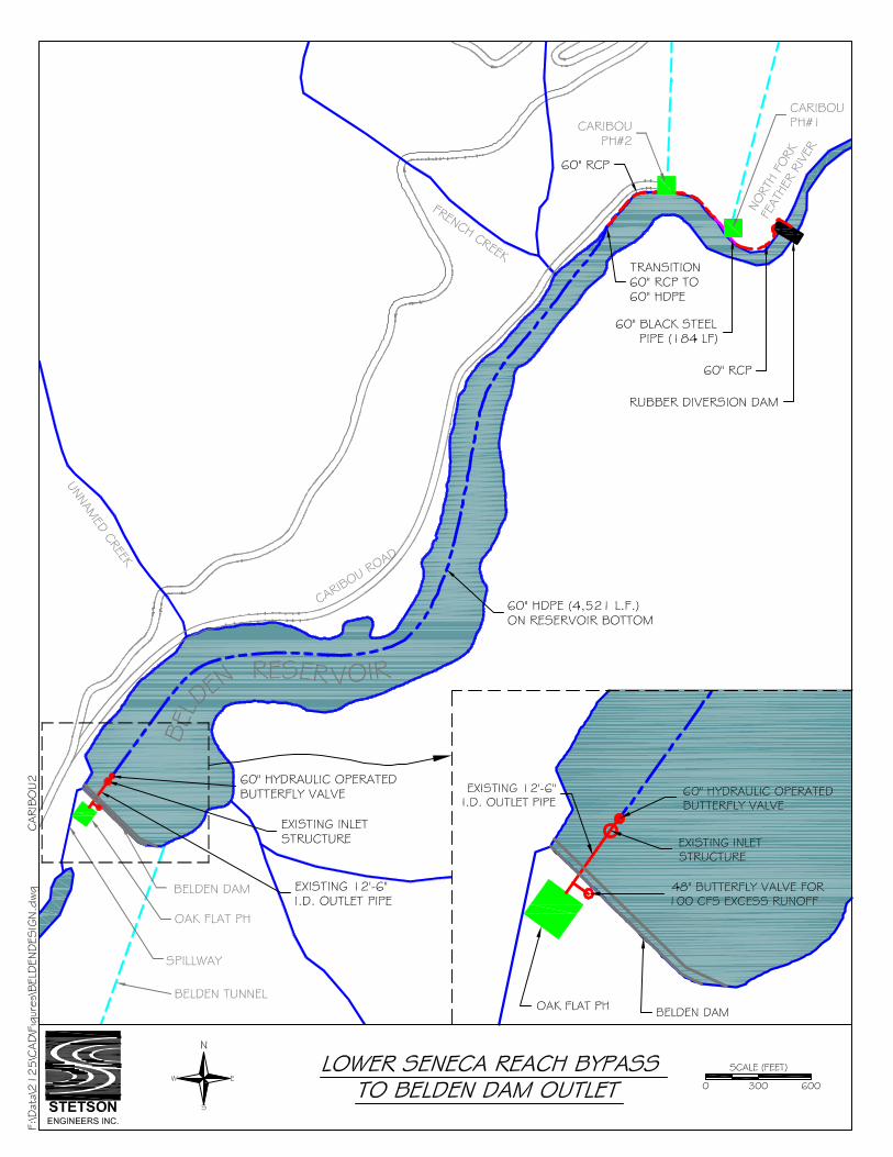
Measure Name: Divert Cool Seneca Reach Flows and Convey by Pipeline to Discharge below Belden Dam Applicable Alternative Category(s): 6a; additional measure for Belden Reach Description of Measure: Construct an approximately 1.1 mile long pipeline to convey cool Seneca Reach flows to below Belden Dam, bypassing Belden Reservoir. The purpose of this measure is to avoid mixing cool Seneca flows with warmer discharges from the Caribou PHs during operational hours and minimize mixing with warmer ambient waters near the surface of Belden Reservoir. Description of Operations: This measure has no affect on PH operations. Operate the diversion system to convey about 250 cfs through the pipeline and spill the remaining flow over the dam. The diversion rate is supplied by the increased release measure from Canyon Dam low-level outlet. The flow accretion along the Seneca Reach, including inflows from lower Butt Creek, would maintain flows for aquatic habitat in the short reach to the Caribou No. 1 discharge. Detailed Description of Facilities Improvements and Design Criteria: Construct a 7-foot high inflatable/deflatable rubber diversion dam at the lower end of Seneca Reach just upstream of Caribou PH No. 1. Except during summer, the rubber dam would remain in the deflated position. Construct an approximately 1.1 mile long pipeline to convey cool Seneca Reach flows captured behind the dam to connect to the existing Oak Flat PH outlet structure for discharge below Belden Dam. The pipeline starts at the diversion dam and extends about 1.1 mile to a submerged diffuser at the bottom of Belden Reservoir. The first segment of the pipeline is about 400 feet long and consists of 60-inch reinforced concrete pipe (RCP) buried into the river bank and covered with riprap. The second segment is about 180 feet long and consists of 60-inch Black Steel Pipe (BSP) which is connected to the concrete face of Caribou PH #1, delivering flows to the northwest bank of the NFFR just upstream of Caribou PH #2. The third segment is about 360 ft long and consists of 60-inch RCP which is buried along the toe of the north bank of the NFFR and protected with riprap. The fourth segment is about 400 feet and consists of 60-inch RCP which is buried along the shoulder of Caribou Road. The fifth and last segment is about 4,520 feet long and consists of 60-inch HPDE pipe that enters Belden Reservoir and is set on and anchored to the bottom of the reservoir. The end of the pipe connects to the existing outlet structure which conveys the flow through a 150-inch conduit to the Oak Flat PH. Because the capacity of the Oak Flat PH turbine is 150 cfs, a 100 cfs outlet from the 150-inch conduit is needed to discharge the flow in excess of the turbine capacity to the Belden Reach. Alternatively, PG&E may choose to increase the capacity of the turbine by 100 cfs.

E-30
List of Figures: • Plan view: Lower Seneca Reach Bypass to Belden Dam Outlet • Profile: Lower Seneca Reach Bypass Key Design or Construction Uncertainties Requiring Further Study: • Setting a 60-inch HDPE along the bottom of Belden Reservoir will be difficult
and costly. Design and installation of an anchoring system adequate to withstand the potential forces on the pipe arising from flow momentum and land shifting requires further study.
• Attaching the end of the 60-inch HDPE pipe to the existing submerged intake and 150-inch outlet pipe will be difficult and costly due to construction underwater.
• Placing and connecting a 60-inch reinforced concrete or black steel pipe to the faces of both powerhouses will require blasting and difficult construction, which could be hazardous due to unstable slopes and recent landslides.
• Pipeline construction beside Caribou Road will require blasting, jack hammering work due to the existing conditions being steep rock cliffs near the powerhouses, which could be hazardous due to unstable slopes and recent landslides.
Discussion: The 60-inch HDPE pipe was not placed along Caribou Road because the elevation gained near the dam would not allow the system to have gravity flow at the design flow rate of 250 cfs.
COST ESTIMATE FOR BYPASSING COOL SENECA REACH FLOWS TO 250 CFS TO BELOW BELDEN DAM
ITEM QUANITY UNIT UNIT COST COST
N FORK FEATHER RIVER RUBBER DAM AND INTAKE AT
CARIBOU PHS 7' high and 39' wide inflatable rubber dam including: mobilization, site
prep, foundation, turnout structure and all necessary materials and construction. 1 LS $1,940,000 $1,940,000
Sub Total NF
Feather River Dam $1,940,000
60" RCP from Rubber Dam to Caribou PH #1
60-inch Reinforced Concrete Pipe, Class 3 400 LF 279 $111,600
Grouted Riprap Slope Protection, 3/8 to 1/4 CY Pieces, 18" Thick 800 SY 120 $96,352
Excavator, Clamshell, 1/2 CY, wet plus addit. Equip 1363 CY 26 $34,934
Backfill, 6" layers, roller compaction operator walking 237 CY 44 $10,376
Compaction, walk behind vibrating plate, 18" wide, 6" lifts, 4 passes 766 CY 3 $2,321
Pipe bedding, crushed rock, 1/2" to 3/4" 529 CY 48 $25,540
1/2 CY bucket wheel mounted front end loader, min haul 1090 CY 16 $17,320
E-31
Hauling, 20 mile round trip, 0.4 loads/ hr (Add 15% for Expansion) 1090 CY 27 $28,994
Sediment and Erosion Control (Silt Fence) 400 LF 5 $2,024
Sub total $329,000
60" Black Steel Pipe along Concrete Face of Caribou PH #1
60" black steel pipe 184 LF 572 $105,248
Drill concrete anchor bolts 184 LF 29 $5,268
Install concrete anchor bolts 184 LF 25 $4,659
Drill & Blast restricted areas 109 CY 214 $23,326
1/2 CY bucket wheel mounted front end loader, min haul 125 CY 16 $1,986
Hauling, 20 mile round trip, 0.4 loads/ hr (Add 15% for Expansion) 125 CY 27 $3,325
Anchor rings 4 EACH 800 $3,200
Precast Storm Drain Manhole, 6' I.D., 8' Deep 2 EACH 4,300 $8,600
Sub total $156,000
60" RCP from Concrete Face of Caribou PH #1 to N Fork Feather
River / Toe of Caribou Road
60-inch Reinforced Concrete Pipe, Class 3 366 LF 279 $102,114
Compaction, walk behind vibrating plate, 18" wide, 6" lifts, 4 passes 682 CY 3 $2,066
Backfill, 6" layers, roller compaction operator walking 198 CY 44 $8,668
Pipe bedding, crushed rock, 1/2" to 3/4" 484 CY 48 $23,368
Remove (load) small boulders (under 1/2 CY) 347 CY 17 $6,062
Replace (load) small boulders (under 1/2 CY) 347 CY 17 $6,062
Excavator, Clamshell, 1/2 CY, wet plus addit. Equip 597 CY 26 $15,301
Drill & Blast in restricted areas 596 CY 214 $127,544
1/2 CY bucket wheel mounted front end loader, min haul 998 CY $16 $15,858
Hauling, 20 mile round trip, 0.4 loads/ hr (Add 15% for Expansion) 998 CY 27 $26,547
Precast Storm Drain Manhole, 6' I.D., 8' Deep 1 EACH 4,300 $4,300
Grouted Riprap Slope Protection, 3/8 to 1/4 CY Pieces, 18" Thick 407 SY 120 $49,019
Sediment and Erosion Control (Silt Fence) 366 LF 5 $1,852
Sub total $389,000
60" RCP from Toe of Caribou Road to 400 feet Downstream
60-inch Reinforced Concrete Pipe, Class 3 400 LF 279 $111,600
Cofferdam, 15-22' Deep, 2 lines of braces, 10" H max 8000 SF 39 $312,000
Compaction, walk behind vibrating plate, 18" wide, 6" lifts, 4 passes 938 CY 3 $2,842
Backfill, 6" layers, roller compaction operator walking 409 CY 44 $17,906
Pipe bedding, crushed rock, 1/2" to 3/4" 529 CY 48 $25,540
Excavator, Clamshell, 1/2 CY, wet plus addit. Equip 771 CY 26 $19,761
Drill & Blast in restricted areas 770 CY 214 $164,780
1/2 CY bucket wheel mounted front end loader, min haul 1090 CY 16 $17,320
Hauling, 20 mile round trip, 0.4 loads/ hr (Add 15% for Expansion) 1090 CY 27 $28,994
Precast Storm Drain Manhole, 6' I.D., 8' Deep 1 EACH 4,300 $4,300
E-32
Grouted Riprap Slope Protection, 3/8 to 1/4 CY Pieces, 18" Thick 569 SY 120 $68,530
Sediment and Erosion Control (Silt Fence) 400 LF 5 2,024
Traffic Control 1 LS 10,000 $10,000
Sub total $786,000
60" HDPE from Toe of Caribou Road to underwater tie in at dam
60-inch HDPE 4521 LF 354 $1,600,434 HDPE Pipe Placement, concrete weight collars / "Float Flood"
method, Mechanical Crane, barge mounted 1 LS 961,000 $961,000
Mechanical Dredging, barge mounted, clamshell, hopper dumped 69622 CY $14 $960,784
Cofferdam, 15-22' Deep, 2 lines of braces, 10" H max 94000 SF 39 $3,666,000
Furnish and place topsoil, truck dumped, screened, 4" deep 2089 SY 4 $8,105
Fine grading with seeding inc lime, fertilizer & seed w/ equip. 188000 SF 6 $1,214,480
Attach to existing plugged inlet structure 1 LS 20,000 $20,000
60-inch hydraulic operated butterfly valve 1 LS 60,000 $60,000
Attach hydraulic valve controls to existing sluice gate controls 1 LS 40,000 $40,000
Sub total $8,531,000
Mobilization
Dozer, above 150 HP (3) 1 LS 3,600 $3,600
Excavator, 1-1.5 CY Diesel Hyd. (2) 1 LS 9,600 $9,600
Loader (2) 1 LS 2,400 $2,400
Dump truck, 26 tons (10) 1 LS 6,000 $6,000
25 ton truck mounted hydraulic crane (2) 1 LS 2,000 $2,000
Crawler Type Drill, 4" (1) 1 LS 700 $700
Grout pumper (1) 1 LS 600 $600
Water truck, 6000 gal (1) 1 LS 600 $600
Wash & Screen (1) 1 LS 7,200 $7,200 Mechanical Dredger / Crane, barge mounted and all loading
equipment 1 LS 200,000 $200,000
Sub total Mob /
Demob $233,000
TOTAL $12,364,000


E-33
Measure Name: Divert Warm Water from East Branch NFFR into a Pipeline to Discharge into Upper Rock Creek Reservoir Applicable Alternative Category(s): 3, 4, 5a, 6a; additional measure for Belden Reach Description of Measure: Construct about 1.8-mile long pipeline to convey warm water from East Branch NFFR to discharge into upper Rock Creek Reservoir. The purpose of this measure is to protect the lower Belden Reach from the warming effects of East Branch NFFR inflows. Description of Operations: This measure does not affect PH operations. According to PG&E’s flow measurements in summer 2002-2004, flows in East Branch NFFR during July and August ranged from 45 cfs to 150 cfs, and were less than 100 cfs most of time. A diversion rate of 100 cfs from the East Branch NFFR was used as design flow for this measure. Spill 10 cfs over the rubber dam to maintain instream flow for aquatic habitat in the remaining short reach of the East Branch to the NFFR. Detailed Description of Facilities Improvements and Design Criteria: Construct a 3-foot high inflatable/deflatable rubber diversion dam at the lower end of the East Branch NFFR about 300 feet upstream from the NFFR confluence. Except during summer, the rubber dam would remain in the deflated position. Construct an approximately 1.8 mile long, 48-inch RCP pipeline to convey the warm water flows captured behind the dam to discharge into Rock Creek Reservoir. The pipeline discharges through a manually operated butterfly valve to the NFFR just upstream of the Yellow Creek confluence. Flows in the NFFR above the East Branch during July and August exhibited an average temperature of about 22.5 °C (ranging from 19.9 °C to 26.4 °C), ranged from 45 cfs to 150 cfs, and were less than 100 cfs most of time. These flows would maintain aquatic habitat along the lower Belden Reach. List of Figures:
• Plan view: East Branch Feather River to Rock Creek Reservoir • Profile: East Branch to Rock Creek Reservoir
Key Design or Construction Uncertainties Requiring Further Study:
• Construction of the 48-inch reinforced concrete pipe close to the channel along the south bank of the NFFR will be difficult and costly due to boulders and water in the channel.
Discussion: This measure is slightly different when it is incorporated into alternatives in Alternative Categories 5 and 6. In these alternatives, warm water conveyed from the East Branch NFFR is discharged farther upstream of the Yellow Creek confluence in order to better integrate with the diversion and conveyance of cool lower Belden flows for plunging or bypassing Rock Creek Reservoir.

E-34
COST ESTIMATE FOR CONVEYING EAST BRANCH NFFR FLOWS TO UPPER ROCK CREEK RESERVOIR
ITEM QUANITY UNIT UNIT COST COST
RUBBER DAM AND INTAKE 3' high and 66' wide inflatable rubber dam including: mobilization, site
prep, foundation, turnout structure and all necessary materials and construction. 1 LS $1,400,000 $1,400,000
Sub Total $1,400,000
Access Road (1000-foot Access Road from Howells Road)
Sediment and Erosion Control (Silt Fence) 955 LF 5 $4,829
Clearing (including Trees), Dozer 300 HP 2334 SY 6 $13,957
Excavation, Road and Retaining Wall Footings, 1CY Truck Mounted Hydr. 706 CY 13 $9,501
Hauling, 12 CY Dump Truck, 20-mile RT, 0.4 Loads / Hour 706 CY 38 $27,133
Concrete for Retaining Wall Footings 39 CY 1,900 $73,530
Steel Galv. Retaining Wall Posts, 8-Foot 14 EACH 84 $1,191
Treated Wood for Retaining Wall 28483 BF 12 $336,636
Fill, 1/2 to 3/4" Crushed Rock 686 CY 47 $32,376
Fill, Road Surface Gravel 221 CY 36 $8,010
Sub Total $507,000
48" Pipe From Dam to Howells Road
48-inch Reinforced Concrete Pipe 2700 LF 104 $281,232
1/2 CY bucket wheel mounted front end loader, min haul 4140 CY 16 $65,785
Hauling, 20 mile round trip, 0.4 loads/ hr (Add 15% for Expansion) 4140 CY 27 $110,124
Compaction, walk behind vibrating plate, 18" wide, 6" lifts, 4 passes 2943 CY 3 $8,917
Pipe bedding, crushed rock, 1/2" to 3/4" 2343 CY 48 $113,120 Excavation, truck mounted, 6-10' deep, 1 CY excavator, Hydraulic Jack hammer 4200 CY 12 $50,400
Grouted Riprap Slope Protection, 3/8 to 1/4 CY Pieces, 18" Thick 80 SY 120 $9,635
Precast Storm Drain Manhole, 4' I.D., 8' Deep 2 EACH 1,900 $3,800
Sub Total $643,000
48" Pipe in Howells Road
48-inch Reinforced Concrete Pipe 6104 LF 104 $635,793
Sawcut Asphalt, 4" Thick 8400 LF 2 $19,572
Pavement Removal, Bituminous Roads 4" to 6" 3733 SF 8 $28,968
Pavement Replacement Over Trench, 4" Thick 3733 SF 35 $131,626
1/2 CY bucket wheel mounted front end loader, min haul 5665 CY 16 $90,017
Hauling, 20 mile round trip, 0.4 loads/ hr (Add 15% for Expansion) 5665 CY 27 $150,689
Compaction, walk behind vibrating plate, 18" wide, 6" lifts, 4 passes 4578 CY 3 $13,871
Pipe bedding, crushed rock, 1/2" to 3/4" 3645 CY 48 $175,981

E-35
Excavation, truck mounted, 6-10' deep, 1 CY excavator, Hydraulic Jack hammer 6533 CY 12 $78,396
Precast Storm Drain Manhole, 4' I.D., 8' Deep 6 EACH 1,900 $11,400
Traffic Control 1 EACH 10,000 $10,000
Sub Total $1,346,000
48" Pipe from Howells Road to Outlet
48-inch Reinforced Concrete Pipe 260 LF 104 $27,082
1/2 CY bucket wheel mounted front end loader, min haul 150 CY 16 $2,384
Hauling, 20 mile round trip, 0.4 loads/ hr (Add 15% for Expansion) 150 CY 27 $3,990
Compaction, walk behind vibrating plate, 18" wide, 6" lifts, 4 passes 163 CY 3 $494
Pipe bedding, crushed rock, 1/2" to 3/4" 130 CY 48 $6,276 Excavation, truck mounted, 6-10' deep, 1 CY excavator, Hydraulic Jack hammer 233 CY 12 $2,796
Grouted Riprap Slope Protection, 3/8 to 1/4 CY Pieces, 18" Thick 156 SY 120 $18,789
48-inch hydraulic operated butterfly valve 1 LS 47,000 $47,000
Concrete Outlet Structure 10 CY 1,900 $19,000
Grouted Riprap Slope Protection for Outlet Structure 75 SY 120 $9,000
Sub Total $137,000
Mobilization
Dozer, above 150 HP (2) 1 LS 2,400 $2,400
Excavator, 1-1.5 CY Diesel Hyd. Mobilization 1 EACH 4,800 $4,800
Loader (2) 1 LS 2,400 $2,400
Paver Mobilization 1 LS 1,200 $1,200
Grout pumper (1) 1 LS 600 $600
Dump truck, 26 tons (4) 1 LS 2,400 $2,400
Grader, 30,000 lbs (1) 1 LS 1,200 $1,200
Sub Total $15,000
TOTAL $4,048,000
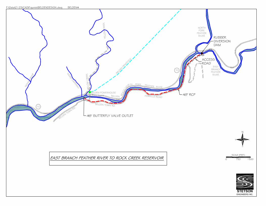

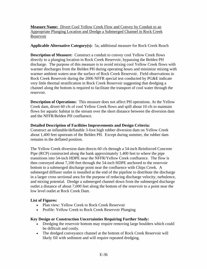
E-36
Measure Name: Divert Cool Yellow Creek Flow and Convey by Conduit to an Appropriate Plunging Location and Dredge a Submerged Channel in Rock Creek Reservoir Applicable Alternative Category(s): 5a; additional measure for Rock Creek Reach Description of Measure: Construct a conduit to convey cool Yellow Creek flows directly to a plunging location in Rock Creek Reservoir, bypassing the Belden PH discharge. The purpose of this measure is to avoid mixing cool Yellow Creek flows with warmer discharges from the Belden PH during operating hours and minimize mixing with warmer ambient waters near the surface of Rock Creek Reservoir. Field observations in Rock Creek Reservoir during the 2006 NFFR special test conducted by PG&E indicate very little thermal stratification in Rock Creek Reservoir suggesting that dredging a channel along the bottom is required to facilitate the transport of cool water through the reservoir. Description of Operations: This measure does not affect PH operations. At the Yellow Creek dam, divert 60 cfs of cool Yellow Creek flows and spill about 10 cfs to maintain flows for aquatic habitat in the stream over the short distance between the diversion dam and the NFFR/Belden PH confluence. Detailed Description of Facilities Improvements and Design Criteria: Construct an inflatable/deflatable 3-foot high rubber diversion dam on Yellow Creek about 1,400 feet upstream of the Belden PH. Except during summer, the rubber dam remains in the deflated position. The Yellow Creek diversion dam directs 60 cfs through a 54-inch Reinforced Concrete Pipe (RCP) constructed along the bank approximately 1,400 feet to where the pipe transitions into 54-inch HDPE near the NFFR/Yellow Creek confluence. The flow is then conveyed about 7,100 feet through the 54-inch HDPE anchored to the reservoir bottom to a submerged discharge point near the confluence with Chips Creek. A submerged diffuser outlet is installed at the end of the pipeline to distribute the discharge in a larger cross sectional area for the purpose of reducing discharge velocity, turbulence, and mixing potential. Dredge a submerged channel down from the submerged discharge outlet a distance of about 7,000 feet along the bottom of the reservoir to a point near the low level outlet at Rock Creek Dam. List of Figures:
• Plan view: Yellow Creek to Rock Creek Reservoir • Profile: Yellow Creek to Rock Creek Reservoir Plunging
Key Design or Construction Uncertainties Requiring Further Study:
• Dredging the reservoir bottom may require removing large boulders which could be difficult and costly.
• The dredged conveyance channel at the bottom of Rock Creek Reservoir will likely fill with sediment and will require repeated dredging.
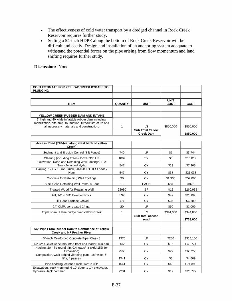
E-37
• The effectiveness of cold water transport by a dredged channel in Rock Creek Reservoir requires further study.
• Setting a 54-inch HDPE along the bottom of Rock Creek Reservoir will be difficult and costly. Design and installation of an anchoring system adequate to withstand the potential forces on the pipe arising from flow momentum and land shifting requires further study.
Discussion: None
COST ESTIMATE FOR YELLOW CREEK BYPASS TO PLUNGING
ITEM QUANITY UNIT UNIT COST COST
YELLOW CREEK RUBBER DAM AND INTAKE 3' high and 40' wide inflatable rubber dam including:
mobilization, site prep, foundation, turnout structure and all necessary materials and construction. 1 LS $850,000 $850,000
Sub Total Yellow
Creek Dam $850,000
Access Road (710-feet along west bank of Yellow
Creek)
Sediment and Erosion Control (Silt Fence) 740 LF $5 $3,744
Clearing (including Trees), Dozer 300 HP 1809 SY $6 $10,819 Excavation, Road and Retaining Wall Footings, 1CY
Truck Mounted Hydr. 547 CY $13 $7,365 Hauling, 12 CY Dump Truck, 20-mile RT, 0.4 Loads /
Hour 547 CY $38 $21,033
Concrete for Retaining Wall Footings 30 CY $1,900 $57,000
Steel Galv. Retaining Wall Posts, 8-Foot 11 EACH $84 $923
Treated Wood for Retaining Wall 22080 BF $12 $260,958
Fill, 1/2 to 3/4" Crushed Rock 532 CY $47 $25,098
Fill, Road Surface Gravel 171 CY $36 $6,209
24" CMP, corrugated 14 ga. 20 LF $50 $1,009
Triple span, 1 lane bridge over Yellow Creek 1 LS $344,000 $344,000
Sub total access
road $738,000
54" Pipe From Rubber Dam to Confluence of Yellow
Creek and NF Feather River
54-inch Reinforced Concrete Pipe, Class 3 1370 LF $230 $315,100
1/2 CY bucket wheel mounted front end loader, min haul 2566 CY $16 $40,774 Hauling, 20 mile round trip, 0.4 loads/ hr (Add 15% for
Expansion) 2566 CY $27 $68,256 Compaction, walk behind vibrating plate, 18" wide, 6"
lifts, 4 passes 1541 CY $3 $4,669
Pipe bedding, crushed rock, 1/2" to 3/4" 1541 CY $48 $74,399 Excavation, truck mounted, 6-10' deep, 1 CY excavator, Hydraulic Jack hammer 2231 CY $12 $26,772

E-38
Precast Storm Drain Manhole, 4' I.D., 8' Deep 4 EACH $1,900 $7,600
Concrete Encasement Under Hwy 70 43 CY $1,125 $48,370 Grouted Riprap Slope Protection, 3/8 to 1/4 CY Pieces,
18" Thick 100 SY $120 $12,044
Sawcut Asphalt, 4" Thick 122 LF $2 $284
Pavement Removal, Bituminous Roads 4" to 6" 396 SF $8 $3,073
Pavement Replacement Over Trench, 4" Thick 396 SF $35 $13,963
Traffic Control 1 EACH $5,000 $5,000
Sub total 54"
RCP $620,000
54-Inch HDPE From Confluence of Yellow Creek and
NFFR to Chips Creek (With Dredging to Dam)
54-inch HDPE 2640 LF $271 $715,440 HDPE Pipe Placement, S-lay method with stinger,
Mechanical Crane, barge mounted 1 LS $1,700,000 $1,700,000 Mechanical Dredging, barge mounted, clamshell, hopper
dumped 130256 CY $13 $1,667,277
Cofferdam, 15-22' Deep, 2 lines of braces, 10" H max 117200 SF $39 $4,570,800 Furnish and place topsoil, truck dumped, screened, 4"
deep 39067 SY $4 $151,580 Fine grading with seeding inc lime, fertilizer & seed w/
equip. 351600 SF $6 $2,271,336 Concrete Outlet Diffuser Structure, Structure Pad and
Rock Cover 1 LS $15,000 $15,000
Sub total 54"
HDPE $11,091,000
Mobilization
Dozer, above 150 HP (3) 1 LS $3,600 $3,600
Excavator, 1-1.5 CY Diesel Hyd. (2) 1 LS $9,600 $9,600
Loader (2) 1 LS $2,400 $2,400
Paver Mobilization 1 LS $1,200 $1,200
Grout pumper (1) 1 LS $600 $600 Mechanical Dredger, Crane and stinger, barge mounted
and all equipment 1 LS $200,000 $200,000
Sub total Mob /
Demob $217,000
TOTAL $13,516,000
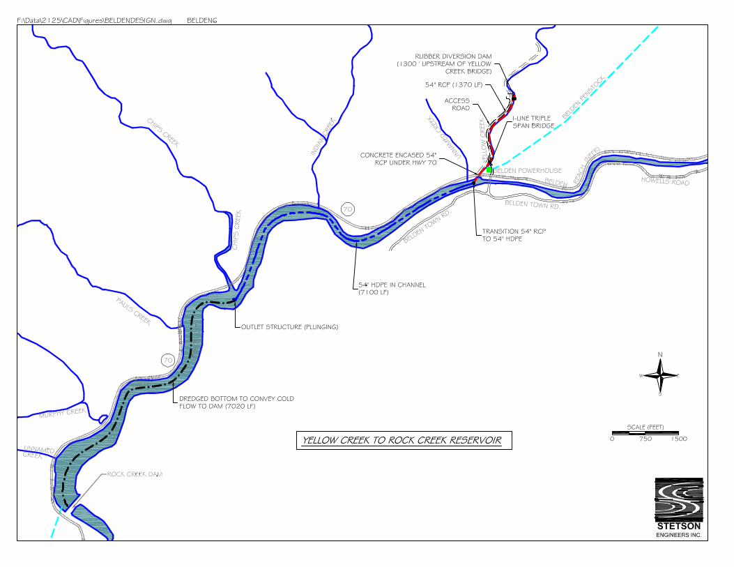
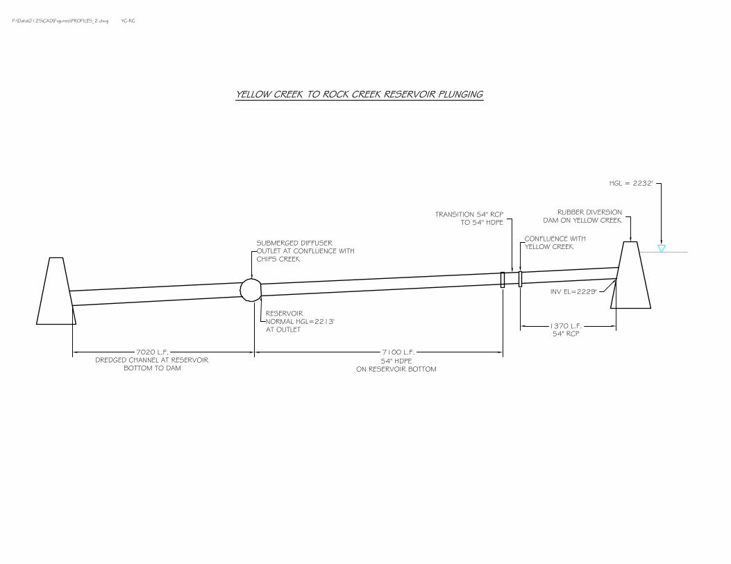
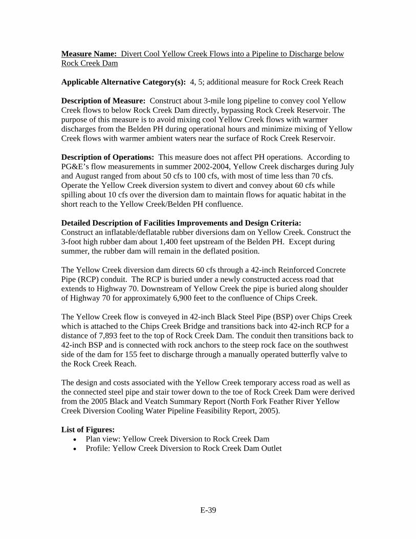
E-39
Measure Name: Divert Cool Yellow Creek Flows into a Pipeline to Discharge below Rock Creek Dam Applicable Alternative Category(s): 4, 5; additional measure for Rock Creek Reach Description of Measure: Construct about 3-mile long pipeline to convey cool Yellow Creek flows to below Rock Creek Dam directly, bypassing Rock Creek Reservoir. The purpose of this measure is to avoid mixing cool Yellow Creek flows with warmer discharges from the Belden PH during operational hours and minimize mixing of Yellow Creek flows with warmer ambient waters near the surface of Rock Creek Reservoir. Description of Operations: This measure does not affect PH operations. According to PG&E’s flow measurements in summer 2002-2004, Yellow Creek discharges during July and August ranged from about 50 cfs to 100 cfs, with most of time less than 70 cfs. Operate the Yellow Creek diversion system to divert and convey about 60 cfs while spilling about 10 cfs over the diversion dam to maintain flows for aquatic habitat in the short reach to the Yellow Creek/Belden PH confluence. Detailed Description of Facilities Improvements and Design Criteria: Construct an inflatable/deflatable rubber diversions dam on Yellow Creek. Construct the 3-foot high rubber dam about 1,400 feet upstream of the Belden PH. Except during summer, the rubber dam will remain in the deflated position. The Yellow Creek diversion dam directs 60 cfs through a 42-inch Reinforced Concrete Pipe (RCP) conduit. The RCP is buried under a newly constructed access road that extends to Highway 70. Downstream of Yellow Creek the pipe is buried along shoulder of Highway 70 for approximately 6,900 feet to the confluence of Chips Creek. The Yellow Creek flow is conveyed in 42-inch Black Steel Pipe (BSP) over Chips Creek which is attached to the Chips Creek Bridge and transitions back into 42-inch RCP for a distance of 7,893 feet to the top of Rock Creek Dam. The conduit then transitions back to 42-inch BSP and is connected with rock anchors to the steep rock face on the southwest side of the dam for 155 feet to discharge through a manually operated butterfly valve to the Rock Creek Reach. The design and costs associated with the Yellow Creek temporary access road as well as the connected steel pipe and stair tower down to the toe of Rock Creek Dam were derived from the 2005 Black and Veatch Summary Report (North Fork Feather River Yellow Creek Diversion Cooling Water Pipeline Feasibility Report, 2005). List of Figures:
• Plan view: Yellow Creek Diversion to Rock Creek Dam • Profile: Yellow Creek Diversion to Rock Creek Dam Outlet
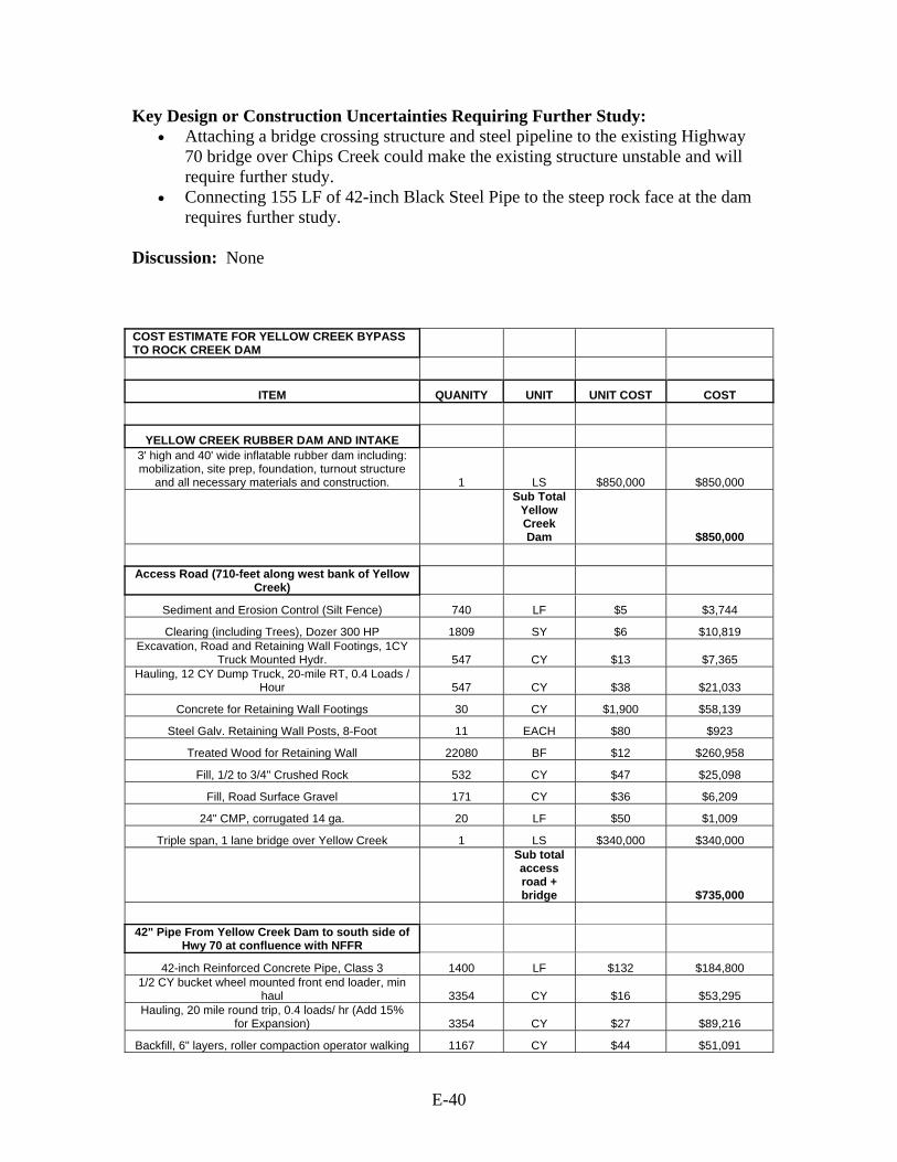
E-40
Key Design or Construction Uncertainties Requiring Further Study: • Attaching a bridge crossing structure and steel pipeline to the existing Highway
70 bridge over Chips Creek could make the existing structure unstable and will require further study.
• Connecting 155 LF of 42-inch Black Steel Pipe to the steep rock face at the dam requires further study.
Discussion: None COST ESTIMATE FOR YELLOW CREEK BYPASS TO ROCK CREEK DAM
ITEM QUANITY UNIT UNIT COST COST
YELLOW CREEK RUBBER DAM AND INTAKE 3' high and 40' wide inflatable rubber dam including: mobilization, site prep, foundation, turnout structure
and all necessary materials and construction. 1 LS $850,000 $850,000
Sub Total Yellow Creek Dam $850,000
Access Road (710-feet along west bank of Yellow
Creek)
Sediment and Erosion Control (Silt Fence) 740 LF $5 $3,744
Clearing (including Trees), Dozer 300 HP 1809 SY $6 $10,819 Excavation, Road and Retaining Wall Footings, 1CY
Truck Mounted Hydr. 547 CY $13 $7,365 Hauling, 12 CY Dump Truck, 20-mile RT, 0.4 Loads /
Hour 547 CY $38 $21,033
Concrete for Retaining Wall Footings 30 CY $1,900 $58,139
Steel Galv. Retaining Wall Posts, 8-Foot 11 EACH $80 $923
Treated Wood for Retaining Wall 22080 BF $12 $260,958
Fill, 1/2 to 3/4" Crushed Rock 532 CY $47 $25,098
Fill, Road Surface Gravel 171 CY $36 $6,209
24" CMP, corrugated 14 ga. 20 LF $50 $1,009
Triple span, 1 lane bridge over Yellow Creek 1 LS $340,000 $340,000
Sub total access road + bridge $735,000
42" Pipe From Yellow Creek Dam to south side of
Hwy 70 at confluence with NFFR
42-inch Reinforced Concrete Pipe, Class 3 1400 LF $132 $184,800 1/2 CY bucket wheel mounted front end loader, min
haul 3354 CY $16 $53,295 Hauling, 20 mile round trip, 0.4 loads/ hr (Add 15%
for Expansion) 3354 CY $27 $89,216
Backfill, 6" layers, roller compaction operator walking 1167 CY $44 $51,091

E-41
Pipe bedding, crushed rock, 1/2" to 3/4" 1685 CY $48 $81,352 Excavation, truck mounted, 6-10' deep, 1 CY excavator, Hydraulic Jack hammer 4083 CY $12 $48,996
Precast Storm Drain Manhole, 5' I.D., 8' Deep 4 EACH $3,000 $11,176
Concrete Encasement Under Hwy 70 65 CY $1,100 $73,118 Grouted Riprap Slope Protection, 3/8 to 1/4 CY
Pieces, 18" Thick 100 SY $120 $12,044
Sawcut Asphalt, 4" Thick 122 LF $2 $284
Pavement Removal, Bituminous Roads 4" to 6" 396 SF $8 $3,073
Pavement Replacement Over Trench, 4" Thick 396 SF $35 $13,963
Traffic Control 1 EACH $5,000 $5,000
Sub total $627,000
42" Pipe From south side of Hwy 70 at confluence
with NFFR to Chips Creek
Clearing, medium 1 ACRE $1,400 $1,400
42-inch Reinforced Concrete Pipe, Class 3 6913 LF $132 $912,516 1/2 CY bucket wheel mounted front end loader, min
haul 16562 CY $16 $263,170 Hauling, 20 mile round trip, 0.4 loads/ hr (Add 15%
for Expansion) 16562 CY $27 $440,549
Backfill, 6" layers, roller compaction operator walking 5761 CY $44 $252,217
Pipe bedding, crushed rock, 1/2" to 3/4" 8319 CY $48 $401,641 Excavation, truck mounted, 6-10' deep, 1 CY excavator, Hydraulic Jack hammer 20163 CY $12 $241,956
Remove Gravel shoulder 1874 SY $7 $12,481
Replace Gravel shoulder 625 CY $48 $30,175 Grouted Riprap Slope Protection, 3/8 to 1/4 CY
Pieces, 18" Thick 9471 SY $120 $1,140,687
Sediment and Erosion Control (Silt Fence) 6913 LF $5 $34,980 Remove and reset existing corrugated metal guard
rail (includes all guard rail on 70) 12940 LF $35 $449,277
Precast Storm Drain Manhole, 5' I.D., 8' Deep 20 EACH $3,000 $60,000 Traffic control, signage (includes traffic cont. down to
dam) 1 LS $30,000 $30,000 Traffic control, 2 signals (includes traffic cont. down
to dam) 1 LS $380,000 $380,000
Sub total $4,651,000
Chips Creek at Hwy 70 to top of Rock Creek Dam
Clearing, medium 1 ACRE $1,400 $1,400
42-inch Reinforced Concrete Pipe, Class 3 7893 LF $132 $1,041,876 Excavation, truck mounted, 6-10' deep, 1 CY
excavator, Hydraulic Jack hammer 28576 CY $12 $342,912 1/2 CY bucket wheel mounted front end loader, min
haul 24289 CY $16 $385,952
Backfill, 6" layers, roller compaction operator walking 7455 CY $44 $326,380
Pipe bedding, crushed rock, 1/2" to 3/4" 11421 CY $48 $551,406 Hauling, 20 mile round trip, 0.4 loads/ hr (Add 15%
for Expansion) 24289 CY $27 $646,087
Precast Storm Drain Manhole, 6' I.D., 8' Deep 34 EACH $4,000 $136,000 Grouted Riprap Slope Protection, 3/8 to 1/4 CY
Pieces, 18" Thick 11690 SY $120 $1,407,944
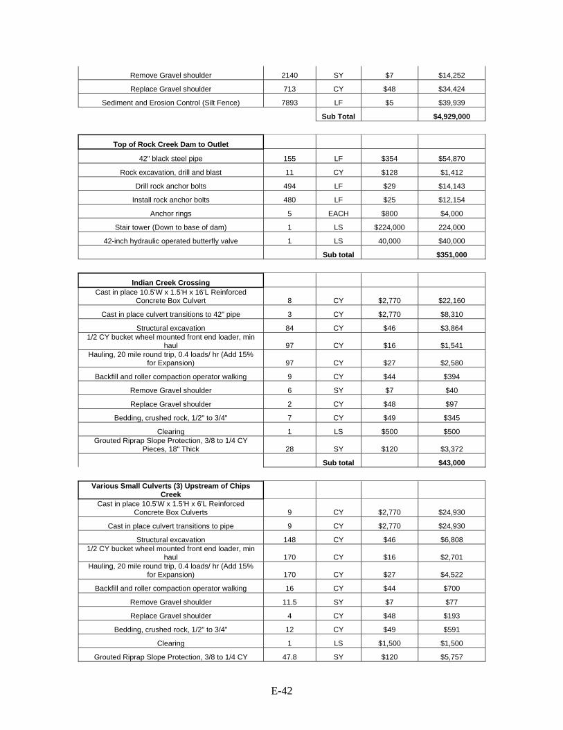
E-42
Remove Gravel shoulder 2140 SY $7 $14,252
Replace Gravel shoulder 713 CY $48 $34,424
Sediment and Erosion Control (Silt Fence) 7893 LF $5 $39,939
Sub Total $4,929,000
Top of Rock Creek Dam to Outlet
42" black steel pipe 155 LF $354 $54,870
Rock excavation, drill and blast 11 CY $128 $1,412
Drill rock anchor bolts 494 LF $29 $14,143
Install rock anchor bolts 480 LF $25 $12,154
Anchor rings 5 EACH $800 $4,000
Stair tower (Down to base of dam) 1 LS $224,000 224,000
42-inch hydraulic operated butterfly valve 1 LS 40,000 $40,000
Sub total $351,000
Indian Creek Crossing Cast in place 10.5'W x 1.5'H x 16'L Reinforced
Concrete Box Culvert 8 CY $2,770 $22,160
Cast in place culvert transitions to 42" pipe 3 CY $2,770 $8,310
Structural excavation 84 CY $46 $3,864 1/2 CY bucket wheel mounted front end loader, min
haul 97 CY $16 $1,541 Hauling, 20 mile round trip, 0.4 loads/ hr (Add 15%
for Expansion) 97 CY $27 $2,580
Backfill and roller compaction operator walking 9 CY $44 $394
Remove Gravel shoulder 6 SY $7 $40
Replace Gravel shoulder 2 CY $48 $97
Bedding, crushed rock, 1/2" to 3/4" 7 CY $49 $345
Clearing 1 LS $500 $500 Grouted Riprap Slope Protection, 3/8 to 1/4 CY
Pieces, 18" Thick 28 SY $120 $3,372
Sub total $43,000
Various Small Culverts (3) Upstream of Chips
Creek Cast in place 10.5'W x 1.5'H x 6'L Reinforced
Concrete Box Culverts 9 CY $2,770 $24,930
Cast in place culvert transitions to pipe 9 CY $2,770 $24,930
Structural excavation 148 CY $46 $6,808 1/2 CY bucket wheel mounted front end loader, min
haul 170 CY $16 $2,701 Hauling, 20 mile round trip, 0.4 loads/ hr (Add 15%
for Expansion) 170 CY $27 $4,522
Backfill and roller compaction operator walking 16 CY $44 $700
Remove Gravel shoulder 11.5 SY $7 $77
Replace Gravel shoulder 4 CY $48 $193
Bedding, crushed rock, 1/2" to 3/4" 12 CY $49 $591
Clearing 1 LS $1,500 $1,500
Grouted Riprap Slope Protection, 3/8 to 1/4 CY 47.8 SY $120 $5,757
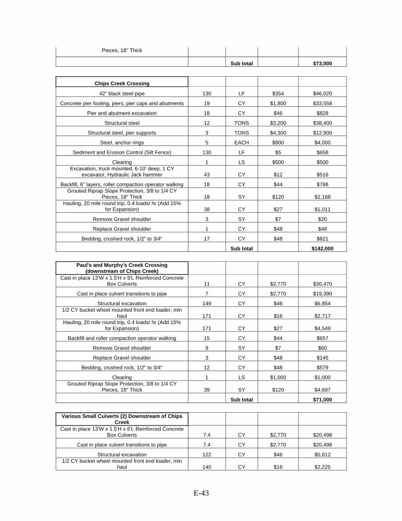
E-43
Pieces, 18" Thick
Sub total $73,000
Chips Creek Crossing
42" black steel pipe 130 LF $354 $46,020
Concrete pier footing, piers, pier caps and abutments 19 CY $1,800 $33,558
Pier and abutment excavation 18 CY $46 $828
Structural steel 12 TONS $3,200 $38,400
Structural steel, pier supports 3 TONS $4,300 $12,900
Steel, anchor rings 5 EACH $800 $4,000
Sediment and Erosion Control (Silt Fence) 130 LF $5 $658
Clearing 1 LS $500 $500 Excavation, truck mounted, 6-10' deep, 1 CY
excavator, Hydraulic Jack hammer 43 CY $12 $516
Backfill, 6" layers, roller compaction operator walking 18 CY $44 $788 Grouted Riprap Slope Protection, 3/8 to 1/4 CY
Pieces, 18" Thick 18 SY $120 $2,168 Hauling, 20 mile round trip, 0.4 loads/ hr (Add 15%
for Expansion) 38 CY $27 $1,011
Remove Gravel shoulder 3 SY $7 $20
Replace Gravel shoulder 1 CY $48 $48
Bedding, crushed rock, 1/2" to 3/4" 17 CY $48 $821
Sub total $142,000
Paul's and Murphy's Creek Crossing
(downstream of Chips Creek) Cast in place 13'W x 1.5'H x 9'L Reinforced Concrete
Box Culverts 11 CY $2,770 $30,470
Cast in place culvert transitions to pipe 7 CY $2,770 $19,390
Structural excavation 149 CY $46 $6,854 1/2 CY bucket wheel mounted front end loader, min
haul 171 CY $16 $2,717 Hauling, 20 mile round trip, 0.4 loads/ hr (Add 15%
for Expansion) 171 CY $27 $4,549
Backfill and roller compaction operator walking 15 CY $44 $657
Remove Gravel shoulder 9 SY $7 $60
Replace Gravel shoulder 3 CY $48 $145
Bedding, crushed rock, 1/2" to 3/4" 12 CY $48 $579
Clearing 1 LS $1,000 $1,000 Grouted Riprap Slope Protection, 3/8 to 1/4 CY
Pieces, 18" Thick 39 SY $120 $4,697
Sub total $71,000
Various Small Culverts (2) Downstream of Chips
Creek Cast in place 13'W x 1.5'H x 6'L Reinforced Concrete
Box Culverts 7.4 CY $2,770 $20,498
Cast in place culvert transitions to pipe 7.4 CY $2,770 $20,498
Structural excavation 122 CY $46 $5,612 1/2 CY bucket wheel mounted front end loader, min
haul 140 CY $16 $2,225

E-44
Hauling, 20 mile round trip, 0.4 loads/ hr (Add 15% for Expansion) 140 CY $27 $3,724
Backfill and roller compaction operator walking 13 CY $44 $569
Remove Gravel shoulder 8 SY $7 $53
Replace Gravel shoulder 3 CY $48 $145
Bedding, crushed rock, 1/2" to 3/4" 10 CY $49 $493
Clearing 1 LS $1,500 $1,500 Grouted Riprap Slope Protection, 3/8 to 1/4 CY
Pieces, 18" Thick 32 SY $120 $3,854
Sub total $59,000
Mobilization / Demobilization
Dozer, above 150 HP (3) 1 LS $3,600 $3,600
Excavator, 1-1.5 CY Diesel Hyd. (2) 1 LS $9,600 $9,600
Loader (2) 1 LS $2,400 $2,400
Dump truck, 26 tons (10) 1 LS $6,000 $6,000
25 ton truck mounted hydraulic crane (2) 1 LS $2,000 $2,000
Crawler Type Drill, 4" (1) 1 LS $700 $700
Grader, 30,000 lbs (2) 1 LS $2,400 $2,400
Grout pumper (1) 1 LS $600 $600
Water truck, 6000 gal (2) 1 LS $1,200 $1,200
Wash & Screen (1) 1 LS $7,200 $7,200
Sub total $36,000
Total $12,567,000
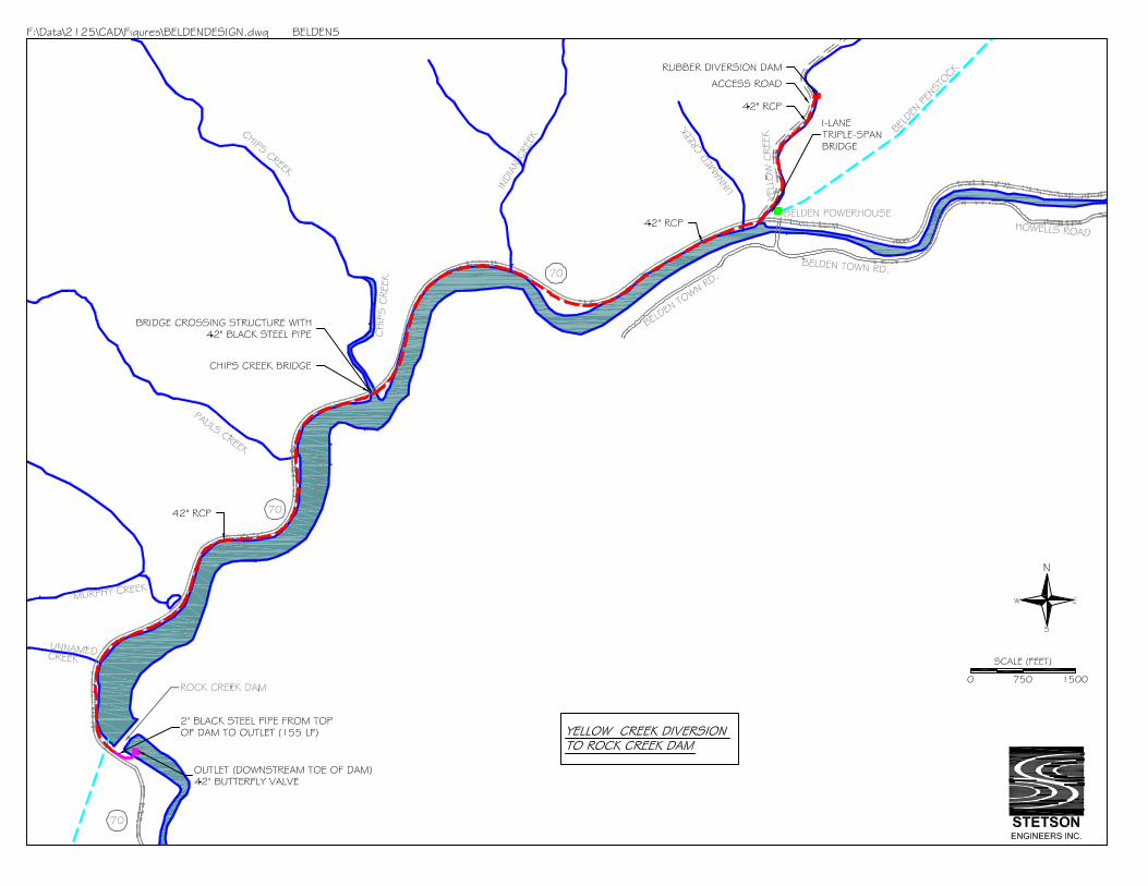

E-45
Measure Name: Divert Cool Yellow Creek and Chips Creek Flows into a Pipeline to Discharge below Rock Creek Dam Applicable Alternative Category(s): 4, 5; additional measure for Rock Creek Reach Description of Measure: Construct about 3-mile long pipeline to convey cool Yellow Creek and Chips Creek flows to below Rock Creek Dam directly, bypassing Rock Creek Reservoir. The purpose of this measure is to avoid mixing cool Yellow Creek flows with warmer discharges from the Belden PH during operational hours and minimize mixing of Yellow Creek and Chips Creek flows with warmer ambient waters near the surface of Rock Creek Reservoir. Description of Operations: This measure does not affect PH operations. According to PG&E’s flow measurements in summer 2002-2004, Yellow Creek discharges during July and August ranged from about 50 cfs to 100 cfs, with most of time less than 70 cfs. Chips Creek discharges during July and August ranged from about 15 cfs to 50 cfs, with most of time less than 30 cfs. Operate the Yellow Creek diversion system to divert and convey about 60 cfs while spilling about 10 cfs over the diversion dam to maintain flows for aquatic habitat in the short reach to the Yellow Creek/Belden PH confluence. Operate the Chips Creek diversion system to divert and convey about 20 cfs while spilling about 3 cfs over the diversion dam to maintain flows for aquatic habitat in the short reach to Rock Creek Reservoir. Detailed Description of Facilities Improvements and Design Criteria: Construct two inflatable/deflatable rubber diversions dams; one on Yellow Creek and another on Chips Creek. On Yellow Creek, construct a 3-foot high rubber about 1,400 feet upstream of the Belden PH. On Chips Creek construct a 3-foot high rubber about 740 feet upstream of Highway 70 above Rock Creek Reservoir. Except during summer, the rubber dams remain in the deflated position. The Yellow Creek diversion dam directs 60 cfs through a 54-inch Reinforced Concrete Pipe (RCP) conduit. The RCP is buried under a newly constructed access road that extends to Highway 70. Downstream of Yellow Creek the pipe is buried along shoulder of Highway 70 for approximately 6,900 feet to the confluence of Chips Creek. The Chips Creek diversion dam directs 20 cfs through a 18-inch RCP which is buried for a distance of about 740 feet along the east bank of Chips Creek. The Yellow Creek and Chips Creek RCPs join at a tie-in structure at Highway 70. The combined 80 cfs is conveyed in 60-inch Black Steel Pipe (BSP) that is attached to the Chips Creek Bridge over Chips Creek and transitions back into 60-inch RCP for a distance of 7,893 feet to the top of Rock Creek Dam. The conduit then transitions back to 60-inch BSP and is connected with rock anchors to the steep rock face on the southwest side of the dam for 155 feet to discharge through a manually operated butterfly valve to the Rock Creek Reach.
E-46
The design and costs associated with the Yellow Creek temporary access road as well as the bolted steel pipe and stair tower down to the toe of Rock Creek Dam were derived from the 2005 Black and Veatch Summary Report (North Fork Feather River Yellow Creek Diversion Cooling Water Pipeline Feasibility Report, 2005) List of Figures:
• Plan view: Yellow and Chips Creek Diversion to Rock Creek Dam • Profile: Yellow and Chips Creek Diversion to Rock Creek Dam
Key Design or Construction Uncertainties Requiring Further Study:
• Attaching a bridge crossing structure and steel pipeline to the existing Highway 70 bridge over Chips Creek could make the existing structure unstable and will require further study.
• Connecting 155 LF of 60-inch Black Steel Pipe to the steep rock face at the dam requires further study.
Discussion: None
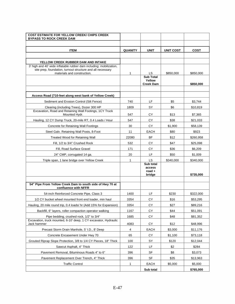
E-47
COST ESTIMATE FOR YELLOW CREEK/ CHIPS CREEK BYPASS TO ROCK CREEK DAM
ITEM QUANITY UNIT UNIT COST COST
YELLOW CREEK RUBBER DAM AND INTAKE 3' high and 40' wide inflatable rubber dam including: mobilization,
site prep, foundation, turnout structure and all necessary materials and construction. 1 LS $850,000 $850,000
Sub Total Yellow
Creek Dam $850,000
Access Road (710-feet along west bank of Yellow Creek)
Sediment and Erosion Control (Silt Fence) 740 LF $5 $3,744
Clearing (including Trees), Dozer 300 HP 1809 SY $6 $10,819 Excavation, Road and Retaining Wall Footings, 1CY Truck
Mounted Hydr. 547 CY $13 $7,365
Hauling, 12 CY Dump Truck, 20-mile RT, 0.4 Loads / Hour 547 CY $38 $21,033
Concrete for Retaining Wall Footings 30 CY $1,900 $58,139
Steel Galv. Retaining Wall Posts, 8-Foot 11 EACH $80 $923
Treated Wood for Retaining Wall 22080 BF $12 $260,958
Fill, 1/2 to 3/4" Crushed Rock 532 CY $47 $25,098
Fill, Road Surface Gravel 171 CY $36 $6,209
24" CMP, corrugated 14 ga. 20 LF $50 $1,009
Triple span, 1 lane bridge over Yellow Creek 1 LS $340,000 $340,000
Sub total access road + bridge $735,000
54" Pipe From Yellow Creek Dam to south side of Hwy 70 at
confluence with NFFR
54-inch Reinforced Concrete Pipe, Class 3 1400 LF $230 $322,000
1/2 CY bucket wheel mounted front end loader, min haul 3354 CY $16 $53,295
Hauling, 20 mile round trip, 0.4 loads/ hr (Add 15% for Expansion) 3354 CY $27 $89,216
Backfill, 6" layers, roller compaction operator walking 1167 CY $44 $51,091
Pipe bedding, crushed rock, 1/2" to 3/4" 1685 CY $48 $81,352 Excavation, truck mounted, 6-10' deep, 1 CY excavator, Hydraulic Jack hammer 4083 CY $12 $48,996
Precast Storm Drain Manhole, 5' I.D., 8' Deep 4 EACH $3,000 $11,176
Concrete Encasement Under Hwy 70 65 CY $1,100 $73,118
Grouted Riprap Slope Protection, 3/8 to 1/4 CY Pieces, 18" Thick 100 SY $120 $12,044
Sawcut Asphalt, 4" Thick 122 LF $2 $284
Pavement Removal, Bituminous Roads 4" to 6" 396 SF $8 $3,073
Pavement Replacement Over Trench, 4" Thick 396 SF $35 $13,963
Traffic Control 1 EACH $5,000 $5,000
Sub total $765,000

E-48
54" Pipe From south side of Hwy 70 at confluence with NFFR
to tie in at Chips Creek
Clearing, medium 1 ACRE $1,400 $1,400
54-inch Reinforced Concrete Pipe, Class 3 6913 LF $230 $1,589,990
1/2 CY bucket wheel mounted front end loader, min haul 16562 CY $16 $263,170
Hauling, 20 mile round trip, 0.4 loads/ hr (Add 15% for Expansion) 16562 CY $27 $440,549
Backfill, 6" layers, roller compaction operator walking 5761 CY $44 $252,217
Pipe bedding, crushed rock, 1/2" to 3/4" 8319 CY $48 $401,641 Excavation, truck mounted, 6-10' deep, 1 CY excavator, Hydraulic Jack hammer 20163 CY $12 $241,956
Remove Gravel shoulder 1874 SY $7 $12,481
Replace Gravel shoulder 625 CY $48 $30,175
Grouted Riprap Slope Protection, 3/8 to 1/4 CY Pieces, 18" Thick 9471 SY $120 $1,140,687
Sediment and Erosion Control (Silt Fence) 6913 LF $5 $34,980 Remove and reset existing corrugated metal guard rail (includes
all guard rail on 70) 12940 LF $35 $449,277
Precast Storm Drain Manhole, 5' I.D., 8' Deep 20 EACH $3,000 $60,000
Traffic control, signage (includes traffic cont. down to dam) 1 LS $30,000 $30,000
Traffic control, 2 signals (includes traffic cont. down to dam) 1 LS $380,000 $380,000
Sub total $5,329,000
CHIPS CREEK RUBBER DAM AND INTAKE 3' high and 40' wide inflatable rubber dam including: mobilization,
site prep, foundation, turnout structure and all necessary materials and construction. 1 LS $850,000 $850,000
Sub Total Chips
Creek Dam $850,000
Chips Creek Dam to tie in at Hwy 70
18-inch Reinforced Concrete Pipe, Class 3 740 LF $37 $27,698 Excavation, truck mounted, 6-10' deep, 1 CY excavator, Hydraulic
Jack hammer 925 CY $12 $11,100
1/2 CY bucket wheel mounted front end loader, min haul 638 CY $16 $10,138
Hauling, 20 mile round trip, 0.4 loads/ hr (Add 15% for Expansion) 638 CY $27 $16,971
Pipe bedding, crushed rock, 1/2" to 3/4" 420 CY $48 $20,278 Compaction, walk behind vibrating plate, 18" wide, 6" lifts, 4
passes 790 CY $3 $2,394
Precast Storm Drain Manhole, 5' I.D., 8' Deep 2 EACH $3,000 $6,000 Excavate and load on truck, bank measure. Bucket drag line 3/4
CY, sand & gravel 397 CY $4 $1,632 Temporary road, gravel fill, no surfacing, 6" gravel depth (10'
wide) 794 SY $11 $8,790 Hand grade select gravel, including compaction, 6" deep (10'
wide) 794 SY $3 $2,453
Concrete Encasement Under Hwy 70 39 CY $1,100 $43,871
Sawcut Asphalt, 4" Thick 80 LF $2 $186
Pavement Removal, Bituminous Roads 4" to 6" 240 SF $8 $1,862
Pavement Replacement Over Trench, 4" Thick 240 SF $35 $8,462
Traffic Control 1 EACH $5,000 $5,000

E-49
Tie in structure, 18" and 54" RCP in, 60" RCP out 1 LS $5,000 $5,000
Sub Total $172,000
Tie in at Hwy 70 to top of Rock Creek Dam
Clearing, medium 1 ACRE $1,400 $1,400
60-inch Reinforced Concrete Pipe, Class 3 7893 LF $279 $2,200,963 Excavation, truck mounted, 6-10' deep, 1 CY excavator, Hydraulic
Jack hammer 28576 CY $12 $342,912
1/2 CY bucket wheel mounted front end loader, min haul 24289 CY $16 $385,952
Backfill, 6" layers, roller compaction operator walking 7455 CY $44 $326,380
Pipe bedding, crushed rock, 1/2" to 3/4" 11421 CY $48 $551,406
Hauling, 20 mile round trip, 0.4 loads/ hr (Add 15% for Expansion) 24289 CY $27 $646,087
Precast Storm Drain Manhole, 6' I.D., 8' Deep 34 EACH $4,000 $136,000
Grouted Riprap Slope Protection, 3/8 to 1/4 CY Pieces, 18" Thick 11690 SY $120 $1,407,944
Remove Gravel shoulder 2140 SY $7 $14,252
Replace Gravel shoulder 713 CY $48 $34,424
Sediment and Erosion Control (Silt Fence) 7893 LF $5 $39,939
Sub Total $6,088,000
Top of Rock Creek Dam to Outlet
60" black steel pipe 155 LF $572 $88,660
Rock excavation, drill and blast 11 CY $128 $1,412
Drill rock anchor bolts 494 LF $29 $14,143
Install rock anchor bolts 480 LF $25 $12,154
Anchor rings 5 EACH $800 $4,000
Stair tower (Down to base of dam) 1 LS $224,000 224,000
66-inch hydraulic operated butterfly valve 1 LS $66,000 $66,000
Sub total $410,000
Indian Creek Crossing Cast in place 10.5'W x 1.5'H x 16'L Reinforced Concrete Box
Culvert 8 CY $2,770 $22,160
Cast in place culvert transitions to 54" pipe 3 CY $2,770 $8,310
Structural excavation 84 CY $46 $3,864
1/2 CY bucket wheel mounted front end loader, min haul 97 CY $16 $1,541
Hauling, 20 mile round trip, 0.4 loads/ hr (Add 15% for Expansion) 97 CY $27 $2,580
Backfill and roller compaction operator walking 9 CY $44 $394
Remove Gravel shoulder 6 SY $7 $40
Replace Gravel shoulder 2 CY $48 $97
Bedding, crushed rock, 1/2" to 3/4" 7 CY $49 $345
Clearing 1 LS $500 $500
Grouted Riprap Slope Protection, 3/8 to 1/4 CY Pieces, 18" Thick 28 SY $120 $3,372
Sub total $43,000

E-50
Various Small Culverts (3) Upstream of Chips Tie-In Cast in place 10.5'W x 1.5'H x 6'L Reinforced Concrete Box
Culverts 9 CY $2,770 $24,930
Cast in place culvert transitions to pipe 9 CY $2,770 $24,930
Structural excavation 148 CY $46 $6,808
1/2 CY bucket wheel mounted front end loader, min haul 170 CY $16 $2,701
Hauling, 20 mile round trip, 0.4 loads/ hr (Add 15% for Expansion) 170 CY $27 $4,522
Backfill and roller compaction operator walking 16 CY $44 $700
Remove Gravel shoulder 11.5 SY $7 $77
Replace Gravel shoulder 4 CY $48 $193
Bedding, crushed rock, 1/2" to 3/4" 12 CY $49 $591
Clearing 1 LS $1,500 $1,500
Grouted Riprap Slope Protection, 3/8 to 1/4 CY Pieces, 18" Thick 47.8 SY $120 $5,757
Sub total $73,000
Chips Creek Crossing
60" black steel pipe 130 LF $572 $74,360
Concrete pier footing, piers, pier caps and abutments 19 CY $1,800 $33,558
Pier and abutment excavation 18 CY $46 $828
Structural steel 12 TONS $3,200 $38,400
Structural steel, pier supports 3 TONS $4,300 $12,900
Steel, anchor rings 5 EACH $800 $4,000
Sediment and Erosion Control (Silt Fence) 130 LF $5 $658
Clearing 1 LS $500 $500 Excavation, truck mounted, 6-10' deep, 1 CY excavator, Hydraulic
Jack hammer 43 CY $12 $516
Backfill, 6" layers, roller compaction operator walking 18 CY $44 $788
Grouted Riprap Slope Protection, 3/8 to 1/4 CY Pieces, 18" Thick 18 SY $120 $2,168
Hauling, 20 mile round trip, 0.4 loads/ hr (Add 15% for Expansion) 38 CY $27 $1,011
Remove Gravel shoulder 3 SY $7 $20
Replace Gravel shoulder 1 CY $48 $48
Bedding, crushed rock, 1/2" to 3/4" 17 CY $48 $821
Sub total $171,000
Paul's and Murphy's Creek Crossing (downstream of Chips
Creek Tie-In) Cast in place 13'W x 1.5'H x 9'L Reinforced Concrete Box
Culverts 11 CY $2,770 $30,470
Cast in place culvert transitions to pipe 7 CY $2,770 $19,390
Structural excavation 149 CY $46 $6,854
1/2 CY bucket wheel mounted front end loader, min haul 171 CY $16 $2,717
Hauling, 20 mile round trip, 0.4 loads/ hr (Add 15% for Expansion) 171 CY $27 $4,549
Backfill and roller compaction operator walking 15 CY $44 $657
Remove Gravel shoulder 9 SY $7 $60
Replace Gravel shoulder 3 CY $48 $145
Bedding, crushed rock, 1/2" to 3/4" 12 CY $48 $579

E-51
Clearing 1 LS $1,000 $1,000
Grouted Riprap Slope Protection, 3/8 to 1/4 CY Pieces, 18" Thick 39 SY $120 $4,697
Sub total $71,000
Various Small Culverts (2) Downstream of Chips Tie-In Cast in place 13'W x 1.5'H x 6'L Reinforced Concrete Box
Culverts 7.4 CY $2,770 $20,498
Cast in place culvert transitions to pipe 7.4 CY $2,770 $20,498
Structural excavation 122 CY $46 $5,612
1/2 CY bucket wheel mounted front end loader, min haul 140 CY $16 $2,225
Hauling, 20 mile round trip, 0.4 loads/ hr (Add 15% for Expansion) 140 CY $27 $3,724
Backfill and roller compaction operator walking 13 CY $44 $569
Remove Gravel shoulder 8 SY $7 $53
Replace Gravel shoulder 3 CY $48 $145
Bedding, crushed rock, 1/2" to 3/4" 10 CY $49 $493
Clearing 1 LS $1,500 $1,500
Grouted Riprap Slope Protection, 3/8 to 1/4 CY Pieces, 18" Thick 32 SY $120 $3,854
Sub total $59,000
Mobilization / Demobilization
Dozer, above 150 HP (3) 1 LS $3,600 $3,600
Excavator, 1-1.5 CY Diesel Hyd. (2) 1 LS $9,600 $9,600
Loader (2) 1 LS $2,400 $2,400
Dump truck, 26 tons (10) 1 LS $6,000 $6,000
25 ton truck mounted hydraulic crane (2) 1 LS $2,000 $2,000
Crawler Type Drill, 4" (1) 1 LS $700 $700
Grader, 30,000 lbs (2) 1 LS $2,400 $2,400
Grout pumper (1) 1 LS $600 $600
Water truck, 6000 gal (2) 1 LS $1,200 $1,200
Wash & Screen (1) 1 LS $7,200 $7,200
Sub total $36,000
Total $15,652,000
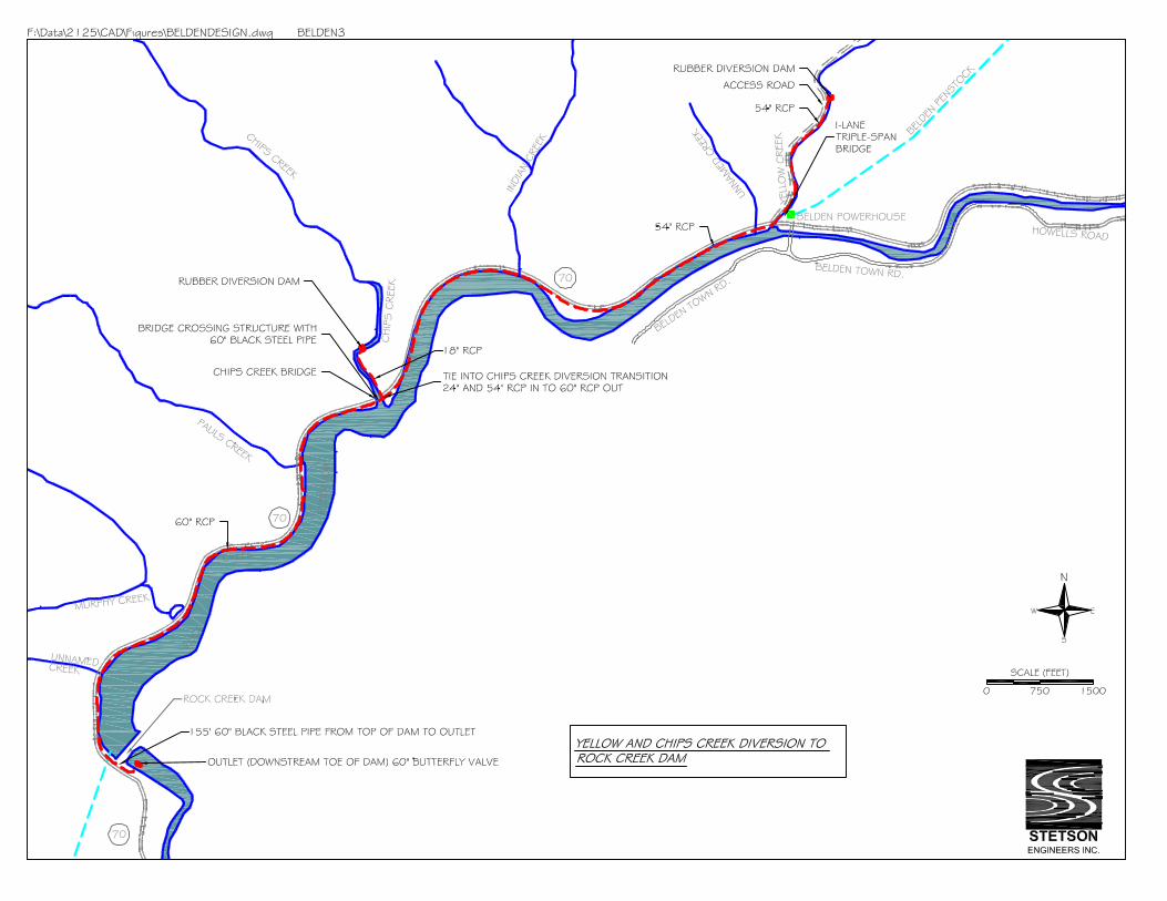

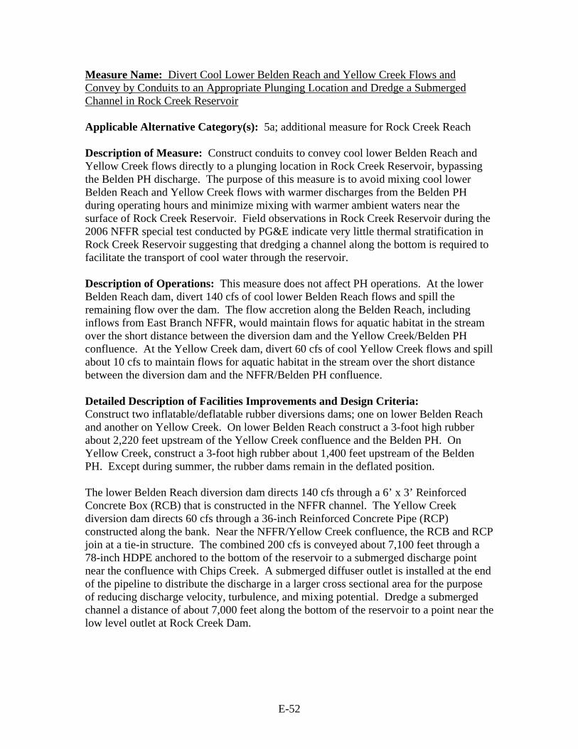
E-52
Measure Name: Divert Cool Lower Belden Reach and Yellow Creek Flows and Convey by Conduits to an Appropriate Plunging Location and Dredge a Submerged Channel in Rock Creek Reservoir Applicable Alternative Category(s): 5a; additional measure for Rock Creek Reach Description of Measure: Construct conduits to convey cool lower Belden Reach and Yellow Creek flows directly to a plunging location in Rock Creek Reservoir, bypassing the Belden PH discharge. The purpose of this measure is to avoid mixing cool lower Belden Reach and Yellow Creek flows with warmer discharges from the Belden PH during operating hours and minimize mixing with warmer ambient waters near the surface of Rock Creek Reservoir. Field observations in Rock Creek Reservoir during the 2006 NFFR special test conducted by PG&E indicate very little thermal stratification in Rock Creek Reservoir suggesting that dredging a channel along the bottom is required to facilitate the transport of cool water through the reservoir. Description of Operations: This measure does not affect PH operations. At the lower Belden Reach dam, divert 140 cfs of cool lower Belden Reach flows and spill the remaining flow over the dam. The flow accretion along the Belden Reach, including inflows from East Branch NFFR, would maintain flows for aquatic habitat in the stream over the short distance between the diversion dam and the Yellow Creek/Belden PH confluence. At the Yellow Creek dam, divert 60 cfs of cool Yellow Creek flows and spill about 10 cfs to maintain flows for aquatic habitat in the stream over the short distance between the diversion dam and the NFFR/Belden PH confluence. Detailed Description of Facilities Improvements and Design Criteria: Construct two inflatable/deflatable rubber diversions dams; one on lower Belden Reach and another on Yellow Creek. On lower Belden Reach construct a 3-foot high rubber about 2,220 feet upstream of the Yellow Creek confluence and the Belden PH. On Yellow Creek, construct a 3-foot high rubber about 1,400 feet upstream of the Belden PH. Except during summer, the rubber dams remain in the deflated position. The lower Belden Reach diversion dam directs 140 cfs through a 6’ x 3’ Reinforced Concrete Box (RCB) that is constructed in the NFFR channel. The Yellow Creek diversion dam directs 60 cfs through a 36-inch Reinforced Concrete Pipe (RCP) constructed along the bank. Near the NFFR/Yellow Creek confluence, the RCB and RCP join at a tie-in structure. The combined 200 cfs is conveyed about 7,100 feet through a 78-inch HDPE anchored to the bottom of the reservoir to a submerged discharge point near the confluence with Chips Creek. A submerged diffuser outlet is installed at the end of the pipeline to distribute the discharge in a larger cross sectional area for the purpose of reducing discharge velocity, turbulence, and mixing potential. Dredge a submerged channel a distance of about 7,000 feet along the bottom of the reservoir to a point near the low level outlet at Rock Creek Dam.

E-53
List of Figures:
• Plan view: Yellow Creek and Lower Belden Reach (NFFR) to Rock Creek Reservoir Plunging
• Profile: Yellow Creek / Belden Reach (NFFR) to Rock Creek Reservoir Plunging Key Design or Construction Uncertainties Requiring Further Study:
• Dredging the reservoir bottom may require removing large boulders which could be difficult and costly.
• The dredged conveyance channel at the bottom of Rock Creek Reservoir will likely fill with sediment and will require repeated dredging.
• The effectiveness of cold water transport by a dredged channel in Rock Creek Reservoir requires further study.
• Setting a 78-inch HDPE along the bottom of Rock Creek Reservoir will be difficult and costly. Design and installation of an anchoring system adequate to withstand the potential forces on the pipe arising from flow momentum and land shifting requires further study.
• Installing a 6’ x 3’ reinforced concrete box culvert inside the channel along the north bank of the NFFR will be difficult and costly due to boulders and water in the channel.
Discussion: The location of the lower Belden Reach dam assumes that the measure to divert and convey warm East Branch NFFR flows to upper Rock Creek Reservoir is implemented. If it is not implemented, then the lower Belden Reach diversion dam needs to be located above the confluence of East Branch NFFR.

E-54
COST ESTIMATE FOR LOWER BELDEN REACH / YELLOW CREEK BYPASS TO PLUNGING
ITEM QUANITY UNIT UNIT COST COST
YELLOW CREEK RUBBER DAM AND
INTAKE 3' high and 71' wide inflatable rubber dam
including: mobilization, site prep, foundation, turnout structure and all necessary materials
and construction. 1 LS $1,510,000 $1,510,000
Sub Total Yellow Creek Dam $1,510,000
N FORK FEATHER RIVER RUBBER DAM
AND INTAKE
Mobilization
Mobilization 1 LS $9,700 $9,700
Site Clearing and Excavation
Site Clearing 1 LS $1,200 $1,200
Excavation Inside Channel 150 CY $24 $3,532
Rubber Diversion Dam
Concrete for Foundation 50 CY $1,200 $60,000
Anchor Bolts 1 LS $1,200 $1,200
Rubber Dam with Controls (3-foot diameter) 1 LS $259,000 $259,000
Installation of Rubber Dam and Controls 1 LS $24,000 $24,000 Installation Advisor for Rubber Dam and
Controls 1 LS $12,000 $12,000
Turnout Structure
Excavation 300 CY $24 $7,065
Concrete 40 CY $1,800 $72,000
6'W X 3'H Canal Control Gate 1 LS $5,000 $5,000
Handrail 1 LS $600 $600
8-inch Diameter Vent Pipe, HDPE 1 LS $400 $400
Access Hatch 1 LS $600 $600
Precast Concrete Steps 1 LS $600 $600
Trash Rack 1 LS $5,900 $5,900
Cleanup and Demobilization
Cleanup and Demobilization 1 LS $9,700 $9,700
Sub Total NF Feather River
Dam $472,000
Access Road (710-feet along west bank of
Yellow Creek)

E-55
Sediment and Erosion Control (Silt Fence) 740 LF $5 $3,744
Clearing (including Trees), Dozer 300 HP 1809 SY $6 $10,819 Excavation, Road and Retaining Wall Footings, 1CY Truck Mounted Hydr. 547 CY $13 $7,365
Hauling, 12 CY Dump Truck, 20-mile RT, 0.4 Loads / Hour 547 CY $38 $21,033
Concrete for Retaining Wall Footings 30 CY $1,900 $57,000
Steel Galv. Retaining Wall Posts, 8-Foot 11 EACH $84 $923
Treated Wood for Retaining Wall 22080 BF $12 $260,958
Fill, 1/2 to 3/4" Crushed Rock 532 CY $47 $25,098
Fill, Road Surface Gravel 171 CY $36 $6,209
24" CMP, corrugated 14 ga. 20 LF $50 $1,009
Triple span, 1 lane bridge over Yellow Creek 1 LS $344,000 $344,000
Sub total access road $738,000
36" Pipe From Dam to Tie In at
Confluence of Yellow Creek and NF Feather River
36-inch Reinforced Concrete Pipe, Class 3 1370 LF $104 $142,699 1/2 CY bucket wheel mounted front end
loader, min haul 2566 CY $16 $40,774 Hauling, 20 mile round trip, 0.4 loads/ hr (Add
15% for Expansion) 2566 CY $27 $68,256 Compaction, walk behind vibrating plate, 18"
wide, 6" lifts, 4 passes 1541 CY $3 $4,669
Pipe bedding, crushed rock, 1/2" to 3/4" 1541 CY $48 $74,399 Excavation, truck mounted, 6-10' deep, 1 CY excavator, Hydraulic Jack hammer 2231 CY $12 $26,772
Precast Storm Drain Manhole, 4' I.D., 8' Deep 4 EACH $1,900 $7,600
Concrete Encasement Under Hwy 70 43 CY $1,125 $48,370 Grouted Riprap Slope Protection, 3/8 to 1/4
CY Pieces, 18" Thick 100 SY $120 $12,044 Tie in Structure (36"RCP & 6'x3' RCB in / 78"
HDPE out) 1 LS $6,000 $6,000
Sawcut Asphalt, 4" Thick 122 LF $2 $284 Pavement Removal, Bituminous Roads 4" to
6" 396 SF $8 $3,073 Pavement Replacement Over Trench, 4"
Thick 396 SF $35 $13,963
Traffic Control 1 EACH $5,000 $5,000
Sub total 36" pipe $454,000
6' x 3' RCB From NF Feather River Dam to
Tie In
6' x 3' Reinforced Concrete Box 2222 LF $347 $771,478 1/2 CY bucket wheel mounted front end
loader, min haul 3408 CY $16 $54,153 Hauling, 20 mile round trip, 0.4 loads/ hr (Add
15% for Expansion) 3408 CY $27 $90,653 Excavator, Clamshell, 1/2 CY, wet plus addit.
Equip 2963 CY $26 $75,942
Sub total 6' x 3' RCB $992,000
78-Inch HDPE From Tie In to Chips Creek
(With Dredging to Dam)

E-56
78-Inch HDPE From Tie In to Chips Creek 7100 LF $500 $3,550,000 HDPE Pipe Placement, S-lay method with stinger, Mechanical Crane, barge mounted 1 LS $1,700,000 $1,700,000
Mechanical Dredging, barge mounted, clamshell, hopper dumped 130256 CY $13 $1,667,277
Cofferdam, 15-22' Deep, 2 lines of braces, 10" H max 117200 SF $39 $4,570,800
Furnish and place topsoil, truck dumped, screened, 4" deep 39067 SY $4 $151,580
Fine grading with seeding inc lime, fertilizer & seed w/ equip. 351600 SF $6 $2,271,336
Concrete Outlet Diffuser Structure, Structure Pad and Rock Cover 1 LS $15,000 $15,000
Sub total 7' x 4' RCB $13,926,000
Mobilization
Dozer, above 150 HP (3) 1 LS $3,600 $3,600
Excavator, 1-1.5 CY Diesel Hyd. (2) 1 LS $9,600 $9,600
Loader (2) 1 LS $2,400 $2,400
Paver Mobilization 1 LS $1,200 $1,200
Grout pumper (1) 1 LS $600 $600 Mechanical Dredger, Crane and stinger,
barge mounted and all equipment 1 LS $200,000 $200,000
Sub total Mob / Demob $217,000
TOTAL $18,309,000
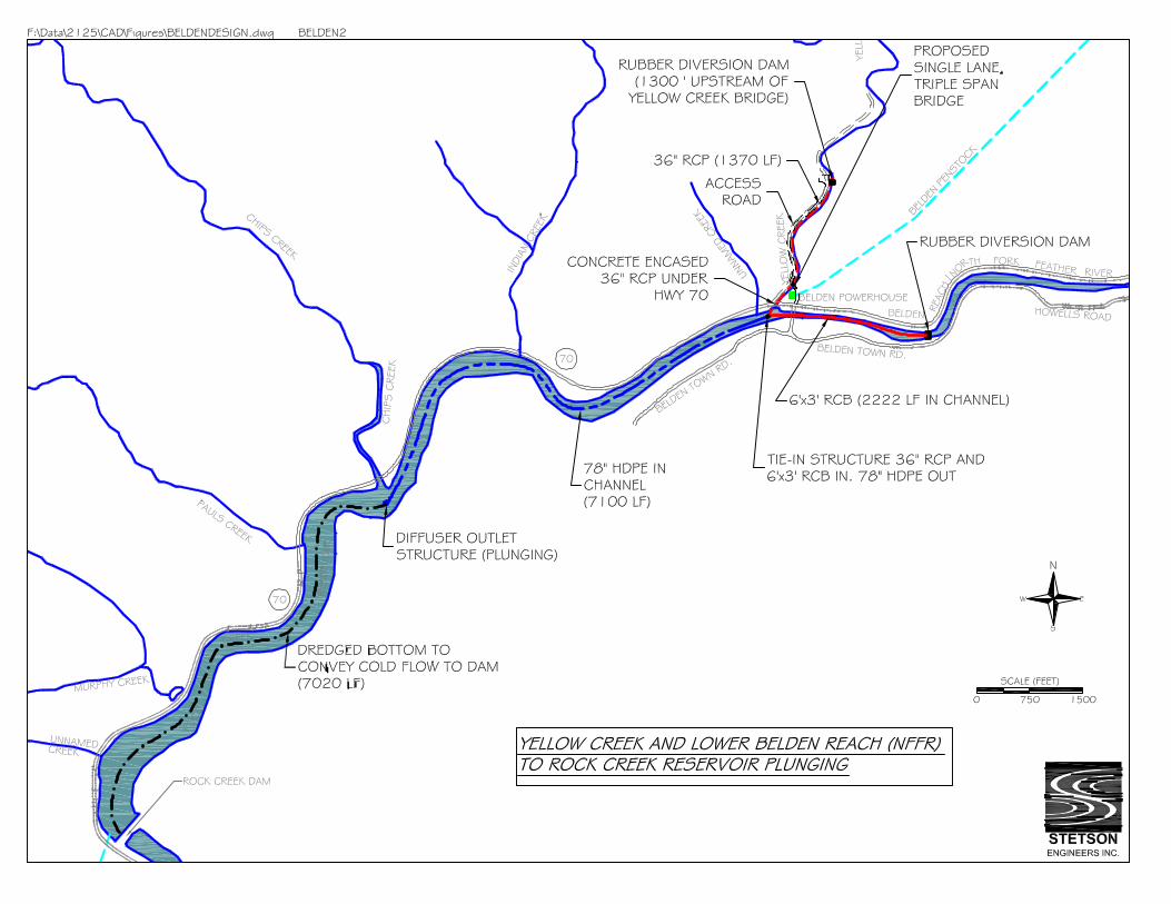

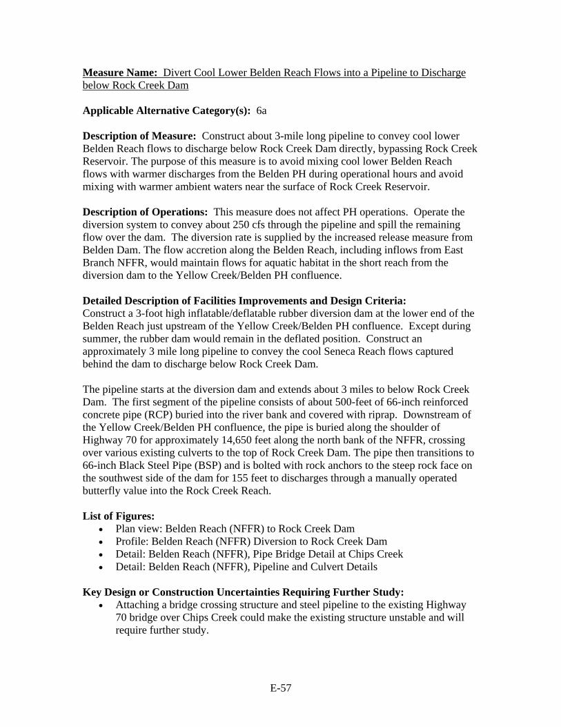
E-57
Measure Name: Divert Cool Lower Belden Reach Flows into a Pipeline to Discharge below Rock Creek Dam Applicable Alternative Category(s): 6a Description of Measure: Construct about 3-mile long pipeline to convey cool lower Belden Reach flows to discharge below Rock Creek Dam directly, bypassing Rock Creek Reservoir. The purpose of this measure is to avoid mixing cool lower Belden Reach flows with warmer discharges from the Belden PH during operational hours and avoid mixing with warmer ambient waters near the surface of Rock Creek Reservoir. Description of Operations: This measure does not affect PH operations. Operate the diversion system to convey about 250 cfs through the pipeline and spill the remaining flow over the dam. The diversion rate is supplied by the increased release measure from Belden Dam. The flow accretion along the Belden Reach, including inflows from East Branch NFFR, would maintain flows for aquatic habitat in the short reach from the diversion dam to the Yellow Creek/Belden PH confluence. Detailed Description of Facilities Improvements and Design Criteria: Construct a 3-foot high inflatable/deflatable rubber diversion dam at the lower end of the Belden Reach just upstream of the Yellow Creek/Belden PH confluence. Except during summer, the rubber dam would remain in the deflated position. Construct an approximately 3 mile long pipeline to convey the cool Seneca Reach flows captured behind the dam to discharge below Rock Creek Dam. The pipeline starts at the diversion dam and extends about 3 miles to below Rock Creek Dam. The first segment of the pipeline consists of about 500-feet of 66-inch reinforced concrete pipe (RCP) buried into the river bank and covered with riprap. Downstream of the Yellow Creek/Belden PH confluence, the pipe is buried along the shoulder of Highway 70 for approximately 14,650 feet along the north bank of the NFFR, crossing over various existing culverts to the top of Rock Creek Dam. The pipe then transitions to 66-inch Black Steel Pipe (BSP) and is bolted with rock anchors to the steep rock face on the southwest side of the dam for 155 feet to discharges through a manually operated butterfly value into the Rock Creek Reach. List of Figures:
• Plan view: Belden Reach (NFFR) to Rock Creek Dam • Profile: Belden Reach (NFFR) Diversion to Rock Creek Dam • Detail: Belden Reach (NFFR), Pipe Bridge Detail at Chips Creek • Detail: Belden Reach (NFFR), Pipeline and Culvert Details
Key Design or Construction Uncertainties Requiring Further Study:
• Attaching a bridge crossing structure and steel pipeline to the existing Highway 70 bridge over Chips Creek could make the existing structure unstable and will require further study.

E-58
• Burying a 66-inch Reinforced Concrete Pipe near the channel along the north bank of the NFFR just upstream of the confluence with Yellow Creek will be difficult and costly due to boulders and water in the channel.
• Connecting 155 LF of 66-inch Black Steel Pipe to the steep rock face at the dam requires further study.
Discussion: The location of the lower Belden Reach dam assumes that the measure to divert and convey warm East Branch NFFR flows into upper Rock Creek Reservoir is implemented. If it is not implemented, then the lower Belden Reach diversion dam needs to be located above the confluence of East Branch NFFR.
COST ESTIMATE FOR LOWER BELDEN REACH BYPASS TO ROCK CREEK DAM
OPTION A 250 CFS
ITEM QUANITY UNIT UNIT COST COST
N FORK FEATHER RIVER RUBBER DAM AND INTAKE (Rounded) 3' high and 71' wide inflatable rubber dam including:
mobilization, site prep, foundation, turnout structure and all necessary materials and construction. 1 LS $1,510,000 $1,510,000
Sub Total $1,510,000
66" Pipe From Dam to north bank of NF Feather River,
66-inch Reinforced Concrete Pipe, Class 3 500 LF 309 $154,500
Excavator, Clamshell, 1/2 CY, wet plus addit. Equip 1811 CY 26 $46,416
1/2 CY bucket wheel mounted front end loader, min haul 2083 CY 16 $33,099 Hauling, 20 mile round trip, 0.4 loads/ hr (Add 15% for
Expansion) 2083 CY 27 $55,408
Pipe bedding, crushed rock, 1/2" to 3/4" 723 CY 48 $34,906
Backfill, 6" layers, roller compaction operator walking 472 CY 44 $20,664 Grouted Riprap Slope Protection, 3/8 to 1/4 CY Pieces, 18"
Thick 16 SY 120 $1,927
Sediment and Erosion Control (Silt Fence) 500 LF 5 $2,530
Precast Storm Drain Manhole, 6' I.D., 8' Deep 1 EACH 4,300 $4,300
Sub Total $354,000
66" Pipe from north bank of NF Feather River to SW side of
Rock Creek Dam
66-inch Reinforced Concrete Pipe, Class 3 14654 LF 309 $4,528,086
Clearing, medium 2 ACRE 1,400 $2,800
Backfill, 6" layers, roller compaction operator walking 13593 CY 44 $595,102
Pipe bedding, crushed rock, 1/2" to 3/4" 20826 CY 48 $1,005,479 Excavation, truck mounted, 6-10' deep, 1 CY excavator,
Hydraulic Jack hammer 52108 CY 12 $625,296
1/2 CY bucket wheel mounted front end loader, min haul 44292 CY 16 $703,800
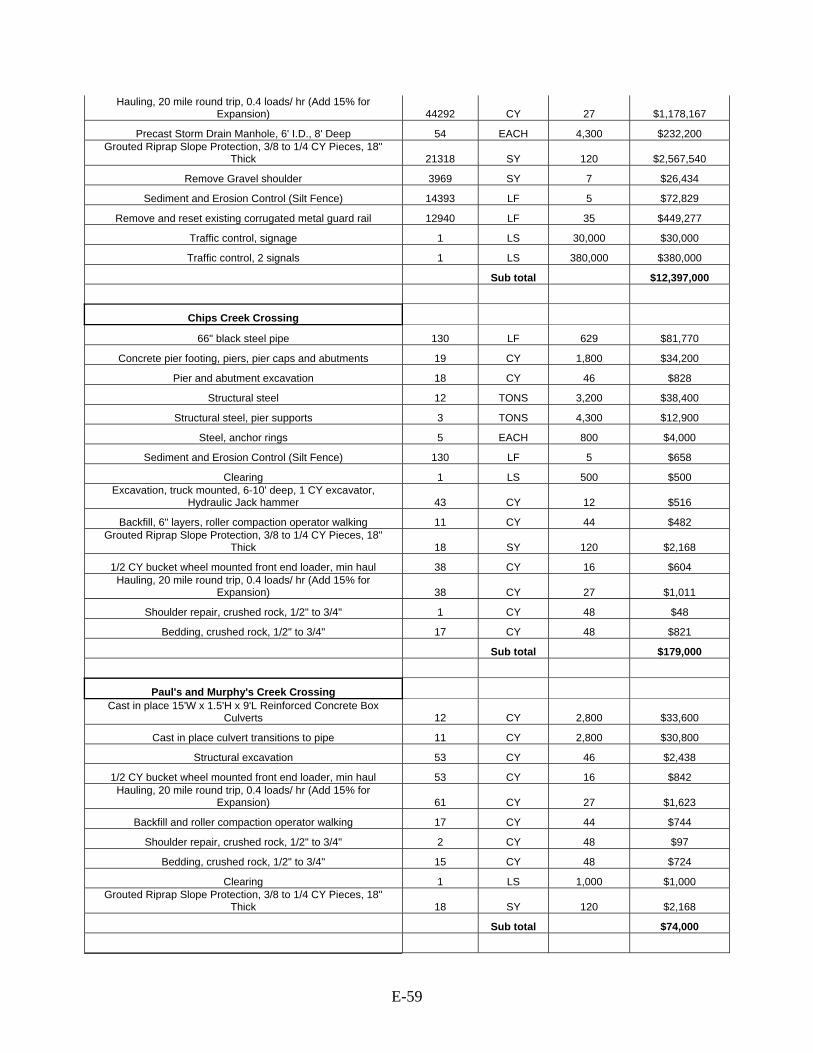
E-59
Hauling, 20 mile round trip, 0.4 loads/ hr (Add 15% for Expansion) 44292 CY 27 $1,178,167
Precast Storm Drain Manhole, 6' I.D., 8' Deep 54 EACH 4,300 $232,200 Grouted Riprap Slope Protection, 3/8 to 1/4 CY Pieces, 18"
Thick 21318 SY 120 $2,567,540
Remove Gravel shoulder 3969 SY 7 $26,434
Sediment and Erosion Control (Silt Fence) 14393 LF 5 $72,829
Remove and reset existing corrugated metal guard rail 12940 LF 35 $449,277
Traffic control, signage 1 LS 30,000 $30,000
Traffic control, 2 signals 1 LS 380,000 $380,000
Sub total $12,397,000
Chips Creek Crossing
66" black steel pipe 130 LF 629 $81,770
Concrete pier footing, piers, pier caps and abutments 19 CY 1,800 $34,200
Pier and abutment excavation 18 CY 46 $828
Structural steel 12 TONS 3,200 $38,400
Structural steel, pier supports 3 TONS 4,300 $12,900
Steel, anchor rings 5 EACH 800 $4,000
Sediment and Erosion Control (Silt Fence) 130 LF 5 $658
Clearing 1 LS 500 $500 Excavation, truck mounted, 6-10' deep, 1 CY excavator,
Hydraulic Jack hammer 43 CY 12 $516
Backfill, 6" layers, roller compaction operator walking 11 CY 44 $482 Grouted Riprap Slope Protection, 3/8 to 1/4 CY Pieces, 18"
Thick 18 SY 120 $2,168
1/2 CY bucket wheel mounted front end loader, min haul 38 CY 16 $604 Hauling, 20 mile round trip, 0.4 loads/ hr (Add 15% for
Expansion) 38 CY 27 $1,011
Shoulder repair, crushed rock, 1/2" to 3/4" 1 CY 48 $48
Bedding, crushed rock, 1/2" to 3/4" 17 CY 48 $821
Sub total $179,000
Paul's and Murphy's Creek Crossing Cast in place 15'W x 1.5'H x 9'L Reinforced Concrete Box
Culverts 12 CY 2,800 $33,600
Cast in place culvert transitions to pipe 11 CY 2,800 $30,800
Structural excavation 53 CY 46 $2,438
1/2 CY bucket wheel mounted front end loader, min haul 53 CY 16 $842 Hauling, 20 mile round trip, 0.4 loads/ hr (Add 15% for
Expansion) 61 CY 27 $1,623
Backfill and roller compaction operator walking 17 CY 44 $744
Shoulder repair, crushed rock, 1/2" to 3/4" 2 CY 48 $97
Bedding, crushed rock, 1/2" to 3/4" 15 CY 48 $724
Clearing 1 LS 1,000 $1,000 Grouted Riprap Slope Protection, 3/8 to 1/4 CY Pieces, 18"
Thick 18 SY 120 $2,168
Sub total $74,000

E-60
Indian Creek Crossing Cast in place 15'W x 1.5'H x 16'L Reinforced Concrete Box
Culvert 10 CY 2,800 $28,000
Cast in place culvert transitions to pipe 5 CY 2,800 $14,000
Structural excavation 37 CY 46 $1,702
1/2 CY bucket wheel mounted front end loader, min haul 43 CY 16 $683 Hauling, 20 mile round trip, 0.4 loads/ hr (Add 15% for
Expansion) 43 CY 27 $1,144
Backfill and roller compaction operator walking 14 CY 44 $613
Shoulder repair, crushed rock, 1/2" to 3/4" 1 CY 48 $48
Bedding, crushed rock, 1/2" to 3/4" 13 CY 49 $641
Clearing 1 LS 500 $500 Grouted Riprap Slope Protection, 3/8 to 1/4 CY Pieces, 18"
Thick 18 SY 120 $2,168
Sub total $50,000
Various Small Culverts (5) Cast in place 15'W x 1.5'H x 6'L Reinforced Concrete Box
Culverts 20 CY 2,800 $56,000
Cast in place culvert transitions to pipe 25 CY 2,800 $70,000
Structural excavation 109 CY 46 $5,014
1/2 CY bucket wheel mounted front end loader, min haul 125 CY 16 $1,986 Hauling, 20 mile round trip, 0.4 loads/ hr (Add 15% for
Expansion) 125 CY 27 $3,325
Backfill and roller compaction operator walking 32 CY 44 $1,401
Shoulder repair, crushed rock, 1/2" to 3/4" 5 CY 48 $241
Bedding, crushed rock, 1/2" to 3/4" 27 CY 49 $1,331
Clearing 1 LS 2,500 $2,500 Grouted Riprap Slope Protection, 3/8 to 1/4 CY Pieces, 18"
Thick 34 SY 120 $4,095
Sub total $146,000
Top of Rock Creek Dam to Outlet
66-inch Reinforced Concrete Pipe, Class 3 139 LF 309 $42,951
66" black steel pipe 155 LF 629 $97,495
Backfill, 6" layers, roller compaction operator walking 131 CY 44 $5,735
Pipe bedding, crushed rock, 1/2" to 3/4" 201 CY 48 $9,704 Excavation, truck mounted, 6-10' deep, 1 CY excavator,
Hydraulic Jack hammer 503 CY 12 $6,036 Hauling, 20 mile round trip, 0.4 loads/ hr (Add 15% for
Expansion) 460 CY 27 $12,236
Rock excavation, drill and blast 11 CY 128 $1,412
Drill rock anchor bolts 494 LF 29 $14,143
Install rock anchor bolts 480 LF 25 $12,154
Anchor rings 5 EACH 805 $4,025
Stair tower (Down to base of dam) 1 LS 224,000 224,000
66-inch hydraulic operated butterfly valve 1 LS 66,000 $66,000
Sub total $496,000
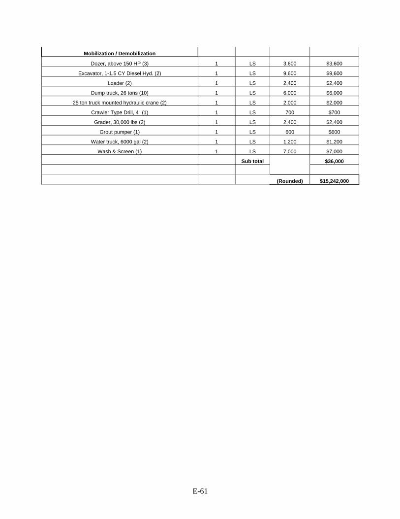
E-61
Mobilization / Demobilization
Dozer, above 150 HP (3) 1 LS 3,600 $3,600
Excavator, 1-1.5 CY Diesel Hyd. (2) 1 LS 9,600 $9,600
Loader (2) 1 LS 2,400 $2,400
Dump truck, 26 tons (10) 1 LS 6,000 $6,000
25 ton truck mounted hydraulic crane (2) 1 LS 2,000 $2,000
Crawler Type Drill, 4" (1) 1 LS 700 $700
Grader, 30,000 lbs (2) 1 LS 2,400 $2,400
Grout pumper (1) 1 LS 600 $600
Water truck, 6000 gal (2) 1 LS 1,200 $1,200
Wash & Screen (1) 1 LS 7,000 $7,000
Sub total $36,000
(Rounded) $15,242,000
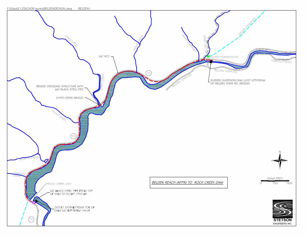
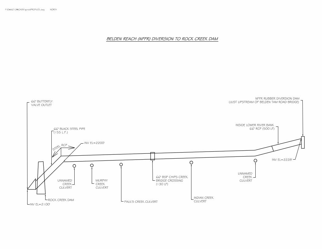


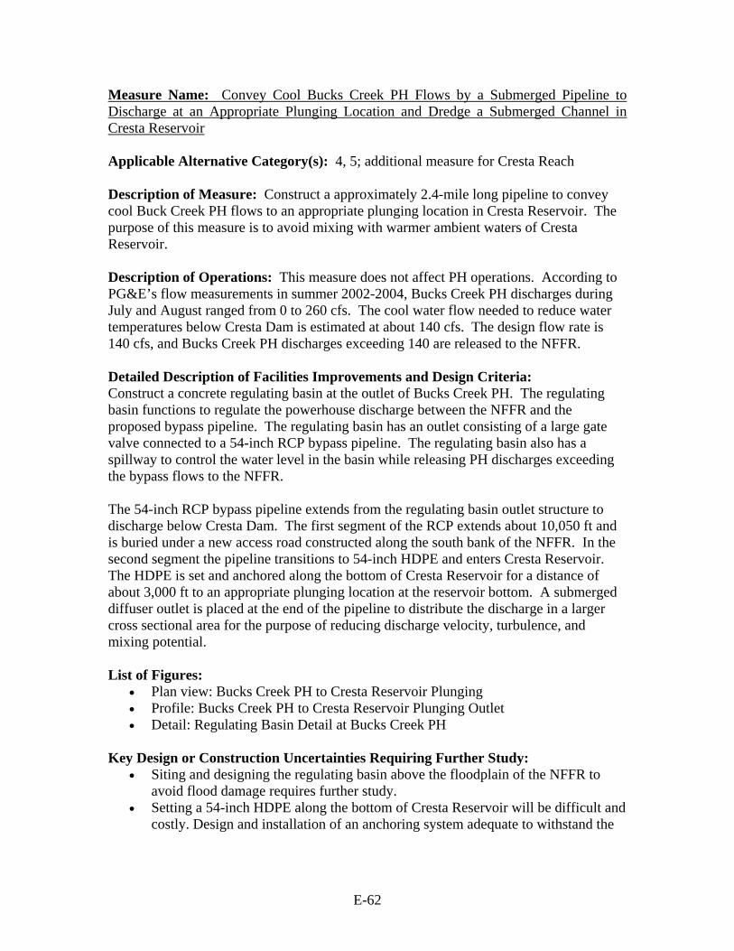
E-62
Measure Name: Convey Cool Bucks Creek PH Flows by a Submerged Pipeline to Discharge at an Appropriate Plunging Location and Dredge a Submerged Channel in Cresta Reservoir Applicable Alternative Category(s): 4, 5; additional measure for Cresta Reach Description of Measure: Construct a approximately 2.4-mile long pipeline to convey cool Buck Creek PH flows to an appropriate plunging location in Cresta Reservoir. The purpose of this measure is to avoid mixing with warmer ambient waters of Cresta Reservoir. Description of Operations: This measure does not affect PH operations. According to PG&E’s flow measurements in summer 2002-2004, Bucks Creek PH discharges during July and August ranged from 0 to 260 cfs. The cool water flow needed to reduce water temperatures below Cresta Dam is estimated at about 140 cfs. The design flow rate is 140 cfs, and Bucks Creek PH discharges exceeding 140 are released to the NFFR. Detailed Description of Facilities Improvements and Design Criteria: Construct a concrete regulating basin at the outlet of Bucks Creek PH. The regulating basin functions to regulate the powerhouse discharge between the NFFR and the proposed bypass pipeline. The regulating basin has an outlet consisting of a large gate valve connected to a 54-inch RCP bypass pipeline. The regulating basin also has a spillway to control the water level in the basin while releasing PH discharges exceeding the bypass flows to the NFFR. The 54-inch RCP bypass pipeline extends from the regulating basin outlet structure to discharge below Cresta Dam. The first segment of the RCP extends about 10,050 ft and is buried under a new access road constructed along the south bank of the NFFR. In the second segment the pipeline transitions to 54-inch HDPE and enters Cresta Reservoir. The HDPE is set and anchored along the bottom of Cresta Reservoir for a distance of about 3,000 ft to an appropriate plunging location at the reservoir bottom. A submerged diffuser outlet is placed at the end of the pipeline to distribute the discharge in a larger cross sectional area for the purpose of reducing discharge velocity, turbulence, and mixing potential. List of Figures:
• Plan view: Bucks Creek PH to Cresta Reservoir Plunging • Profile: Bucks Creek PH to Cresta Reservoir Plunging Outlet • Detail: Regulating Basin Detail at Bucks Creek PH
Key Design or Construction Uncertainties Requiring Further Study:
• Siting and designing the regulating basin above the floodplain of the NFFR to avoid flood damage requires further study.
• Setting a 54-inch HDPE along the bottom of Cresta Reservoir will be difficult and costly. Design and installation of an anchoring system adequate to withstand the
E-63
potential forces on the pipe arising from flow momentum and land shifting requires further study.
• Microtunneling a 42-inch diameter outlet tunnel through the toe of Cresta Dam will be difficult, costly and time consuming due to the thickness of the concrete at the toe of the dam.
• Dredging the reservoir bottom may require removing large boulders which could be difficult and costly.
• The dredged conveyance channel at the bottom of Cresta Reservoir will likely fill with sediment and will require repeated dredging.
• The effectiveness of cold water transport by a dredged channel in Cresta Reservoir requires further study.
Discussion: The required cool water flow of 140 cfs from Bucks Creek PH was estimated based on the assumption that the mixing ratio of ambient warm water is 50%.

E-64
COST ESTIMATE FOR BUCKS CREEK PH TO CRESTA RESERVOIR PLUNGING
ITEM QUANITY UNIT UNIT COST COST
Access Road (10,045-feet along south bank
of NFFR)
Sediment and Erosion Control (Silt Fence) 10045 LF $5 $50,817
Clearing (including Trees), Dozer 300 HP 24556 SY $6 $146,862 Excavation, Road and Retaining Wall Footings,
1CY Truck Mounted Hydr. 7425 CY $13 $99,976 Hauling, 12 CY Dump Truck, 20-mile RT, 0.4
Loads / Hour 7425 CY $38 $285,507
Concrete for Retaining Wall Footings 407 CY $1,900 $773,300
Concrete for Culvert Headwall Structures (6) 16 CY $1,900 $30,400
Steel Galv. Retaining Wall Posts, 8-Foot 152 EACH $84 $12,760
Treated Wood for Retaining Wall 299721 BF $12 $3,542,332
Fill, 1/2 to 3/4" Crushed Rock 7222 CY $47 $340,707
Fill, Road Surface Gravel 2321 CY $36 $84,281
24" CMP, corrugated 14 ga. 60 LF $50 $3,027
Sub total
access road $5,370,000
54" RCP from Bucks Creek Powerhouse to Cresta Reservoir / N Fork Feather River at Hwy 70 Bridge Cast in-Place Concrete Inlet / Outlet Structure at
Powerhouse 101 CY $2,800 $282,800
Transition structure, 6' x 3' RCB to 54" RCP 1 LS $7,000 $7,000
6'W X 3'H Canal Control Gate 1 LS $6,000 $6,000
54-inch Reinforced Concrete Pipe, Class 3 10045 LF $226 $3,103,905
Clearing, medium 5 ACRE $1,400 $7,000 Backfill, 6" layers, roller compaction operator
walking 27003 CY $44 $1,182,191
Pipe bedding, crushed rock, 1/2" to 3/4" 11154 CY $48 $538,515 Excavation, truck mounted, 6-10' deep, 1 CY
excavator, Hydraulic Jack hammer 41616 CY $12 $499,392 1/2 CY bucket wheel mounted front end loader,
min haul 21568 CY $16 $342,716 Hauling, 20 mile round trip, 0.4 loads/ hr (Add
15% for Expansion) 21568 CY $27 $573,709
Precast Storm Drain Manhole, 6' I.D., 8' Deep 12 EACH $4,300 $51,600 Grouted Riprap Slope Protection, 3/8 to 1/4 CY
Pieces, 18" Thick 33 SY $120 $3,975
Sediment and Erosion Control (Silt Fence) 10045 LF $5 $50,828
Traffic control, signage 1 LS $29,000 $29,000
Traffic control, 2 signals 1 LS $100,000 $100,000
Sub total $6,779,000
54" HDPE from Hwy 70 Bridge to Tie-In at
Toe of Dam
54-inch HDPE 2640 LF $271 $715,440
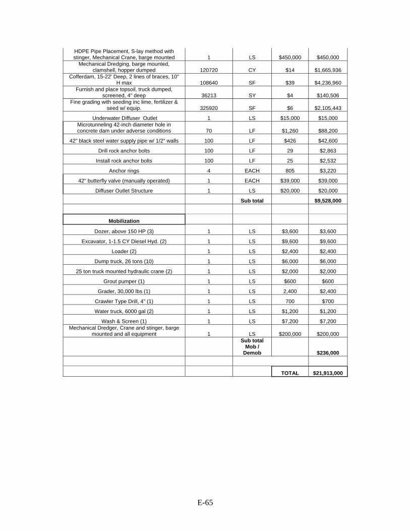
E-65
HDPE Pipe Placement, S-lay method with stinger, Mechanical Crane, barge mounted 1 LS $450,000 $450,000
Mechanical Dredging, barge mounted, clamshell, hopper dumped 120720 CY $14 $1,665,936
Cofferdam, 15-22' Deep, 2 lines of braces, 10" H max 108640 SF $39 $4,236,960
Furnish and place topsoil, truck dumped, screened, 4" deep 36213 SY $4 $140,506
Fine grading with seeding inc lime, fertilizer & seed w/ equip. 325920 SF $6 $2,105,443
Underwater Diffuser Outlet 1 LS $15,000 $15,000 Microtunneling 42-inch diameter hole in concrete dam under adverse conditions 70 LF $1,260 $88,200
42" black steel water supply pipe w/ 1/2" walls 100 LF $426 $42,600
Drill rock anchor bolts 100 LF 29 $2,863
Install rock anchor bolts 100 LF 25 $2,532
Anchor rings 4 EACH 805 $3,220
42" butterfly valve (manually operated) 1 EACH $39,000 $39,000
Diffuser Outlet Structure 1 LS $20,000 $20,000
Sub total $9,528,000
Mobilization
Dozer, above 150 HP (3) 1 LS $3,600 $3,600
Excavator, 1-1.5 CY Diesel Hyd. (2) 1 LS $9,600 $9,600
Loader (2) 1 LS $2,400 $2,400
Dump truck, 26 tons (10) 1 LS $6,000 $6,000
25 ton truck mounted hydraulic crane (2) 1 LS $2,000 $2,000
Grout pumper (1) 1 LS $600 $600
Grader, 30,000 lbs (1) 1 LS 2,400 $2,400
Crawler Type Drill, 4" (1) 1 LS 700 $700
Water truck, 6000 gal (2) 1 LS $1,200 $1,200
Wash & Screen (1) 1 LS $7,200 $7,200 Mechanical Dredger, Crane and stinger, barge
mounted and all equipment 1 LS $200,000 $200,000
Sub total Mob /
Demob $236,000
TOTAL $21,913,000

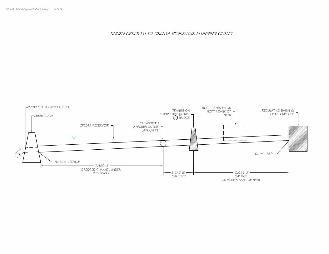

E-66
Measure Name: Convey Cool Bucks Creek PH Flows by Pipeline to Discharge below Cresta Dam Applicable Alternative Category(s): 4, 5; additional measure for Cresta Reach Description of Measure: Construct about 4-mile long pipeline to convey cool Buck Creek PH flows to discharge below Cresta Dam, bypassing Cresta Reservoir. The purpose of this measure is to avoid mixing with warmer ambient waters of Cresta Reservoir. Description of Operations: This measure does not affect PH operations. According to PG&E’s flow measurements in summer 2002-2004, Bucks Creek PH discharges during July and August ranged from 0 to 260 cfs. The cool water flow needed to reduce water temperatures below Cresta Dam is estimated at about 95 cfs and 110 cfs for alternative categories 4 and 5 respectively. The design flow rate is 110 cfs, and Bucks Creek PH discharges exceeding 110 are released to the NFFR. Detailed Description of Facilities Improvements and Design Criteria: Construct a concrete regulating basin at the outlet of Bucks Creek PH. The regulating basin functions to regulate the powerhouse discharge between the NFFR and the proposed bypass pipeline. The regulating basin has an outlet consisting of a large gate valve connected to a 48-inch RCP bypass pipeline. The regulating basin also has a spillway to control the water level in the basin while releasing PH discharges exceeding the bypass flows to the NFFR. The 48-inch RCP bypass pipeline extends from the regulating basin outlet structure to discharge below Cresta Dam. The first segment of the RCP extends about 10,050 ft and is buried under a new access road constructed along the south bank of the NFFR. In the second segment the pipeline transitions to 48-inch HDPE and enters Cresta Reservoir. The HDPE is set and anchored along the bottom of Cresta Reservoir for a distance of 10,050 ft to the dam. The HDPE connects to one of three submerged 92-inch sluice pipes that pass through and discharge below the dam. List of Figures:
• Plan view: Bucks Creek PH to Cresta Dam • Profile: Bucks Creek PH to Cresta Dam Outlet • Detail: Regulating Basin Detail at Bucks Creek PH
Key Design or Construction Uncertainties Requiring Further Study:
• Siting and designing the regulating basin above the floodplain of the NFFR to avoid flood damages requires further study.
• Setting a 48-inch HDPE along the bottom of Cresta Reservoir will be difficult and costly. Design and installation of an anchoring system adequate to withstand the potential forces on the pipe arising from flow momentum and land shifting requires further study.
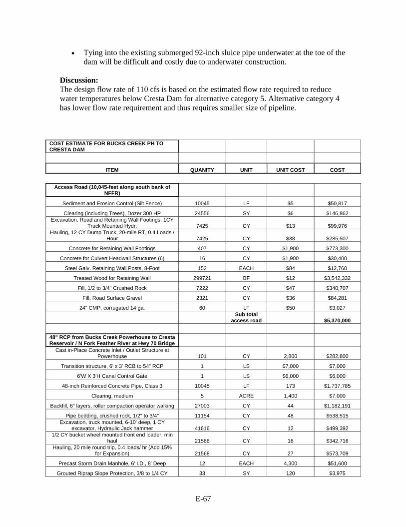
E-67
• Tying into the existing submerged 92-inch sluice pipe underwater at the toe of the dam will be difficult and costly due to underwater construction.
Discussion: The design flow rate of 110 cfs is based on the estimated flow rate required to reduce water temperatures below Cresta Dam for alternative category 5. Alternative category 4 has lower flow rate requirement and thus requires smaller size of pipeline.
COST ESTIMATE FOR BUCKS CREEK PH TO CRESTA DAM
ITEM QUANITY UNIT UNIT COST COST
Access Road (10,045-feet along south bank of
NFFR)
Sediment and Erosion Control (Silt Fence) 10045 LF $5 $50,817
Clearing (including Trees), Dozer 300 HP 24556 SY $6 $146,862 Excavation, Road and Retaining Wall Footings, 1CY
Truck Mounted Hydr. 7425 CY $13 $99,976 Hauling, 12 CY Dump Truck, 20-mile RT, 0.4 Loads /
Hour 7425 CY $38 $285,507
Concrete for Retaining Wall Footings 407 CY $1,900 $773,300
Concrete for Culvert Headwall Structures (6) 16 CY $1,900 $30,400
Steel Galv. Retaining Wall Posts, 8-Foot 152 EACH $84 $12,760
Treated Wood for Retaining Wall 299721 BF $12 $3,542,332
Fill, 1/2 to 3/4" Crushed Rock 7222 CY $47 $340,707
Fill, Road Surface Gravel 2321 CY $36 $84,281
24" CMP, corrugated 14 ga. 60 LF $50 $3,027
Sub total
access road $5,370,000
48" RCP from Bucks Creek Powerhouse to Cresta Reservoir / N Fork Feather River at Hwy 70 Bridge
Cast in-Place Concrete Inlet / Outlet Structure at Powerhouse 101 CY 2,800 $282,800
Transition structure, 6' x 3' RCB to 54" RCP 1 LS $7,000 $7,000
6'W X 3'H Canal Control Gate 1 LS $6,000 $6,000
48-inch Reinforced Concrete Pipe, Class 3 10045 LF 173 $1,737,785
Clearing, medium 5 ACRE 1,400 $7,000
Backfill, 6" layers, roller compaction operator walking 27003 CY 44 $1,182,191
Pipe bedding, crushed rock, 1/2" to 3/4" 11154 CY 48 $538,515 Excavation, truck mounted, 6-10' deep, 1 CY
excavator, Hydraulic Jack hammer 41616 CY 12 $499,392 1/2 CY bucket wheel mounted front end loader, min
haul 21568 CY 16 $342,716 Hauling, 20 mile round trip, 0.4 loads/ hr (Add 15%
for Expansion) 21568 CY 27 $573,709
Precast Storm Drain Manhole, 6' I.D., 8' Deep 12 EACH 4,300 $51,600
Grouted Riprap Slope Protection, 3/8 to 1/4 CY 33 SY 120 $3,975

E-68
Pieces, 18" Thick
Sediment and Erosion Control (Silt Fence) 10045 LF 5 $50,828
Traffic control, signage 1 LS 29,000 $29,000
Traffic control, 2 signals 1 LS 100,000 $100,000
Sub total $5,413,000
48" HDPE from Hwy 70 Bridge to Tie-In at Toe of
Dam
48-inch HDPE 10060 LF 214 $2,152,840 HDPE Pipe Placement, S-lay method with stinger,
Mechanical Crane, barge mounted 1 LS 1,300,000 $1,300,000 Underwater pipe laying preparation of reservoir
bottom 1 LS $3,087,000 $3,087,000 Remove existing metal trash rack at toe of dam (apx
100' underwater) 1 LS 50,000 $50,000 Concrete transition structure, 48" HDPE to 7.7'-dia
sluice pipe 1 LS 12,000 $12,000 Attach48" HDPE to transition structure and sluice
pipe (apx 100' underwater) 1 LS 150,000 $150,000
Sub total $6,752,000
Mobilization
Dozer, above 150 HP (3) 1 LS 3,600 $3,600
Excavator, 1-1.5 CY Diesel Hyd. (2) 1 LS 9,600 $9,600
Loader (2) 1 LS 2,400 $2,400
Dump truck, 26 tons (10) 1 LS 6,000 $6,000
25 ton truck mounted hydraulic crane (2) 1 LS 2,000 $2,000
Grout pumper (1) 1 LS 600 $600
Water truck, 6000 gal (1) 1 LS 1,200 $1,200
Grader, 30,000 lbs (1) 1 LS 2,400 $2,400
Wash & Screen (1) 1 LS 7,200 $7,200 Mechanical Dredger, Crane and stinger, barge
mounted and all equipment 1 LS 200,000 $200,000
Sub total
Mob / Demob $235,000
TOTAL $17,770,000

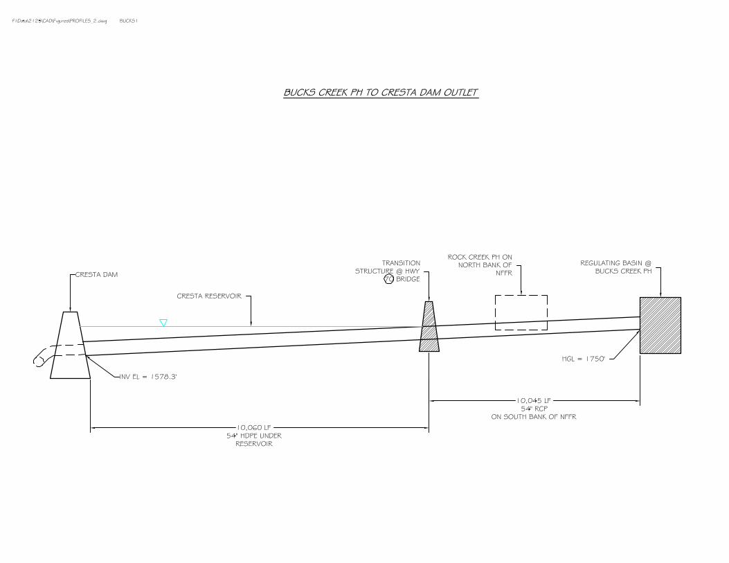


E-69
Measure Name: Divert Cool Lower Rock Creek Reach Flows into a Pipeline to Discharge Below Cresta Dam Applicable Alternative Category(s): 6a; additional measure for Cresta Reach Description of Measure: Construct about 3-mile long pipeline to convey cool lower Rock Creek Reach flows to below Cresta Dam directly, bypassing Cresta Reservoir. The purpose of this measure is to avoid mixing cooler Rock Creek Reach flows with warmer ambient waters of Cresta Reservoir. This measure must be combined with the measure bypassing cold Seneca Reach flows around Belden Reservoir and the measure bypassing lower Belden Reach flows around Rock Creek Reservoir. Description of Operations: This measure does not affect PH operations. Operate the diversion system to divert and convey about 250 cfs through the pipeline and spill the remaining flow over the diversion dam. The diversion rate is supplied by the increased release measure from Rock Creek Dam. The flow accretion from Bucks Creek and Bucks Creek PH inflows would maintain flows for aquatic habitat in the short reach from the diversion dam to the Rock Creek PH discharge. Detailed Description of Facilities Improvements and Design Criteria: Construct a 6-foot high rubber inflatable/deflatable rubber diversion dam on the NFFR about 150 feet upstream of the Rock Creek PH. Except during summer, the rubber dam remains in the deflated position. The diversion dam directs 250 cfs through a 3-mile long pipeline to convey cool lower Rock Creek Reach flows to below Cresta Dam, bypassing Cresta Reservoir. The first segment consists of 66-inch RCP that extends about 150 ft to the Rock Creek PH. The pipe then transitions into a 66-inch Black Steel Pipe (BSP) which is connected to the face of Rock Creek PH and extends about 160 feet to the north bank of the NFFR just downstream of Rock Creek PH. The pipe material then transitions back into 66-inch RCP where it is buried along the shoulder of Highway 70 for approximately 4,155 feet. The pipe then enters Cresta Reservoir and where it transitions to 66-inch HDPE. The HDPE pipe is set and anchored to the reservoir bottom for the last 10,060 feet to Cresta Dam. The end of the 66-inch HDPE connects to one of the three existing submerged 92-inch sluice pipes (currently abandoned) at the toe of the dam which discharges below Cresta Dam. List of Figures:
• Plan view: North Fork Feather River (NFFR), Lower Rock Creek Reach Bypass • Profile: Lower Rock Creek Reach Bypass to Cresta Dam and Details
Key Design or Construction Uncertainties Requiring Further Study:
• Attaching to the existing 7’-8 3/8” I.D. sluice pipe underwater at the toe of Cresta Dam will be difficult and costly due to underwater construction.
• Connecting a 66-inch black steel pipe to the face of the powerhouse and anchoring it against the flow forces of the NFFR requires further study.
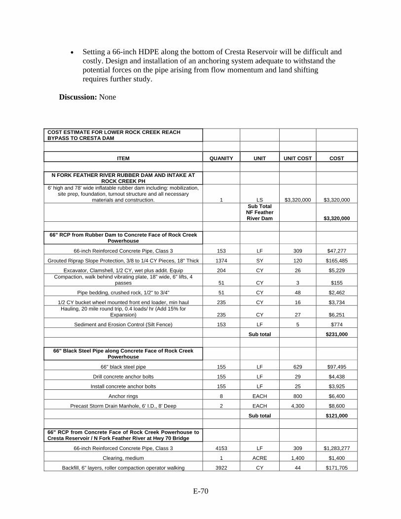
E-70
• Setting a 66-inch HDPE along the bottom of Cresta Reservoir will be difficult and costly. Design and installation of an anchoring system adequate to withstand the potential forces on the pipe arising from flow momentum and land shifting requires further study.
Discussion: None
COST ESTIMATE FOR LOWER ROCK CREEK REACH BYPASS TO CRESTA DAM
ITEM QUANITY UNIT UNIT COST COST
N FORK FEATHER RIVER RUBBER DAM AND INTAKE AT
ROCK CREEK PH 6' high and 78' wide inflatable rubber dam including: mobilization,
site prep, foundation, turnout structure and all necessary materials and construction. 1 LS $3,320,000 $3,320,000
Sub Total NF Feather River Dam $3,320,000
66" RCP from Rubber Dam to Concrete Face of Rock Creek
Powerhouse
66-inch Reinforced Concrete Pipe, Class 3 153 LF 309 $47,277
Grouted Riprap Slope Protection, 3/8 to 1/4 CY Pieces, 18" Thick 1374 SY 120 $165,485
Excavator, Clamshell, 1/2 CY, wet plus addit. Equip 204 CY 26 $5,229 Compaction, walk behind vibrating plate, 18" wide, 6" lifts, 4
passes 51 CY 3 $155
Pipe bedding, crushed rock, 1/2" to 3/4" 51 CY 48 $2,462
1/2 CY bucket wheel mounted front end loader, min haul 235 CY 16 $3,734 Hauling, 20 mile round trip, 0.4 loads/ hr (Add 15% for
Expansion) 235 CY 27 $6,251
Sediment and Erosion Control (Silt Fence) 153 LF 5 $774
Sub total $231,000
66" Black Steel Pipe along Concrete Face of Rock Creek
Powerhouse
66" black steel pipe 155 LF 629 $97,495
Drill concrete anchor bolts 155 LF 29 $4,438
Install concrete anchor bolts 155 LF 25 $3,925
Anchor rings 8 EACH 800 $6,400
Precast Storm Drain Manhole, 6' I.D., 8' Deep 2 EACH 4,300 $8,600
Sub total $121,000
66" RCP from Concrete Face of Rock Creek Powerhouse to Cresta Reservoir / N Fork Feather River at Hwy 70 Bridge
66-inch Reinforced Concrete Pipe, Class 3 4153 LF 309 $1,283,277
Clearing, medium 1 ACRE 1,400 $1,400
Backfill, 6" layers, roller compaction operator walking 3922 CY 44 $171,705

E-71
Pipe bedding, crushed rock, 1/2" to 3/4" 6009 CY 48 $290,115 Excavation, truck mounted, 6-10' deep, 1 CY excavator,
Hydraulic Jack hammer 15035 CY 12 $180,420
1/2 CY bucket wheel mounted front end loader, min haul 12780 CY 16 $203,074 Hauling, 20 mile round trip, 0.4 loads/ hr (Add 15% for
Expansion) 12780 CY 27 $339,948
Precast Storm Drain Manhole, 6' I.D., 8' Deep 14 EACH 4,300 $60,200
Grouted Riprap Slope Protection, 3/8 to 1/4 CY Pieces, 18" Thick 6137 SY 120 $739,140
Remove Gravel shoulder 1126 SY 7 $7,499
Replace Gravel shoulder 375 CY 48 $18,105 Shoulder Compaction, walk behind vibrating plate, 18" wide, 6"
lifts, 4 passes 375 CY 3 $1,136
Sediment and Erosion Control (Silt Fence) 4153 LF 5 $21,014
Remove and reset existing corrugated metal guard rail 4153 LF 35 $144,192
Traffic control, signage 1 LS 29,000 $29,000
Traffic control, 2 signals 1 LS 382,000 $382,000
Sub total $3,872,000
66" HDPE from Hwy 70 Bridge to Tie-In at Toe of Dam
66-inch HDPE 10060 LF 390 $3,923,400 HDPE Pipe Placement, S-lay method with stinger, Mechanical
Crane, barge mounted 1 LS 1,300,000 $1,300,000
Underwater pipe laying preparation of reservoir bottom 1 LS 3,087,000 $3,087,000 Remove existing metal trash rack at toe of dam (apx 100'
underwater) 1 LS 50,000 $50,000
Concrete transition structure, 66" HDPE to 7.7'-dia sluice pipe 1 LS 12,000 $12,000 Attach 66" HDPE to transition structure and sluice pipe (apx 100'
underwater) 1 LS 150,000 $150,000
Sub total $8,522,000
Mobilization
Dozer, above 150 HP (3) 1 LS 3,600 $3,600
Excavator, 1-1.5 CY Diesel Hyd. (2) 1 LS 9,600 $9,600
Loader (2) 1 LS 2,400 $2,400
Dump truck, 26 tons (10) 1 LS 6,000 $6,000
25 ton truck mounted hydraulic crane (2) 1 LS 2,000 $2,000
Crawler Type Drill, 4" (1) 1 LS 700 $700
Grout pumper (1) 1 LS 600 $600
Water truck, 6000 gal (2) 1 LS 1,200 $1,200
Wash & Screen (1) 1 LS 7,200 $7,200 Mechanical Dredger, Crane and stinger, barge mounted and all
equipment 1 LS 200,000 $200,000
Sub total Mob /
Demob $233,000
TOTAL $16,299,000

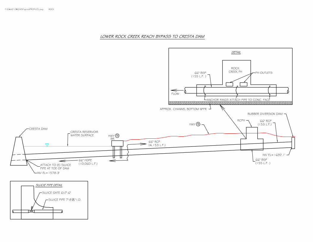
E-72
Measure Name: Convey Cool Water from Poe Adit to Poe Reach Applicable Alternative Category(s): 2, 3, 4; additional measure for Poe Reach Description of Measure: Construct an approximately 2/3-mile long pipeline to deliver cool water from the Poe Adit to the middle of Poe Reach. The purpose of this measure is to reduce water temperature in the lower Poe Reach. Description of Operations: This measure does not affect PH operations. Convey 150 cfs from the Poe Adit to the middle of Poe Reach. Detailed Description of Facilities Improvements and Design Criteria: The delivery pipeline extends from the Poe Tunnel near Bardee’s Bar, through the Poe Adit (the existing horizontal access tunnel leading to the Poe Tunnel) to the middle of the Poe Reach. Flow is collected from the Poe Tunnel, which is an existing underground 17-feet diameter tunnel that delivers water from Poe Reservoir to Poe PH. The Poe Tunnel is accessed through the Poe Adit. The existing butterfly value and tunnel access hole inside the adit is enlarged from 18 to 42-inches and attached to a 42-inch Black Steel Pipe (BSP) buried under the floor of the adit, carrying flow approximately 960 feet outside the adit. The 42-inch BSP is then jack and bored under the railroad tracks and buried under the existing gravel access road the remaining 2,000 feet to Poe Reach, discharging through a manually operated butterfly valve into the Poe Reach just downstream of Bardee’s Bar Road Bridge. Selected portions of the pipe alignment, design and costs were taken from the Black and Veatch Report (Prefeasibility Level Sizing and Cost Estimate Summary Memorandum, 2005). List of Figures:
• Plan view: North Fork Feather River (NFFR) Poe Adit Pipeline. • Profile: Poe Adit to NFFR at Poe Reach.
Key Design or Construction Uncertainties Requiring Further Study:
• It will be difficult and costly to microtunnel through Poe Tunnel from within Poe Adit due to tunneling through concrete in a confined space.
• The unstable spoils pile / hillside under proposed pipe alignment is dangerous requires further study of its stability.
Discussion: This design used diverted flow of 150 cfs from Poe Adit. However, the required discharge for each alternative category differs.

E-73
COST ESTIMATE FOR POE ADIT
ITEM QUANITY UNIT UNIT COST COST
INSIDE ADIT Microtunneling, increase existing 18" bore to 42" (cost for 24" to 48") hole in tunnel under adverse conditions 20 LF $1,260 $25,200
Spoils handling inside tunnel 1/2 CY bucket wheel mounted front end loader, min haul 3 CY $16 $48
Hauling, 20 mile round trip, 0.4 loads/ hr 4 CY $27 $106
Tunnel ventilation, duct, 48", 20ga., spun on site 1000 LF $21 $21,480
Fan, 48" dia, 125 HP, inc. starter 1 EACH $29,000 $29,000 Mob / demob of microtunneling equipment (maximum) 1 EACH $510,000 $510,000
Pipe inside tunnel
42" black steel water supply pipe w/ 1/2" walls 960 LF $426 $408,960 Excavation by hand 2-6' deep in heavy soil inc tamping 1271 CY $94 $118,839
Pipe bedding, crushed rock, 1/2" to 3/4" 929 CY $48 $44,852 Compaction, walk behind vibrating plate, 18" wide, 6" lifts, 4 passes 929 CY $3 $2,815 1/2 CY bucket wheel mounted front end loader, min haul 1271 CY $16 $20,196
Hauling, 20 mile round trip, 0.4 loads/ hr 1271 CY $27 $33,809
42" butterfly valve (manually operated) 1 EACH $39,000 $39,000
90 degree 42" elbow 2 EACH $19,000 $38,000
INSIDE ADIT $1,292,000
ITEM QUANITY UNIT COST
OUTSIDE ADIT
Pipe outside gravel road
42" black steel water supply pipe w/ 1/2" walls 402 LF $426 $171,252 1/2 CY bucket wheel mounted front end loader, min haul 532 CY $16 $8,453
Hauling, 20 mile round trip, 0.4 loads/ hr 532 CY $27 $14,151 Compaction, walk behind vibrating plate, 18" wide, 6" lifts, 4 passes 389 CY $3 $1,179
Pipe bedding, crushed rock, 1/2" to 3/4" 389 CY $48 $18,781 Excavation, truck mounted, 6-10' deep, 1 CY excavator, Rock, drill & blast 532 CY $138 $73,613
45 degree bend, 42" 3 EACH $10,000 $30,000
90 degree 42" elbow 1 EACH $19,000 $19,000
Pipe in gravel road
42" black steel water supply pipe w/ 1/2" walls 1614 LF $426 $687,564

E-74
Excavation, truck mounted, 6-10' deep, 1 CY excavator, Hydraulic Jack hammer 2137 CY $12 $25,644
Pipe bedding, crushed rock, 1/2" to 3/4" 1562 CY $48 $75,413 Compaction, walk behind vibrating plate, 18" wide, 6" lifts, 4 passes 1562 CY $3 $4,733 1/2 CY bucket wheel mounted front end loader, min haul 2137 CY $16 $33,957
Hauling, 20 mile round trip, 0.4 loads/ hr 2137 CY $27 $56,844
22.5 degree bend, 42" 1 EACH $10,000 $10,000
45 degree bend, 42" 4 EACH $10,000 $40,000
90 degree 42" elbow 1 EACH $19,000 $19,000 Resurface gravel road, 12' wide and apx 1614' long 19368 SF $2 $37,380
Under Railroad
42" black steel water supply pipe w/ 1/2" walls 33 LF $426 $14,058
Horizontal boring, railroad work, 42" dia. 33 LF $580 $19,140
Jacking pits inc. mob. / demob., maximum 1 EACH $22,000 $22,000 1/2 CY bucket wheel mounted front end loader, min haul 29 CY $16 $461
Hauling, 20 mile round trip, 0.4 loads/ hr 29 CY $27 $771
Pipe bedding, crushed rock, 1/2" to 3/4" 17 CY $48 $821
Outlet
Concrete Outlet Structure 1 LS $30,000 $30,000
42" butterfly valve (manually operated) 1 EACH $40,000 $40,000
All sections
Site clean up & repairs 1 EACH $172,000 $172,000
Signage & traffic control 1 EACH $34,000 $34,000
Silt fence 4660 LF $5 $21,483
Site Demolition Work 1 EACH $2,900 $2,900
General Equipment Mobilization 1 EACH $21,000 $21,000
OUTSIDE ADIT $1,706,000
COMPLETE BYPASS (Rounded) $2,998,000
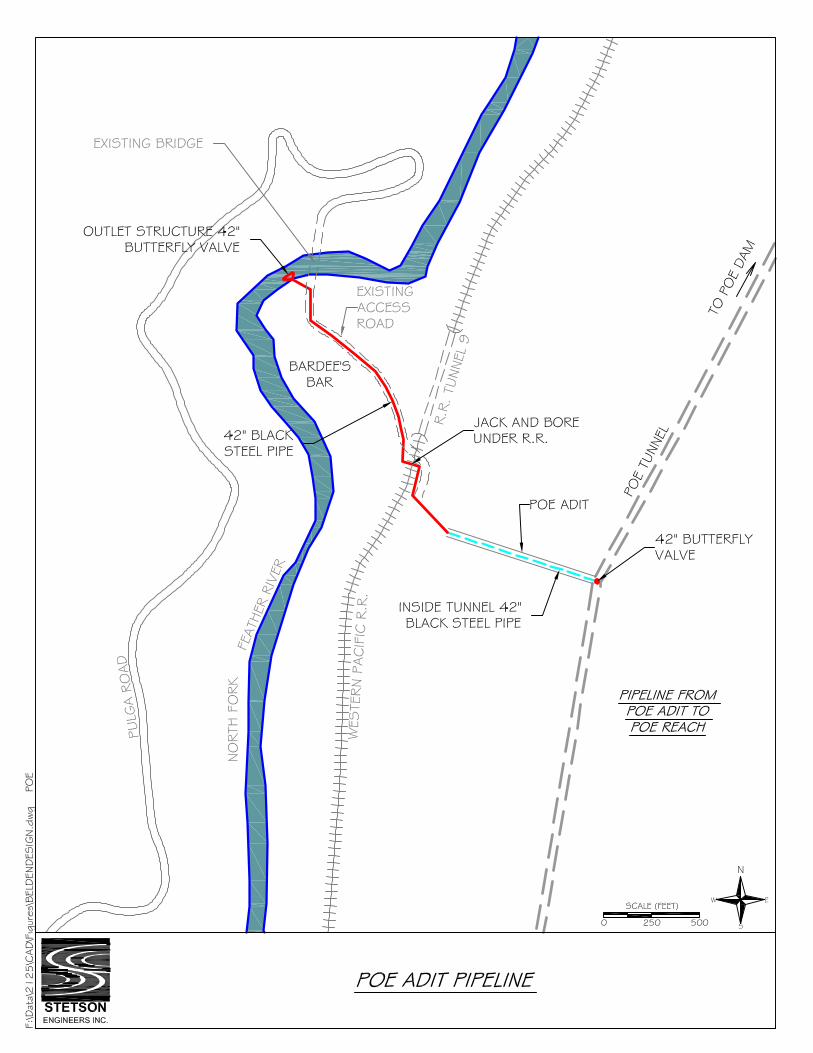


E-75
Measure Name: Divert Lower Cresta Reach Flows and Convey by Submerged Pipeline to Discharge below Poe Dam Applicable Alternative Category(s): 6a; additional measure for Poe Reach Description of Measure: Construct about 3-mile long pipeline to convey cold lower Cresta Reach flows to below Poe Dam directly, bypassing Poe Reservoir. The purpose of this measure is to avoid mixing cool Cresta Reach flows with warmer ambient waters of Poe Reservoir. This measure must be combined with the measure bypassing cold Seneca Reach flows around Belden Reservoir, the measure bypassing lower Belden Reach flows around Rock Creek Reservoir, and the measure bypassing lower Rock Creek flows around Cresta Reservoir. Description of Operations: This measure does not affect PH operations. Operate the diversion system to divert 250 cfs of lower Cresta Reach flows to below Poe Dam and spill the remaining flow over the diversion dam. The diversion rate is supplied by the increased release measure from Cresta Dam. The flow accretion from Grizzly Creek inflows would maintain flows for aquatic habitat in the short reach from the diversion dam to the Cresta PH discharge. Detailed Description of Facilities Improvements and Design Criteria: Construct a 7-foot high inflatable/deflatable rubber diversion dam at the lower end of Cresta Reach just upstream of the Cresta PH. Except during summer, the rubber dam would remain in the deflated position. Construct an approximately 3 mile long pipeline to convey cool Cresta Reach flows captured behind the dam to connect to the existing outlet structure for discharge below Poe Dam. The pipeline starts at the diversion dam and extends about 3 mile to connect to the existing outlet at the bottom of Belden Reservoir. The first segment of the pipeline consists of about 170-feet of 66-inch RCP. The second segment transitions into about 280 feet of 66-inch black steel pipe (BSP) which is connected to the face of Cresta PH and extending to the southeast bank of the NFFR just downstream of Cresta PH. The pipe material then transitions back into 66-inch RCP where it is buried underneath a small existing access road along the southeast bank of the NFFR for approximately 934 feet. The pipe then transitions to 66-inch HDPE and is set anchored to the bottom of Poe Reservoir for the remaining 8,394 feet down to the toe of the dam. The 66-inch HDPE is connected to the existing 66-inche diameter outlet which discharges below Poe Dam. List of Figures:
• Plan view: Lower Cresta Reach Bypass to Poe Dam. • Profile: NFFR Lower Cresta Reach Bypass to Poe Dam

E-76
Key Design or Construction Uncertainties Requiring Further Study:
• Connecting a 66-inch black steel pipe to the face the powerhouse will be difficult and costly to anchor against the flow forces of the NFFR and the powerhouse outlet.
• Setting a 66-inch HDPE along the bottom of Cresta Reservoir will be difficult and costly. Design and installation of an anchoring system adequate to withstand the potential forces on the pipe arising from flow momentum and land shifting requires further study.
• Attaching to the existing 66-inch outlet pipe at the toe of the dam will be difficult and costly due to underwater construction.
Discussion: None

E-77
COST ESTIMATE FOR LOWER CRESTA REACH BYPASS TO POE DAM OUTLET
ITEM QUANITY UNIT UNIT COST COST
N FORK FEATHER RIVER RUBBER DAM AND INTAKE AT
CRESTA PH 7' high and 84' wide inflatable rubber dam including: mobilization, site
prep, foundation, turnout structure and all necessary materials and construction. 1 LS $4,170,000 $4,170,000
Sub Total NF Feather River Dam $4,170,000
66" RCP from Rubber Dam to Concrete Along Face of Cresta
Powerhouse
66-inch Reinforced Concrete Pipe, Class 3 172 LF 309 $53,148
Grouted Riprap Slope Protection, 3/8 to 1/4 CY Pieces, 18" Thick 354 SY 120 $42,636
Excavator, Clamshell, 1/2 CY, wet plus addit. Equip 650 CY 26 $16,660
Backfill, 6" layers, roller compaction operator walking 108 CY 44 $4,728
Compaction, walk behind vibrating plate, 18" wide, 6" lifts, 4 passes 357 CY 3 $1,082
Pipe bedding, crushed rock, 1/2" to 3/4" 249 CY 48 $12,022
1/2 CY bucket wheel mounted front end loader, min haul 529 CY 16 $8,406
Hauling, 20 mile round trip, 0.4 loads/ hr (Add 15% for Expansion) 529 CY 27 $14,071
Sediment and Erosion Control (Silt Fence) 172 LF 5 $870
Sub total $154,000
66" Black Steel Pipe along Concrete Face of Cresta Powerhouse
66" black steel pipe 278 LF 629 $174,862
Drill concrete anchor bolts 278 LF 29 $7,959
Install concrete anchor bolts 278 LF 25 $7,039
Anchor rings 8 EACH 800 $6,400
Precast Storm Drain Manhole, 6' I.D., 8' Deep 2 EACH 4,300 $8,600
Sub total $205,000
66" RCP from Concrete Face of Cresta Powerhouse to N Fork Feather River / Poe Reservoir
66-inch Reinforced Concrete Pipe, Class 3 934 LF 309 $288,606
Clearing, medium 0.5 ACRE 1,400 $700
Compaction, walk behind vibrating plate, 18" wide, 6" lifts, 4 passes 1939 CY 3 $5,875
Backfill, 6" layers, roller compaction operator walking 588 CY 44 $25,743
Pipe bedding, crushed rock, 1/2" to 3/4" 1351 CY 48 $65,226 Excavation, truck mounted, 6-10' deep, 1 CY excavator, Hydraulic
Jack hammer 3528 CY 12 $42,336
1/2 CY bucket wheel mounted front end loader, min haul 2874 CY 16 $45,668
Hauling, 20 mile round trip, 0.4 loads/ hr (Add 15% for Expansion) 2874 CY 27 $76,448
Precast Storm Drain Manhole, 6' I.D., 8' Deep 3 EACH 4,300 $12,900
Grouted Riprap Slope Protection, 3/8 to 1/4 CY Pieces, 18" Thick 1920 SY 120 $231,245

E-78
Sediment and Erosion Control (Silt Fence) 934 LF 5 $4,726
Remove and reset existing corrugated metal guard rail 934 LF 35 $32,428
Traffic control, signage 1 LS 29,000 $29,000
Traffic control, 2 signals 1 LS 51,000 $51,000
Sub total $912,000
66" HDPE from Poe Rseervoir near Cresta PH to Tie-In at Toe of
Dam
66-inch HDPE 8394 LF 390 $3,273,660 HDPE Pipe Placement, S-lay method with stinger, Mechanical Crane,
barge mounted 1 LS 1,300,000 $1,300,000
Underwater pipe laying preparation of reservoir bottom 1 LS 2,490,000 $2,490,000
Microtunneling, increase existing 36" fish water bore in dam to 66" 50 LF 2,000 $100,000
Concrete transition structure, 66" HDPE to 66-dia fish water pipe 1 LS 12,000 $12,000 Attach 66" HDPE to transition structure and expanded fish water pipe
(apx 35' underwater) 1 LS 150,000 $150,000
66-inch hydraulic operated butterfly valve 1 LS 66,000 $66,000
Sub total $7,392,000
Mobilization
Dozer, above 150 HP (3) 1 LS 3,600 $3,600
Excavator, 1-1.5 CY Diesel Hyd. (2) 1 LS 9,600 $9,600
Loader (2) 1 LS 2,400 $2,400
Dump truck, 26 tons (10) 1 LS 6,000 $6,000
25 ton truck mounted hydraulic crane (2) 1 LS 2,000 $2,000
Crawler Type Drill, 4" (1) 1 LS 700 $700
Grout pumper (1) 1 LS 600 $600
Water truck, 6000 gal (2) 1 LS 1,200 $1,200
Wash & Screen (1) 1 LS 7,200 $7,200 Mechanical Dredger, Crane and stinger, barge mounted and all
equipment 1 LS 200,000 $200,000
Sub total Mob /
Demob $233,000
TOTAL $13,066,000

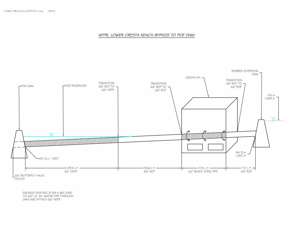

E-79
Measure Name: Construct Mechanical Water Chillers near Rock Creek, Cresta, and Poe Dams Applicable Alternative Category(s): 4, 5, 6 Description of Measure: Construct a mechanical water chiller to cool reservoir water and deliver it back to the reach just below the Rock Creek, Cresta, and Poe Dams. The purpose of this measure is to reduce the water temperature of flows below the dams. A water chiller is a machine that removes heat from water by employing a vapor-compression or absorption-refrigeration cycle. Chillers typically made as complete packaged closed-loop systems, including the evaporator, compressor, condenser, and expansion valve (see the following figure). Warm water entering the chiller inlet is cooled by a coil-confined refrigerant and the chilled water is discharged from the chiller outlet. The heat energy taken out of the warm water by the refrigerant is released to the environment through an air- or water-cooled condenser.
Conceptual process flowchart of mechanical water chillers The cycle begins in the evaporator where a liquid refrigerant flows over the evaporator tube bundle and evaporates, absorbing heat from the chilled water circulating through the bundle. The refrigerant vapor is drawn out of the evaporator by the compressor. The compressor then “pumps” the refrigerant vapor to the condenser raising its pressure and temperature. The refrigerant condenses on or in the condenser tubes, giving up its heat to the cooling air (or water). The high pressure liquid refrigerant from the condenser then passes through the expansion device that reduces the refrigerant pressure and temperature as it enters the evaporator. The refrigerant again flows over the chilled water coils absorbing more heat and completing the cycle. Description of Operations: This measure does not affect PH operations. Operate the chiller system to divert 150 cfs from Rock Creek Reservoir, 175 cfs from Cresta
Compressor
Evaporator
Condenser
Expansion valve
Water in
Water out
Compressor
Evaporator
Condenser
Expansion valve
Water in
Water out
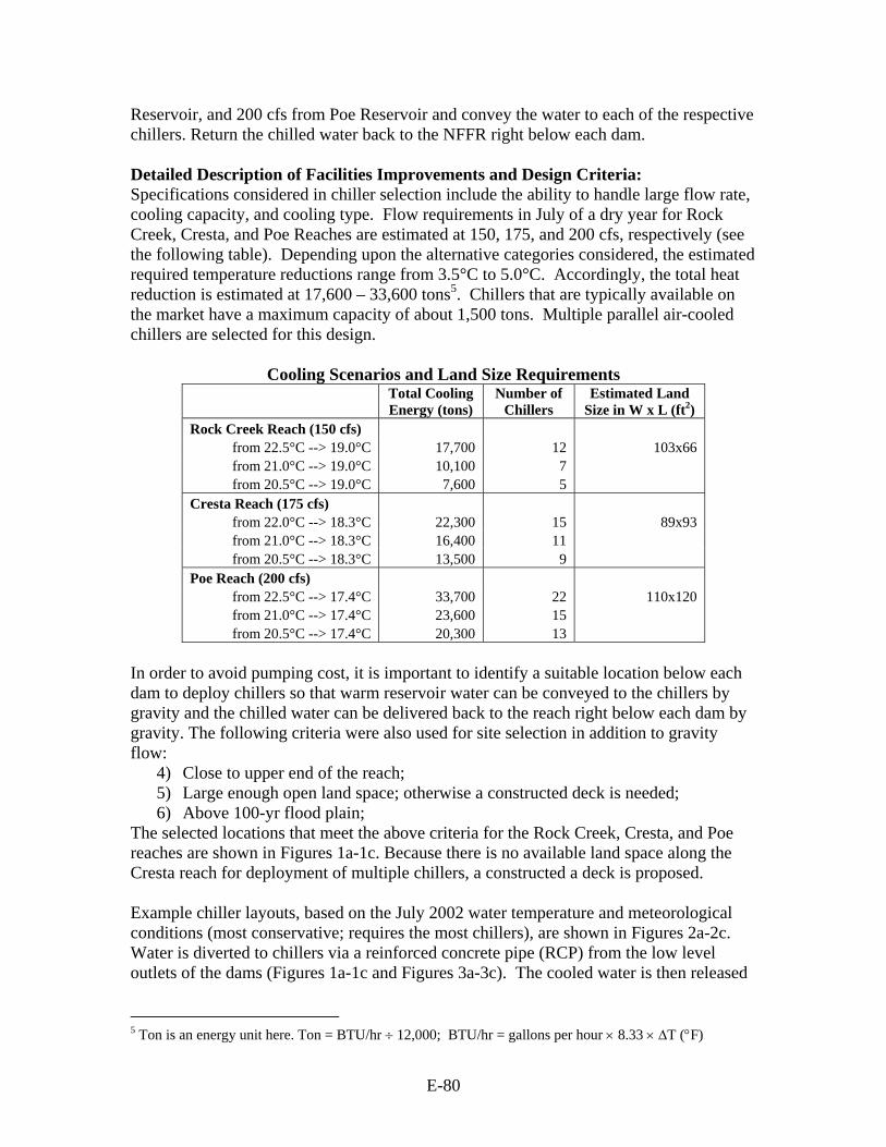
E-80
Reservoir, and 200 cfs from Poe Reservoir and convey the water to each of the respective chillers. Return the chilled water back to the NFFR right below each dam. Detailed Description of Facilities Improvements and Design Criteria: Specifications considered in chiller selection include the ability to handle large flow rate, cooling capacity, and cooling type. Flow requirements in July of a dry year for Rock Creek, Cresta, and Poe Reaches are estimated at 150, 175, and 200 cfs, respectively (see the following table). Depending upon the alternative categories considered, the estimated required temperature reductions range from 3.5°C to 5.0°C. Accordingly, the total heat reduction is estimated at 17,600 – 33,600 tons5. Chillers that are typically available on the market have a maximum capacity of about 1,500 tons. Multiple parallel air-cooled chillers are selected for this design.
Cooling Scenarios and Land Size Requirements
Total Cooling Energy (tons)
Number of Chillers
Estimated Land Size in W x L (ft2)
Rock Creek Reach (150 cfs) from 22.5°C --> 19.0°C 17,700 12 103x66 from 21.0°C --> 19.0°C 10,100 7 from 20.5°C --> 19.0°C 7,600 5
Cresta Reach (175 cfs) from 22.0°C --> 18.3°C 22,300 15 89x93 from 21.0°C --> 18.3°C 16,400 11 from 20.5°C --> 18.3°C 13,500 9
Poe Reach (200 cfs) from 22.5°C --> 17.4°C 33,700 22 110x120 from 21.0°C --> 17.4°C 23,600 15 from 20.5°C --> 17.4°C 20,300 13
In order to avoid pumping cost, it is important to identify a suitable location below each dam to deploy chillers so that warm reservoir water can be conveyed to the chillers by gravity and the chilled water can be delivered back to the reach right below each dam by gravity. The following criteria were also used for site selection in addition to gravity flow:
4) Close to upper end of the reach; 5) Large enough open land space; otherwise a constructed deck is needed; 6) Above 100-yr flood plain;
The selected locations that meet the above criteria for the Rock Creek, Cresta, and Poe reaches are shown in Figures 1a-1c. Because there is no available land space along the Cresta reach for deployment of multiple chillers, a constructed a deck is proposed. Example chiller layouts, based on the July 2002 water temperature and meteorological conditions (most conservative; requires the most chillers), are shown in Figures 2a-2c. Water is diverted to chillers via a reinforced concrete pipe (RCP) from the low level outlets of the dams (Figures 1a-1c and Figures 3a-3c). The cooled water is then released
5 Ton is an energy unit here. Ton = BTU/hr ÷ 12,000; BTU/hr = gallons per hour × 8.33 × ∆T (°F)
E-81
back by way of another RCP to the upper end of each reach, i.e., just below the reservoir dam. List of Figures:
• Figures 1a – 1c: Plan view of chiller locations and piping: • Figures 2a – 2c: Plan view of example chiller layouts and piping • Figures 3a – 3c: Profile of chiller designs
Key Design or Construction Uncertainties Requiring Further Study: • Siting and design of the chiller for a confirmed location above the 100-year
floodplain to avoid flood damages while being able to deliver the chilled water back to the NFFR right below each dam by gravity requires further study.
• The design was mainly based on the vendor’s quote which requires further verification.
Discussion: A mechanical cooling tower was also considered to cool reservoir water. However, preliminary analysis indicates that a mechanical cooling tower is not feasible to cool waters in Rock Creek, Cresta, and Poe Reservoirs to below 20°C because the ambient wet bulb temperatures at the sites are already close to 20°C (or 68°F) in July and August based on the meteorological data observed at Rock Creek Dam station and Poe Dam station by PG&E. Theoretically, the ambient wet bulb temperature must be lower than target temperature by at least 5°F (or about 3°C) to make a mechanical cooling tower feasible. (Note: Wet bulb temperature is the temperature indicated by a moistened thermometer bulb exposed to the air flow. The evaporation of water from the thermometer has a cooling effect, so the wet bulb temperature is always lower than the dry bulb temperature (i.e., temperature measured by a normal thermometer) except when there is 100% relative humidity.)

E-82
Cost Estimates of Each Installation of Chillers
Cost of Chillers Annual Energy Consumption
Number of
Chillers
Unit Chiller
Cost ($) 1
Unit Startup Fee ($) 1
Subtotal ($)
Cost of Construction
($)
Total Installation Cost
($) Unit Power
Demand at Full load (kW) 1
Running Time Period
(days/year)
Energy Consumption
(KWh ×106/year)
Rock Creek Reach from 22.5°C --> 19.0°C 12 4,620,000 6,096,000 12.11 from 21.0°C --> 19.0°C 7 382,000 3,000 2,695,000 1,476,000 2 4,171,000 678.4 62 7.07 from 20.5°C --> 19.0°C 5 1,925,000 3,401,000 5.05
Cresta Reach from 22.0°C --> 18.3°C 15 5,775,000 8,349,000 15.14 from 21.0°C --> 18.3°C 11 382,000 3,000 4,235,000 2,574,000 3 6,809,000 678.4 62 11.1 from 20.5°C --> 18.3°C 9 3,465,000 6,039,000 9.09
Poe Reach from 22.5°C --> 17.4°C 22 8,470,000 11,750,000 22.21 from 21.0°C --> 17.4°C 15 382,000 3,000 5,775,000 3,280,000 4 9,055,000 678.4 62 15.14 from 20.5°C --> 17.4°C 13 5,005,000 8,285,000 13.12
1) From vendor’s quote, see attached. 2) Includes two 48-inch, 900 ft long reinforced concrete pipes and installation. 3) Includes two 48-inch, 350 ft long reinforced concrete pipes and installation and constructed deck for chiller deployment. 4) Includes two 48-inch, 2,000 ft long reinforced concrete pipes and installation

Figure 1a. Plan view of chiller location on Rock Creek Reach; Pipe size = 4 ft; flow rate = 150 cfs
Figure 1b. Plan view of chiller location on Cresta Reach; Pipe size = 4 ft; flow rate = 175 cfs
Figure 1c. Plan view of chiller location on Poe Reach; Pipe size = 4 ft; flow rate = 200 cfs
69 ft33 ft
15 ft9 ft
69 ft33 ft
15 ft9 ft
69 ft33 ft
15 ft9 ft
70 ft
70 ft
15 ft
9 ft
To Stream
70 ft
70 ft
15 ft
9 ft
To Stream
75 ft 75 ft
15 ft 9 ft
75 ft 75 ft
15 ft 9 ft
75 ft 75 ft
15 ft 9 ft
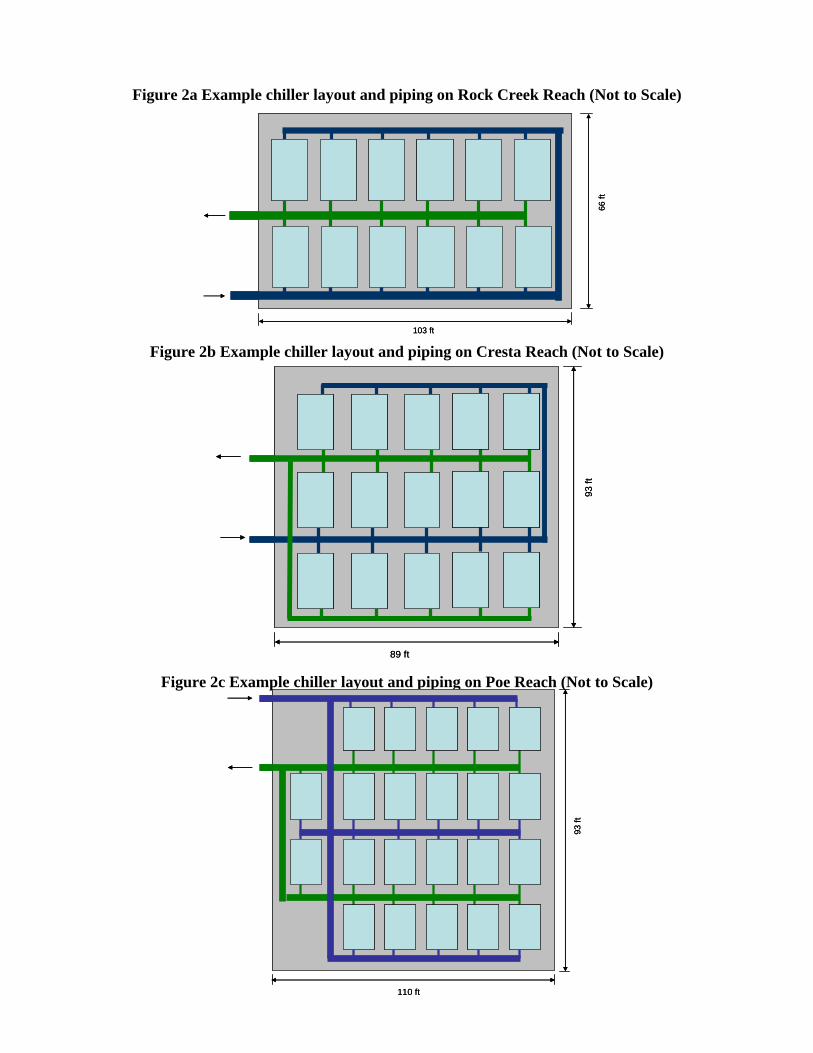
Figure 2a Example chiller layout and piping on Rock Creek Reach (Not to Scale)
Figure 2b Example chiller layout and piping on Cresta Reach (Not to Scale)
Figure 2c Example chiller layout and piping on Poe Reach (Not to Scale)
66 ft
103 ft
66 ft
103 ft
89 ft
93 ft
89 ft
93 ft
110 ft
93 ft
110 ft
93 ft

Figure 3a Profile of chiller design on Rock Creek Reach; Chillers are on river bank
(Not to Scale).
Figure 3b Profile of chiller design on Cresta Reach; Chillers are on a constructed deck (Not to Scale).
Figure 3c Profile of chiller design on Poe Reach; Chillers are on river bank (Not to Scale).