APM1,PM2.5, and PM10 Airborne Particle Detector With Laser ...
9
1988 IEEE SENSORS JOURNAL, VOL. 20, NO. 4, FEBRUARY 15, 2020 A PM 1 , PM 2.5 , and PM 10 Airborne Particle Detector With Laser Illumination Stabilized by Optical Feedback Cyuyeol Rhee , Han Yang, and Suhwan Kim , Senior Member, IEEE Abstract —This paper presents a read-out integrated circuit (ROIC) for PM 1 , PM 2.5 , and PM 10 airborne particle detector with a laser diode. The ROIC has a monitoring photodi- ode, which provides negative feedback through an automatic power control circuit. This adjusts the driving current to the laser diode, and thus stabilizes the illumination level. Offset compensation circuit in analog front-end eliminates the large offset voltage introduced by stray light reaching the measuring photodiode. A digital back-end analyses each pulse to determine the corresponding particle size, and also linearizes the response, which would otherwise drop off for smaller particles. The ROIC was fabricated in a 0.18 μm CMOS process. It has an area of 6.27 mm 2 and draws 10 mW at 5 V. The ROIC is incorporated in a particle detector which is tested against an aerosol spectrometer. For particle concentrations up to 100 μg/m 3 , this detector was found to have an accuracy of ± 10 μg/m 3 for PM 10 and PM 2.5 , and ± 15 μg/m 3 for PM 1 . At higher concentrations, up to 1000 μg/m 3 , the corresponding accuracies are ± 5 % and ± 10 %. Within the temperature range of 0 ◦ C to 50 ◦ C, the effective resolution of the detector changes only from 8.78 bits to 8.97 bits. Index Terms— Airborne particle detector, particulate matter detector, laser diode, optical feedback. I. I NTRODUCTION A IRBORNE particles with an aerodynamic diameter of less than 10 μm (PM 10 ), and fine particles with an aerodynamic diameter less than 2.5 μm (PM 2.5 ) have been shown to cause respiratory damage [1], [2]. Particles between 8 μm and 10 μm mostly remain in the upper parts of the respiratory system [3], but PM 2.5 can travel down to the lungs, making a more significant contribution to respiratory disorders [4]. A recent study suggests that PM 1 , particles with a size below 1 μm, travel through the cell membranes of the alveoli, and damage the arterial lining [4]. Airborne particles can be detected by gravimetric [5], capacitive [6]–[7], or optical techniques [8]–[12]. In gravimetric measurement, the accumulated particles on a membrane filter are weighed [5]. This provides accurate results Manuscript received September 9, 2019; revised October 19, 2019; accepted October 19, 2019. Date of publication October 22, 2019; date of current version January 24, 2020. The associate editor coor- dinating the review of this article and approving it for publication was Prof. Diego Barrettino. (Corresponding author: Suhwan Kim.) C. Rhee and S. Kim are with the Department of Electrical and Computer Engineering, Seoul National University, Seoul 08826, South Korea (e-mail: [email protected]). H. Yang was with the Department of Electrical and Computer Engineer- ing, Seoul National University, Seoul 08826, South Korea. He is now with Samsung Electronics, Hwaseong 18448, South Korea. Digital Object Identifier 10.1109/JSEN.2019.2949008 for the concentration and size of particles but is necessarily slow. Capacitive measurement detects the change produced by particles deposited between electrodes [6]. This method can be implemented on a chip and provides much faster reading, real-time detection of particles, and integration into a single chip. However, the sensor must be cleaned periodically using mechanical vibrations or a jet of air [6]. Optical measurement determines the amount of light from a laser diode (LD), which is scattered by particles. Air containing particles is directed in front of a laser beam. When this happens, light is momentarily scattered by the particle, and this scattered light is received by a photodiode with a rapid response. Classifying the pulses by amplitude and counting the number of pulses in each amplitude range allow the concentration of each type of particle to be estimated. This technique can detect a wide range of particles from PM 10 down to PM 1 because laser diodes are coherent, efficient, and have higher output power than light-emitting diodes. However, the characteristics of the laser diodes are dependent on temperature and component aging. To compensate for the drift due to temperature and aging, an automatic power control (APC) circuit for the laser diode is required [13]. Moreover, the laser diode is turned on and off periodically to increase the lifetime of the laser diode. In optical measurement, a photodiode interfaced with the read-out integrated circuit (ROIC) passes a current 1558-1748 © 2019 IEEE. Personal use is permitted, but republication/redistribution requires IEEE permission. See https://www.ieee.org/publications/rights/index.html for more information.
Transcript of APM1,PM2.5, and PM10 Airborne Particle Detector With Laser ...
1988 IEEE SENSORS JOURNAL, VOL. 20, NO. 4, FEBRUARY 15, 2020
A PM1, PM2.5, and PM10 Airborne ParticleDetector With Laser Illumination Stabilized
by Optical FeedbackCyuyeol Rhee , Han Yang, and Suhwan Kim , Senior Member, IEEE
Abstract—This paper presents a read-out integrated circuit(ROIC) for PM1, PM2.5, and PM10 airborne particle detectorwith a laser diode. The ROIC has a monitoring photodi-ode, which provides negative feedback through an automaticpower control circuit. This adjusts the driving current tothe laser diode, and thus stabilizes the illumination level.Offset compensation circuit in analog front-end eliminatesthe large offset voltage introduced by stray light reachingthe measuring photodiode. A digital back-end analyses eachpulse to determine the corresponding particle size, and alsolinearizes the response, which would otherwise drop off forsmaller particles. The ROIC was fabricated in a 0.18 µm CMOSprocess. It has an area of 6.27 mm2 and draws 10 mW at 5 V.The ROIC is incorporated in a particle detector which is tested against an aerosolspectrometer.For particle concentrationsup to 100 µg/m3, this detector was found to have an accuracy of ± 10 µg/m3 for PM10 and PM2.5, and ± 15 µg/m3 for PM1.At higher concentrations, up to 1000 µg/m3, the corresponding accuracies are ± 5 % and ± 10 %. Within the temperaturerange of 0 ◦C to 50 ◦C, the effective resolution of the detector changes only from 8.78 bits to 8.97 bits.
Index Terms— Airborne particle detector, particulate matter detector, laser diode, optical feedback.
I. INTRODUCTION
A IRBORNE particles with an aerodynamic diameter ofless than 10 μm (PM10), and fine particles with an
aerodynamic diameter less than 2.5 μm (PM2.5) have beenshown to cause respiratory damage [1], [2]. Particles between8 μm and 10 μm mostly remain in the upper parts of therespiratory system [3], but PM2.5 can travel down to thelungs, making a more significant contribution to respiratorydisorders [4]. A recent study suggests that PM1, particles witha size below 1 μm, travel through the cell membranes of thealveoli, and damage the arterial lining [4].
Airborne particles can be detected by gravimetric[5], capacitive [6]–[7], or optical techniques [8]–[12].In gravimetric measurement, the accumulated particles on amembrane filter are weighed [5]. This provides accurate results
Manuscript received September 9, 2019; revised October 19, 2019;accepted October 19, 2019. Date of publication October 22, 2019;date of current version January 24, 2020. The associate editor coor-dinating the review of this article and approving it for publication wasProf. Diego Barrettino. (Corresponding author: Suhwan Kim.)
C. Rhee and S. Kim are with the Department of Electrical andComputer Engineering, Seoul National University, Seoul 08826,South Korea (e-mail: [email protected]).
H. Yang was with the Department of Electrical and Computer Engineer-ing, Seoul National University, Seoul 08826, South Korea. He is now withSamsung Electronics, Hwaseong 18448, South Korea.
Digital Object Identifier 10.1109/JSEN.2019.2949008
for the concentration and size of particles but is necessarilyslow. Capacitive measurement detects the change produced byparticles deposited between electrodes [6]. This method canbe implemented on a chip and provides much faster reading,real-time detection of particles, and integration into a singlechip. However, the sensor must be cleaned periodically usingmechanical vibrations or a jet of air [6]. Optical measurementdetermines the amount of light from a laser diode (LD),which is scattered by particles. Air containing particles isdirected in front of a laser beam. When this happens, light ismomentarily scattered by the particle, and this scattered lightis received by a photodiode with a rapid response. Classifyingthe pulses by amplitude and counting the number of pulsesin each amplitude range allow the concentration of each typeof particle to be estimated. This technique can detect a widerange of particles from PM10 down to PM1 because laserdiodes are coherent, efficient, and have higher output powerthan light-emitting diodes. However, the characteristics of thelaser diodes are dependent on temperature and componentaging. To compensate for the drift due to temperature andaging, an automatic power control (APC) circuit for the laserdiode is required [13]. Moreover, the laser diode is turned onand off periodically to increase the lifetime of the laser diode.
In optical measurement, a photodiode interfaced withthe read-out integrated circuit (ROIC) passes a current
1558-1748 © 2019 IEEE. Personal use is permitted, but republication/redistribution requires IEEE permission.See https://www.ieee.org/publications/rights/index.html for more information.
RHEE et al.: PM1, PM2.5, AND PM10 AIRBORNE PARTICLE DETECTOR WITH LASER ILLUMINATION 1989
proportional to the scattered light. A high-gain and low-noisetransimpedance amplifier amplifies low-level current, and DCoffset current that is caused by ambient light and the darkleakage of the photodiode. This DC offset current causessaturation of ROIC reducing the signal-to-noise ratio (SNR)of a PM detector. This offset can be reduced by correlateddouble sampling (CDS) technique [8]. This is the standardmethod of eliminating a DC offset, but it experiences noise-folding, occupies a large area, and consumes more power thancontinuous-time circuits. One alternative approach [14]–[16] isthe use of a current-steering digital-to-analog converter (DAC)to eliminate the DC offset precisely; but this can generateenough noise to reduce the SNR significantly, mandatingthe introduction of noise reduction techniques or increase ofarea.
In this paper, we introduce an integrated particle detector formonitoring PM1, PM2.5, and PM10 airborne particles, in whichLD-on time-synchronized offset compensation improves thedynamic range (DR) and SNR of the PM detector whileminimizing additional power consumption, noise, and area.The offset compensation has been achieved by introducing amismatch of the transconductance between the input differen-tial pair of the offset compensation circuit. The temperaturedependence of the laser diode and the ROIC is handled byan APC circuit, which maintains the brightness of the laserdiode using a feedback loop with an auxiliary photodiodewhich is encapsulated so that it is not affected by the particles.Our ROIC has been fabricated in a 0.18 μm CMOS processand built into a particle detector to assess the performanceof the ROIC. This detector can measure particle density overconcentrations up to 1000 μg/m3. The accuracy in the con-centration of PM1 between 0 and 100 μg/m3 is ± 15 μg/m3,and between 100 and 1000 μg/m3, it is ± 10 %. The variationin the effective resolution is only 0.21 bits in the temperaturerange of 0 ◦C to 50 ◦C.
The rest of this paper is organized as follows. In Section II,we describe the structure and operation of our optical airborneparticle detector. We describe the analog front-end (AFE) cir-cuit in Section III, and the digital back-end logic in Section IV.In Section V, we describe the APC circuit, and in Section VI,we present experimental results. We draw conclusions inSection VII.
II. ARCHITECTURE AND OPERATION
Fig. 1 shows the structure of the laser diode particulatematter (LD-PM) detector and our ROIC. The light emittedby the laser diode passes through a lens, which focuses it onthe air driven by a fan through a passage in a module. Some ofthe light from the laser diode is scattered by the particles, andsome are absorbed. The pulses of the scattered light that reachthe measuring photodiode (PDMEA) can be used to determinethe concentration and size of the particles present in the air.The amount of light emitted by the laser diode is detected bya monitor photodiode (PDMON) placed at the output of thelaser diode and encapsulated to prevent particles from comingbetween them. The PDMON and APC circuit provide negativefeedback to regulate the current supply to the laser diode, soas to keep its light constant.
Fig. 1. Architecture of the LD-PM detector and its ROIC.
The ROIC has a fully-differential structure that is insensitiveto power noise. The input signal in the form of current from thePDMEA is converted to a voltage signal by a transimpedanceamplifier (TIA), which has its gain determined by its feedbackresistance. The feedback resistance is chosen to ensure thatthe output of the TIA does not saturate due to the DC offsetcurrent from the PDMEA. This offset is removed by an analogDC offset compensation circuit. The signal is then amplified bya programmable gain amplifier (PGA), filtered by a band-passfilter (BPF), and digitized by an analog-to-digital converter(ADC). This ADC has a pipelined architecture with an 11-bitresolution.
The digital back-end analyzes the pattern of the output of theADC. It first performs low-pass filtering to remove the high-frequency noise generated by the AFE. Then, the linearity ofthe response is calibrated. Digital offset and gain compensationare then performed, and the final output data is exportedthrough the digital interface. The digital back-end also controlsthe bandwidths of the TIA and PGA, the cutoff frequency ofthe low-pass filter, and the bias currents of peripheral blocksin the ROIC.
The output current of the PDMON for monitoring the lightintensity change of the laser diode described above enters intothe APC circuit. As the amount of light increases, the currentinto the APC increases. To make the light intensity constant,APC decreases the amount of current supplied to the laserdiode to reduce the amount of light. Conversely, if the inputcurrent decreases, the current supplied to the laser diodeincreases. All of these actions are done in the analog domain.This minimizes the change in the amount of light of the laserdiode due to changes in temperature.
The peripheral circuits of the ROIC include a referencebias current and voltage generator, an under-voltage lockout(UVLO), a bandgap reference (BGR), a low-dropout voltageregulator (LDO), an oscillator (OSC), and a one-time
1990 IEEE SENSORS JOURNAL, VOL. 20, NO. 4, FEBRUARY 15, 2020
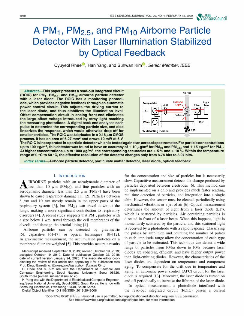
Fig. 2. Timing diagram of the LD-PM detector.
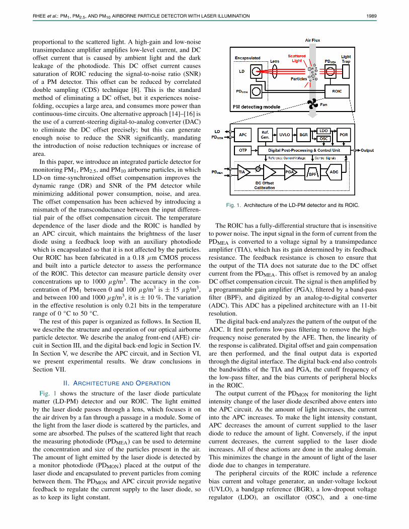
Fig. 3. (a) The analog front-end and operation of DC offset compensation and (b) problem of constant DC offset compensation.
programmable memory (OTP). The lockout circuit blocks theBGR start signal unless the supply voltage reaches a thresholdto avoid unexpected behavior. The BGR and LDO receive anexternal supply voltage of 5 V and generate an analog supplyvoltage of 4.4 V and a digital supply voltage of 1.8V. Thepower-on reset (POR) outputs a reset signal which sets theinitial value of the registers in digital when the supply voltageis applied. The initial values are stored in the one-timeprogrammable memory. The stored values compensate forprocess variations. The timing of the LD-PM detector is shownin Fig. 2. The lifetime of a laser diode is inversely proportional
to the time it is turned on. To increase the lifetime of thedetector, the laser diode, together with the TIA, the offsetcompensation circuit, and the PGA, is turned off.
III. ANALOG FRONT-END CIRCUIT
The analog front-end circuit consists of a TIA, a DCoffset compensation circuit, a PGA, and a high-pass filter(HPF), as shown in Fig. 3(a). Timing is also shown atseveral nodes when the laser diode is on (LD_ON). All ofthese are implemented as fully differential circuits to reducethe effect of power supply noise. The photodiodes have a
RHEE et al.: PM1, PM2.5, AND PM10 AIRBORNE PARTICLE DETECTOR WITH LASER ILLUMINATION 1991
p-type, intrinsic, and n-type (PIN) structure, and responds towavelengths between 400 nm and 1,100 nm. The photocurrentgenerated by the PDMEA is converted into a voltage signalthrough the feedback resistors R1 of the TIA, as shown inFig. 3(a). The transimpedance gain set by R1 can be controlledfrom 30 k� to 5 M�. Feedback capacitor C1, is combinedwith R1 to form a low-pass filter which cuts off the response ata frequency of 1/(2πR1C1). This cutoff frequency of the TIAis set to 4 kHz when R1 is set to 5 M� and C1 is set to 8 pF.
As described in Section I, there is a DC offset in the signalfrom the photodiode, which is much larger than the variationsin voltage produced by the light reflected by particles. This off-set remains in the output from the TIA and potentially reducesthe dynamic range of the ROIC as a whole. Fig. 3(a) shows theproblem that occurs when DC offset is not removed. If the DCoffset is not removed and amplified by the proceeding PGA,signal clipping can occur (red-colored waveform) because thesignal, as well as the DC offset, are amplified. If the gainof the signal-chain is lowered to prevent this signal clipping,the overall SNR and DR are degraded.
The offset compensation has been achieved by introducinga mismatch of the transconductance between the differentialinput pair of the operational amplifier in the DC offsetcompensation circuit. In the DC offset compensation circuit,R2 and R3 are the same, so the following relation holds:
VOUT = −(VIN + VOS,light) + 2VOS,Comp, (1)
where VIN and VOUT are the input and the output of theDC offset compensation circuit respectively. VOS,light is thelight-induced offset and VOS,Comp is the offset compensationvoltage. However, DC offset compensation should only beactivated when the laser diode is on. Fig. 3(b) shows whathappens with constant DC offset compensation (green-coloredwaveform). If the DC offset compensation is applied con-stantly, the DC level of the signal is shifted by 2VOS,Comp. Theoffset resulting from this DC level shift is amplified again bythe following stages. After the HPF and PGA2, signal clippingoccurs at the output of the PGA2, as shown in Fig. 3(b). If off-set compensation is applied when LD_ON is on, the signal isreduced by 2VOS,Comp only when LD_ON is on and no dcshift occurs. Therefore, the DC offset compensation timingneed to be synchronized with the laser diode on/off timing.
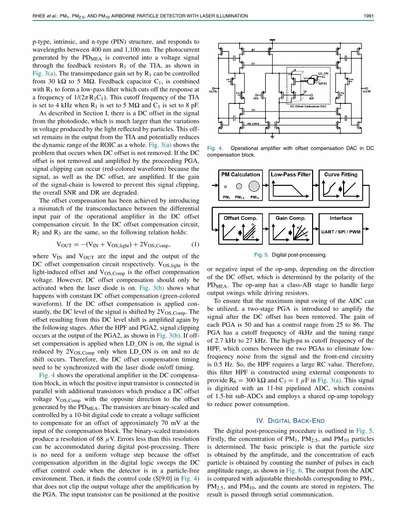
Fig. 4 shows the operational amplifier in the DC compensa-tion block, in which the positive input transistor is connected inparallel with additional transistors which produce a DC offsetvoltage VOS,Comp with the opposite direction to the offsetgenerated by the PDMEA. The transistors are binary-scaled andcontrolled by a 10-bit digital code to create a voltage sufficientto compensate for an offset of approximately 70 mV at theinput of the compensation block. The binary-scaled transistorsproduce a resolution of 68 μV. Errors less than this resolutioncan be accommodated during digital post-processing. Thereis no need for a uniform voltage step because the offsetcompensation algorithm in the digital logic sweeps the DCoffset control code when the detector is in a particle-freeenvironment. Then, it finds the control code (S[9:0] in Fig. 4)that does not clip the output voltage after the amplification bythe PGA. The input transistor can be positioned at the positive
Fig. 4. Operational amplifier with offset compensation DAC in DCcompensation block.
Fig. 5. Digital post-processing.
or negative input of the op-amp, depending on the directionof the DC offset, which is determined by the polarity of thePDMEA. The op-amp has a class-AB stage to handle largeoutput swings while driving resistors.
To ensure that the maximum input swing of the ADC canbe utilized, a two-stage PGA is introduced to amplify thesignal after the DC offset has been removed. The gain ofeach PGA is 50 and has a control range from 25 to 86. ThePGA has a cutoff frequency of 4kHz and the tuning rangeof 2.7 kHz to 27 kHz. The high-pa ss cutoff frequency of theHPF, which comes between the two PGAs to eliminate low-frequency noise from the signal and the front-end circuitryis 0.5 Hz. So, the HPF requires a large RC value. Therefore,this filter HPF is constructed using external components toprovide R6 = 300 k� and C3 = 1 μF in Fig. 3(a). This signalis digitized with an 11-bit pipelined ADC, which consistsof 1.5-bit sub-ADCs and employs a shared op-amp topologyto reduce power consumption.
IV. DIGITAL BACK-END
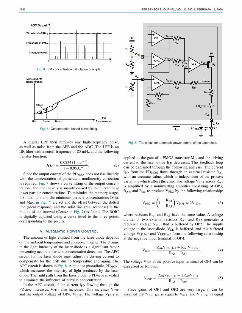
The digital post-processing procedure is outlined in Fig. 5.Firstly, the concentration of PM1, PM2.5, and PM10 particlesis determined. The basic principle is that the particle sizeis obtained by the amplitude, and the concentration of eachparticle is obtained by counting the number of pulses in eachamplitude range, as shown in Fig. 6. The output from the ADCis compared with adjustable thresholds corresponding to PM1,PM2.5, and PM10, and the counts are stored in registers. Theresult is passed through serial communication.
1992 IEEE SENSORS JOURNAL, VOL. 20, NO. 4, FEBRUARY 15, 2020
Fig. 6. PM concentration calculation principle.
Fig. 7. Concentration-based curve fitting.
A digital LPF then removes any high-frequency noise,as well as noise from the AFE and the ADC. The LPF is anIIR filter with a cutoff frequency of 85 mHz and the followingtransfer function:
H (z) = 0.0234(1 + z−1
)1 − 0.953z−1 . (2)
Since the output current of the PDMEA does not rise linearlywith the concentration of particles, a nonlinearity correctionis required. Fig. 7 shows a curve fitting of the output concen-tration. The nonlinearity is mainly caused by the curvature atlower particle concentrations. To minimize the memory usage,the maximum and the minimum particle concentrations (Min.and Max. in Fig. 7) are set and the offset between the dottedline (ideal response) and the solid line (real response) at themiddle of the interval (Center in Fig. 7) is found. The ROICis digitally adjusted using a curve fitted to the three pointscorresponding to the results.
V. AUTOMATIC POWER CONTROL
The amount of light emitted from the laser diode dependson the ambient temperature and component aging. The changein the light intensity of the laser diode is a significant factorpreventing accurate particle concentration detection. The APCcircuit for the laser diode must adjust its driving current tocompensate for the drift due to temperature and aging. TheAPC circuit is shown in Fig. 8. A monitor photodiode, PDMON,which measures the intensity of light produced by the laserdiode. The right path from the laser diode to PDMON is sealedto eliminate the influence of particle concentration.
In the APC circuit, if the current IPD flowing through thePDMON increases, VPD1 also increases. This increases VINPand the output voltage of OP4, VOUT. The voltage VOUT is
Fig. 8. The circuit for automatic power control of the laser diode.
applied to the gate of a PMOS transistor M1, and the drivingcurrent to the laser diode ILD decreases. This feedback loopcan be explained through the following analysis. The currentIPD from the PDMON flows through an external resistor RA3with an accurate value, which is independent of the processvariations which affect the chip. The voltage VPD1 across RA3is amplified by a noninverting amplifier consisting of OP3,RA4, and RA5 to produce VPD2 by the following relationship:
VPD2 =(
1 + RA4
RA5
)VPD1 = 2VPD1, (3)
where resistors RA4 and RA5 have the same value. A voltagedivider of two external resistors RA1 and RA2 generates areference voltage VREF that is buffered by OP2. The supplyvoltage to the laser diode, VLD is buffered, and this bufferedvoltage VLD,buf and VREF,buf form the following relationshipat the negative input terminal of OP4:
VINN = RA6VREF,buf + RA7VLD,buf
RA6 + RA7, (4)
The voltage VINP at the positive input terminal of OP4 can beexpressed as follows:
VINP = RA8VPRELD + 2RA9VPD1
RA8 + RA9. (5)
Since gains of OP1 and OP2 are very large, it can beassumed that VREF,buf is equal to VREF and VLD,buf is equal
RHEE et al.: PM1, PM2.5, AND PM10 AIRBORNE PARTICLE DETECTOR WITH LASER ILLUMINATION 1993
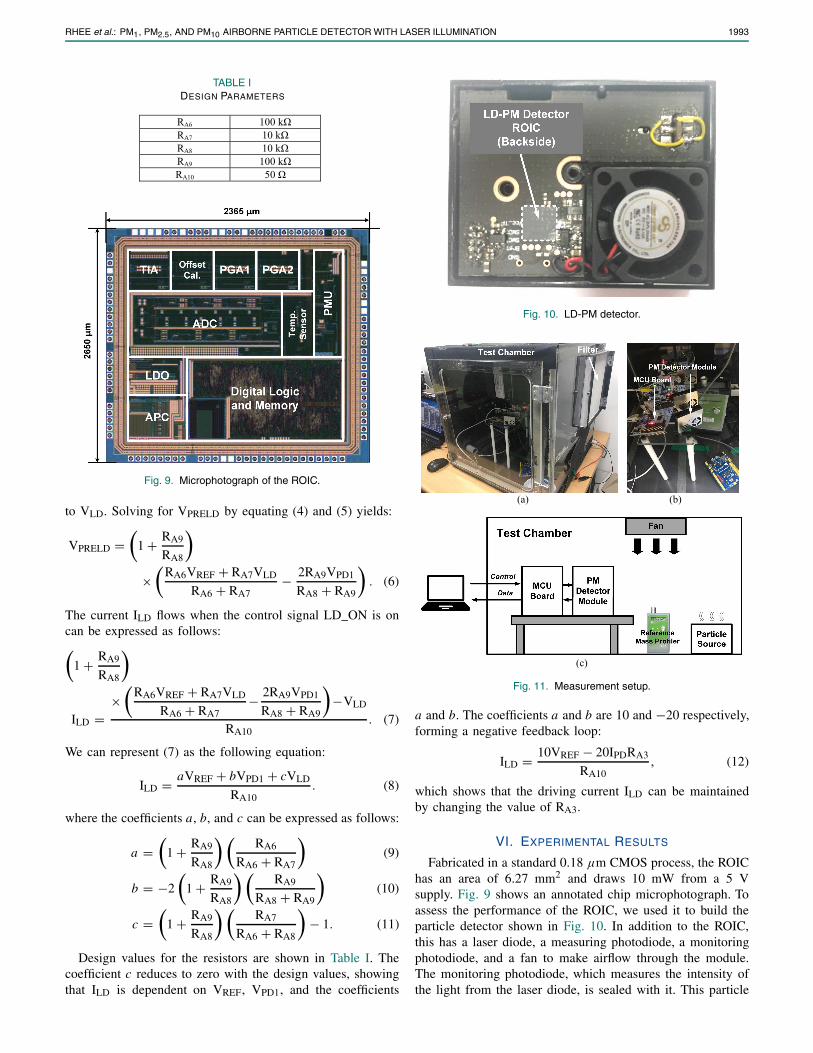
TABLE IDESIGN PARAMETERS
Fig. 9. Microphotograph of the ROIC.
to VLD. Solving for VPRELD by equating (4) and (5) yields:
VPRELD =(
1 + RA9
RA8
)
×(
RA6VREF + RA7VLD
RA6 + RA7− 2RA9VPD1
RA8 + RA9
). (6)
The current ILD flows when the control signal LD_ON is oncan be expressed as follows:(
1 + RA9
RA8
)
ILD =×
(RA6VREF + RA7VLD
RA6 + RA7− 2RA9VPD1
RA8 + RA9
)−VLD
RA10. (7)
We can represent (7) as the following equation:
ILD = aVREF + bVPD1 + cVLD
RA10. (8)
where the coefficients a, b, and c can be expressed as follows:
a =(
1 + RA9
RA8
) (RA6
RA6 + RA7
)(9)
b = −2
(1 + RA9
RA8
) (RA9
RA8 + RA9
)(10)
c =(
1 + RA9
RA8
) (RA7
RA6 + RA8
)− 1. (11)
Design values for the resistors are shown in Table I. Thecoefficient c reduces to zero with the design values, showingthat ILD is dependent on VREF, VPD1, and the coefficients
Fig. 10. LD-PM detector.
Fig. 11. Measurement setup.
a and b. The coefficients a and b are 10 and −20 respectively,forming a negative feedback loop:
ILD = 10VREF − 20IPDRA3
RA10, (12)
which shows that the driving current ILD can be maintainedby changing the value of RA3.
VI. EXPERIMENTAL RESULTS
Fabricated in a standard 0.18 μm CMOS process, the ROIChas an area of 6.27 mm2 and draws 10 mW from a 5 Vsupply. Fig. 9 shows an annotated chip microphotograph. Toassess the performance of the ROIC, we used it to build theparticle detector shown in Fig. 10. In addition to the ROIC,this has a laser diode, a measuring photodiode, a monitoringphotodiode, and a fan to make airflow through the module.The monitoring photodiode, which measures the intensity ofthe light from the laser diode, is sealed with it. This particle
1994 IEEE SENSORS JOURNAL, VOL. 20, NO. 4, FEBRUARY 15, 2020
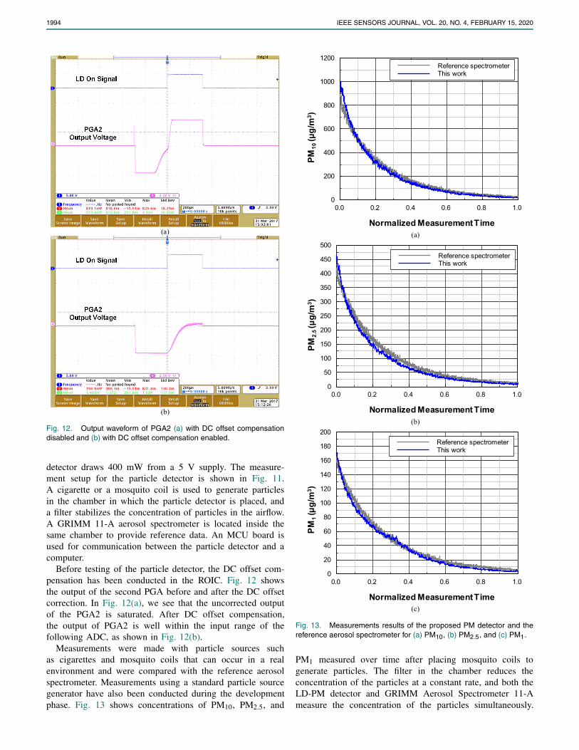
Fig. 12. Output waveform of PGA2 (a) with DC offset compensationdisabled and (b) with DC offset compensation enabled.
detector draws 400 mW from a 5 V supply. The measure-ment setup for the particle detector is shown in Fig. 11.A cigarette or a mosquito coil is used to generate particlesin the chamber in which the particle detector is placed, anda filter stabilizes the concentration of particles in the airflow.A GRIMM 11-A aerosol spectrometer is located inside thesame chamber to provide reference data. An MCU board isused for communication between the particle detector and acomputer.
Before testing of the particle detector, the DC offset com-pensation has been conducted in the ROIC. Fig. 12 showsthe output of the second PGA before and after the DC offsetcorrection. In Fig. 12(a), we see that the uncorrected outputof the PGA2 is saturated. After DC offset compensation,the output of PGA2 is well within the input range of thefollowing ADC, as shown in Fig. 12(b).
Measurements were made with particle sources suchas cigarettes and mosquito coils that can occur in a realenvironment and were compared with the reference aerosolspectrometer. Measurements using a standard particle sourcegenerator have also been conducted during the developmentphase. Fig. 13 shows concentrations of PM10, PM2.5, and
Fig. 13. Measurements results of the proposed PM detector and thereference aerosol spectrometer for (a) PM10, (b) PM2.5, and (c) PM1.
PM1 measured over time after placing mosquito coils togenerate particles. The filter in the chamber reduces theconcentration of the particles at a constant rate, and both theLD-PM detector and GRIMM Aerosol Spectrometer 11-Ameasure the concentration of the particles simultaneously.
RHEE et al.: PM1, PM2.5, AND PM10 AIRBORNE PARTICLE DETECTOR WITH LASER ILLUMINATION 1995
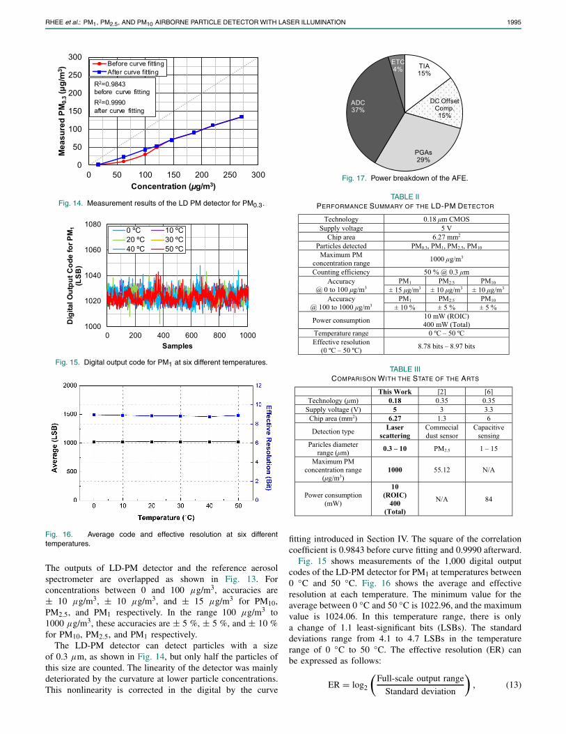
Fig. 14. Measurement results of the LD PM detector for PM0.3.
Fig. 15. Digital output code for PM1 at six different temperatures.
Fig. 16. Average code and effective resolution at six differenttemperatures.
The outputs of LD-PM detector and the reference aerosolspectrometer are overlapped as shown in Fig. 13. Forconcentrations between 0 and 100 μg/m3, accuracies are± 10 μg/m3, ± 10 μg/m3, and ± 15 μg/m3 for PM10,PM2.5, and PM1 respectively. In the range 100 μg/m3 to1000 μg/m3, these accuracies are ± 5 %, ± 5 %, and ± 10 %for PM10, PM2.5, and PM1 respectively.
The LD-PM detector can detect particles with a sizeof 0.3 μm, as shown in Fig. 14, but only half the particles ofthis size are counted. The linearity of the detector was mainlydeteriorated by the curvature at lower particle concentrations.This nonlinearity is corrected in the digital by the curve
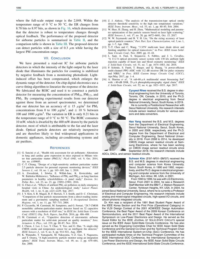
Fig. 17. Power breakdown of the AFE.
TABLE IIPERFORMANCE SUMMARY OF THE LD-PM DETECTOR
TABLE IIICOMPARISON WITH THE STATE OF THE ARTS
fitting introduced in Section IV. The square of the correlationcoefficient is 0.9843 before curve fitting and 0.9990 afterward.
Fig. 15 shows measurements of the 1,000 digital outputcodes of the LD-PM detector for PM1 at temperatures between0 ◦C and 50 ◦C. Fig. 16 shows the average and effectiveresolution at each temperature. The minimum value for theaverage between 0 ◦C and 50 ◦C is 1022.96, and the maximumvalue is 1024.06. In this temperature range, there is onlya change of 1.1 least-significant bits (LSBs). The standarddeviations range from 4.1 to 4.7 LSBs in the temperaturerange of 0 ◦C to 50 ◦C. The effective resolution (ER) canbe expressed as follows:
ER = log2
(Full-scale output range
Standard deviation
), (13)
1996 IEEE SENSORS JOURNAL, VOL. 20, NO. 4, FEBRUARY 15, 2020
where the full-scale output range is the 2,048. Within thetemperature range of 0 ◦C to 50 ◦C, the ER changes from8.78 bits to 8.97 bits, as shown in Fig. 16, which demonstratesthat the detector is robust to temperature changes throughoptical feedback. The performance of the proposed detectorfor airborne particles is summarized in Table II, and thecomparison table is shown in Table III. The proposed detectorcan detect particles with a size of 0.3 μm while having thelargest PM concentration range.
VII. CONCLUSION
We have presented a read-out IC for airborne particledetectors in which the intensity of the light output by the laserdiode that illuminates the particles for counting is stabilizedby negative feedback from a monitoring photodiode. Light-induced offset has been compensated, which enlarges thedynamic range of the detector. On-chip digital electronics use acurve-fitting algorithm to linearize the response of the detector.We fabricated the ROIC and used it to construct a particledetector for measuring the concentration of PM10, PM2.5, andPM1. By comparing experimental results from our detectoragainst those from an aerosol spectrometer, we determinedthat our detector has an accuracy of ± 15 μg/m3 for PM1concentrations from 0 to 100 μg/m3, and ± 10 % between100 and 1000 μg/m3. The variation in ER is only 0.21 bits inthe temperature range of 0 ◦C to 50 ◦C. The ROIC consumes10 mW, which is dwarfed by the 400 mW drawn by the particledetector, most of which is attributable to the fan and the laserdiode. Optical particle detectors are relatively inexpensiveand are therefore likely to find widespread applications indomestic appliances, including air-conditioning systems andair purifiers.
REFERENCES
[1] G. Sancini et al., “Health risk assessment for air pollutants: Alterationsin lung and cardiac gene expression in mice exposed to Milano win-ter fine particulate matter (PM2.5),” PLoS ONE, vol. 9, Oct. 2014,Art. no. e109685.
[2] C.-T. Chiang, “Design of a high-sensitivity ambient particulate matter2.5 particle detector for personal exposure monitoring devices,” IEEESensors J., vol. 18, no. 1, pp. 165–169, Jan. 1, 2018.
[3] A. Zwozdziak, I. Sówka, E. Willak-Janc, K. Kwiecinska, andW. Balinska-Miskiewicz, “Influence of PM1 and PM2.5 on lung functionparameters in healthy schoolchildren—A panel study,” Environ. Sci.Pollut. Res., vol. 23, no. 23, pp. 23892–23901, 2016.
[4] G. Chen et al., “Effects of ambient PM1 air pollution on daily emergencyhospital visits in China: An epidemiological study,” Lancet Planet.Health, vol. 1, no. 6, pp. e221–e229, Sep. 2017.
[5] J. Y. Kim, S. R. Magari, R. F. Herrick, T. J. Smith, and D. C. Christiani,“Comparison of fine particle measurements from a direct-reading instru-ment and a gravimetric sampling method,” J. Occupational Environ.Hygiene, vol. 1, no. 11, pp. 707–715, 2004.
[6] P. Ciccarella, M. Carminati, M. Sampietro, and G. Ferrari, “28.7 CMOSmonolithic airborne-particulate-matter detector based on 32 capacitivesensors with a resolution of 65zF rms,” in IEEE Int. Solid-State CircuitsConf. (ISSCC) Dig. Tech. Papers, Jan./Feb. 2016, pp. 486–488.
[7] M. Carminati et al., “Capacitive detection of micrometric airborneparticulate matter for solid-state personal air quality monitors,” Sens.Actuators A, Phys., vol. 219, pp. 80–87, Nov. 2014.
[8] J. Cheon, J. Lee, I. Lee, Y. Chae, Y. Yoo, and G. Han, “A single-chipCMOS smoke and temperature sensor for an intelligent fire detector,”IEEE Sensors J., vol. 9, no. 8, pp. 914–921, Aug. 2009.
[9] K. Watanabe, T. Yamaguchi, M. Nakayama, Y.-Z. Gao, T. Nagasawa,and T. Ozawa, “A high-sensitivity particle monitor using an integrationsphere,” IEEE Trans. Instrum. Meas., vol. 49, no. 3, pp. 679–684,Jun. 2000.
[10] Z. J. Aleksic, “The analysis of the transmission-type optical smokedetector threshold sensitivity to the high rate temperature variations,”IEEE Trans. Instrum. Meas., vol. 53, no. 1, pp. 80–85, Feb. 2004.
[11] W. Shao, H. Zhang, and H. Zhou, “Mathematical modeling and parame-ter optimization of fine particle sensors based on laser light scattering,”IEEE Sensors J., vol. 17, no. 20, pp. 6672–6681, Oct. 15, 2017.
[12] W. W. Szymanski and B. Y. H. Liu, “On the sizing accuracy of laseroptical particle counters,” Part. Part. Syst. Characterization, vol. 3, no. 1,pp. 1–7, Apr. 1986.
[13] Y.-T. Chen and C. Wang, “3.3/5V multi-rate laser diode driver andlimiting amplifier for optical transceivers,” in Proc. IEEE Asian Solid-State Circuits Conf., Nov. 2005, pp. 41–44.
[14] L. Sant, A. Fant, S. Stojanovic, S. Fabbro, and J. L. Cevallos,“A 13.2 b optical proximity sensor system with 130 klx ambient lightrejection capable of heart rate and blood oximetry monitoring,” IEEEJ. Solid-State Circuits, vol. 51, no. 7, pp. 1674–1683, Jul. 2016.
[15] P. Schönle, S. Fateh, T. Burger, and Q. Huang, “A power-efficientmulti-channel PPG ASIC with 112 dB receiver DR for pulse oximetryand NIRS,” in Proc. IEEE Custom Integr. Circuits Conf. (CICC),Apr./May 2017, pp. 1–4.
[16] A. Sharma et al., “A sub-60-μA multimodal smart biosensing SoCwith >80-dB SNR, 35-μA photoplethysmography signal chain,” IEEEJ. Solid-State Circuits, vol. 52, no. 4, pp. 1021–1033, Apr. 2017.
Cyuyeol Rhee received the B.S. degree in elec-trical engineering from the University of Toronto,Toronto, ON, Canada, in 2010, and the Ph.D.degree in electrical engineering from SeoulNational University, Seoul, South Korea, in 2019.
He is currently a Postdoctoral Researcher withSeoul National University. His research interestsinclude sensor readout circuits for various sen-sors and data converters.
Han Yang received the B.S. and M.S. degreesfrom the Department of Electrical Engineering,Seoul National University, Seoul, South Korea,in 2005 and 2008, respectively, and the Ph.D.degree from the Department of Electrical andComputer Engineering, Seoul National Univer-sity in 2018. From 2008 to 2014, he developedCMOS image sensor readout circuits at Sam-sung Electronics, where he has been workingon CMOS image sensor readout circuits sinceSeptember 2018. His research interests include
ADCs, DACs, and sensor readout circuits.
Suhwan Kim (S’97–M’01–SM’07) received theB.S. and M.S. degrees in electrical engineeringand computer science from Korea University,Seoul, South Korea, in 1990 and 1992, respec-tively, and the Ph.D. degree in electrical engineer-ing and computer science from the University ofMichigan, Ann Arbor, MI, USA, in 2001.
From 1993 to 1999, he was with LG Electronics,Seoul. From 2001 to 2004, he was a ResearchStaff Member with the IBM T. J. Watson ResearchCenter, Yorktown Heights, NY, USA. In 2004, he
joined Seoul National University, Seoul, where he is currently a Professorof Electrical and Computer Engineering. His research interests includeanalog and mixed-signal integrated circuits, high-speed I/O circuits, andsilicon-photonic integrated circuits.
Dr. Kim was a recipient of the 1991 Best Student Paper Award ofthe IEEE Korea Section and the First Prize (Operational Category) inthe VLSI Design Contest of the 2001 ACM/IEEE Design AutomationConference, the Best Paper Award of the 2009 Korean Conference onSemiconductors, and the 2011 Best Paper Award of the InternationalSymposium on Low-Power Electronics and Design. He served as theGuest Editor for the IEEE JOURNAL OF SOLID-STATE CIRCUITS specialissue on the IEEE Asian Solid-State Circuits Conference. He has alsoserved as the Organizing Committee Chair for IEEE Asian Solid StateConference and the General Co-Chair and the Technical Program Chairfor the IEEE International System-on-Chip (SoC) Conference. He hasparticipated multiple times on the Technical Program Committee of theIEEE International SOC Conference, the International Symposium onLow-Power Electronics and Design, the IEEE Asian Solid-State CircuitsConference, and the IEEE International Solid-State Circuits Conference.