.AP ROTORDYNAMIC AND LEAKAGE … · D. W. CHILDS TURBOMACHINERY LABORATORIES MECHANICAL ENGINEERING...
147
AD-A266 012 WL-TR-92-2125 .AP ROTORDYNAMIC AND LEAKAGE CHARACTERISTICS OF A 4-STAGE BRUSH SEAL K. J. CONNER D. W. CHILDS TURBOMACHINERY LABORATORIES MECHANICAL ENGINEERING DEPARTMENT TEXAS A&M UNIVERSITY COLLEGE STATION, TEXAS 77843-3123 6ý Ap R1 9 1993 DECEMBER 1992 FINAL REPORT FOR PERIOD OCTOBER 1988 - AUGUST 1990 APPROVED FOR PUBLIC RELEASE; DISTRIBUTION UNLIMITED "93-08070 AERO PROPULSION & POWER DIRECTORATE .I WRIGHT LABORATORY AIR FORCE MATERIEL COMMAND WRIGHT-PATTERSON AIR FORCE BASE, OHIO 45433-7649
Transcript of .AP ROTORDYNAMIC AND LEAKAGE … · D. W. CHILDS TURBOMACHINERY LABORATORIES MECHANICAL ENGINEERING...

AD-A266 012
WL-TR-92-2125
.AP ROTORDYNAMIC AND LEAKAGE CHARACTERISTICSOF A 4-STAGE BRUSH SEAL
K. J. CONNERD. W. CHILDS
TURBOMACHINERY LABORATORIESMECHANICAL ENGINEERING DEPARTMENTTEXAS A&M UNIVERSITYCOLLEGE STATION, TEXAS 77843-3123 6ý Ap R1 9 1993
DECEMBER 1992
FINAL REPORT FOR PERIOD OCTOBER 1988 - AUGUST 1990
APPROVED FOR PUBLIC RELEASE; DISTRIBUTION UNLIMITED
"93-08070
AERO PROPULSION & POWER DIRECTORATE .IWRIGHT LABORATORYAIR FORCE MATERIEL COMMANDWRIGHT-PATTERSON AIR FORCE BASE, OHIO 45433-7649

NOTICE
When Government drawings, specifications, or other data are used for
any purpose other than in connection with a definitely Government-related
procurement, the United States Government incurs no responsibility or any
obligation whatsoever. The fact that the government may have formulated or
in any way supplied the said drawings, specifications, or other data, is not
to be regarded by implication, or otherwise in any manner construed, as
licensing the holder, or any other person or corporation; or as conveying
any rights or permission to manufacture, use, or sell any patented invention
that may in any way be related thereto.
This report is releasable to the National Technical Information Service
(NTIS). At NTIS, it will be available to the general public, including
foreign nations.
This technical report has been reviewed and is approved for publica-
tion.
C .. .... . ...CONSTANCE A. DOLWER, Capt, USAF MARVIN A. STIBICHProject Engineer, Compressor Research Chief, Compressor Research Section
Technology Branch Technology BranchTurbine Engine Division Turbine Engine DivisionAero Propulsion & Power Directorate Aero Propulsion & Power Directorate
RICHARD J. Hrth1Acting Deputy for TechnologyTurbine Engine DivisionAero Propulsion & Power Directorate
If your address has changed, if you wish to be removed from our mailing
list, or if the addressee is no longer employed by your organization please
notify WL/POTX , WPAFB, OR 45433- 7649 to help us maintain a currentmailing list.
Copies of this report should not be returned unless return is required by
security considerations, contractual obligations, or notice on a specificdocument.

REPORT DOCUMENTATION PAGE oM_ ft. o___ ,__1*1k ronn udnorttcistoof.forfmAtlOu ft .,tMM"~ to ovwp" I hour p1r re-~rteem. j"tdudfn Uth twfe for te,.e.ing sn~ttWUrtoM urarchritq expo"n dot* fiorcn.
geuln nd madnimnq th a neNd. n �e�e�mg .dp ,wwwq the C~ #06ou4 rite~ Jtn d conmmit rarrdýg tnhbkrdei ftt*ett Or ~ "Po n e Ot-- of 3thlalegnOf Inform tion nuin tgeufn o redud t brn.tWiu on .dranon¶ Sonrwe, Otredoetv for IritarmotiOn OW~twon, *nd Aeoort I IS Wefewn"MOeu lWRY. Suit 1204. Atfrs~gow. V 22202nl1410V.edt h fieo aigmn n wWud",et P ap rt~ fteduttbon t Fojec M 70&4 1114). Wehuflgton, DC Z050 I
1. AGENCY USE ONLY (Leave blank) 12. REPORT DATE 3. REPORT TYPE AND OATES COVERED
DEC 1992 FINAL 10/30/88--08/30/92"4. TITLE AND SUOTrtE ROToRDYNARHIC AND LEAKAGE CHARACTE "X NGNUMSERS
OF A 4-STAGE BRUSH SEAL C F33615-88-C-2908PE 62203PR 3066
S.AUTHORK). 1. CONNER TA 11D. W. CHILDS WU 69
7. PERFORMING ORGANIZATION NAME(S) AND ADORESS(ES) 8. PERFORMING ORGANIZATION
TURBOMACHINERY LABORATORY REPORT NUMBER
MECHANICAL ENGINEERING DEPARTMENTTEXAS A&M UNIVERSITYCOLLEGE STATION TX 77843-3123
9-. 4WD]AM D• • RATE 10. SPONSORING / MONITORING
WRIGHT LABORATORY Wt6q_ -V-O pytS!ER
AIR FORCE MATERIEL COMMANDWL/POTX, Attn: DOWLER 513-2558210
11. SIMMNEORYMR4URRECTED VERS10N OF A FINAL REPORT PREVIOUSLYPUBLISHED AS REPORT WL-TR-91-2013.
121. S ZL ; DISTRIBUTION IS i2b. DISTRIBUTION CODE
UNLIMITED. -f _
Appnrred for pubUc r610=0
13. ABSTRACT (Maximum 200 words)
Experimental results are presented for the direct and cross-coupled stiffness anddamping coefficients as well as the leakage performance for a 4-stage brush seal.Variable test parameters include the inlet pressure, pressure ratio, shaft speed,fluid pre-rotation, and seal spacing. Direct damping is shown to increase withrunning speed; otherwise, the rotordynamic coefficients are relatively insensitiveto changes in the test parameters. Cross-coupled stiffness is generally unchangedby increasing the inlet tangential velocity to the seals, suggesting that the brushseal is not affected by inlet swirl. Direct stiffness is shown to increase withfrequency; however, the magnitudes of direct stiffness are always positive. Cross-coupled stiffness increases slightly with freqt'_ncy; yet not as drastically as directstiffness. Comparisons of test results for the 4-stage brush seal with an 8-cavitylabyrinth showed superior rotordynamics performance for the brush seal; viz., largervalues for direct stiffness and lower values for the (destabilizing) cross-coupledstiffness coefficient. The damping for brush seals is smaller, but comparable tolabyrinth seals. The whirl-frequency ratio is always smaller for the brush seal.
14.-SIIM RAL, ROTORDYNAHICS, SEAL, TURBINE IS. NUMBER OF PACES"147
16. PRICE CODE
17. SECURITY CLASSIFICATION 18. SECURITY CLASSIFICATION 19. SECURITY CLASSIFICATION 20. LIMITATION OF ABSTRACT
NN50l-01-20-SIFIE StndaMdFIED Fm I•98 (!E UL
NSN 7540-01-280-5500 Standard Form 298 (Rev 2-89)Pleirlbed IN~ AN~.! (d IF IQ '

TABLE OF CONTENTS
CHAPTER Page
I INTRODUCTION .................................... 1
Rotordynamic Coefficient Definition .................... 3
II EXPERIMENTAL SETUP .............................. 6
Rotordynamic Coefficient Identification ................ 10
Test Apparatus Modifications ........................ 12
Experimental Uncertainty Analysis .................... 17
III TEST RESULTS ...................................... 25
Test Parameters .................................. 25
Inter-Stage Pressure Profiles ......................... 27
Leakage Characteristics ............................ 33
Direct Stiffness ................................... 46
Cross-Coupled Stiffness ............................. 53
Direct Damping ................................... 57
Whirl-Frequency Ratio ............................. 64
Comparison to a Tooth-on-Rotor Labyrinth Seal .......... 68
Torque Imposed on the Shaft Due to Friction ............ 72
IV CONCLUSIONS ...................................... 74
REFERENCES ....................................... 77
APPENDIX
A Impedance Function Plots ............................... 79
B Tabulation of Test Conditions and Test Results ............... 107
C Tabulation of Rotordynamic Coefficients and the expectedU ncertainties ......................................... 117
iii

LIST OF FIGURES
Page
Figure 1 - Axial and cross-section views of a brush seal ................. 2
Figure 2 - Forces on whirling rotor . ............................... 4
Figure 3 - Air seal test apparatus .................................. 7
Figure 4 - Front detail of test rig showing hydraulic shaker unit ........... 8
Figure 5 - Support and position of the seal stator within the test housing ... 9
Figure 6 - Cross section of test rig . ............................... 12
Figure 7 - Cross-section detail of seal stator.......................... 13
Figure 8 - Maximum and intermediate swirl vanes ..................... 16
Figure 9 - Time and Frequency traces of Fx, Fy, and X ................. 22
Figure 10 - Scatter comparison of direct and cross-coupled damping data ... 24
Figure 11 - Seal configurations . .................................. 26
Figure 12- Pressure distribution for seal 2 with no inlet swirl ............. 29
Figure 13 - Pressure distribution for seal 2 with intermediate swirl ......... 30
Figure 14 - Pressure distribution for seal 2 with high inlet swirl ............ 31
Figure 15 - Pressure distribution for seal 3 with no inlet swirl ............. 32
Figure 16 - Pressure distribution for seal 3 with intermediate swirl ......... 33
Figure 17 - Pressure distribution for seal 3 with high swirl ............... 34
Figure 18 - Delta P across each stage with no inlet swirl for seal 3 ......... 35
Figure 19 - Delta P across each stage with intermediate inlet swirl for seal3. ................................................... 36
Figure 20 - Delta P across each stage with high inlet swirl for seal 3 ........ 37
Figure 21 - Inlet tangential velocity vs. inlet pressure and rotor speed for seal1. ................................................... 39
Figure 22 - Inlet tangential velocity vs. inlet pressure and rotor speed for seal2. . ... ............................................ 40
Figure 23 - Inlet tangential velocity vs. inlet pressure and rotor speed for seal3 . ....................................... ............ 41
Figure 24 - Mass flow rate vs. inlet circumferential velocity ratio for seal 1... 42
Figure 25 - Mass Flow rate vs. inlet circumferential velocity ratio for seal 2. 43
iv

viii
Page
Figure 45 - Leakage rate comparison between a 4-stage brush seal and a 9-cavity tooth-on-rotor labyrinth seal ............................ 69
Figure 46 , Direct stiffness comparison between laby-inth and brush seals... 69
Figure 47 - Cross-coupled stiffness comparison for labyrinth and brush seals.. 70
Figure 48 - Direct damping comparison for labyrinth and brush seals ....... 71
Figure 49 - Whirl frequency compariscn for labyrinth and brush seals ...... 71
Figure 50 - Time traces of the load cell output in volts .................. 73
Figure 51 - Direct stiffness impedance graph for seal 1 with no fluid pre-rotation. .............................................. 80
Figure 52 - Direct stiffness impedance graph for seal 1 with intermediate fluidpre-rotation. ........................................... 81
Figure 53 - Direct stiffness impedance graph for seal 1 with high fluid pre-rotation . .............................................. 82
Figure 54 - Cross-coupled stiffness impedance graph for seal 1 with no fluidpre-rotation. ........................................... 83
Figure. 55 - Cross-coupled stiffness impedance graph for seal 1 withintermediate fluid pre-rotation ............................... 84
Figure 56 - Cross-coupled stiffness impedance graph for seal 1 with high fluidpre-rotation. ........................................... 85
Figure 57 - Direct damping impedance graph for seal 1 with no fluid pre-rotation ............................................... 86
Figure 58 - Direct damping impedance graph for seal 1 with intermediate fluidpre-rotation. ........................................... 87
Figure 59 - Direct damping impedance graph for seal 1 with high fluid pre-rotation. .............................................. 88
Figure 60 - Direct stiffness impedance graph for seal 2 with no fluid pre-rotation. .............................................. 89
Figure 61 - Direct stiffness impedance graph for seal 2 with intermediate fluidpre-rotation . ........................................... 90
Figure 62 - Direct stiffness impedance graph for seal 2 with high fluid pre-rotation . .............................................. 91
Figure 63 - Cross-coupled stiffness impedance graph for seal 2 with no fluidpre-rotation. ........................................... 92
Figure 64 - Cross-coupled stiffness impedance graph for seal 2 withintermediate fluidpre-rotation ............................... 93
vi

Page
Figure 26 - Mass flow rate vs. inlet circumferential velocity ratio for seal 3... 44
Figure 27 - Mass flow rate vs. inlet pressure .......................... 45
Figure 28 - Direct stiffness as a function of frequency ................... 48
Figure 29 - Intercept of Re(P/X) vs. inlet velocity ratio .................. 49
Figure 30 - Mean value of K vs. inlet circumferential velocity ratio for seal1 . ................................................... 50
Figure 31 - Mean value of K vs. inlet circumferential velocity ratio for seal2 . ................................................... 51
Figure 32 - Mean value of K vs. inlet circumferential velocity ratio for seal3 . ................................................... 52
Figure 33 - Cross-coupled stiffness versus inlet circumferential velocity ratiofor seal 1 . ............................................. 54
Figure 34 - Cross-coupled stiffness versus inlet circumferential velocity ratiofor seal 2 . ............................................. 55
Figure 35 - Cross-coupled stiffness versus inlet circumferential velocity ratiofor seal 3 . ..................................... ....... 56
Figure 36 - Direct damping versus inlet circumferential velocity ratio for seal1 . ................................................... 58
Figure 37 - Direct damping versus inlet circumferential velocity ratio for seal2 . ................................................... 59
Figure 38 - Direct damping versus inlet circumferential velocity ratio for seal3. .................................................... 60
Figure 39 - Im(ix/X) intercept at w =0 versus inlet circumferential velocityratio for seal 1 .......................................... 61
Figure 40 - Im(Fx/X intercept at w =0 versus inlet circumferential velocityratio for se l 2 , ......................................... 62
Figure 41 - lm(Fx/X) intercept at -=-0 versus inlet circumferential velocityratio for seal 3.......................................... 63
Figure 42 - Whirl frequency ratio versus inlet circumferential velocity ratio forseal 1 . ................................................ 65
Figure 43 - Whirl frequency ratio versus inlet circumferential velocity ratio forseal 2 . ................................................ 66
Figure 44 - Whirl frequency ratio versus inlet circumferential velocity ratio forseal3 . ................................................ 67
-- • ia i IIV

LIST OF TABLES
Page
Table I - Test parameters ................................. ..... 26
Table 2 - Rotor growth as a function of speed ....................... 27
Table B1 - Static and dynamic test data for seal 1 cases with no fluid pre-rotation. ............................................. 108
Table B2 - Static and dynamic test data for seal 1 cases with intermediate fluidpre-rotation . .......................................... 109
Table B3 - Static and dynamic test data for seal 1 cases with high fluid pre-rotation. ............................................. 110
Table B4 - Static and dynamic test data for seal 2 cases with no fluid pre-rotation . ............................................. 111
Table B5 - Static and dynamic test data for seal 2 cases with intermediate fluidpre-rotation. .......................................... 112
Table B6 - Static and dynamic test data for seal 2 cases with high fluid pre-rotation . ............................................. 113
Table B7 - Static and dynamic test data for seal 3 cases with no fluid pre-rotation. ............................................. 114
Table B8 - Static and dynamic test data for seal 3 cases with intermediate fluidpre-rotation . .......................................... 115
Table B9 - Static and dynamic test data for seal 3 cases with high fluid pre-rotation . ............................................. 116
Table Cla - Rotordynamic coefficient test data and uncertainties for seal 1cases with no fluid pre-rotation ............................. 117
Table CIb - Static and dynamic test data for seal 1 cases with no fluid pre-rotation. ............................................. 118
Table C2a - Rotordynamic coefficient test data and uncertainties for seal 1cases with intermediate fluid pre-rotation ...................... 119
Table C2b - Static and dynamic test data for seal 1 cases with intermediatefluid pre-rotation ....................................... 120
Table C3a - Rotordynamic coefficient test data and uncertainties for seal 1cases with high fluid pre-rotation. ......................... 121
Table C3b - Static and dynamic test data for seal 1 cases with high fluid pre-rotation . ............................................. 122
Table C4a - Rotordynamic coefficient test data and uncertainties for seal 2cases with Do fluid pre-rotation. ............................ 123
viii

Page
Figure 65 - Cross-coupled stiffness impedance graph for seal 2 with high fluidpre-rotation . ........................................... 94
Figure 66 - Direct damping impedance graph for seal 2 with no fluid pre-rotation ............................................... 95
Figure 67 - Direct damping impedance graph for seal 2 with intermediate fluidpre-rotation . ........................................... 96
Figure 68 - Direct damping impedance graph for seal 2 with high fluid pre-rotation . .............................................. 97
Figure 69 - Direct stiffness impedance graph for seal 3 with no fluid pre-rotation. .............................................. 98
Figure 70 - Direct stiffness impedance graph for seal 3 with intermediate fluidpre-rotation . ........................................... 99
Figure 71 - Direct stiffness impedance graph for seal 3 with high fluid pre-rotation . ............................................. 100
Figure 72 - Cross-coupled stiffness impedance graph for seal 3 with no fluidpre-rotation . .......................................... 101
Figure, 73 - Cross-coupled stiffness impedance graph for seal 3 withintermediate fluid pre-rotation .............................. 102
Figure 74 - Cross-coupled stiffness impedance graph for seal 3 with high fluidpre-rotation ............................................ 103
Figure 75 - Direct damping impedance graph for seal 3 with no fluid pre-rotation . ............................................. 104
Figure 76 - Direct damping imDedance graph for seal 3 with intermediate fluidpre-rotation ........................................... . 105
Figure 77 - Direct damping impedance graph for seal 3 with high fluid pre-rotation . ............................................. 106
vii
NOMENCLATURE
C, c Direct and cross-coupled damping coefficients.
CPM Shaft angular velocity (cycles/minute).
6 (x) Uncertainty of variable x.
f=k/Oo Whirl frequency ratio.
FRx, FRY Reaction forces, equation (1).
Fx, Fy Fluid forces imposed on the seal.
lx, F, Complex fluid forces imposed on the seal.
M Stator mass.
rm Mass flow rate (kg/s).
W Frequency.
K, k Direct and cross-coupled stiffness coefficients. -NTI•
PO Inlet stagnation pressure.
Pb Exit stagnation pressure. I ..
Pla,, XStagnation pressure in cavity 1, 2, or 3.
SEE Standard error of estimate.
U Inlet circumferential velocity (m/s). , .
Uo Inlet circumferential velocity ratio.
wf Total uncertainty in a result, f.
X, Y Position coordinates of the rotor relative to the stator.
Sr, i

PageTable C4b - Static and dvr---,c test data for seal 2 cases with no fluid pre-
rotation ....... ...................................... 124
Table C5a - Rotordynamic coefficient test data and uncertainties for seal 2cases with intermediate fluid pre-rotation. ................... . 125
Table C5b - Static and dynamic test data for seal 2 cases with intermediate.Ad pre-rotation . ...................................... 126
Table C6a - Rotordvnamic coefficient test data and uncertainties for seal 2cases with high fluid pre-rotation ............................ 127
Table C6b - Static and dynamic test data for seal 2 cases with high fluid pre-rotation . .............................................. 128
Table C7a - Rotordynamnic coefficient test data and uncertainties for seal 3cases with no"fluid pre-rotation ............................. 129
Table C7b - Static and dynamic test data for seal 3 cases with no fluid pre-rotation . ............................................. 130
Table CSa - Rotordynamic coefficient test data and uncertainties for seal 3cases with intermediate fluid pre-rotation ...................... .31
Table C8b - Static and dynamic test data for seal 3 cases with intermediatefluid pre-rotatiom ...................................... 132
Table C9a - Rotordvnamic coefficient test data and uncertainties for seal 3cases with high fluid pre-rotation ............................ 133
Table C9b - Static and dynamic test data for seal 3 cases with high fluid pre-rotation . ............................................. 134
i x

NOMENCLATURE
C, c Direct and cross-coupled damping coefficients.
CPM Shaft angular velocity (cycles/minute).
6 (x) Uncertainty of variable x.
f=k/Ci Whirl frequency ratio.
FRx, FRy Reaction forces, equation (1).
Fx, Fy Fluid forces imposed on the seal.
Fx, Fy Complex fluid forces imposed on the seal.
M Stator mass.
m Mass flow rate (kg/F).
W Frequency.
K, k Direct and cross-coupled stiffness coefficients.
Po Inlet stagnation pressure.
Pb Exit stagnation pressure.
P11., X Stagnation pressure in cavity 1, 2, or 3.
SEE Standard error of estimate.
U90 Inlet circumferential velocity (m/s).
%0 Inlet circumferential velocity ratio.
Wr Total uncertainty in a result, f.
X, Y Position coordinates of the rotor relative to the stator.
Xi

CHAPTER 1
INTRODUCTION
Current designs for high performance turbomachinery require higher pressures,
temperatures, and rotational speeds. This trend has caused almost universal use of
labyrinth seals due to the low leakage performance in comparison to other seals.
Some seals, however, cause a rotordynamic instability in the shaft. Instability is
caused by a driving force in the tangential direction of a whirling rotor. This force
has been proven to be caused by tangential fluid flow induced in labyrinth and similar
seals. Therefore, more research and development into different types of seals using
current state-of-the-art technology is being done on a continuing basis.
An alternative to labyrinth P- i similar seals is the brush seal. Figure 1 is a
drawing of a brush seal in cross-section and axial views. This seal consists of a front
and back plate, with wire bristles sandwiched in-between. The bristles point radially
inward and contact the shaft at an angle. The internal diameter of the seal used in
the present tests is 129.4 mm and the external diameter is 158.7 mm. The seals were
fabricated by Cross Manufacturing Co. The bristle material is inconel X750, and the
side plates are nimonic 75 HR 203.
The journal model for this thesis is the Transactions of the ASME, Journal ofTribology.

W/eld-a
Front plate -- %
Back plate
Bristles
Entarged Section5X
Figure I - Axial and cross-section views of a brush seal.
The rotor is coated with a hard ceramic coating to prevent the bristles from
wearing a groove into the rotor. The coating is machined smooth to prevent erosion
of the bristles. Because the bristles contact the shaft at an angle, the bristles tend to
bend instead of buckle when changes in the relative radial position of the shaft occur.
Ferguson (1988) compares leakage performance of the brush seal to various
five-finned labyrinth seal designs. Comparative data showed that the leakage rates
of the brush seal were dramatically lower, as low as 5% in comparison to a vertical
fin, 0.75 mm clearance labyrinth seal. Braun et al. (1990) have published flow-
2

visualization results in an attempt to explain the flow phenomena involved in the
superior leakage performance of brush seals. Chupp and Nelson (1990) performed
an evaluation of replacing current labyrinth seals with brush seals in limited life
engines. Their results showed that brush seals offer significant sealing improvements
over labyrinth seals. It was also shown that brush seals have an initial wear-in period,
yet retain significantly reduced leakage rates over labyrinth seals for times exceeding
limited-life applications. Holle and Krishnan (1990) have investigated the utilization
of various high temperature brush seals in several test engines. Results indicate that
leakage reductions in comparison to labyrinth seals approach an order of magnitude.
Yet, they have a concern about the application of brush seals is the wear and
durability characteristics on uncoated rotors. They concluded that wear rates are on
the order of hundAXxds of hours, not the thousands of hours desirable for reusable
engines. Flower (1990) has proposed several different designs of brush seals. These
include an abradable back-plate design, a strip seal, which uses metal strips instead
of bristles, and a segmented seal which would aid in maintenance and assembly. To
the author's knowledge, the present work is the first investigation of the rotordynamic
characteristics of brush seals.
Definition of Rotordynamic Coefficients
Previous publications (Childs and Scharrer, 1986, and Scharrer, 19871 have
proven that forces in annular seals can influence the stability of the shaft. The forces
3

on a whirling rotor can be expressed in terms of radial and tangential components as
shown in Figure 2.
Y
/ 1 I/ A
I
\ /\I /
Figure 2 - Forces on a whirling rotor.
The reaction forces arising for an annular seal exhibiting small motion about
the centered position can be modeled as:
{ FRY J [-k K LY 4+C C.lyj
4

Where X and Y define the motion of the rotor relative to the stator, and FRX
and FRy are the reaction forces acting on the rotor. K, k, C, and c are the direct
stiffness, cross-coupled stiffness, direct damping, and cross-coupled damping
coefficients, respectively.
The cross-coupled stiffness k is the source of destabilizing forces in labyrinth
annular seals and arises due to fluid rotation within the seal. This destabilizing effect
is aggravated when the fluid enters the seal with a "swirl" or tangential velocity
component in the direction of rotation. Various investigations (Childs, Baskharone,
and Ramsey, 1990, and Childs and Ramsey, 1990) have demonstrated that k can be
reduced or even reversed if an inlet "swirl brake" is placed upstream of the seal to
reduce or reverse the inlet tangential velocity to the seal.
The nature of a brush seal is such that it would appear to be both a seal and
a swirl brake; i.e., intuitively, the closely packed bristles 3hould reduce or eliminate
the inlet tangential velocity. The present research was motivated by this optimistic
thought and has the objective of measuring rotordynamic coefficients of brush seals.
5

CHAPTER II
EXPERIMENTAL SETUP
The test apparatus and facility used in this study were developed as part of an
extended, joint, NASA-USAF funded research program for annular gas seal research.
J.B. Dressman of the University of Louisville completed the original design of the test
rig in 1982. Several modifications to both the test apparatus and the supporting
facilities have been made since that time. A detailed description of the test facility
and the basic configuration have been discussed in earlier publications [8,9].
The test rig uses air as the fluid medium and can identify the rotordynamic
coefficients of various types of annular gas seals. Figure 3 shows that the high speed
test shaft is suspended in a pendulum fashion from a rigidly mounted pivot shaft.
This configuration allows side-to-side motion of the test shaft for both static
positioning and dynamic excitation. The upper pivot shaft has an eccentric cam which
allows static vertical positioning of the rotor. Figure 4 shows how the rotor is
statically centered and horizontally excited about its center by a hydraulic shaker
head, which acts on the shaft housing against a return spring. Forces encountered by
the seal stator during this excitation are measured by three piezo-electric, tri-axial,
load cells, which support the stator in a trihedral fashion as shown in Figure 5. The
shake frequency is varied using a swept sine wave from 35 to 70 Hz. with an
amplitude of approximately 0.089 mm. Theoretically, the rotordynamic coefficients

-" - d! -' -e + :f
PIVOT SHAFT
S" rTHRUST sEARtSUa
i " ~LOAD CE'LL.
T3 ROTOROO~
oo
Figure 3 -Air seal test apparatus.

PI VOTSHAFT
+
RETURN
SHAKER ROTOR SPRINGHOUSING
Figure 4 - Front detail of test rig showing hydraulic shakerunit.
should be independent of shake frequency. However, previous testing has shown that
the coefficients of some seals depend on frequency. The swept-sine-wave excitation
used here is patterned after the procedure followed by Bolleter et al. (1987).
The excitation lasts for approximately one second during which the gas forces
and rotor position data are taken. After each shake, a two second time interval
allows residual vibration in the system to be damped out and also allows the
computer and data acquisition unit to calculate and record the needed data. Spurious
or random data is reduced by time averaging the response signals over 35 sweeps.
I S

STATOR HOUSING
\Y LOAD CELLSPRESSURE(3EQSPQUILLS
\ • /-ROTOR
ACCELEROMETER(2) PL.
Figure S - Support and position of the seal stator within thetest housing.
The time averaged traces of force and position data are used in the analysis of the
rotordynamic coefficients. A complete discussion of swept sine wave excitation for
modal identification is provided by Ewins (1986).
9

Rotordynaic Coefficient Identification
The rotordynamic coefficients are found experimentally by the following
method. Consider the equations of motion for the brush seal housing:
MIkI= I nI Kk1 X~ C. -c 1 (2)k FRY -k K Y - C C [
In this model, FRx, FRy, X., and Y are the reaction forces and acceleration
components of the stator housing, and M is the mass of the seal stator. The
rotordynamic model defined in equation (2) is simplified because the motion of the
shaft is assumed to be in the horizontal or X direction only; hence, equation (2)
becomes:
{FRX -Mk. } Fx} (K] [+C] (3)FRY - Mk FY -k X -CX 3
The response forces, Fx and Fy, are generated by an analog circuit which sum
FRx and FRy vectorially from the three load cells and subtracts the M X and M Y
terms. The acceleration components are measured by accelerometers positioned as
shown in 5. Proximity probes, which are located 90 degrees apart, are used to
measure the horizontal and vertical position of the rotor, and to measure the position
10

of the rotor during the shake. The data acquisition unit records 1024 data points of
Fx, Fy, and X as a function of time during the 1 second excitation of the rotor. As
mentioned before, the data used for analysis is the time averaged trace of 35
excitations at a set condition of test parameters. The Fourier transform version of
equation (3) is:
x } K + jCw z = ( ,: 14)Fy -k - W Xc zC
where the " symbol indicates the Fourier transform of the variable. The rotordynamic
coefficients are defined as:
K =Re (2) = Re(.~ c = r2 R
6) CP (5 )
k = Re(2) = Re(--) c Im(2) Ii
Only data between 40 and 65 Hz were used in the analysis of the coefficients.
The real and imaginary parts of Z and 1 are plotted with respect to shake frequency.
The average over frequency of Re( Z ) and Re(!) define K and k, and the slope of
Im( Z ) and Im(i) versus frequency define C and c.
11

Test Appar4us Modifications
Recent modifica~ions to the flow field upstream and downstream of the seal
were made in order to accommodate brush seals. A variable length, back-pressure,
labyrinth seal allowed a wider range of available pressure ratios. This back-pressure
seal is internally ported to allow the operator to withdraw or inject air in the gap
between the back-pressure seal and the test seal. Other modifications include a new
rotor, stator, and inlet pre-swirl vanes. Figure 6 is a cross-sectional view of the test
rig which shows these modifications.
PROXIMITY PROBE LOAD CELLBRUSH SEAL STATOR
BACK PRESSURE SEAL- SWIRL VANES,
ROTOR ,--
.,/ //
// ,. F.LO__ ....
S= , F L Gv/
Figure 6 - Cross section of test rig.
The rotor is made of 17-4PH stainless steel and is attached to the test shaft
with a hydraulic taper fit. A ceramic coating was applied to the rotor on the brush
seal surface and machined to a thickness of 0.127 mm., a surface finish of 0.1 Am (4
gin), and a finished diameter of 129.4 mm. This diameter corresponds to the internal
12

diameter of the brush seal, chosen to simulate worn-in conditions. The rotor was
initially coated with chromium carbide, which wore through to the base material after
about 40 hours of testing. A coatings specialist suggested chromium oxide, which is
harder, and has a lower coefficient of friction. This material also has a tendency to
wear smooth, or become smoother as it wears down. This coating performed very
well and showed little wear.
Figure 7 shows how the stator, or seal housing, holds the seals in place via a
retaining ring, which applies an axial pre-load to the seal group.
Brush seatSeC( spacer
- Ret aining ring
/ ,© ©
//O
Pigure 7 Cross-section detail of seal stator.
13
, i /i l I I I

A group of four brush seals was used to create a sufficiently large reaction force to
measure reliably. To test the effect of between-seal spacings, the seals were tested
with no spacer and two different spacer widths. For the two configurations with
spacers between the seals, pressure taps were inserted to measure the axial pressure
distribution. Temperatures were also recorded at the inlet and exit of the test section.
Leakage measurements were performed by a 12.65 mm turbine flow meter.
Modifications were made to the analog circuit used to perform the vector sum
of the X and Y forces to measure the torque imposed on the shaft. The load cells
are positioned such that the shear force measured by the load cells in the tangential
direction would be the force caused by the friction of the bristles. The tangential
force of each load cells are simply recorded as a function of time. In theory, the
three forces could be summed, and multiplied by the radial distance to the load cell
location, with the result being the torque imposed on the seal by the rotation of the
shaft. It will be shown in Chapter 3, however, that torque measurement was not
possible due to equipment limitations.
Inlet swirl of the flow is induced by a set of guide vanes placed in front of the
seal section. These guide vanes are similar in shape to a turbine stator blade. A
computer code developed by NASA was used to generate the blade shape. Previous
research showed that the flow velocities would be very low: therefore, by
aerodynamically contouring the tips of the blades, the vanes were designed with an

inlet-to-exit area ratio of 3 to 1. This desi n reduces the boundary laver effect on the
flow. Two sets of swirl vanes, shown in Figure 8, were designed to provide high and
intermediate tangential velocities.
The high velocity vanes havz an exit angle of 75 degrees and the intermediate
set has an exit angle of 61.8 degrees. The intermediate set provides one half the
tangential velocity of the 75 degree vanes at the same flow rate.
Even though the exit acea of the swirl vanes is small, partial admission had to
be utilized to raise the tange ial velocity due to the extremely low flow rate. Partial
admission was implemented by blocking two out of three blade-to-blade passages, It
is assumed that the rotational velocity component of the flow is conserved and the
losses occur in the axial direction. Using this assumption, the tangential velocity
component of the flow at the inlet to the test seals was predicted in the following
manner. Conservation of momentum is assumed in the tangential direction-, hence,
the tangential velocity component of the flow at the exit of the nozzle equals the
tangent velocity at the inlet to the seal. Viscous losses are also assumed to be low in
the gap between the inlet of the swirl vanes to the inlet of the seal.

Maximum Swirl Vanes
Intermediote Swirl Vanes
Figure 8 - Maximum and intermediate swirl vanes.
' • , , . • I I II I0

The volumetric flow rate, q, is easily computed at the exit of the nozzle,
knowing the measured values of mass flow rate, temperature, and pressure. Dividing
q by the exit area of the nozzle yielded the average magnitude of the exit velocity.
Since the exit angle of the nozzle is known, the tangential component is found by
simple geometry. In order to reduce jetting of the flow into the seal and to allow
mixing of the flow, the guide vanes were placed approximately 6 cm. upstream of the
seal section. Actual tangent velocities depend on the volumetric flow rate. A set of
straight vanes were also tested to provide a benchmark parameter of no fluid pre-
rotation.
Experimental Uncertainty Analysis
All experimentally measured values have a statistical level of uncertainty, which
is comprised of two parts. One part of the total uncertainty is the accuracy
uncertainty, which is the statistical deviation in a group of measured values. The
other type of uncertainty is precision uncertainty, which is the error associated with
the instrument used for the measurement. For example, the diameter of an atom
cannot be measured with a standard ruler because of the precision uncertainty.
Holman (1978) describes a method for calculating a total uncertainty of a parameter
value. This total uncertainty expression is shown in equation (6).1
Wf [(fX1W 12 + (fX 2w2 ) 2 + ... + (fxnWn) 2 -2 (6)
17

where wf is the total uncertainty in a result, f, which is a function of n primary
measurements x1, x2, ... ,x, with uncertainties w1, w2, ... , WA.
To calculate the precision uncertainty values, resolutions for the various
instruments use for measurement have to be identified. The flow meter used to
measure the volumetric flow rate through the seal has a resolution of 0.5% l/s, while
the pressure transducer and thermocouple have resolutions of 0.05% and 0.3 C
respectively. The analog to digital board channels which are used to record the
pressures and temperatures have resolutions of 0.00117 bar and 0.08 C respectively.
The forces on the stator are measured by load cells and accelerometers which have
resolutions of 0.01 N and 0.0001 g's respectively. The force resolution of the
accelerometer is determined by multiplying its resolution by the stator mass, 10.335
kg. The resolution is then found to be 0.103 N. The resolution of the motion probes
are 0.00254 ram.
For quantities such as mass flow rate, temperature, and pressure
measurements, the total uncertainty is found by direct application of the Holman
theory. The rotordynamic coefficients, however, are mathematically calculated from
complex expressions in the frequency domain. This frequency domain expression is
the result of performing a fourier transform on the time domain signals of force in
the X and Y directions, and motion in the X direction. The magnitude of the
accuracy uncertainty in the measured force and motion values result from time
18

averaging 35 separate sweep cycles. Each of the 1024 points of the averaged trace
have a standard deviation associated with it, because each point in the final signal is
the average of that same point in time from 35 separate waves. Experience has
shown that the value of this standard deviation is relatively constant from point to
point on the final wave; therefore, the average of the 1024 standard deviations is used
as a measure of the accuracy uncertainty. Expressions for the total uncertainty in the
direct and cross-coupled stiffness values are:
where:
5K 22
-~ (9)
8k 2 _2 ((10
w r 5K _k 19)8 'k y (10)
]9

Expressions for the total uncertainty in the direct and cross-coupled damping
coefficients are:
[J5_C (t +J (6C 2 (8R 1'
a (C) aIp.~) 6x ) 2+I1~ (6R )2(2
6 (C) rr{ (6C 2 + J48C1 (8k) 2 2 (13)1' 1
where:
6c - 6c _6- 6 -- (14)
8c - (15)
6c
6 P - (16)
The above equations are complex and in the frequency domain. The values
of the accuracy and precision uncertainty which are known in the time domain had
to be correctly transformed to the frequency domain. This had to be done because
the magnitude of the value is mathematically attenuated as a function of the fast
Fourier transform, and the fast swept sine wave mathematics. A detailed description
of the mathematics of the fast swept sine wave is presented by White and Pennington
20

(1982). For example, the motion probes have a resolution of 0.00254 mm (.1 mil), and
the amplitude of the motion trace is on the order of 0.05 mm (2.0 mils) peak to peak,
which is a 5.0% error. Figure 9 shows that the amplitude of motion observed in the
frequency domain has a magnitude of 0.006 mm (.24 mils). Naturally, no energy has
been lost in the mathematics, but the magnitudes of the values have been changed.
Therefore, the values of the accuracy and precision uncertainty for each point are
mathematically attenuated in the same manner as the wave form in question. This
allows meaningful application of the Holman theory in the frequency domain.
Appendix A contains the impedance plots which graphically show the data from which
the rotordynamic coefficients are formed. The accuracy uncertainty is obtained from
the data by applying an expression from Holman [11, 121:
o(Yi - y,,)2 (17)oy •=2n - 1
Where y. is the value of the coefficient in question and y1 are the values of the
coefficient at a given frequency in the range from 40 to 65 Hz.
Another measure of the accuracy uncertainty for the damping coefficients is
the amount of scatter of the data about the defined line given by the regression
analysis. Coleman and Steele (1989) formed a statistic called the standard error of
estimate (SEE):
21

0
4-)
E-4
r-r-r-r.3 - 0 r3 rII- T I I I- T0 0 0 0
(slA 3U-SNOY1 ZAR (gum)~Y X SE1JLWYR
PZ4
224~

[EY -(aXi b) 12 2(18)
SE- N 2
This has the general form of a precision index and is a measure of the scatter
ot the data points about the linear curve fit. The 2 subtracted from N in the
denominator arises because two degrees of freedom are lost from the set of N data
pairs (X.,Yi) when the curve fit constants a and b are determined by the regression
analysis. Schenck (1979) states that a +/-2(SEE) band will contain approximately
95% of the data points. Appendix C contains the SEE values for the direct and cross-
coupled damping values. This statistic has the units of force over displacement, or
in the case of the line from which damping is determined, N/mm (Damping has units
of N-s/mm, which is the slope of the line).
Figure 10 compares the scatter in the direct and cross-coupled damping data.
Cross-coupled damping SEE values are very high, which indicates that there is a large
scatter in the data. The magnitudes of the Im(Fy/X) are low and very scattered in
comparison. All cross-coupled damping data show this behavior; therefore none of
the cross-coupled damping data is presented in graphical form. The graphs which
represent the slope for direct damping show approximate magnitudes of Im(Fx/X)
between 25 and 75 N/mm. The SEE value for the direct damping case is
23

30--
to-40 Slope =c0.2
•,-,o • •Slope = c
30 40 So 80 70 0
Frequency (Hz)
Figure 10 - Scatter comparison of direct and cross-coupleddamping data.
approximately 20-30% of the Im(Fx/X) magnitude. Although this is rather high, the
trend of the data can still be shown with some accuracy. Therefore, direct damping
for all cases tested will be presented in graphical form.
24

CHAPTER III
TEST RESULTS
Test data were taken for three different seal spacings. As mentioned in
Chapter II, four brush seals were used to obtain large enough forces for rotordynamic
coefficient analysis. A listing of the data is tabulated in Appendices A and B.
The test program was carried out to determine the leakage and rotordynamic
characteristics of brush seals and ascertain whether these characteristics are affected
by inlet swirl, inlet pressure, pressure ratio, rotor speed, or seal spacing. Torque
imposed on the rotor by friction of the bristles riding on the shaft surface is also
investigated.
Test Parameters
Rotational speed, inlet pressure, pressure ratio, and fluid pre-rotation are the
four independent test parameters varied on the test apparatus. Three seal
configurations, each having a different inter-stage seal spacer, were tested separately.
The order of testing was seal 2, seal 1, then seal 3. This order of testing will
determine whether effects from one spacer configuration to the next are from wear
or from the spacers placed between the seal stages. Figure 11 shows the seal
configurations and defines the seal notation which will be used throughout the thesis.
25

Seat I - no spocer Seat 2 - 3.18 mm spacer Seat 3 - 6.35 mm spocer
Figure 11 - Sea] configurations.
Speed of the rotor is controlled by a 100 Hp electric variable speed motor and
a synchronous belt drive system. The maximum speed of the test shaft is presently
16000 cpm. Inlet pressure is regulated by a control valve located upstream of the test
section. The pressure ratio is defined by the exit pressure divided by the inlet
pressure. The variation in the exit pressure, fluid pre-rotation, and inter-stage spacing
have been discussed in Chapter II. The results are plotted as a function of the inlet
circumferential velocity ratio, defined as the tangential velocity of the flow divided by
the surface speed of the rotor. Values for the five test parameters are listed in
Table 1.
Table 1 - Test parameters.
Speed Po PRA'no Swirl
(cpm) (bar) (bar) (-)
1-5,000 1 - 7.9 1 -0.55 1 - None
2-12,000 2- 13.1 2-0.40 2 - Int.
3- 16,000 3- 18.3 3-0.25 3 - High
4 - 0.14
26

The notation within Table 1 is used throughout the presentation of the data. The
ceramic-coated test rotor is machined to the same specification as the internal
diameter of the seal, simulating worn-in conditions. However, due to inertial and
thermal effects, the rotor diameter increases as a function of speed. Table 2 shows
the radial growth of the rotor with rotor speed.
Table 2 - Rotor growth as a function of speed.
Rotor Speed Radial Rotor Growth(cpm) (mm)
5,000 0.0037
12,0"', 0.0211
1V ,jO 0.0396
Previous seal data obtained from this test apparatus has been normalized using
the seal radial clearance for comparison purposes. Since the brush seals have zero
radial clearances, no normalized coefficients are presented here.
Inter-Stage Pressure Profiles
For seals 2 and 3, pressure quills were inserted through the spacer to allow
measurement of the cavity pressure by a pressure transducer. Figures 12 through 17
gives the inlet, exit, and cavity pressures as a function of the axial position, speed,
inlet pressure, and pressure ratio. Figures 12, 13, and 14 show the pressure
distribution for seal number 2 for the zero, intermediate, and high fluid pre-ro:ation
2 7

respectively, while Figures 15, 16, and 17 present the pressure distributions for seal
3. Appendix B contains the tabulated cavity pressure and related test conditions for
seals 2 and 3. From these figures, the pressure distribution appears to be virtually the
same for the three fluid pre-rotation cases tested. For the case of no fluid pre-
rotation, seal 2 at 5000 cpm shows that most of the pressure drop is across the last
stage of the seal. Note that this is the first point tested in the test program. Seal 3
also shows this trend, but not to the same degree; therefore, this trend could
disappear as the seals wear into place. Figures 18, 19, and 20 are graphs of delta P
across each stage versus speed, inlet pressure, and pressure ratio with no swirl,
intermediate swirl, and high inlet swirl, respectively. The data shown is for seal 3,
which is the last seal tested in the test program, and is, therefore, representative of
the worn-in conditions. In general, the last stage of the seal group encounters a
slightly higher pressure drop at the lower inlet pressures. As the speed and inlet
pressure increases, the level of delta P across the seal stages become approximately
the same. An explanation of this phenomena could be due to a formation of a shear
layer of fluid between the rotor and bristles at higher speeds and densities. At higher
inlet pressures, the bristles would tend to bend axially towards the low pressure side.
This would cause a fluid film to easily develop. The film would also develop at
higher rotational speeds. This hypothesis is supported by all of the rotordynamic and
leakage data recorded; i.e., all of the data at the lowest inlet pressure and rotor speed
is sporadic.

RPM: 5000 12000 1600020.00
PRESSURE RATIOS1 = .55 2 ..40
16.00 3 = .25 4. = 4
.• 12.00
8.00
-. ' t " ' I I I I | I - ' I | I I $ i t | ' ' '40.00
10.00
L . 1.- 8.00
LW
0.00 t I I
kv 20,00
14.00
02.00 --
06.00 -
4.00
I.I
0.00
o Io I I I I tI I • I - I i F ] I 1 I '
0.0 0.2 0.4 0.8 0.0 1.0 0.0 0.2 0.4 0.6 0.8 1.0 0.0 0.2 0.4 GA. 0.8 1.0
Relative Position of Seal
Figure 12 - Pressure distribution for seal 2 with no inlet swirl.
29

RPM: 5000 12000 1600020.00
PRESSURE RATIOS1 = .55 2 = .40
18.00 -3 .25 4 a .14
,o 12.00
8.00
4.00
0,00 I II (I II II I I - 1 ""IlI ItI I tI Ii I IiI iI
12.00
4.00
20.00
18.00
12.00
8.00
4.00
, 0.00 -" I I I I I I l I I I I ' I I I I I I I "1 f' "
0.0 0.2 0.4 0.6 0.8 1.0 0.0 0.2 0.4 0.6 0.0 1.0 0.0 0.2 0.4 0.6 0.8 2.0
Relative Position of Seal
Figure 13 - Pressure distribution for seal 2 with intermediate swirl.
30_

RPM: 5000 12000 18000
20.00
PRESSURE RATIOSI .55 2 = .40
16o00 3 .25 4 .14
2 132.00
5.0
4.00
20.0
15,00
54.00
4.00
0.0 0 " 1" 1 I I I I I I I I I I I I I I f I I I-
D.w
20.00
16.00 -
'o 12.00 -
8.00 -
CL:
4.00
0.0 0.2 0.4 0.6 0.8 1.0 0.0 0.2 0.4 0.8 0.8 1.0 0.0 0.2 0.4 0.6 0.8 1.0
Relative Position of Seal
Figure 14 - Pressure distribution for seal 2 with high inlet swirl.
3 I

RPM: 5000 12000 1800020.00
PRESVURE RATIOSI = .5 2 = .40
16.00 3 - .25 4 - .14
6..,
A 12.00
8.00
4.00
0.00 j - _-O0 7I- --- 1
20, .:.00 --
S" 18.00 -LI 12.00
.--4) 8.00
(U 4.00
P.
0 .0 0 - f t I" 1' ! '' I 1 '"l I J I I I '' I I I I I I I
cc 20.00-,•
16.00
,A 12.00
6.00
4.00
0.00-- I I - I "1 I0.0 0.2 0.4 0.6 0.8 1.0 0.0 o. 0.4 0.6 0.8 1.0 0.0 02 0.4 0.6 0.8 1.0
Relative Position of Seal
Figure 15 - Pressure distribution for seal 3 with no inlet swirl.
32

RPM: 5000 12000 1600020.00
PRESSR PATIOS1 = .53 2 -. 401 6 . 900 - 3 , .2 5 4 = .1 4
.0 12.00
aaa8.00
4.00
0. I 1"1 1 I I I I I I I l" I I' I 'i I I e 1 I I
12.00
U) -+ 5.00
m4.00
40.0
1zi 20.00 -
16.00 -
" " 12.00 -
8.00 -
4.00
0.0- 1 i11ii ,,,,11 ,,1 1 i11 11 i1 iI - __""i __1 __I ___ __
0.0 0.2 0.4 0.6 o.6 1.0 0.0 0.2 0.4 0.6 0.0 1.0 0.0 0.2 0.4 0.6 0.8 1.0
Relative Position of Seal
Figure 16 - Pressure distribution for seal 3 with intermediate swirl.
33

RPM: 5000 12000 1600020.00
PRESSURE RATIOS1 = .56 2 - .40
18.00 = .25 4 .14
.~12.00
8.00
4.00
.. • ~0.00-f I I 1I I I 'Il 1 "1
20.00
16.00
a 12.00
0) 8.00
4.00
C.)
0.0 0.2 0.4 0.6 0.8 1,0 0.0 0.2 0.4 0.6 0.6 1.0 0.0 0.2 0.4 0.6 0.6 1.0
Relative Position of Seal
Figure 17 - Pressure distribution for seal 3 with high swirl.
34
"0.00 I l I l,

RPM: 5000 12000 16000
PPRESSURE RATIOS7.00 1 = .55 2 = .40
3 = .25 4 - .14
2,00
4.00
0.00-
8.00
7.00a.00
P 7.00
S 6.00C) .
0 1~ 4.00
3.00
o I7.0
2.00
1.00
0.00
V 8.00
4.00
0.0 0.2 0.4 0.6 0.8 ,.0o0.0 0.2 0.4 0.6 0.6 1.0 0.0 0.2 0.4 0.6B 0.6 .0
Relative Position of Seal
Figure 18 - Delta P across each stage with no inlet swirl for seal 3.
5.00
.0 -nIil i i i I I l

RPM: 5000 12000 150008.00
PRESSURE RATIOS7.00 1 = .55 2 = .40
3 = .25 4 = 148.00
.0 5.00
F 4.00
. 3.00
2.00
1.00
S0.00 - I l I I I I• I I I i I I I I I I I" I i 'I "
0 0.00
7.00
4)6.00
5.00
4.. .0
C. ..... ...2 4.00
L, 4OO
oo .. .002.00
7.00
5.00
4.00
3.00
2.00 Z jZZZ1.00
0.00 - I I I
0.0 0.2 0.4 0.6 0.8 1.0 0.0 0.2 0.4 0.6 o.e 1.0 o.o o.2 0.4 o0. o0 1.0
Relative Position of Seal
Figure 19 - Delta P across each stage with intermediate inlet swirl for seal 3.
36

RPM: 5000 12000 160008.00
PRESSUJRE PATIOS7.00 1 .55 2 = .40
3 .254. .146.00
r: 6.00
53.00
0.00 I I 111111"1 I ' 'i
1.00.00
0.00V 6.00
6.00 -
4.00
3.00 -
02.00
AI 1.00
0.00 1
V 8.00
7.00
6,00
4.0
3 .00
2.00
1.00
0.00 -r-T-7-__-__t I r_____
0.0 0.2 0.4 0.6 0.8 1.0 0.0 0.2 0.4 0.6 0.8 1.0 0.0 0.2 0.4 0.6 0.6 1.0
Relative Position of Seal
Figure 20 - Delta P across each stage with high inlet swirl for seal 3.
37

Leakage Characteristics
In the following sections, the mass flow rate and rotordynamic coefficients are
plotted with respect to the i'let circ mferertia! velocity ratio. Uo•/ru. The
calculation of U,, is described in Chapter II. Figures 21, 22, and 23 show the
tangential velocity as a function of both inlet pressure and rotor speed for seals 1, 2,
and 3, respectively.
Figures 24, 25, and 26 show how the mass flow rate increases slightly as the
inlet tangential velocity increases. This increase is more prevalent in seals I and 3,
which were the second and last seal configurations tested. This suggests that this
behavior occurs as the seals wear into place. The mass flow rate also increased in the
order of testing (seal 2, 3, then 1), supporting the arguments made by Chupp and
Nelson [31, and Holle and Krishnan [4]; viz., brush seals require a wear-in period.
Inlet pressure and pressure ratio both influence the mass flow rate. At an inlet
pressure of 7.9 bar, pressure ratio does not have much effect on the flow rate.
However, as inlet pressure increases, the pressure ratio has a greater effect, again
suggesting that the bristles lift off the rotor due to a presence of a shear layer gap at
higher inlet pressures. Figure 27 shows that there is a definite increase of flow rate
with an increase in inlet pressure for all pressure ratios. This is true for all seal
configurations. Rotor speed has no influence on the mass flow rate.
38

CPU 5000 12000 16000
A -4 A24 2 a
12--- f---- -
E0
@11 TP -- IT-TI111I 11111
0 5 10 15 200 10 15 200 5 10 16 20
Inlet Pressure (bar)
Dashed line - High SwirlSolid line = Intermediate Swirl
Pinlet 7.9 bar 13.1 bar 18.3 bar
Cl -
54-
I" 2">N-
@12
0 5 10 i5 20 0 5 10 is 20 0 5 10 15 20
Rotor Speed (cpm)
Figure 21 - Inlet tangential velocity vs. inlet pressure and rotor speed for seal 1.
S13--3-

CPU 5000 12000 16000
IN.
24
4 4
24
122
0 5 10 15 20 0 6 10 15 200 5 10 15 20
Inlet Pressure (bar)
Dashed line = High SwirlSolid line Intermediate Swirl
Pinlet 7.9 bar 13.1 bar 18.3 bar30-
24- U,
E- ,.
°-4) .III• l I •I • I ~ ~ ~ • I'l l ~ •
0 0 15 20 0 5 10 115 lf0 -t 1 1 11101 15 20Rotor Speed (cpm)
Figure 22 - Inlet tangential velocity vs. inlet pressure and rotor speed for seal 2.
4(

CPM 5000 12000 16000,.. 30 -- "
U, I
2--24 - -
I--
0
0e- 111 11111 - -IIill l 1111II111
0 5 10 15 20 0 5 10 15 200 35 10 15 20
Inlet Pressure (bar)
Dashed line - High SwirlSolid line = Intermediate Swirl
Pinlet 7.9 bar 13.1 bar 18.3 barS30--
24 30 _2- 2-... 2
E--S)IS-
-4)
0 5 10 15 go0a 5 10 1s 20. 0 5 10 15 20
Rotor Speed (cpm)
Figure 23 - Inlet tangential velocity vs. inlet pressure and rotor speed for seal 3.
41

RPM: 5000 12000 160000.03
PR~ESSURE RATIOSI1 .55 2 =.403= .25 4 =.14
I.0.02
Ir.:
0.01
0.00 I
0.03 -
.. 0.02
0.01
En
0.00
0.03
42

RPM: 5000 12000 16000
0.03pR&ISURE RATIOSI = .5 2 .403 - .25 4 .14
0.02
I.-
A. 0.01
0.00 I .
0 0.03
0.03
0.01
0.0 J I I' I I
0.03 -
B.
0.02
0.0
0.00 i I 1"1 v l •2 i [ lIf [...I. .. 1
0.0 0.2 0.4 0.8 0.8 0.0 0.2 0.4 0.0 0.2
INLET CIRCUMFERENTIAL VELOCITY RATIO (-)
Figure 25 - Mass Flow rate vs. inlet circumferential velocity ratio for seal 2.
.4 I

RPM: 5000 12000 180000.03
IPRESSMIK RATIOS
3 .- 25 4 14
0.0
0.01
0.03
W. 0.02
0.00
0.0
*0.02
.0.
.. 0.00
0.0 0.2 0.4 0.8 0.8 0.0 0.2 0.4 0.0 0.2
INLET CIRCUMFERENTIAL VELOCITY RATIO(-
Figure 26 - Mass flow rate vs. inlet circumferential velocity ratio for seal 3.
1414

No Swirl Int. Swirl High Swirl0.03
PRESSVRB RATIOS1 = .35 2 = .403 = .2• 4 = .14
0.02
0.0a
I0 0.01 -
0.00 I I I 11 ' I II'11 '1"11 1' ' I I I I I I I I I I I I Il I I l
* 0.03
a 0.02o
- -0.01
0.00 I 111 11111111111M 11111 11111111111MI- 1111111 I i I1 I IIIiiir~r =
0.01 -
0.02 -
0.01 -
0.00 -¶ 111111 11111111
0 5 10 15 20 0 5 10 1s 200 5 10 15 20
Inlet Pressure (bar)
Figure .!7 - Mass flow rate vs. inlet pressure.
45

Direct Stiffness
The model of equation 4 applies for annular, non-contacting gas seals. How
well this model would apply to brush seals was a question to be resolved in the
present study. The mathematical rotordynamic model shown in equation 4 assume
that the stiffness and damping coefficients are independent of excitation frequency,
as is the case for traditional annular seals. However, experimental test results show
that this is not the case for the direct stiffness, K.
Figure 28 is an example of direct stiffness versus excitation frequency. All of
the seal configurations show a direct stiffness which varies linearly with frequency.
Although the slope of this linear relationship remained relatively constant for the two
highest rotor speeds, Figure 29 illustrates the slight drop in the value of the intercept
at w = 0 as the rotor speed increases. This drop is more prevalent and less sporadic
with an increase in inlet pressure. Figures 30, 31, and 32 are the mean values of K
as a function of the inlet velocity ratio. In general, these figures show that as speed
and inlet pressure increase, the dependence of K on pressure ratio decreases, again
suggesting the presence of a shear layer at high surface speeds and inlet pressures.
Seal 3, the last seal tested, showed a slight decrease in K as inlet swirl increases. This
trend is not as prevalent in the data for seals 1 and 2.
i ~ ~ ~ ~ / 6

The reader is reminded that the direct stiffness times radial displacement is a
force in the radial direction, as shown in Figure 2. If the net force in the radial
direction is highly positive or negative, only the natural frequency of the shaft will be
affected, not the rotordynamic stability. The experimental results show that the direct
stiffness force in all cases is positive and relatively small in comparison to bearing
stiffness.
47

RPM: 5000 12000 16000500-
450 PRESSURE RATIOS1 = ..55 2 = .40
400- .25 4 = .14
350
.~ 300-
200-
100-
50-0 - 1i l I1 T i I'I I l l i I I 17 = 7 - i 1 1 1 1 1 1I I
500-
450-
400
N. 360-
300
N- -x 200-
S 150-
100
50-
500-
460-
4400-
ma 7:o---' ~ 300-
200-
150 fi
100-
0° 1 1 1l 1 1lT TlT Il I IlI IlII i l ' I -T-11 1 1 1 1 F -0 10 20 30 40 50 60 70 60 0 10 20 30 40 50 60 70 80 0 10 20 30 40 50 60 70o8
Frequency (Hz)
Figure 28 - Direct stiffness as a function of frequency.
48

RPM: 5000 12000 18000300-
250- PRESSURE RATIOSI = .55 2 =f .40 _
200- 3 = "2 4 = .14
150-
.0 100-
50-
"0--50
-100-
rz4 -150S-200 - 1 ' J . . ... I - t " ..
.0 300-
250 --
200-
c, ~ -150so
-100-
-150-
300-
250
-150z 100-
250'150-
-100o -- Z_-150
-200 I " I I I F1TF1 F- F10.0 0.2 0.4 0.6 0.8 0.0 0.2 0.4 0.0 o.2
INLET CIRCUMFERENTIAL VELOCITY RATIO (-)
Figure 29 - Intercept of Re(F/)() vs. inlet velocity ratio.
it9

RPM: 5000 12000 16000400-
- PRESSURE RATIOSI = .55 2 = .40
350 3 = .25 4 = 14
300-
~. 250-200 -
150 -
St~I I '' I I t I ' I I I I i - i
"400-z
U) 350-
Z ,. 300-
- 250
S200
,.,150 -
400-
350-
I..
* 300-
© 250-
200-
10 0 I I I I I i- I I 1 -I -- I- '--0.0 0.2 0.4 0.6 0.0 0.0 0.2 0.4 0.0 0.2
INLET CIRCUMFERENTIAL VELOCITY RATIO (-)
Figure 30 - Mean value of K vs. inlet circumferential velocity ratio for seal 1.
I10

RPM: 5000 12000 15000400-
PRE9SSUR RATIOSI - .55 2 = .40
350 3 " .5 4 = .14
300-
.2250
150200
too0 I I 1 I 7: i
400
350
z 300
E4 250-
E- 200-
- 150
1 0 0 - 1 1 1 1 1 I I I I I It . 1
400
350
300
- 250
A. 200
150 -
100I i l • ' II i r- r0.0 0.2 0.4 0.8 0.8 0.0 0.2 0.4 0.0 0.2
INLET CIRCUMFERENTIAL VELOCITY RATIO (-)
Figure 31 - Mean value of K vs. inlet circumferential velocity ratio for seal 2.
,5(,]

RPM: 5000 12000 16000400-
- PRESSR RATIOS350 = .55 2 = .40
350- 3 = .25 4 w .14
I. 300 -Ai
, 250-
150-100 T
400-
w 350-
" "300
E- 250-
E - 200
-150-
1 0 0j
400-
350-
300-
S250-
200-
150
0.0 0.2 0.4 0.6 0.8 0.0 0.2 0.4 0.0 0.2
INLET CIRCUMFERENTIAL VELOCITY RATIO (-)
Figure 32 - Mean value of K vs. inlet circumferential velocity ratio for seal 3.
52

Cross-Coupled Stiffness
Rotordynamic stability is most heavily influenced by the tangential force on the
rotor, which arise due to the cross-coupled stiffness coefficient k and direct damping
coefficient C (see Figure 2). A positive net tangential force is destabilizing because
it tends to drive the rotor into forward whirl. If negative, this force is stabilizing
because it tends to prevent forward whirl. Therefore, C should be maximized and k
should be minimized, or negative if possible, for the greatest stability.
Dependence of k is not as pronounced as for K; however, the Re(~vy/R) versus
frequency plots (see Appendix A) show that k increases slightly with frequency in
most cases. Figures 33, 34, and 35 show the mean value of cross-coupled stiffness
versus inlet circumferential velocity ratio for three inlet pressures and three speeds
with pressure ratio as the parameter for seals 1, 2, and 3, respectively. All of the
values for k are very low, and generally negative, therefore stabilizing. Seals 1 and
3, at the lowest supply pressure and speed case, show a small increase in k with
increasing Uoo. This trend is not evident in seal 2; therefore, the trend could be
sporadic and possibly caused by the lack of the fluid film between the bristles and
rotor. At the middle and highest inlet pressures, k is relatively constant and not
dependent on inlet swirl. Hence, the seal reduces or eliminates the destabilizing
effect of inlet tangential velocity. For seals 2 and 3, as speed increases, the effect of
pressure ratio on k becomes more prevalent.

RPM: 5000 12000 1800010- PRESSUE PATIOS
1 = .55 2 = .403 = .25 4 w .14
-30•
_50
z -70-1
10-
zt-10-
-30
o -
0 -50-I
0 ,
L.)
10-
-10a.
- -30-
_50i
-70-I r- r1i- Fr-u- i0.0 0.2 0.4 0.6 0.8 0.0 0.2 0.4 0.0 0.2
INLET CIRCUMFERENTIAL VELOCITY RATIO (-)
Figure 33 - Cross-coupled stiffness versus inlet circumferential velocity ratio for seal
1.
Sa I | | |

RPM: 5000 12000 16000
10 PRESSURE RATIOS1 = .55 2 .405 = .25 4 .14
-10o
e,. -30..
-50s
-7 0 i _ 'I' I _ ---_' " I "___- '_ -- I
(th 10
z
_5-W•; -70or__
o to-
-lo-
-50--10
0.0 0.2 0.4 0.6 0.5 0.0 0.2 0.4 0.0 0.2
INLET CIRCUMFERENTIAL VELOCITY RATIO (-)
Figure 34 - Cross-coupled stiffness versus inlet circumferential velocity ratio for seal2.
55

RPM: 5000 12000 1600010- PR• SUR RATIOS
I1 .55 2 = .403= .25 4 = .14
-lo-
I I i I I I I I F
S~10-
-30
-10
I -30
,-,o-30So 0
-50-
0 S-70 . .... . .
10
-10 - 4
-0
-7j-iI I I i I I F 0.00.20.4I •
0.0 0.2 0.4 0.6 0.8 0.0 0.2 0.40.0 0.2
INLET CIRCUMFERENTIAL VELOCITY RATIO (-)
Figure 35 - &S'oss-coupled stiffness versus inlet circumferential velocity ratio for seal3.
56

Direct Damping
Figures 36, 37, and 38 show the direct damping coefficient versus inlet
circumferential velocity ratio for three inlet pressures and three speeds with pressure
ratio as the parameter for seals 1, 2, and 3, respectively. Although there is no
discernable trend with respect to pressure ratio or inlet swirl, direct damping does
increase with increasing speed and inlet pressure. Dependence of direct damping on
inter-seal spacing is sporadic and inconclusive.
According to the simplified model outlined in equation 4, the intercept of the
Im(tx/9) vs. frequency line at w=O should be zero. Note that the intercept is not
zero and does follow a trend. Figures 39, 40, and 41 show how the intercept
decreases with increasing speed and inlet pressure.

RPM: 5000 12000 160000.50
PRESSUmE RATIOSI = .55 2 = .40
0.25 3 .25 4 .14
. 0.00
ad-0.25
i _ _ _ _ _ _ _ _ _ _ _ 1
S-0.50 -- I I ... i... - i
w 0.50I
. 0.25
o.oo4 0.00
w -0.25
-0.50 1
0.50
0.25
I0.0o.
-0.25 -
-0.50 1- r r 1 -- 1 10.0 0.2 0.4 0.6 0.8 0.0 0.2 0.4 0.0 0.2
INLET CIRCUMFERENTIAL VELOCITY RATIO (-)
Figure 36 - Direct damping versus inlet circumferential velocity ratio for seal 1.

0.50 RPM: 5000 12000 160000.50 -
PRISSUUJ RKTIOS1 w .55 2 = .40
0.25 3 = .i•5 4 314
, 0.00
-0.25
- 0 .5 0 -i I I I I I I
0.50
z
0.25 -z
U4 0.00
-0.50 -- -I I7
0.50
0.25I .
-0.25
-0.50 -
0.0 0.2 0.4 0.6 0.8 0.0 0.2 0.4 0.0 0.2
INLET CIRCUMFERENTIAL VELOCITY RATIO (-)
Figure 37 - Direct damping versus inlet circumferential velocity ratio for seal 2.
5 9

RPM: 5000 12000 160000.50
PRESSURE RATIOS1 = .55 2 .40
o.25 3 .25 4 = .t4
0.00
-0.25
- 0 . 5 0 - I
0.50
z
0.25
-d0.500
Q 6
-0.50
0.25
-0.25 -
-0.50 -- -F-
0.0 0.2 0.4 0.- 0.8 0.0 0.2 0.40.0 0.2
INLET CIRCUMFERENTIAL VELOCITY RATIO(-
Figure 38 - Direct damping versus inlet circumferential velocity ratio for seal 3.
60

RPM: 5000 12000 16000140.0 PR•SSURE RATIOS
1 = .55 2 .403 ft.2o 4 .14
100.0 11,2
A60.0
"20.0-20.0
:ii- 1 ! I I ' ' I I' i ! I I I - I260.0
X 20.0
. to~o-
-20.0
-60.0
ti 100.0 -T T
100.0
60.0 -
20.0
-20.0 -
-60.0
-100.0-t o o I I I I"i - i I I I I
0.0 0.2 0.4 0.6 0.8 0.0 0.2 0.4 0.0 0.2
INLET CIRCUMFERENTIAL VELOCITY RATIO (-)
Figure 39 - lm(fx/k) intercept at w=0 versus inlet circumferential velocity ratio forseal 1.
61

RPM: 5000 12000 16000100.0
PRRSSUR9 RATIOS
80.0 - I .55 2 = .403 a .2 4 = .14
-20.0
S-20.0 -
-60.0• -100.
-100.0
60.0
.• 20.0
• -60.0 -N• -20.00 :.
-1 0 .0 -i m , '
100.0
80.0
20.0
-20.0
-60.0
- 1 0 0o. 0 I . I T -" I F11i1 1 - T Fl0.0 0.2 0.4 0.6 0.8 0.0 0.2 0.4 0.0 0.2
INLET CIRCUMFERENTIAL VELOCITY RATIO (-)
Figure 40 - Im(fx/k) intercept at w,=O versus inlet circumferential velocity ratio forseal 2.
62

RPM: 5000 12000 16000100.0
?RRSUUZ RATIOS60.0 1 = .55 2 = .40
3 = .25 4 = .14
.b20.0
-20.0
-60.0
S100.0 -
-z., 100.0
60.0
Ja 20.0
-20.0
-60.0
I..
tka -100.0 •I " .. I I I t -i .. " '
0 100.0 -
60.0
-20.0
"-20.0
-60.0
-10.00.0 0.2 0.4 0.6 0.8 0.0 0.2 0.40o.0 0.2
INLET CIRCUMFERENTIAL VELOCITY RATIO (-)
Figure 41 - Im(fx/!) intercept at w=O versus inlet circumferential velocity ratio for
seal 3.
63
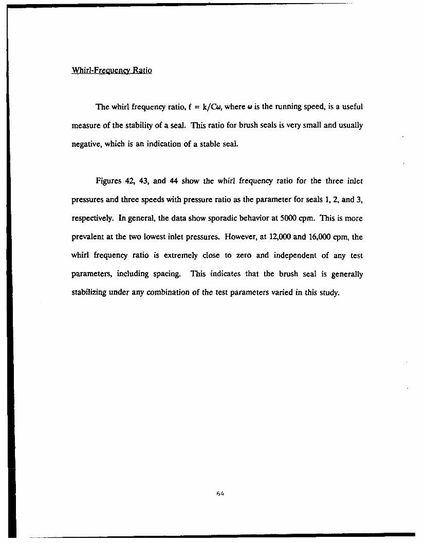
Whirl-Frequency Ratio
The whirl frequency ratio, f = k/Cw, where w is the running speed, is a useful
measure of the stability of a seal. This ratio for brush seals is very small and usually
negative, which is an indication of a stable seal.
Figures 42, 43, and 44 show the whirl frequency ratio for the three inlet
pressures and three speeds with pressure ratio as the parameter for seals 1, 2, and 3,
respectively. In general, the data show sporadic behavior at 5000 cpm. This is more
prevalent at the two lowest inlet pressures. However, at 12,000 and 16,000 cpm, the
whirl frequency ratio is extremely close to zero and independent of any test
parameters, including spacing. This indicates that the brush seal is generally
stabilizing under any combination of the test parameters varied in this study.
64

RPM: 5000 12000 180003.00
PRESSURE RATIOSI = .55 2 = .40
2.00 3 = .40 4 - .35
. 1.00
o~0.00
A. -1.00
-2.00
-3.00 " | I i a a - a .
3.00
2.00
,. 1.00
*10.00- ) 1~
1.00
Cr -2.00
44 -3.00 . .. j .. I • i i - i- i i I -•' i
S3.00
I.I2.00 •-
1.00 -
o.00 -" 3 4 . -
S-t-1.00
-2.00
-3.00
0.0 0.2 0.4 0.0 0.8 0.0 0.2 0.4 0.0 0.2
INLET CIRCUMFERENTIAL VELOCITY RATIO (-)
Figure 42 - Whirl frequency ratio versus inlet circumferential velocity ratio for seal
1.
65

RPM: 5000 12000 160003.00
PPJWRRSV RATIOS1 = .55 2 = .48
2.00 3 ..40 4 = .35
1.000.00
~.-1.00
-2.00
S-3.00 1-'
3.00
2.00
E-4 1.00
S0.00
z "-1.00
-2.00
- 3 . 0 0 -i I ii""=
- 3.00
2.00
1.00
-1.00
-2.00
-3.00 - T
0.0 0.2 0.4 0.8 0.8 0.0 0.2 0.4 0.0 0.2
INLET CIRCUMFERENTIAL VELOCITY RATIO (-)
Figure 43 - Whirl frequency ratio versus inlet circumferential velocity ratio for seal2.
66

RPM: 5000 12000 160003.00
PRESSURE RATIOSI = .55 2 = .48
2.00 3= .40 4 = .35
1.00
0.00 -a. -1.00
-2.00
A -3.00 --- r
3.00
2.00
0 1.00
o.0-.00 -
3 .00w" -2.00 -
-3.00 - I -
- 3.00 - -
2.00
-1.00
-0.00 -di . -4-r-
-3. I I I I - I"0.0 0.2 0.4 0.8 0.8 0.0 0.2 0.4 0.0 0.2
INLET CIRCUMFERENTIAL VELOCITY RATIO (-)
Figure 44 - Whirl frequency ratio versus inlet circumferential velocity ratio for seal3.
I7

Comparison to a Tooth-on-Rotor Labyrinth Seal
It is difficult to define a "comparable" seal to the brush seal due to the nature
of the design of the brush stage; therefore, the shortest tooth-on-rotor seal for which
rotordynamic test data are available was chosen. The labyrinth seal used for
comparison has a rotor diameter of 151.36 mm and a clearance of 0.24 mm. Cavity
width and tooth height are both 3.18 mm. This seal was tested on the same test
apparatus by Pelletti (1990). Data for the rotordynamic coefficients labyrinth seals
are compared to seal 1 using the common pressure ratio of 0.55 at an inlet pressure
of 18.3 bar.
Figure 45 is a comparison of the flow rate for the 4-stage brush seal and the
labyrinth seal described above. The leakage rate for the brush seal is an order of
magnitude lower than the labyrinth seal, which is consistent with all reported leakage
data for brush seals.
As shown in Figure 46, direct stiffness values for the labyrinth seal are
generally negative; whereas, K for the brush seal is always positive. Figure 47 shows
that the cross-coupled stiffness k of the labyrinth seal is always positive, therefore
destabilizing. The magnitude of k for the labyrinth seal increases dramatically as the
inlet swirl increases. Figure 47 also shows that k for the brush seal is low and
generally negative, and does not depend on speed or inlet swirl.
6,9

5 KCPM 12 KCPM 16 KCPM
•@0.20 -
d 0.12 -- RLTYPES
0.0 0.2 0,4 0.6 0.8 1.0 L.2 1.40.0 0.2 0.4 0.60.0 0.2 0.4
INLET CIRCUMFERENTIAL VELOCITY RATIO (-)
Figure 45 - Leakage rate comparison between a 4-stage brush seal and a 9-cavitytooth-on-rotor labyrinth seal.
5 KCPM 12 KCPM 16 KCPM200 -sEAL TYPSs
1 u BRUSH
~100-
z 2Z "0-
-100
0.0 0.2 0.4 0.6 0.8 1.0 1.2 1.40.0 0.2 0.4 0.60.0 0.2 0.4
INLET CIRCUMFERENTIAL VELOCITY RATIO (-)
Figure 46 - Direct stiffness comparison between labyrinth and brush seals.
69

5 KCPM 12 KCPM 16 KCPM
tioo-
z0
0.0 0.2 0.4 0.6 0.8 1.0 1.2 1.40.0 0.2 0.4 0.6 0.0 0.2 0.4
INLET CIRCUMFERENTIAL VELOCITY RATIO (-)
Figure 47 - Cross-coupled stiffness comparison fo; labyrinth and brush seals.
As shown in Figure 48, direct damping values for the labyrinth seal are higher
than the brush seal. For the brush seal, C increases with an increase in rotor speed,
whereas it is relatively constant for the labyrinth seal.
The whirl frequency ratio, f = k/Cw, where a is the running speed, is a useful
measure of the stability of a seal. This ratio for brush seals is very small and usually
negative, which indicates a stable seal, and does not depend on any of the parameters
tested. Figure 49 shows that the whirl frequency ratio for the labyrinth seal becomes
destablizing at high inlet tangential velocities. The ratio for a long labyrinth seal is
approximately 0.5. This ratio for brush seals does not depend on any of the test
parameters, indicating that the seal is very stable at all of the tested conditions.
/0

5 KCPM 12 KCPM 16 KCPM0.5 SUjL Typg-
1 - PRUSH2 ,, LABYRINTH
. 0.4
0O.3
0.2
00.1
0.0 _ I -r -I-T0.0 0.2 0.4 0.6 0.8 1.0 1.2 1.4 0.0 0.2 0.4 0.60.0 0.2 0.4
INLET CIRCUMFERENTIAL VELOCITY RATIO (-)
Figure 48 - Direct damping comparison for labyrinth and brush seals.
5 KCPM 12 KCPM 16 KCPM1.0 SZAL TypCS
I : BRUrSH2 tAUBYRIKIMH
1,00
0.6
S0.20 -
-0.60 --
0.& 0.2 0.4 0.6 08 1.0 1.2 1400o 02• 04 0.60.0 0.2 0.4
INLET CIRCUMFERENTIAL VELOCITY RATIO (-)
Figure 49 - Whirl frcu'f!iency comparison for labyrinth and brush seals.

Torque Imposed on the Shaft Due to Friction
In order to get an accurate measurement for an uncertainty value, four time
traces of the voltage output from each load cell were recorded at set conditions. The
voltage output from each load cell corresponds to a force imposed on the load cell.
This force in turn can be converted to torque. An uncertainty value in this voltage
would ultimately lead to a torque uncertainty.
The four graphs shown in figure 50 correspond to inlet pressure of 7.9 bar,
pressure ratio of 0.14, and rotor speed of 12,000 cpm. Other test conditions were
tested; however, they generated the same type of results. Generally, the voltage has
a resolution of 0.2 volts, which corresponds to a static torque of 74 in-lbs. Intuitively,
this uncertainty is well above any reasonable expected torque imposed by the bristles,
Therefore, measurement of the torque was not possible.

r 0
V12
CNJ
10-
0
0
4-9
4,)
LO C O 0 L O 0 tOLr 0 L O C) 0n0 n )~ 0 U')
30V110A ifldifO 30V110A ifldifo

CHAPTER IV
CONCLUSIONS
Repeatable data for the rotordynamic coefficients and leakage characteristics
of a 4-stage brush seal were obtained. This work was primarily undertaken to
determine the rotordynamic coefficients of the brush seal. The experimental test
results support the following conclusions:
(A) The last stage of the seal group generally develops a slightly higher pressure
drop than the previous stages. The delta P levels across the stages become
approximately equal as the rotor speed and inlet pressure are increased.
(B) At high shaft speeds and high inlet pressures, a fluid film seems to develop
between the bristles and the surface of the rotor. This conclusion is supported by the
"leveling out" of all of the rotordynamic coefficients with increasing running speed and
delta P and the very sporadic behavior of the coefficients at the lowest rotor speed
and lowest inlet pressure.
(C) The leakage flow rate increased with the order of testing; i.e., seal 3 leaked more
than seal 1, which leaked more than seal 2. This suggests that even with a line-to-line
fit, i.e., no interference between the bristles and rotor, wear does have an effect on
the mass flow rate.

(D) Increasing the inlet tangential velocity causes a slight increase in leakage. This
trend is most prevalent on the second and last seal tested, suggesting that this
behavior occurs due to worn-in conditions.
(E) As the rotor speed and inlet pressure increase, leakage becomes more dependent
on the pressure ratio, again suggesting the formation of the fluid shear layer.
(F) The -otordynamic coefficients, K, k, C, and c, do not depend on seal spacing or
inlet tangential velocity.
(G) The direct stiffness coefficient is frequency dependent and always positive. The
mean value of K is positive, yet not large in magnitude, for all conditions tested. K
increased slightly with an increase in pressure ratio, and did not depend on the otiher
test parameters.
(H) The cross-coupled stiffness coefficient is very low and generally negative,
therefore stabilizing. k is generally independent of all test parameters, particularly
the inlet pre-swirl.
(I) The direct damping coefficient increases with an increase in the rotor speed and
inlet pressure. The intercept of the lm(tx/9) versus frequency at w = 0 is not zero.
This could be attributed to coulomb friction caused by the bristles on the shaft.

(J) The whirl frequency ratio indicates that the brush seal is extremely stable. This
ratio did not vary with any of the test parameters.
The reader should bear in mind that rotordynamic coefficient results are
compared for an 8-cavity labyrinth seal and a 4-stage brush seal. A 4-stage brush seal
was tested in order to create large enough forces to measure. The 8-cavity labyrinth
was the shortest seal for which rotordynamic coefficient data were available. Data
for those seals indicate that replacement of a standard labyrinth seal with a multi-
stage brush seal will generally improve the rotordynamic characteristics if the
labyrinth seal is destabilizing,the rotor due to fluid preswirl. This conclusion follows
from the low or negative cross-coupled stiffness value for brush seals, independent of
fluid preswirl. However, given that brush seals have lower damping values than
labyrinth seals direct replacement might, in some cases, cause a slight degradation of
rotor response. a careful rotordynamics analysis to consider the influence of replacing
a labyrinth seal by a brush seal is advised.
i ! I

REFERENCES
Bolleter, U., Wyss, A., Welte, I. and Sturchler, R., "Measurement of HydrodynamicInteraction Matrices of Boiler Feed Pump Impellers", ASME Journal of Vibrations.Stress and Reliability in Design, Vol.109, 1987, pp. 144-151.
Braun, M.J., Hendricks, R.C., and Canacci, V., "Flow Visualization in a SimulatedBrush Seal", ASME Paper No. 90-GT-217, ASME Gas Turbine Conference, Brussels,Belgium, June 1990.
Childs, D.W., Baskharone, E., and Ramsey, C., 'Test Results for RotordynamicCoefficients of the SSME HPOTP Turbine Interstage Seal with Two Swirl Brakes",Accepted for presentation at the ASME-ASLE Tribology Conference, 7-10 October1990.
Childs, D.W., and Ramsey, C., "seal Rotordynamic Coefficient Test Results for aModel SSME ATD-HPFTP Turbine Interstage Seal With and Without a Swirl Brake",Accepted for presentation at the ASME ASLE Tribology Conference, 7-10 October1990.
Childs, D. W., and Scharrer, J.K., "Experimental Rotordynamic Coefficient Resultsfor Teeth-on-Rotor and Teeth-on-Stator Gas Seals", ASME Transactions. Journal ofengineering for Gas Turbine and Power, Vol. 108, October 1986.
Chupp, R.E., and Nelson, P., "Evaluation of Brush Seals for Limited-life Engines",AIAA Paper No. 90-2140, AIAA Conference, Orlando, Florida, July 1990.
Coleman, H.W., and Steele, G.W., Experimentation and Uncertainty Analysis forEngineers, Wiley-Interscience Publication, 1989, pp. 173-174.
Ewins, D.J., Modal Testing: Theory and Practice, Research Studies Press Ltd.,Letchworth, Hertfordshire, England, 1986.
Ferguson, J.G., "Brushes as High Performance Gas Turbine Seals", ASME Paper No.88-GT-182, ASME Gas Turbine Conference, Amsterdam, The Netherlands Tujne1988.
Flower, R., "Brush Seal Development System", AIAA Paper No. 90-2143, AIAAConference, Orlando, Florida. July 1990.
Holle, G.F., and Krishnan, M.R., "Gas Turbine Engine Brush Seal Applications",A'AA Paper No. 90-2142, AIAA Conference, Orlando, Florida, July 1990.

Holman, J.P., Experimental Methods of Engineers, McGraw-Hill, 1978, p. 45.
Pelletti, J.M., "A Comparison of Experimental Results and Theoretical Predictions forthe Rotordynamic Coefficients of Short (L/D = 1/6) Labyrinth Seals", Master'sThesis, Texas A&M University, College Station, Texas, 1990.
Scharrer, J.K., "A Comparison of Experimental and Theoretical Results for LabyrinthGas Seals", Doctoral Dissertation, Texas A&M University, College Station, Texas,1987.
Schenck, H., Theories of Engineering Experimentation, 3rd Ed., McGraw-Hill, NewYork, 1979.
White, R.G., and Pennington, R.J., "Practical Application of the Rapid FrequencySweep Technique for Structural Frequency Response Measurement", AeronauticalJgoural, Paper No. 961, May 1982, pp. 179-200.

APPENDIX A
IMPEDANCE FUNCTION PLOTS
The following 36 figures are the impedance plots which graphically show the
data from which the rotordynamic coefficients are determined.
7I 9

RPM: 5000 12000 16000
4"0 PRUREVATIOS1 m .65 2 .40
400 " 3 - .25 4 ,..14
350-
3 0 0--
S-o
40o-ISO
300-600
0 ' : | 1 1 I"] I I I I I'1 I I I - 1 I i ni ri I fi ll[ '| I | I I I I • '
NN -
r34 4
100
1500
400-
360
0P - -F r I7 T T - -TTF IIIIT T M I I I I I I I I
5 00
-4, 60 -
200060
*~100-
010 2030 4050 60 70 0 0 1020 30 4050 607080 0 10 2030 40 506070 0
Frequency (Hz)
Figure 51 - Direct stiffness impedance graph for seal 1 with no fluid pre-rotation.
1i01

RPM: 5000 12000 16000
4.50- PRSSMR RATIOS1 = .65 2 -. 40
400 3 s5 4 - .14
A 300
too -100-0
500
450
400
300-
S• -As
o. 200
-04
so--
i ,, i W ~ 'i j i i i I ,I I I l l t l l ll i iTiltlltitllli l
1) 1050-
3800
AI
lo 210 • ~ o • o .o o o, • o
2500
ZO0 -Fr'equency (Htz)
Figure 52 - Direct stiffness impedance graph for seal 1 witb intermediate fluid pre-
rotation.
C 1
-- -Fi I I I I I r II I I I- I I11 1 1 1 j l 1 1 1 1 1 j l

RPM: 5000 12000 16000
500-45•0- FPJM.9UM RATIOS
4 1 .65 2 .40
400 .325 4 .14
360-
.0 300-
boo -200 -1
150-
100-
50-
0- 1 1 1 1 1 1 1 IT T I I- I II f I I I rT-T-rTT7- 1 Ill I III ill
4600
360-Z 300
X ~260-14 200-
. 160--ý -.
v ~100-C4 50-
0 1 I ]11 111 1 I II - ItT 1 I1 I T1 I I I I I I I I I I I TITI-ITII 1
500 "
460-
400
350-
S 300 -6-1
200-
100-
50-
0- 1 I'I' I 'I I I I I I
Frequency (Hz)
Figure 53 - Direct stiffness impedance graph for seal 1 with high fluid pre-rotation.

RPM: 5000 12000 18000
-PRESURE RATIlOSI = .55 2 = .40
100- 3 .25 4 .14
s o --
-10-.• i I I I I1 I'l I "" I I I I i I. I I I I 'f 1 1 1 1 I I I I | | I ] I I | I I | I~ r I |
_100-
N-Do
ra -- -
150
100-
* O0 -- -50-
-100-
0 10 90S•0 40 0 so 70 o a • to 3040o 5 60 o70 010 • 0 400 so o 70 5
Frequency-(Hz)
Figure 54 - Cross-coupled stiffness impedance graph for seal 1 with no fluid pre-rotation.

RPM: 5000 12000 16000150
- PJS RATIOS1 = .55 2 = .40
100- 3 - .26 4 = .14
500
z 0 -
"AIN
60-0-0
-100-
160
100-
50-
- I1 0 0
* ;j I I I 'IiI I I I JI [ I t I 1 ' I I'I I I I2 I I I I I'I I I I I I III I
0 _50--
_1-50--
0 1020I30 40 50 60 7080 01029023040 5060 7060 010 2030 4050 60 7080
Frequency (Hz)
Figure 55 - Cross-coupled stiffness impedance graph for seal 1 with intermediate fluid
pre-rotation.

RPM: 5000 12000 16000
- PRESSURE RATIOSI = .55 2 = .40
100- 3 w .25 4 - .14
50-zz 00- -
Aw 06 _ _
-100
- 150 I - '" 1 I | 1 1 1 1 1I } "FI ] | I l I I i I I I -tI
150-
j 100-
N. . 50o-
%% --
lSO _50
- 1 5 0 - I I T - I I 'I I I 'I f I I i I I I I I I I i I I ) l TI I I I I l 'lT T T F Ti i I I I i I-100•
150
100
04-
-100 •
-
F 0 10 20 30 40 50 070 0 10 20 30 40 0•0•70go 0o •o •30040506070 So
Frequency (Hz)
Figure 56 - Cross-coupled stiffness impedance graph for seal I with high fluid pre-rotation.
Sa I II I P I I5

RPM: 6000 12000 16000
-PYSSMUR RTIOSI - .65 2 = .40
10- 3 .25 4 - A4
100-
-so-
S10
-001
-100-
-I0 1 | 11 |I 1 i 11 - ilI|II1 1 l li11 I i IiI I - li i i l il li I
-100 TT T-
100
350-
100-
1.*0
G o-00
-so-
0 10 2030 405060 70 0 0 10 20 30 40 0so070S00o1010o0o40 6060 -to0
Frequency (Hz)
Figure 57 - Direct damping impedance graph for seal I with no fluid pre-rotation.
86(

RPM: 5000 12000 16000
?U3ESVR R&TIOS1 6 ,51 2 ,40
10 3 .25 4 14
100-
50-
-50
z
-50-
100-
6 0 --
Frequency (Hz)
Figure 58 - Direct damping impedance graph for sea] I with intermediate fluid pre-rotation.
'07
' AI II iI

RPM: 5000 12000 16000t00
- PSSURZ RTIos.35 2 .40
160- 3 ..25 4 .14
o-
-60-
-100- I I I I I III I I I I I't I tIi 1 I I '" 1 I' I' I 1 I II
200-
100-
14loo
60
60
-80too
Frequency (Hz)
Figure 59 - Direct damping impedance graph for seal 1 with high £tid pre-rotation.
.0I

RPM: 5000 12000 16000500-
450O F RESSV-U P4,11OS-- 1 2 =.40
"103 3 25 4 14
-300
250
60-
,,-- T77-77-M_
600-
400
400
N., 360-
H - 300 7
•too - -
100-
s0
0o- 1 T 7 -1 -T-T - -r T -
500
460-
400
Sa
250-
0-40: 160
100-
0 10 20 30 40, 50 0 "70 So 0 01090 30 40 60 "70 60 0 10 0 230 " 50 60 70 80
Frequency (Hz)
Figure 60 - Direct stiffness impedance graph for seal 2 with no fluid pre-rotation.
•9(

RPM: 5000 12000 1600C
46 PR.SSURM RATIOS1 - .55 2 = ,40
400 3 .26 4 - .14
o0 -
A~ 300
r. 250
ZOO
156
100-
0 - I I I I I I I ] il I I I I I I I I I I I I I I I I I I I I I I I I I I I
S00
350-
300-260
S 1-200-
* 150-
100-04
Go-50
"460-400-
350-
300 -1
S 250-
200-
010 2030 4050 60 TOS0 0 10 2030 40U S0 070 0 0 10 20 3040 50 0TOSO
Frequency (Hz)
Figure 61 - Direct stiffness impedance graph for seal 2 with intermediate fluid pre-rotation.
90C

RPM: 5000 12000 16000
I = .55 2 = 40
400 3 * 4 -. 14
350
"200-
2500
t oo -0.0
Soo 4
800-
460
400
350-
zD -Sz~~OO---
lsoo hIV ~100 7
480
3160-4 50-
4w
300--
200j
"0- 10 10 2030 4050 607T 060 10 203040 50 6070 80 0 10 20 304050 6070680
Frequency (Hz)
Figure 62 - Direct stiffness impedance graph for seal 2 with high fluid pre-rotation.
9!

RPM: 5000 12000 160001I00
- PRESSURE RATIOSI = .55 2 = .40
100- 3 = .25 4 - .14
150•
o
0o
N1 -100i-1 0- -____________
-100
-l ) " i l 'I I I'1 1 I I I1 I I I I I I If I- I I I I I I I l'l 1 I I I I I I 1 1 1 1 1 1- 1 1 1I
150--
100
60
-m 0
.43
do -Joe
60-
-100-160- • 1 - T-11TFrFrT Ii 111
0 10 0O30 40 50 0 70 S0 0 1020 30 40 60 070 b0o010 0 304050 60 70to
Frequency (Hz)
Figure 63 - Cross-coupled stiffness impedance graph for seal 2 with no fluid pre-
rotation.
(0;,

RPM: 5000 12000 160001501
1 .55 2 .40100 - 3 =:.25 4 :.14
"1- 0a.
-100
S100
-l1O -- r-TT-]F TA r, ' "I I lI l II llr- II i TI II
-100-
50-
0- 3
- -50 1ZZZI IIITT7r=I T77
_ - -F
"-150 ' IIJI11 •]l1 l1 I II) IIllrl~ 1111J1
0 10 20 30 44D 50 60 70o 0 0 20 30s 40 50 So 70 o so 1 o So 40 50 60 70 5o
Frequency (Hz)
Figure 64 - Cross-coupled stiffness impedance graph for seal 2 with intermediate fluidpre-rotation.
1591
- I
*. . _,Il | |

R.P: 5000 12000 160001540
- PRESSUR& IAT1o1I = .5S 2 = .40
100 .25 4 J4
50-
00
100
10o-
z
x 00
.0
0:pl
-4
-100
150-
-100 -
-100d
0 10 20 30 40 50 60 70 8001 0 30 40 50 60 70 50 0 10 LO 30 40 50 60 70 50
Frequency (Hz)
Fligure 65 - Cross-coupled stiffness impedance graph for seal 2 with high fluid pre-rotation.

RPM: 5000 12000 16000
PISSURI RAIPATIOS1I .5,5 2 = .40
1560 3.- :25 4 - .14
: so -
0 0
500-z
ooo
0 o-
150-
100
-soo •l~ l lT~ llli I T..1.- T i ,,l lvi I li ii II I i I I i z i , I ---T -II200
10-
Frequency (Hz)
Figure 66-Direct damping impedance graph for seal 2 with no fluid pre-rotation.
U'I

P.PM. 5000 12000 16000200-
- PRRSS1JME RLTVMSI .65 2 = .40
I0W 3 " .2• 4 = .14
100-
zoo
U 1§00
-60--
-100-i I 02 02 0458 08
100-tee • iliTT'lliT lll-T Illl if I ,l I li l -T -111 l f Ml•0 10 0 30o40 50•ro, o0 70. 800 020304 5o0, 60 ., 70a 0to 40 5 So.,o 7 So,,
Frequency (Hz)
Figure 67 - Direct dampirg impedance graph for seal 2 with intermediate fluid pre-rotation.
9 ("

RPM: 5000 12000 10000too
- Pla TmROSI - .66 2 - .401 6 0 - - 3 Z 5: t • 4 - . 4"
-60
-100 1 I 1 i i | it] [ I I [ 1 I I/ I ||l I I 1M I fI I l I ~ ' I 14 I I I I 1'•i iIj
z*
160-
to0-
164
-Go-
0 10 20 30 40 50 0 70 80 0 10 20 30 60 60 0 0 0 10 30 40 5000TO W0
Frequency (Hz)
Figure 68 - Direct damping impedance graph for seal 2 with high fluid pre-rotation.

RPM: 5000 12000 16000800-
450 PRSSVE RATIOS1 = .55 2 = .40
4.00 3.24 A4
350
w
1 00-
0 60
05 - -T T-- T-_TII-r T500-
B.
4600
400
350-
300
- ip
1 00-
60
600-i
- • B . 4 w
060400-
60-
300-
3800
60
0 10 20 SO40 50 " TOS0 0 10 2030 40 50 " 70 0 0 10 2030 40 50 6070 0
Frequency (Hz)
Fligure 69 - Direct stiffness impedance graph for seal 3 with no fluid pre-rotation.

RPMd: 5000 12000 16000500-
450-• PRISSUS RLTIOS
360
_ w .86 2 - .40
3800
2500
a o.
150-
100-
50
0-
4000
6 300
Do IN ow+•~oo AP -o 'oJ oe o+ o, os oe o o
- S600
400
460
* 50
0O~ _______P_1____1_1_1__nII_____I 'hi 'hl Jill Jil
0 10 2030 4050 60 TO0 0 10 2030 40 50 00 T0 0 10 9030 40 060 TO 00
Frequency (Hz)
Figure 70 - Direct stiffiess iwpedance graph for seal 3 with intermediate fluid pre-
rotation.
t)0

RPM: 5000 12000 16000500
450- PRESSURE RATIOSI = .55 2 = .40
400 3 = .25 4 = 14
350
*A 300
,oo Z50
100
150
60 _0 I [ T I T T ] T I I I |T I r I i 3 T7 j m r I l +'-=7 - 1 ~ r IT 7i I I I I -
480-
400
300
45°280
Z -60 -•
200-
* 150 -
W too 100
060-
480-
400-
360 __4
A~ 800 -
* 250-
200-
1600
80-
0 10 20 30 40 50 80 ?700 0 0 20,30 40 50 o 706 0 0 10 20 30 40 50 o 0 70 So
Frequency (Hz)
Figure 71 - Direct stiffness impedance graph for seal 3 with high fluid pre-rotation.
I1M)

RPM: 5000 12000 18000150 -
PRESSURE RATiOS1 = .55 2 = .40
0O0 3 = .25 4 = .14
so-r 0- -A50
0 -50 -
50--100-
60- 2
-E -50-- a
0-,o -_
0. 0-
o100
160-
S 50-0
0.0
--IIO ---
0 10 20 30 40 50 60 TO780 0 10 20 30 40 5060 70 60 0 10 20 30 40 50 60 70 80
Frequency (Hz)
Figure 72 - Cross-coupled stiffness impedance graph for seal 3 with no fluid pre-
rotation.
1Ot

RPM: 5000 12000 16000ISO-
- PRESSURE RATIOSI = .55 2 ..40
100 3 = .25 4 = t4
S50--
ISO-
o. o
-100-150
S.-.. -50-
-:00
- 50 I I I I I I-M r- '-T-M i T T T- I I I I I I I F I I i i I I I"1 "ii I I I I' i M
150-
100-
.0
-100 -
-tI o I l l ,1 • ll1 I l ll i ' 1 1 1 1 T T - I I I I I I Il irT 7 T -MI
0 10 20 30 40 50 60 TO ao 0 10 20 30 40 50 60 70 60 0 o0 20 30 40 50 60 70 So
Frequency (Hz)
Figure 73 - Cross-coupled stiffness impedance graph for seal 3 with intermediate fluidpre-rotation.
102

RPM: 5000 12000 16000
- PRESSURE RATIOS1 - .55 2 = .40
100- 3 .25 4 .14
so-
_150--UTt
0 .. - 6 0 - -
160-
60
'-60- 4
160--
100-
,a
-0--
44
_100.
-150 IIIF i t-IIIl~ 11 11 111 1- Jo lj! Il 'I l1l11 (l ' ' Iii I -~ " r 'lf IlIlj ii If+
o 10 20•3•o 40 560? TOo 80 o10 20 30 40 50 0 70 60 •10o 2o 0 4o 50 50 7o DO
Frequency (Hz)
Figure 74 - Cross-coupled stiffness impedance graph for seal 3 with high fluid pre-
rotation.
103

RPM: 5000 12000 16000200-
- PRESSURE RATIOS1 = .55 2 .40
160- 3= .2 4 .14
" d' 100
0--
0. 0
-100
200-z
1500
A.
1 -
1. 0 A02 04 08 08 O• 04 0a 08 0• O4 06 08
asa
500
150-
0100-
50
-50-
0 10 203040 50 607080 010 2030 4050 6070 80 010 2030 4050 6070 80
Frequency (Hz)
Figure 75 - Direct damping impedance graph for seal 3 with no fluid pre-rotation.
104

RPM: 5000 12000 16000ZO00
- PRSM PTItOS1 - .65 2 - .40
160- 3 .25 4 a .14
5 100I
A
100
loc
_-
a-o
000180-
ra. 100•
300
1.
AA
-0
0 10 20 30 40 50 60 70 00 0 10 20 30 40 50 60 70 80 0 LO 20 30 40 50 80 70 80
Frequency (Hz)
Figure 76 - Direct damping impedance graph for sea] 3 with intermediate fluid pre-rotation.
105
S.. .. . .- 100-. i l I 'I I 1 11 1

RPM: 5000 12000 16000zoo-
- PRESSURE RATIOS1 = .55 2 = .40
150- 3 =.25 4 =.14
', 100•
C*
-50
--200
zX, 160--
100-
05
" 0-
-60 00
- 100 I I I I I I I I I I I I I I I i t I I I I I I I I I I'1 1 I I I I '1' 1 I 1 1 I ! I I I 1 1I
200
160-
S 100-
50-
-50
-100- 'iiII1111II111 111 I11111I''
0 10 1 0 30 40 50 60 70 60 • 10 20 30 40 50 60 70 60 0 O0 30 40 50 60 70 60
Frequency (Hz)
Figure 77 - Direct damping impedance graph for seal 3 with high fluid pre-rotation.
106

APPENDIX B
TABULATION OF TEST CONDITIONS AND TEST RESULTS
The following 9 tables list the test conditions and test results for each seal
configuration. Test results include the mass flow rate, volumetric flow rate, and
temperatures before and after the test seal. For seals 2 and 3, cavity pressures
between seal stages are listed.
107

Table BI - Static and dynamic test data for seal I cases with no fluid pre-rotation.
CAM CPM P. PI/P. T. Tb U. in q
(bar) (-) (K) (K) (m/s) (kg/*) (Us)
I 5030 7.9575 0.533 299 299 0.00 0.0067 0.71462 5030 7.U877 0.387 299 300 0.00 0.0070 0.74733 5030 7.9432 0.238 300 300 0.00 0.0071 0.76234 5030 7.9416 0.135 300 300 0.00 0.0071 0.7639
5 5030 13.1526 0.539 301 303 0.00 0.0096 0.62436 5030 13.1395 0.391 302 305 0.00 0.0103 0.67657 5030 13.0518 0.245 303 304 0.00 0.0110 0.72053 5030 13.0931 0.134 303 303 0.00 0.0114 0.7415
9 5030 18.2597 0.544 305 305 0.00 0.0136 0.638110 5030 18.2499 0.396 305 305 0.00 0.0155 0.729711 5030 13.2392 0.249 305 305 0.00 0.0173 0.811112 5030 18.2222 0.143 305 303 0.00 0.0152 0.8498
13 12000 7.9091 0.553 305 308 0.00 0.0061 0.658014 12000 7.1679 0.400 305 310 0.00 0.0064 0.693715 12000 7.3706 0.244 305 311 0.00 0.0066 0.715316 12000 7.-732 0.138 305 313 0.00 0.0067 0.7299
17 12000 13.0115 0.535 305 309 0.00 0.0094 0.61631i 12000 13.1293 0.393 306 311 0.00 0.0102 0.666119 12000 13.0331 0.249 306 311 0.00 0.0108 0.708020 12000 13.1302 0.139 306 314 0.00 0.0116 0.7614
21 12000 18.2146 0.543 307 310 0.00 0.0136 0.641722 12000 13.2068 0.403 307 312 0.00 0.0155 0.729723 12000 18.3110 0.241 308 312 0.00 0.0190 0.890324 12000 18.1830 0.147 308 313 0.00 0.0221 1.0426
25 16000 7.9111 0.535 308 316 0.00 0.0058 0.631026 16000 7.3757 0.395 308 315 0.00 0.0062 0.677527 16000 7.9698 0.241 308 322 0.00 0.0063 0.680025 16000 7.1910 0.133 308 326 0.00 0.0063 0.6586
29 16000 13.0672 0.542 309 317 0.00 0.0089 0.558630 16000 13.0791 0.399 309 319 0.00 0.0097 0.643031 16000 13.0737 0.241 309 323 0.00 0.0105 0.710332 16000 13.0991 0.133 309 326 0.00 0.0120 0.7899
33 16000 18.2200 0.544 310 317 0.00 0.0136 0.644134 16000 18.2335 0.401 310 318 0.00 0.0160 0.757435 16000 13.2961 0.254 310 321 0.00 0.0199 0.932036 16000 18.1350 0.144 310 321 0.00 0.0244 1.1524
MIS

Table B2 - Static and dynamic test data for seal I cases with intermediate fluid pre-rotation.
Caw CPM P. PdP. T. Tb U. Ch q(bar) 0 #X) (K) (ms) ftkg/) (119)
37 3030 7.9317 0.561 307 305 8,71 0.0075 0.811235 3030 7.9647 0.414 307 303 9.27 0C001 0.563739 5030 7.9390 0.262 307 305 9.50 0.0032 0.835540 5030 7.9S94 0.140 307 306 9.7: 0.0084 0.9048
41 5030 13.1203 0.536 307 304 3.11 0.0116 0.756042 5030 13.0967 0.400 307 306 8.72 0.0124 0.812943 5030 13.0806 0.252 307 305 9.73 0.0139 0.906544 5030 13.0561 0.143 307 305 10.83 0.0155 1.0096
43 5030 18.2253 0.557 308 305 8.63 0.0173 0.508646 5030 18.2242 0.397 308 306 10.29 0.0205 0.959047 5030 18.2300 0.259 308 305 12.36 0.0248 1,151848 5030 18.1928 0.156 308 305 12.74 0.0257 1.1870
49 12000 7.9181 0.565 307 309 8.85 0.0077 0.824950 12000 7.88357 0.410 307 310 9.32 0,0080 0.868351 12000 7.9087 0.250 307 314 9.47 0.0082 0.882552 12000 7.5935 0.143 307 315 9.74 0.0034 0.9070
53 12000 13.1035 0.545 307 310 3.23 0.0113 0.771554 12000 13.0349 0.410 307 311 9.06 0.0130 0.344655 12000 13.1185 0.254 307 312 9.92 0.0142 0.924456 12000 13.0354 0.141 307 313 11.10 0.0160 1.0346
57 12000 18.2242 0.358 307 310 8.74 0.0174 0.814158 12000 18.2595 0.401 307 311 10.28 0.0206 0.953259 12000 18.1827 0.243 308 311 12.53 0.0231 1.167260 12000 18.1760 0.157 308 312 12.74 0-0257 1.1871
61 16000 7.9580 0-539 307 316 8.60 0.0074 0.R01462 16000 7.8886 0.402 307 317 9.37 0.0080 0.873363 16000 7.8184 0.251 307 319 9.60 C.0083 0.894764 16000 7.9526 0.143 307 323 9.65 0.0084 0.8990
65 16000 13.0441 0.343 308 31o 8.18 0.0113 0,762566 16000 13.0925 0-394 308 317 8.74 0.0125 0.814567 16000 13.0251 0.260 308 320 9.34 0.0134 0.,70568 16(00 13.1103 0.145 308 322 10.34 0.0148 0,9632
69 16000 18.2938 0.343 308 315 8.38 0.0168 0.781170 16000 18.2723 0.400 308 317 9.74 0.0196 0.907471 16000 18.1722 0.233 308 318 11.34 0.0233 1.103472 16000 18.2124 0.150 308 3-8 12.73 0.0253 1.1867
1 09

Table B3 - Static and dynawc test data for seal I caes with high fluid pre-rotation.
Cue CIM P. PV1. T. Tb U. in q(bar) (-) M) () (nI/) (ktIa) 0/2)
73 5030 7,9375 0,549 295 295 18.63 0.0085 0.867774 5030 7.9132 0.407 295 296 19.62 0.0090 0.913975 5030 7,9486 0.252 295 296 20.33 0.0094 0.949376 5030 7.9259 0.147 295 295 20.80 0.0096 0.9684
77 5030 13.1273 0.548 296 295 17.31 0.0130 0.806478 5030 13.1593 0.400 296 295 18.47 0.0139 0.859)
79 5030 13.0713 0.248 296 295 19.42 0.0146 0.904280 5030 13.1609 0.143 296 295 2045 0.0155 0.9524
81 5030 18.2925 0.553 297 296 17.10 0.0179 0.796482 5030 18.2426 0.403 297 296 19.25 0.0201 0.896383 53 18.3513 0.242 298 296 22.98 0.0244 1.069984 5030 18.2979 0.150 298 296 25.36 0.0270 1.1807
85 12000 7.8612 0.564 300 305 21.05 0,0094 0.980386 12000 7.8463 0.404 300 305 22.54 0.0102 1.049687 12000 7.9533 0.268 301 307 22.88 0,0103 1.065288 12000 7.8911 0.151 301 308 23.08 0,0105 1.0746
89 12000 13.0524 0.549 301 305 20.77 0.0154 0.967090 12000 13.1159 0.409 300 305 22.04 0.0165 1.026091 12000 13.0716 0.256 300 305 23.37 0.0174 1.088792 12000 13.0810 0.141 300 305 25.38 0.0193 1.1820
93 1200M 18.2460 0.545 300 305 21.25 0.0221 0.989394 12000 18.2145 0.389 300 305 24.06 0.0253 1.120395 12000 18.2359 0.247 300 304 25.39 0.0271 1.182496 12000 18.2448 0.142 300 304 25.36 0.0269 1.108
97 16000 7.9138 0.563 301 312 17.60 n'.0078 0.819298 16000 7.8899 0.388 30) 314 19.45 0.0087 0.905799 16000 7,9503 0.247 302 316 19.90 0.0089 0.9265100 16000 7.9397 0.147 302 318 20.18 0.0090 0.9399
131 I•O0 13.0767 0.547 303 312 17.90 0.0131 0.83354tv2 16000 13.0756 0.402 303 315 19.41 0.0143 0,9041103 16000 13.1210 0.245 303 316 20.45 0.0151 0.9526104 16000 13.0796 0.138 304 317 21,67 0.0160 1.0091
105 16000 18.1726 0.553 305 312 18.34 0.0192 0.8775106 16000 18.2538 0.399 305 315 20.93 0.0215 0.9749107 1600M 18.2757 0.250 305 315 24.01 0.0248 1.1184108 16000 18.2159 0,146 306 314 25.45 0.0265 1.1851
, a I I I I I I I I I I 0

Table 84 - Static and dynamic test data for seal 2 cases with no fluid pre-rotation.
Caw CPM P. PJP. T. T. U. d, q P.1 P.4 P.. P(bar) (-) (K) (IK) (Ws.) (kIle.) (0/5) (bar) (br) (bar) (bir)
1 5030 8.0127 0.523 297 296 n.00 0.0057 0.5853 7,7009 7.3903 6.1087 4.1904
2 5030 7.3829 0.407 297 296 0.00 0.0059 0.6221 7.5164 7.1693 5.4147 3.2116
3 5030 7.9104 0.248 297 296 0.00 0.0063 0.6596 7.5837 7.0236 4.7533 1.9607
4 5030 7.8958 0.137 297 297 0.00 0.0066 0.6298 7.3814 6.7079 4.1233 1.0820
5 5030 13.0247 0.555 297 296 0.00 0.0083 0.5284 12.1172 10.9088 9.0561 7.2331
6 5030 13.1021 0.402 297 296 0.00 0.0090 0.5703 11.8656 10.2875 7.7399 5.2673
7 5030 13.1293 0.251 297 297 0.00 0.0097 0.6129 1t.6967 9.7119 6.4065 3.30178 5030 13.0934 0.135 297 297 0.00 0.0105 0.6669 11.6927 9.6832 5.7529 1.7615
9 030 18.2435 0.553 293 297 0.00 0.0115 0.5252 16.7636 14.9818 12.3825 10.084310 5030 13.1902 0.400 298 297 0.00 0.0126 0.5762 16.1586 13.7116 10.1862 7.2723
11 5030 18.2053 0.248 298 297 0.00 0.0139 0.6337 15.3093 12.2073 7.9877 4.5181
12 5030 18.2542 0.136 298 297 0.00 0.0156 0.7094 14,6648 11.1653 6.3807 2.4868
13 12000 7.7945 0.570 299 304 0.00 0.0048 0.5112 7.2449 6.4561 5.5700 4.4468
14 12000 7.3396 0.401 299 304 0.00 0.0055 0.5797 7.0624 5.9851 4.7488 3.1431
15 12000 7.3396 0.244 299 306 0.00 0.0057 0.6134 6.9013 5.6061 3.9999 1.916116 12000 7.9101 0.136 299 310 0.00 0.0060 0.6459 6.6124 5.2275 3.4592 1.0749
17 12000 13.1264 0.546 300 304 0.00 0.0086 0.5502 11.3320 9.6829 8.5910 7.1701
18 12000 13.0203 0.403 300 305 0.00 0.0092 0.5912 11.0828 9.0440 7.1536 5.2525
19 12000 13.1307 0.234 300 307 0.00 0.0102 0.6512 10.7461 8.5151 5.8151 3.077020 12000 13.0627 0.130 300 310 0.00 0.0108 0.6938 10.8088 8.3786 4.9422 1.7044
21 12000 13.2292 0.557 301 304 0.00 0.0116 0.5318 15.8460 13.5164 11.9341 10.1454
22 12000 18.2040 0.397 301 304 0.00 0.0127 0.5852 15.3207 12.4079 9.5394 7.233723 12000 18.2049 0.245 301 305 0.00 0.0144 0.6617 14.6686 11.2530 7.0912 -4.466424 12000 18.2100 0.133 30t 309 0.00 0.0168 0.7703 13.9074 10.2264 53371 2.4221
25 16000 7.8304 0.553 302 313 0.00 0.0045 0.4971 6.5464 5.6965 5.0696 4-371126 16000 7.9072 0.409 302 312 0.00 0.0052 0.5564 6.1685 4.9855 4.0994 3.2339
27 16000 7.8631 0.247 302 314 0.00 0.0053 0.5624 6.1632 4.6993 3.4679 1.9398
28 16000 7.8642 0.135 303 322 0.00 0.0053 0.5628 6.2232 4.6473 3.0978 1.0613
29 16000 13.1284 0.542 304 311 0.00 0.0070 0.4542 11.3931 9.5321 8.0948 7.1162
30 16000 13.0898 0.404 304 315 0.00 0.0074 0.4821 11.1100 8.8555 6.6115 5.2851
31 16000 13.1055 0.242 304 319 0.00 0.0079 0.5140 10.7252 8-1794 5.2316 3.1710
32 16000 13.1264 0.127 303 325 0,00 0.0083 0.5315 10.5871 7.8365 4.3169 1.6712
33 16000 13.2571 0.550 305 311 0.00 0.0095 0.4397 15.9942 13.4060 11.2929 10.0486
34 16000 18.2555 0-398 305 317 0.00 0.0120 0.5572 15.0706 12.2000 8.8868 7.268535 16000 18.2069 0.244 305 315 0,00 0.0122 0.5652 15.0115 1A.4591 7.1681 4.4461
36 16000 18.1924 0.141 305 323 0.00 0.0138 0.6422 14.2010 10.4914 5.6802 2.5680

Table B5 - Static and dynamic test data for seal 2 cases with intermediate fluid pre-rotation.
Cane CPM P. Pb/P. T. Tb U. di q P-, P.., P_. Pb(bar) (-) (0) (K) (t/a) (kg/a) (I/V) (bar) (bar) (bar) (bar)
37 5030 7.8370 0.550 303 301 7.29 0.0063 0.6792 6.7128 5.9240 5.3351 4,321438 5030 8.0560 0.417 305 304 7.65 0.0066 0.7130 6.3782 5.2684 4.1215 3.361039 5030 7.9150 0.240 303 302 8,23 0.0072 0.7672 6.2131 4.7870 3.6272 1.9023
40 3030 7.9772 0.137 303 302 8.33 0.0073 0.7762 6.1792 4.6230 3.2916 1.0909
41 5030 13.0738 0.537 304 302 6.72 0.0096 0.6258 11.1"02 9.4306 5.0765 7.020942 5030 13.0292 0-397 304 302 7.06 0.0102 0.6576 10.7859 8.6070 6.7262 5.167543 5030 13.1400 0.243 304 302 7.43 0.0107 0.6919 10.5266 7.9922 5.4567 3.186644 5030 13.0734 0.140 304 303 7.70 0.0111 0.7173 10.3500 7.6288 4.7783 1.8269
45 5030 18.2404 0.545 305 305 6.51 0.0130 0.6067 15.4797 13.2641 11.4087 9.944646 5030 18.2138 0.400 305 305 7.11 0.0142 0.6620 14.9439 12.2252 9.4199 7.283547 5030 18.2062 0.243 305 304 7.58 0.0151 0.7062 14.4422 11.2041 7.2337 4.415348 5030 13.1766 0.137 306 304 8.15 0.0162 0.7594 13.9349 10.3444 5.6315 2.4892
49 12000 7.9748 0.550 305 308 6.29 0.0054 0.5362 63421 5.4430 4.5001 4.387450 12000 7.9936 0.385 305 308 7.04 0.0061 0.6557 6.1690 4.9418 3.9625 3.076151 12000 3.0143 0.253 307 311 7.24 0.0063 0.6748 6.1828 4.6478 3.4790 2.024352 12000 7.8891 0.137 307 315 7-34 0.0062 0,6346 6.0409 4.4349 2.9994 1.0798
53 12000 13.0049 0.544 307 311 6.21 0.0088 0.5787 10.8102 9.1255 7.9909 7.( 1854 12000 13.0508 0.399 307 311 6.56 0.0093 0.6116 10.7058 8.4404 6.7541 5.207955 12000 13.0239 0.247 307 312 6.72 0.0095 0.6263 10.4367 7.9278 5.3128 3.221656 12000 13.1017 0.136 308 316 6.93 0.0091 0.6455 10.2835 7.5991 4.2286 1.7827
57 12000 18.2366 0.549 308 312 6.03 0.0119 0.5617 15.4911 12.9411 11.0277 10.012758 12000 18.2450 0.402 308 313 6.52 0.0129 0.6075 15.0409 12.1462 9.1377 7.341959 12000 18.2009 0.257 309 313 7.18 0.0142 0.6691 14.4814 11.2401 7.0073 4.676860 12000 18.2531 0.146 309 316 8.19 0,0162 0.7629 13,9730 10.2986 5-3485 2.6733
61 16000 7.9643 0.541 308 316 5.42 0.0046 0.5055 6.2475 5.3549 4,7093 4.308062 16000 7.8611 0.389 309 319 5.99 0.0051 0,5582 6.1480 4.7709 3,8092 3.059663 16000 7.8759 0.254 309 321 6,19 0.0053 0.5766 5.9896 4.4133 3.2089 2.002264 16000 7.8227 0.135 309 327 6.19 0.0053 0.5769 6.0601 4.4492 2.3444 1.0577
65 16000 13.0805 0.552 310 318 5.19 0.0073 0.4839 10.9090 9.0342 8.0506 7.220666 16000 13.0466 0.405 310 320 5.54 0.0078 0.5166 10.7143 8,3105 6.6914 5.286267 16000 13.0840 0.247 310 322 5.72 0.0081 0.5332 10.4541 7.9108 5.2648 3.234868 16000 13.1189 0.127 310 328 5.98 0.0084 0.5575 10.3346 7.5704 4.0981 1.6712
69 16000 18.2333 0.538 311 318 5.37 0.0106 0.5003 15.4271 13.1026 10.8146 9.818170 16000 18.2972 0.396 311 321 6.17 0.0122 0.5752 14.9207 12.1105 8.6876 7.248771 16000 18.2355 0.249 311 323 6.85 0.0136 0.6386 14.2876 10.9753 6.7392 4.544772 16000 18.1869 0.147 311 330 7.03 0.0139 0.6553 14.0649 10.4140 5.5329 2.6750
I I I I II I I II

Table B6 - Static and dynamic test data for seal 2 cases with high fluid pre-rotation.
Case CPM P. PJIP. T. Tb U. en q P,, P,, P,,, Pb(bar) (-) MK) (K) (-/I) (kg/a) (1/) (bar) (bar) (bar) (bar)
73 5030 7.8701 0.540 297 296 16.12 0.0073 0.7503 6.3990 5.5103 4.8800 4.251174 5030 7.9601 0.384 297 296 15.48 0.0070 0.7209 6.1116 4.9026 4.0313 3.056175 5030 7.9585 0.243 297 296 16.39 0.0074 0.7631 5.9641 4.5313 3.4064 1.936176 5030 7.8873 0.139 297 296 16.70 0.0075 0.7778 5.9010 4.3546 3.0516 1.0965
77 5030 13.0258 0.545 297 297 13.87 0.0103 0.6456 10.7191 9.2282 8.2296 7.100978 5030 13.1427 0.400 297 296 14.69 0.0110 0.6141 10-5653 8.3431 6.8231 5.256679 5030 13.0209 0.247 297 296 15.22 0.0113 0.7091 10.3424 7.8079 5.5482 3.221710 5030 13.0421 0.136 298 296 15.42 0.0114 0.7180 10.1222 7.4030 4.5775 1.7795
81 5030 18.2731 0.554 299 298 13.37 0.0137 0.6225 15.3608 13.1860 11.2119 10.125812 5030 18.3003 0.402 298 297 14.63 0.0151 0.6812 14.7598 11.9540 8.9442 7.364683 5030 18.2668 0.246 299 297 15.72 0.0163 0.7320 14.5017 11.2132 6.9331 4.499484 5030 18.2704 0.142 298 296 16.25 0.0168 0.7566 14.0463 10.3683 5.6676 2.6007
85 12000 7.9789 0.544 299 302 12.53 0.0055 0.5834 6.4021 5.5121 4.8142 4.344386 12000 7.9S37 0.401 299 304 13.66 0.0061 0.6364 6.1964 4.8956 3.9838 3.205487 12000 7.8889 0.247 299 305 14.16 0.0062 0.6596 5.9753 4.4717 3.3104 1.949738 12000 7.9152 0.137 299 3 14.41 0.0064 0.6710 6.0241 4.3615 2.9039 1.0825
89 12000 13.0583 0.545 300 305 12.20 0.0089 0.5684 10.7864 9.0517 7.9777 7.114590 12000 13.0472 0.397 300 305 13.11 0.0096 0.6101 10.5245 8.2122 635777 5.174191 12000 13.0414 0.251 300 305 13.45 0.0098 0.6264 10.3087 7.7943 5.3207 3.271992 12000 13.0298 0.136 300 309 13.86 0.0101 0.6451 10.2164 7-5272 4.28.. 1.7772
93 12000 18.1772 0.551 301 305 12.10 0.0123 0.5634 15.2897 12.8580 11.1010 10.010994 12000 18.2564 0.393 301 306 13.07 0.0134 0.6086 14.8841 11.9905 9.0230 7.180595 12000 18.2637 0.250 302 306 14.40 0.0147 0.6706 14.4865 11.1909 7.0219 -4.562196 12000 18.2178 0.135 302 309 15.32 0.0161 0.7370 13.8656 103844 5.4124 2.4524
97 16000 7.9752 0.537 303 313 10.71 0.0048 0.5021 63938 5.5070 4.8968 4.293798 16000 7.8469 0.401 303 314 12.09 0.0053 0.5633 6.0652 4.7616 3.8127 3.148999 16000 7,9295 0.259 303 316 12.30 0.0054 0.5727 6.0286 4.4296 3.1569 2.0499
100 16000 7.9175 0.134 304 323 12.35 0.0054 0.5748 5.9728 4.2941 2.6628 1.0642
101 15000 13.0352 0.552 306 313 10.38 0.0075 0.4834 10.9482 9.1637 7.9373 7.1970102 16000 13.1050 0.399 306 315 11.11 0.0080 0.5172 10.6905 8.4145 6.4677 5.2283103 16000 13.0929 0.246 304 320 11.89 0.0086 0.5538 10.4109 7.8775 5.0306 3.2241104 16000 13.0104 0.134 305 325 12.04 0.0087 0.5608 10.2873 7.5678 4.1652 1.7395
105 16000 18.2691 0.544 306 313 10.34 0.0104 0.4813 15.6707 13.0914 11.0172 9.9449106 16000 11.2095 0.398 306 317 11.46 0.0115 0.5337 15.0367 12.0227 8.8942 7.2401107 16000 18.2111 0.246 306 318 12.80 0.0129 0.5960 14.5255 11.2043 7.0696 4.4845108 16000 18.2171 0.137 307 323 14.28 0.0144 0.6651 14.1003 10.5176 5.7705 2.4977
1 1

Table B7 - Static and dynamic test data for seal 3 cases with no fluid pre-rotation.
Case CPt P. Pf/P. T. Tb S U. m q P..., P-.., P., .
(ba-) (-) (K) (K) (Ws) (k/a) O/a) (bar) (bar) (bar) (bar)
1 5030 7.9185 0.545 298 298 0.00 0.0086 0.9122 7.1108 5.6385 5.2136 4.31292 500 7.8975 0.399 299 291 0.00 0.0090 0.9520 6.8897 5.1251 4.5482 3.14803 5030 7.9542 0.248 299 299 0.00 0.0092 0.9682 6.8571 4.8652 4.1351 1.97564 5030 7.94f2 0.144 299 299 0.00 0.0093 0.9827 6.7940 4.6716 3.8261 1.1465
5 5030 13.1154 0.535 300 299 0.00 0.0124 0.7931 11.7316 9.3840 8.6496 7.01806 5030 13.0195 0.405 300 300 0.00 0.0131 0.8453 11-5031 8.7822 7.7630 5.27527 5030 13.1384 0.254 301 300 0.00 0.0139 0.8930 11.0345 8.0436 6,6544 3.3J128 5030 13.0661 0.139 302 300 0.00 0.0142 0.9213 10.7454 7.5765 5.6849 1.3117
9 5030 18.2819 0.541 303 302 0.00 0.0163 0,7559 160775 13.2201 11.9359 10.022710 5030 18.2276 0.402 303 303 0.00 0.0177 0.8"224 15.6091 11.3517 10.4674 7.326511 5030 18.2178 0.249 303 302 0.00 0.0181 0.3759 15.1725 11.5491 8.6390 4.544012 5030 18.2183 0.140 304 302 0.00 0.0193 0.8983 14.8924 11.0751 7.2495 2.5469
13 12000 7.9033 0.554 303 306 0.00 0.0079 0.3655 6.8899 5.6661 5.1628 4.380214 12000 7.8249 0.413 303 306 0.00 0.0086 0.9334 6.7603 5.1672 4.4775 3.235515 12000 7.9401 0.247 304 310 0.00 0.0090 0.9691 6.6796 4.9230 4.0494 1.959316 II0M 7.9586 0.146 304 312 0.00 0.0093 0.9955 6.6040 4.7461 3.7403 1.1608
17 12000 13.0615 0,547 304 308 0.00 0.0130 0.8463 11.5901 9.5511 i .6118 7.143318 12000 13.1623 0.389 304 307 0.00 0.0138 0.8975 11.3630 8.9490 7.5571 5.116819 12000 13.1020 0.252 305 310 0.00 0.0146 0.9547 11.1576 8.4790 6.5529 3.306020 12000 13.0749 0.140 305 311 0.00 0.0153 0.9936 11.0302 8.2010 5.6116 1.8270
21 12000 18.2593 0,547 306 309 0.00 0.0185 0.8617 16.2321 13.6749 12.0599 9.984122 12000 18.2000 0.402 306 309 0.00 0.0203 0.9473 15,8058 12.8919 10.3588 7.311123 12000 18.2364 0.252 306 310 0.00 0.0220 1.0269 15.3271 12.0898 8.4795 '588424 12000 18.2384 0.139 307 311 0.00 0.0240 1.1219 14.5286 11.2036 6.9366 2.5406
25 16000 7,9024 0.572 306 315 0.00 0.0083 0.8965 6.9899 6.0780 5.3702 4.516826 16000 7.9315 0.397 306 314 0.00 0.0089 0.9610 6.8018 5.5520 4.5527 3.152527 16000 7.9216 0.258 307 319 0.00 0.0092 0.9824 6.6071 5.2120 3.9615 2.041428 16000 7.9232 0.148 307 322 0.00 0.0093 1.0037 6.5594 5.0149 3.5306 1.1690
29 16000 13.0657 0.555 307 315 0.00 0.0126 0.8269 11.4275 9.8681 8.6113 7.247330 16000 13.0900 0.409 307 •:A 0.00 0.0134 0.8759 11.2308 9.1652 7.4179 5,355331 16000 13.0334 0.246 307 318 0.00 0.0142 0.9264 10.9533 8.5174 6.0905 3.201132 16000 13.1298 0.135 307 322 0.00 0.0148 0.9658 10.6298 8.0128 5.1106 1.7673
33 16000 18,2658 0.544 308 315 0.00 0.0175 0.8183 15.9352 13.6619 11.7931 9.928134 16000 13.2301 0.404 308 315 0.00 0.0191 0.8930 15.4741 12,6916 10.0106 7.365135 16000 18.2160 0.249 308 318 0.00 0.0212 0.9928 14.7683 11.5152 7.9910 4.537536 16000 18.2160 0.136 308 320 0.00 0.0232 1.0882 14.0972 10.6024 6.5141 2.4851
I 14

Table BI - Static and dynamic test data for seal 3 cases witi intermediate fluid pre-rotation.
Case CPM P. PvP. T. Tt U. mh q P., P.. P., P%(bar) (-) (K) (k) (rn/) (kgl) (I/a) (bar) (bar) (bnr) (bar)
37 5030 7.9615 0.531 296 295 11.65 0.0104 1.0853 6.8747 5.9905 5.1611 4.228338 5030 7.9134 0.410 296 295 12.46 0.0115 1.1606 6.5498 5.5317 4.6109 3.250139 5030 7.94-43 0.244 295 295 12.19 0.0117 1.2014 6.4197 5.2200 4.0437 1.937940 5030 7.9256 0.154 297 295 13.01 0.011 1.2120 6.3109 SALO.7 3.6691 !.7739
41 5030 13.1029 0.538 297 296 10.63 0.0158 0.9901 11.2324 9.9305 9.7437 7.050342 5030 13.1225 0,394 297 296 11.23 0.0167 1.0461 10.9019 9.1635 ?.4845 5.174543 5030 13.0969 0.244 297 296 11.62 0.0173 1,0332 10.6488 8.4468 6.1415 3.192744 5030 13.0638 0.135 293 296 11.34 0.0176 i.1028 10,4384 8.0307 5.1549 1.7697
45 5030 13.3056 0.552 298 297 9.83 0.0203 0.9157 15.8225 13.9153 12.0863 10.107946 5030 13.2400 0.401 299 297 10.53 0.0218 0.9814 15.2954 12.7204 10.0796 7.319447 5030 18.2998 0.249 299 297 11.34 0.0234 1.0565 14.7252 11.5901 9.0291 4.548043 5030 13.2066 0.143 299 296 11.30 0.0243 1.0993 14.2020 10.3027 6.5226 2.6122
49 12000 7.9316 0.573 299 300 11.12 0.0098 1.0363 7.2065 6.3702 .5804 4.576350 12000 7.3218 0.406 301 304 13.49 0.0121 1.2574 6.7364 5.6456 4.3977 3.176651 12000 7.9812 0.403 299 302 12.13 0.0108 1.1304 6.4807 5.5647 4C7024 3.217752 12000 7.9097 0.154 299 305 12.32 0.0114 1.1949 6.2029 4.9677 3.6109 1.2217
53 12000 13.0951 0.540 300 303 10.77 0.0159 1.0040 11.1704 9.9076 3.6746 7.068354 12000 13.0924 0.409 300 303 11.39 0.0167 1.0609 10.569 9.1449 7.5253 5.353755 12000 13.1600 0.243 300 305 11.37 0.0175 1,1059 10.6195 8,4379 5.9973 3.262456 12000 13.0598 0.139 300 306 12.28 0.0181 1.1443 10.5517 8.0079 5.0277 1.3094
57 12000 13.2703 0.554 301 304 10.43 0.0213 0.9723 15.8905 13.3106 11.9432 10.115158 12000 13.2465 0.402 301 304 1132 0.0236 1.0736 153406 12.6658 9.8940 7.329459 12000 13.1566 0.259 301 306 12.66 0.0259 1.1793 14.4577 11.4556 7.7986 -4.711160 12000 17.9981 0.144 302 306 12.72 0.0259 1.1859 13.7075 10.6033 6.2747 2.5831
61 16000 7.9120 0.543 302 310 10.32 0.0095 1.0034 6.9026 6.0253 5.2365 4.294762 16000 7.8906 0.413 302 311 11.37 0.0100 1.0592 6.7158 5.6272 4.6035 3.260663 16000 7.9785 0.252 302 316 11.79 0.0104 1.0985 6.5750 5.2771 3.8753 2.012464 16000 7.9004 0.154 303 313 12.01 0.0106 1.1194 6.4302 5.0741 3.4107 1,2132
65 16000 12.9893 0-536 303 313 9.97 0.0145 0.9238 11.4462 9.9239 3.4986 6.963566 16000 13.0922 0.396 303 312 10.62 0.0154 0.9895 11.1441 9.3071 7.3301 5.188167 16000 13.0709 0.253 304 316 11.37 0.0165 1.0592 10.7429 8.4930 5.8570 3.303463 16000 13.1174 0.141 304 318 11.94 0.0174 1.1129 10,5546 7.9847 4.8427 1.8455
69 16000 18.2335 0.546 305 313 10.01 0.0202 0.9329 15.8566 13.7863 11.7271 9,961670 16000 18.2268 0.396 305 312 11.26 0.0227 1.0495 15.2379 12.6506 9.8141 7.210971 16000 13.2659 0.287 305 315 12.23 0.0249 1.1398 14.4956 11.6537 8.0931 5.247272 16000 18.2226 0.140 305 316 12.72 0.0260 1.1858 13.6235 10.6390 6,1248 2.5577
115

Table D9 - Static and dynamic test data for seal 3 cases with high fluid pre-rotation.
Case CPM P. PI/P. T. T, U. t q P.,,, P.,. P-,4 PA(bar) (-) (K) M) (rn/a) (fls) (Q/4) (bar) (bar) (bar) (bar)
"73 5030 3.0194 0.534 295 295 25.95 0.0122 1.2085 7.0543 6.2456 5.4418 4.283"74 5030 7.9269 0.431 295 294 26.90 0.0126 1.2529 6.8297 5,8506 4.9207 3.414675 5030 7.9349 0.260 295 294 27.66 0.0130 J.2882 6.6551 5.4275 4.1542 2.061376 5030 7.9026 0.160 295 294 27.66 0.0130 1.2893 6.6007 5.1920 3.6557 1.2669
77 5030 13.0934 0.538 297 296 22.23 0.0167 1.0352 11.4743 9.9833 8.4491 7.0W9678 5030 13.0909 0.566 295 294 22.97 0.0175 1.0697 11.5534 10.2233 9.0104 7.410879 5030 13.1451 0.253 295 294 2533 0.0194 1.1798 10.7552 8.7055 6.0897 3330080 5030 13.1665 0.134 295 293 25.16 0.0200 1.2039 10.5246 8.1566 4.9107 1.7647
81 5030 18.3112 0.553 297 295 21.01 0.0222 0.97M6 15.9721 14.1394 12.0428 10.130182 5030 18.2663 0.402 297 295 22.95 0.0243 1.0686 15.3756 13.0012 9.8229 7.346583 5030 18.2763 0.245 297 295 25.21 0.0269 1.1740 14.5790 11.6539 7.6581 4.482084 5030 11.2315 0.142 297 294 2536 0.0272 1.1811 13.3049 10.6658 6.3114 2.5836
85 12000 7.9403 0.545 298 301 24.35 0.0111 1.1337 6.3266 6.0334 5.2615 4.330886 12000 7.9545 0.407 293 302 25.39 0.0116 1.1826 6.7142 5.6357 4.5739 3.235237 12000 7.9084 0.260 299 305 26.39 0.0121 1.2290 6.5248 5,2999 3.3504 2.0540U 12000 7.0999 0.158 299 305 26.36 0.0123 1.2507 6.4022 5.0575 3.3305 1.2466
89 12000 13.0927 0.557 299 303 22.52 0.0169 1.0489 11.4310 10.0150 8.6772 7.296890 12000 13.0902 0.403 299 303 24.60 0.0185 1.1454 10.9818 9.2252 7.2412 5.269191 12000 13.0807 0.250 299 304 25.95 0.0197 1.20M3 10.6116 8.4648 5.7567 3.2f2792 12000 13.1025 0.137 300 304 26.13 0.0199 1.2168 10.2619 7.9001 4.6966 1.7995
93 12000 18.2335 0.548 301 303 22.73 0.0236 1.0534 15.7103 13,8211 11.7096 9.983394 12000 18.2581 0.399 301 304 25.31 0.0266 1.1785 14.8596 12.5712 9.5084 7.255495 12000 18.1154 0.246 302 305 25.33 0.0267 1.1321 13.7643 11.3398 7.3124 -4.447996 12000 17.9507 0.145 302 3C5 25.40 0.0266 1.1329 13.0398 10.6754 5.1651 2.6051
97 16000 7.9835 0.527 302 310 22.73 0.0102 1.0581 6.9140 5.9632 4.0819 4.208898 16000 7.9048 0.403 302 311 23.97 0.0109 1.1164 6.7342 5.6412 4.2994 3.185399 16000 7.9327 0.264 303 316 25.16 0.0113 1.1715 6.6649 5.2921 3.6418 2.0904100 16000 8.0025 0.155 303 317 25.97 0.0117 1.2093 6.5139 5.0559 3.0994 1.23U5
101 M600 13.1329 0.536 303 313 21.65 0.0160 1.0031 11.5256 10.0089 8.4332 7.0405102 16000 13.0309 0.394 304 312 23.42 0.0172 1.0910 11.1333 9.2711 7.0839 5.1404103 16000 13.0865 0.259 304 316 25.38 0.0187 1.1320 10.5969 1.4722 5.5908 3.3958104 16000 13.0421 0.136 304 316 26.11 0.0195 1.2160 10.1149 7.3823 4.4321 1.7779
105 16000 18.2592 0.555 305 311 21.69 0.0224 1.0100 15.8392 13.9195 11.7085 10.1294106 16000 18.2233 0.398 305 312 24.94 0.0258 1.1613 14.6970 12.5228 9.2620 7.2580107 16000 18.2512 0.246 305 315 25.40 0.0267 1.1828 13.6501 11.2555 6.9475 4.4887108 16000 13.2297 0.147 305 314 25.39 0.0268 1.1823 13.0646 10.6707 5.7462 2.6332
i 16

APPENDIX C
TABULATION OF THE ROTORDYNAMIC COEFFICIENTS AND THE
EXPECTED UNCERTAINTIES
The following 18 tables list the rotordynamic coefficients and the calculated
related uncertainties for each seal configuration. For direct stiffness and direct
damping, the subscripts in, a, and b correspond to the mean, slope, and intercept
values respectively. The case numbers refer to the test conditions listed in Appendix
B.
117

Table Cla - Rotordynamic coefficient test data and uncertainties for seal I cases with no fluid pre-rotation.
Cawe K" -0) K9s K. k 6(k)(N/mm) (N/mm) (/mm) (Nlmm) (/-mm) (NImm)
1 356.35 22.73 0.02 350.11 -53.30 5.462 308.15 26.39 0.14 262.57 .64.02 7.243 239.30 24.75 0.15 190.61 -26.66 11.304 206.14 22.25 0.31 104.56 -12.15 12.18
5 247.05 25.03 0.33 136.54 -12.98 3.566 208.9" 23.15 0.30 108.99 -8.61 6.857 201.72 48.60 0.58 7.35 -2.29 12.14S 182.45 29.10 0.50 16.51 -4.50 6.70
9 195.16 27.10 0.31 91.23 -9.43 9.63
10 198.35 29.65 0.49 35.25 -7.12 7.77It 183.92 33.68 0.42 45.20 -8.60 11.2712 114.20 34.94 0.57 .6.94 -3.22 9.89
13 215.73 13.39 0.07 192.69 -54.55 17.6414 193.30 31.16 0.34 69.16 -20.24 24.2815 166.29 36.61 0.35 49-35 -10.08 20.9016 161.48 39.00 0.41 24.29 4.37 19.30
17 186.11 34.00 0.36 64.33 -10.61 19.5311 182.96 41.29 0.44 36.45 -4.22 19.5519 176.49 50.93 0.53 1.60 -5.72 20.7820 172.35 55.59 0.61 -29.13 -3.87 21.53
21 193.24 33.74 0.42 54.17 -5.24 20.3322 190.64 55.94 0.62 -15.58 -2.27 22.0723 177.34 6131 0.68 -50.04 -0.48 22.6124 160.11 64.43 0.71 -75.33 -2.51 23.10
25 211.63 15.72 0.05 195.71 -63.16 14.7126 172.06 24.74 0.29 76.12 -12.19 33.5527 163.59 27.23 0.32 57.62 -7.25 36.4228 159.52 32.66 0.42 19.27 -6.02 32.38
29 177.62 25.90 0.31 74.09 -7.62 36.7130 184.07 21.07 0.34 71.17 -4.17 37.5631 175.32 35.44 0.43 30.78 -0.60 40.0232 165.96 40.29 0.52 -6.80 0.02 40.70
33 188.77 23.09 0.36 70.63 -3.57 37.5234 186.51 37.11 0.47 30.42 -1.63 46.20
35 174.23 43.95 0.53 -18376 3.60 50,0036 159.13 43.31 0.56 -25.94 1.31 48.99
I II l 11 i 3

Table Clb - Static and dynamic test data for seal I cases with no fluid pre-rotation.
can C 6(C) Cb 1 6(C) -w ©0Ndmm) (Owmm) (NKrM) Oww"m) OOMm) (NImm) (IMM,,-)
1 0.1176 .0236 17.43 -0.0002 .0037 35.313 7.481
2 -0.1690 .0224 112.67 -0.1235 .0040 56.531 34.146
3 0.0634 .0180 28.99 -0.0536 .0019 25.139 24.2134 0.0106 .0174 33.30 .0.1074 .0011 7.641 31.759
5 -0.0266 .0207 69.87 -0.0673 .0010 12.155 29.769
6 0.0339 .0189 32.44 .0.0610 .0013 12.055 24.115
7 -0.0212 .0225 35.24 -0.1097 .0021 20.308 38.803
a 0.1362 .0225 -15.20 -0.0543 .0012 42.213 27.867
9 0.0425 .0190 25.02 .0.0824 .0013 16.044 31.131
10 0.0659 .0228 6.14 -0.0110 .0015 26.175 33.722
11 0.0131 .0232 -1.40 -0.0621 .0014 25.623 27.15812 0.1427 .0256 -20.04 .0.0522 .0013 43.241 27.079
13 0.0675 .0367 38.42 -0.0444 .0045 20.636 19.350
14 0.1473 .0478 -2.44 -0.0711 .0019 43.971 33.906
15 0.1716 .0633 -22.08 -0.1118 .0013 51.120 49.452
16 0.1579 .0647 -24.96 -0.1330 .0011 46.946 55.3-
17 0.1981 .0545 -11.90 -0.0967 .0013 59.101 45.595
18 0.1861 .0677 -23.12 .0.1078 .0016 54.973 48.310
19 0.1626 .0125 -27.66 -0.1203 .0012 48.382 52.02320 0.1725 .0910 -35.66 -0.1494 .0012 51.139 62.336
21 0.1935 .0626 -15.14 -0.1120 .0013 57.219 50.608
22 0.2067 .0117 -39.05 -0.1254 .0017 61.247 56.490
23 0.2133 .0914 -48.15 -0.1258 .0012 64.316 56.705
24 0.1755 .1021 -40.16 -0.1534 .0012 52.181 64.064
25 .0.0399 .0363 64.06 -0.1397 .0058 12.644 47.069
26 0.0615 .0375 11.20 -0.1489 .0012 24.520 56.89927 0.1083 .0409 -8.79 -0.1594 .0012 32.010 62.053
28 0.1307 .0441 -19.21 -0.1524 .0016 38.710 61.081
29 0.1337 .0376 -9.60 4.1940 .0010 39.414 75.57630 0.1436 .0407 -17.57 40.1900 .0009 42.433 74.79631 0.1282 .0496 -20.92 -0.1964 .0010 38.247 72.784
32 0.1601 .0546 -32.76 -0.1845 .0009 47.479 73.795
33 0.1272 .0382 -6.94 -0.2071 .0010 37.618 79.813
34 0.2201 .0508 -41.14 -0.2081 .0009 65.125 85.26235 0.1709 .0568 -35.11 -0.2198 .0011 50.670 86.59836 0.1332 .0589 -41.79 -0.2487 .0012 54.381 97.439
119

Table C2a - Rotordynamic coefficient test data and uncertainties for seal I cases with intermediate fluid
pre-rotation.
Cow K, (KO) K. Kb k 6w'(N/Iun) (NImm) (Nlrdmm) Qimm) (NImm) (Nunm)
37 211.37 15.45 -.02 287.51 -33.51 6.3531 263.10 16.09 -.07 214.96 -37.09 6.3139 203.76 14.54 0.13 161.41 -14.77 7.01
40 158.10 19.70 0.23 63.63 -4.53 6.84
41 194.01 15.61 0.19 129.26 -4.79 6.1242 180.13 18.07 0.25 91.22 -6.72 6.9643 162.56 25.00 0.38 35.72 -4.93 7.6644 149.06 27.44 0.44 3.89 -2.44 7.65
45 180.02 20.10 0.29 15.20 0.21 1.2646 173.74 26.66 0.42 34.14 -1.33 1.2347 161.94 31.11 0.51 -6.15 -3.60 9.6248 147.64 32-35 0.52 -25.98 -5-54 10.47
49 209.16 17.25 0.02 202.72 -30.34 14.9050 195.64 23.34 0.18 134.40 -13.47 20.6951 157.92 37.69 0.34 46.03 -1.00 19.6052 152.18 40.68 0.37 21.53 -3.55 18.69
53 177.33 30.37 0.26 92.31 -1.00 11.0754 175.54 31-56 0.34 62.76 -2.71 19.0655 161.92 50.46 0.49 5.57 -3.32 20.1756 157.21 53.31 0.53 -18.50 -1.79 20.28
57 191.17 35.82 0.33 81.85 -1.42 18.4458 112.06 50.53 0.49 17.66 -4.69 19.8259 167.41 55-55 0.52 -4.70 -0.91 21.1660 158.21 57.69 0.55 -25.13 -2.21 21.12
61 203.96 13.85 -.03 214.24 -42.89 15.2162 180.03 18.53 0.20 114.21 -16.61 30.4363 156.28 30.21 0.37 33.64 -4.67 39.19
64 151.51 32.96 0.41 14.75 -4.40 31.05
65 171.92 24.23 0.27 87.93 -5.97 41.0966 116.68 30.72 0.37 63.21 -3.15 41.0067 177.60 37.86 0.49 14.75 -2.21 41.7861 164.89 41.36 0.54 -14.20 -1.19 44-57
69 197.04 29.64 0.31 71.22 -2.84 34.1370 189.94 39.75 0.49 21.47 0.22 55.5571 174.20 44.35 0.59 -22.47 1.28 47.0572 163.99 45.75 0.60 -36.13 1.34 41.94
120

Table C2b - Static and dynamic test data for seal I cases with intermediate fluid pre-rotation.
SEE valuescae C 6(C) C_ C 6(c) "C €
(Ndow') (Nwsmm) (N/mm) (Na/m) (Hw/mm) (N• mm) (Nl/w)
37 -0.0014 .0246 28.18 -0.0432 .0028 7.414 15.53638 -0.0450 .0243 59.79 -0.1109 .0032 14.264 36.77539 0.0589 .0211 13.94 -0.1205 .0015 18.796 45.77240 0.1182 .0204 -16.72 -0.1164 .0009 35.621 47.674
41 0.0464 .0197 31.37 .0.0547 .0011 15.332 22.61642 0.0762 .0200 8.93 -0.0735 .0014 23.368 32.30543 0.1571 .0225 -33.21 .0.1180 .0012 46.645 5034744 0,1704 .0241 -42.25 -0.1249 .0009 50.576 53.433
45 0.1210 .0211 -.8.0 -0.0797 .0015 36.112 35.39446 0.2134 .0230 -45.00 -0.0972 .0012 63.496 46.39347 0.1705 .0239 -37.44 -0.1429 .0011 50.570 59.69748 0.1765 .0251 -4437 -0.1489 .0011 52.450 62.083
49 -0.0337 .0398 60.53 .0.1467 .0030 12.565 49.627
50 0.0908 .0444 8.70 .0.1146 .0013 27.002 45.44051 0.1192 .0715 -1538 -0.1474 .0007 35.345 58.40252 0.1319 .0766 -24.75 -0.1651 .0010 39.108 65306
53 0.1283 .0585 -5.30 -0.1695 .0007 38.174 66.60954 0.1820 .0727 -33.16 .0.1721 .0009 53.802 70.52655 0,1841 .0910 -43.59 -0.1649 .0013 54.415 68.13456 0.1630 .0953 -41.62 -0.1723 .0012 41.209 69.550
57 0,1893 .0655 -2939 -0.1831 .0008 56.013 74.73258 0.2261 .0378 -53.09 -0.1690 .0013 66.79 71.90359 0.1928 .1027 -49.15 -0.1626 .0014 57.040 68.42160 0.1928 .1040 -53.91 -0.1864 .0012 57.234 76.249
61 -0.0155 .0328 41.9 -0.1951 .0038 5.934 67-55262 O.OO .0302 -2.62 -0.1813 .0015 26.205 68.44463 0.1217 .0435 -20.66 -0.1841 .0003 36.069 71 .39764 0.1176 .0471 -22.26 -0.1880 .0010 34.886 72.494
65 0.1295 .0374 -14.23 -0.2162 .0001 38.431 83.07866 0.1370 .0455 -38.77 -0.1933 .0008 55.202 78.19667 0.1741 .0519 -38.49 -0.2055 .0009 51.521 81.11368 0.1790 .0546 -43.19 -0.1765 .0009 52.989 72.120
69 0.1896 .0402 -32.92 -0.2094 .0008 55.912 83.97070 0.2163 .0535 -51.59 -0.2055 .0007 64.154 84.12271 0.2132 .0567 -53.88 -0.2012 .0012 62.995 82.50872 0.2346 .0591 -64.22 -0.1981 .0010 691230 82.640
121

Table C3a - Rotordynamic coefficient test data and uncertainties for seal 1 cases with high fluid pre-
rotation.
Canc Km1 6(K.,) Ke Kb k 6(k)(N/mm) (N/n) (NOmm) (Nlmm) (N/rn) (N/rn)
73 276.51 20.43 0.20 208.93 -39.16 5.6774 258.12 16.50 -.04 269.97 -48.48 9.25
75 166.80 19.07 0.26 81.56 -10.57 5.70
76 155.22 19.24 0.28 61.47 -6.68 5.9
77 201.11 19.89 0.31 97.76 -11.68 4.0178 184.18 18.29 0.27 95.82 -11.23 6.74
79 173.34 22.39 0.35 58.78 -13.48 8.3380 163.07 26.57 0.44 17.60 -13.76 8.35
81 196.55 19.70 0.28 102.19 -6.48 7.7432 186.15 25.19 0.42 46.05 -11.09 9.4383 173.60 27.77 0.47 18.16 -6.92 8.3884 162.18 30.69 0.51 -6.57 -6.25 9.88
85 136.01 15.70 0.09 154.72 -32.32 16.6386 160.33 30.72 0.32 52.47 -11.90 23.1787 148.01 34.33 0.34 34.06 -6.31 19.1388 144.72 39.60 0.40 11.75 -7.54 19.48
89 171.12 31.70 0.32 64-58 -5.41 18.1690 171.53 36.49 0.36 51.40 -6.85 19.0291 167.52 50.68 0.53 4.65 -2.83 21.59
92 160.93 55.96 0.60 -37.05 -3.08 21.11
93 186.62 34.85 0.35 71.55 -7.92 19.3494 132.98 49.35 0.52 8.42 -0.23 20.7595 179.06 57.76 0.62 -26.43 -0.75 22.4796 164.43 61.44 0.64 47.18 -5.43 22.54
97 197.31 14.90 0.01 19455 -43.38 14.3498 163.03 26.78 0.34 50.32 -11.34 33.3099 152.33 32.98 0.42 11.56 -7.83 37.17
100 147.92 36.55 0.48 -12.90 -5.75 38.67
101 173.07 26.43 0.32 65.43 -10.01 40.52102 177.74 33.60 0.44 31.31 -7.01 39.51103 172.40 42.19 0-57 -18.45 -4.29 43.75104 161.33 43.92 0.60 -37.21 -3.81 44.71
105 193.36 27.98 0.35 76.04 -10.94 39.90106 190.97 40.08 0.54 11.21 -1.30 49.02
107 184.19 45.34 0.63 -24.48 -1.77 53.47108 175.24 46.95 0.64 -38384 -3.95 55.31
12 2

Table Cb - Static and dynamic test data for seal I cases with high fluid pre-rotation.
SEE! values
Case C 6(C) Cb c 6(C) -E
(NW/mm) (Nwmm) (N/mm) (Nud/am) (N•mm) (N/mm) (N/mm)
73 0.0293 .0133 27.26 .0.0762 .0023 13.927 28.742
74 -0.1631 .0173 106.41 -0.1769 .0025 50.594 53.226
75 0.0668 .0143 14.01 .0.0975 .0010 20.304 38.378
76 0.0765 .0145 5.48 .0.0903 .0009 23.572 36.638
77 -0.0099 -0150 58.48 -0.1037 .0012 13.719 36.424
78 0.0688 .0152 22.53 -0.0702 .0017 21.682 29.492
79 0.1596 .0169 -20.60 .0.0580 .0022 47.538 30.614
80 0.1621 .0190 -30.77 -0.0926 .0019 41.481 42.257
81 0.0870 .0164 26.96 -0.0734 .0017 26.267 31.524
82 0.1436 .0176 -10.87 -0.0848 .0020 43.409 38.566
83 0.1977 .0199 -37.42 -0.0778 .0013 59.844 38,845
34 0.1691 ,0206 -32.97 -0.1168 .0014 50.754 50.62
85 0.0432 .0319 29.45 -0.1058 .0026 13.767 39.820
86 0.1425 .0487 -16.54 -0.0979 .0011 42.708 42.783
87 0.1171 .0604 -16.78 .0.1376 .0009 34.777 54.915
U8 0.1430 .0689 -29.78 -0.1422 .0010 42.591 57.954
89 0.1676 .0547 -21.56 -0.1189 .0009 49-503 51.162
90 0.1527 .0633 -26.71 -0.1452 .0014 45.285 59-568
91 0.1557 .0850 -33350 -0.1598 .0013 46.197 64.829
92 0.1413 .0930 -35.43 -0.1911 .0016 42.456 71.617
93 0.1850 .0611 -29.33 -0.1342 .0012 54.668 57.553
94 0.1811 .0819 -37.66 -0.1653 .0009 53.693 6",103
95 0.1907 .0944 -47.32 -0.1921 .0014 56.546 78,533
96 0.1700 .1051 -46.52 -0.1928 .0018 50.621 77.430
97 -0.0146 .0340 42.16 -0.2291 .0044 5.956 79.461
98 0.1422 .0373 -22.17 -0.2009 .0015 42,069 78.500
99 0.1503 .0444 -30.29 -0.1337 .0012 44.313 74.60.2
100 0.1790 .0477 -42.24 -0.1765 .0010 52.850 71.931
101 0.1334 .0370 -36.74 -0.2279 .0011 54.109 90.126
102 0.2233 .0435 -55.37 -0.20M0 .0011 65.848 85.852
103 0.1877 .0518 -41.45 -0.2228 .0013 55,534 88.593
104 0.2284 .0548 -62.28 -0.2081 .0011 67,400 85.867
105 0.2954 .0376 -76.57 -0.2439 .0018 87.035 101.947
106 0.2988 .0494 -83.34 -0.2037 .0009 88.013 88.192
107 0.2575 .0547 -69.92 -0.1873 .0013 75.926 80.216
108 0.2256 .0574 -63.38 -0.1649 .00!6 66.749 70.576
123

Table C4a - Rotordynamic coefficient test data and uncertainties for seal A -ases witb no fluid pre-rotatiot
Came KM W(4) K. K~b k 6(k)(N/mm) (N/um) (nu/mm) (Nin'n) (Nlmm) (N/mm)
1 328.02 12.39 -. 01 331.93 -20.82 5.71
2 379.02 16.70 0.10 344.65 -30.10 4.76
3 309.65 29.07 0.44 164.20 -44.31 13.03
4 241.29 33.55 0.56 53.64 -53.05 14.92
5 295.93 28.32 0.41 159.68 -53.29 16.58
6 226.94 21.63 0.49 6534 -29.35 11.397 22235 35.34 0.57 34.06 -26.16 12.02
8 215.13 58.24 0.79 -45.97 -27.76 17.32
9 231.73 34.93 0.56 44.27 -25.95 13.7610 230.09 38.11 0.63 20.32 -34.20 14.15
11 216.63 32.01 0.53 41.80 -35.68 11.99
12 197.63 36.27 0.60 -2.25 -39.33 11.13
13 290.21 18.70 0.10 257.61 -34.75 7.2114 251.22 36.55 0.42 112.24 -44.92 16.66
15 214.65 46.96 0.58 22.76 -42.07 M6.7716 168.93 46.40 0.51 0.29 -13.15 17.79
17 246.22 42.07 0.47 39.78 -70.74 17.20
13 191.56 47.80 0.52 19.42 -29.82 28.0319 188.59 54.27 0.61 -15.47 -23.73 19.64
20 131.85 56.28 0.62 -25.23 -26.40 20.89
21 210.02 48.60 0.53 33.75 -34.08 16.70
22 209.43 56.63 0.62 2.340 -3430 18.6323 203.57 59.90 0.62 -2.52 -37.63 20.0824 190.96 64.23 0.68 -35.46 -37.36 20.35
25 308.77 22.74 0.19 246.10 -53.69 14.44
26 270.42 32.93 0.41 134.62 -55.54 16.74
27 202.26 36.68 0.49 39.18 -36.75 24.3228 134.20 40.54 0.54 4.55 -21.67 27.61
29 252.18 40.52 0.55 69.93 -61.56 26.93
30 220.82 38.26 0.46 66.34 42.31 31.1731 209.11 43.88 0.55 24.80 -30.76 34.2632 206-57 49.06 0.63 -3.21 -29.21 38.30
33 242.19 34.39 0.40 108.10 -48.41 29.5434 212.24 41.53 0.50 44.62 -42.91 36.65
35 217.00 47.86 0.39 19.22 -42.22 38.54
36 205.34 50.46 0.61 1.74 -36.87 41.73
124

Table C4b - Static and dynamic test data for seal 2 cases with no fluid pre-rotation.
SEE values
Case C 6(C) Cb c 6(C) C c
(NWmm) (Na/mmmm) (Nlm) (Namm) (/mm) (N/mm) (N/mm)
1 0.0667 .0210 28.78 0.0393 .0015 20.927 10.776
2 0.0700 .0244 19.99 0.0771 .0023 21.625 23.313
3 0.0713 .0239 -4.09 0,0351 .0037 23.371 10.191
4 0.1229 .0197 -17.86 -0.0231 .0041 36.962 15,393
5 0.0443 .0244 36.53 0.0139 .0039 15-343 5.600
6 0.0263 .0198 22.42 .0.0780 .0023 23.68$ 29.733
7 0.0367 .0215 17.09 -0.0956 .0021 15.284 37.108
a 0.0986 .0230 -10.47 -0.1051 .0025 32.995 43.043
9 0.1115 .0201 5.72 -0.0773 .0020 33.063 33.510
10 0.1661 .0226 -19.77 -0.0762 .0029 49.223 36.294
11 0.0646 .0235 7,94 -0.0935 .0028 21.96& 36.720
12 0.1808 .0249 -32.42 -0.0735 .0032 54.413 36.311
13 0.1439 .0345 -10.63 0.0945 .0032 42.679 25.263
14 0.1106 .0540 3.39 0.0564 .0049 32.790 14.906
15 0.1163 .0668 -16.04 -0.0321 .0045 34.570 13.444
16 0.1475 .0759 -26.43 -0.0115 .0017 43.619 39.769
17 0.2046 .0639 -23.49 0.0591 .0073 60.633 10.184
13 0.1914 .0767 -32.93 -0.060 .0035 51.537 33.251
19 0.1545 .0658 -25.15 -0.1141 .0026 46.029 49.254
20 0.1760 .0903 -36.94 -0.0947 .0028 52.165 43.339
21 0.1981 .0771 -27.69 -0.0416 .0037 53.340 26.080
22 0.2526 .0921 -46.95 -0.0644 .0040 74.517 37.076
23 0.2261 .1039 -44.39 -0.0825 .0046 66.767 41.887
24 0.2173 .1087 47.60 -0.1178 .0043 64.076 53.733
25 0,0721 .0390 16.43 0.0631 .0044 21.555 18.506
26 0.1196 .0441 -7.30 0.0146 .0052 35.408 4.715
27 0.1206 .0471 -12.46 -0.0679 .0033 35.639 31-037
23 0.1561 .0530 -23.70 -0.1173 .0023 46.196 50-145
29 0.1183 .0487 -9.36 -0.0443 .0048 35,172 22.667
30 0.2210 .0538 -42.52 -0.1028 .0037 65.157 4&666
31 0.2044 .0612 -38.70 -0.1194 .J28 60.307 53.337
32 0.1600 .0662 -28.42 -0.1501 .0028 47.283 61.726
33 0.1732 .0510 -23.24 -0.1078 .0041 51,062 47.778
34 0.2557 .0586 -61.52 -0.1069 .0037 75.401 52.016
35 0.1965 .0680 -37.50 -0.1404 .0041 57.939 60.460
36 0.1695 .0738 -33.49 -0.1603 .0036 50.063 65.764
125

Table CSa - Rotordynamic coefficient tea data and uncertainties for seal 2 cas with intermediate fluid
pre-rotation.
Coat K-, W(K0) K. Kb k~(NMimm) (N/m) (Ni/mm) (Mini) (N/mm) (N/IM)
37 285.32 19.21 0.22 210.59 -29.73 5.40
31 275.15 24.96 0.35 149.69 -43.23 115739 231.91 27.48 0.45 19.67 -53.25 13.89
40 178.33 23.13 0.51 10.21 -16.46 10-31
41 269.13 23.62 034 157.29 -55.78 14.80
42 209.13 26.14 0.43 66.04 -26.82 10.96
43 210.40 36.57 0.54 29.56 -23.73 13.6344 196.07 35.10 0.60 -2.33 -24.35 12.07
45 217.03 27.35 0.46 62.45 -26.30 11.60
46 217.93 29.99 0.49 54158 -30.03 11.23
47 212.18 30.92 0.47 55.10 -30.58 11.14
41 191.95 33.59 0.57 10.81 -31.44 12.17
49 324.31 20.00 0.09 293.17 47.68 6.19
50 254.64 37.50 0.39 124.30 -55.59 18.5651 209.25 45.37 0.41 49.22 -39.61 16.77
52 132.20 48130 0.49 11.61 -19.14 17.70
53 263.10 4133 0.53 17.79 -45.10 17.1554 209.54 53.31 0-55 2531 -30.36 11.1955 209.10 55.01 0.53 31.17 -27.19 19.70
56 202.46 56.11 0.54 21.46 -2538 20.24
57 230.26 4633 0.41 93.50 -34.49 18.1651 229.71 56.70 0.S4 51.64 -36.01 19.0659 220.05 60.55 0.57 29.42 -39.31 20.1560 204.49 64.55 0.61 0.21 -35.15 21.15
61 331.63 23.79 0.11 210.39 -50.43 14.07
62 262.35 31.71 0.37 139.25 -59.69 19.4063 207.15 35.35 0.47 50.14 -36.19 25.15
64 187.05 39.07 0.52 14.10 -20.28 32.05
65 233.73 34.80 0.46 81.31 -51.05 26.29
66 225.64 35.14 0.43 11.96 -41.39 29.57
67 217.18 40.21 0.51 48.15 -32.22 32.99
63 211.79 45.36 0.57 21.23 -34.66 36.47
69 245.69 36.01 0.46 94.11 -56.09 27.0570 229.38 38.52 0.46 76.50 .46.69 36.0571 221.95 44.30 0.55 37.50 -34.61 38.4672 217.52 48.59 0.62 11.10 -38.92 39.25
126

Table C5b - Static and dynamic test data for seal 2 cases with internediate fluid pro-rotation.
SEE values
can C 6(c) Cb c 6(c) C C
(Wmmm Him) (N/mm) (Nm/mm) (NM/m) (N/mm) (N/Im)
37 0.0332 .0202 25.74 -0.0254 .0021 12.187 11.698
38 0.0577 .0220 13.63 0.0212 .0033 13.610 S,654
39 0.1399 .0202 -20.79 0.0137 .0043 41.510 4.791
40 0.1291 .0131 -17.73 .0,1018 .0014 38.276 42.964
41 0.1513 .0225 -3.03 -0.0037 .0044 45.871 10.406
42 0.0330 .0200 21.97 -0.1337 .0022 24.595 49.123
43 0.1466 .0022 -12.71 -0.0979 .0022 44.511 42.706
44- 0.2176 .0225 -40.63 -0.1175 .0021 66.354 53.621
45 0.1609 .0205 -11.71 -0.0996 .0021 47.717 43.693
46 0.0769 .0221 10.67 -0.1414 .0023 27.934 54.047
47 0.1143 .0244 -4.06 -0.1263 .0026 34.313 50.933
48 0.2310 .0255 -46.11 -0.1048 .0027 69.824 49.940
49 0.0554 .0400 24.14 0.0370 .0042 16.998 10.426
50 0.0325 .0602 3.95 0.0095 .0062 25.748 8.175
51 0.1291 .0731 -15.63 .0.0730 .0041 31.331 33.036
52 0.1776 .0327 -31.30 -0.1362 .0026 52.729 57.&60
53 0.1336 .0742 -24.09 -0.0O41 .0071 54.313 29.649
54 0.2183 .OU -36-37 40.1300 .0035 64,421 53.321
55 0.1981 .0973 -34,85 -0.1432 .0030 58.547 61.673
56 0.2132 .1021 -45.33 -0.1436 .0031 62.98 62.478
57 0.2312 .0353 -42.01 -0.1093 .0044. 68.392 51.371
53 0.2631 .1010 -51.22 -0.1383 .0040 77.569 63.449
59 0.2303 .1107 -4437 -4.1536 .0042 63.210 68.601
60 0.2048 .1165 -4432 -0.1677 .0039 60.526 70.683
61 0.0713 .0425 24.97 -0.0214 .0042 21.720 14.487
62 0.1667 .0457 -21.00 -0.0497 .0056 49.517 27.031
63 0.1350 .0451 -31.32 -0.1310 .0035 54.569 56.377
64 0.1619 .0500 -25.73 -0.1566 .0019 47.817 64.240
65 0.1496 .0435 -13.27 -0.1116 .0043 44.163 47.634
66 0,2455 .0490 -47.41 -0.1331 .0036 72.456 62.236
67 0.2173 .0551 -41.34 -0.1649 .0032 64.115 70.205
68 0.2282 .0634 -46.36 -0.1733 .0035 67.465 75.540
69 0.1660 .0472 -13.02 -0.1725 .0049 49.103 69.721
70 0.2624 .0551 -59.40 -0.1383 .0042 77.324 63.471
71 0.2303 .0609 -51.14 .0.1746 .0034 67.933 74.172
72 0.199S .0664 -40.94 -0,1827 .0040 59.048 75.493
127

Table C6a - Rotordynmmic coefficient teat data and incertainties for seal 2 cames with high fluid pre-rotation.
CEM1 4(1, * IC k 6ak)(N/ml Nmm) (?4ma/(4mm) (N/Im) (N/m-)
73 284.44 27.95 0.35 167.21 -24.65 6.29
74 317,56 25.10 038 192.80 -34fJ2 4.4675 228.11 32-51 0.51 60.62 -47.07 13.4676 171.54 32.63 0.56 -15.42 -19.87 9.87
77 250.56 25.71 0.31 123.64 -47.97 13.2178 194.15 28.39 0.47 39.50 -24.03 9.4979 187.92 21.40 0.45 37.91 -21.33 11.0010 179.51 33.50 0.39 50.62 -22.51 12.01
81 207.42 25.18 0.37 85.51 -23.52 11.5982 207.71 31.13 0.48 47.26 -29.12 9.7583 200.14 34.27 0.52 27.14 -32.89 11.0134 194.01 33.13 0.46 41.96 -32.69 12.10
85 329.36 20.85 0.07 307.34 -50.41 5.5116 249.97 37.41 0.41 114.89 -52.00 15.9487 199.55 47.53 032 25.50 -38.75 16.30•I8 174.93 50.94 052 1.84 -19.90 17.30
19 258.15 46.70 0.41 99.97 -67.08 16.9590 201.09 50.85 0.49 38.36 -30-30 18.11
91 199.49 56.95 0.56 12.26 -26.78 13.8992 197.87 59.67 0.59 2.91 -26.69 19.59
93 224.64 48.75 0.46 72.87 -37.07 17.3094 223.24 53.41 0.58 31.64 -34.40 21.0295 215.00 64.32 0.63 5.21 -35.84 20.8396 203.82 64.42 0.60 5.78 -33.13 22.15
97 336.82 27.11 0.24 256.92 -46.04 16.0198 259.71 33.83 0.39 129.00 -58.16 19.1799 202.38 36.62 0.47 45.22 -35.12 28.48
100 134.93 40.32 0.52 10.58 -21.97 35.06
101 264.50 42.65 0.51 71.70 -66.16 25.16102 225.95 37.31 0.46 74.21 -44.41 33.84
103 210.90 44.21 0.57 21.86 -25.08 38.67104 207.15 48.07 0.62 -0.13 -28.95 41.74
105 248.08 35.62 0.43 104.50 -54.63 30.76106 231.92 40.65 0.49 68.32 -43.40 33.59107 225.11 47.05 0.60 25.40 -35.54 43.13108 211.37 49.57 0.63 0,56 -35.08 47.30
128

Table C7a - Rotordynamic coefficient test data and uncertainties for seal 3 cases with no fluid prc-rotation.
Cone . 6(K V. K, k S(k(Nfuun) (NIowa) (Nm/mm) (N/mm) (N/Im) (N/Im)
I 257.82 14.09 0.07 235.30 -26.90 6.322 315.01 16.16 0.09 216.05 -33.94 6.083 272.66 23.49 0.21 202.86 -23.61 1.524 244.05 23356 0.32 136.13 -25.49 12.12
5 256.45 34.47 0.47 100.30 -20.14 12.536 199.38 30.50 0.49 36.04 -17.08 10.977 178.78 32.21 0.50 11.39 -6.06 10.11
1 176.33 38.39 0.65 -39.23 -4.97 9.45
9 202.35 31.75 0.52 30.72 -7.45 10.3510 197.11 34.32 0351 4.95 -7.51 10.20It 191.32 37.04 0.54 12.02 -7.36 11.7312 194.37 47.86 0.76 -58.T7 -4.06 12.62
13 203.70 19.11 0.13 161.42 .46.65 10.3614 198.11 34.51 0.39 61.43 -25.53 15.4615 151.45 43.06 0.51 -I1.91 -11.13 11.5816 140.81 53.60 0.56 -44.18 -6.32 19.15
17 170.61 50.13 0-57 -17.79 -26.87 22.1718 162.05 55.79 0.60 -37.06 -9.06 21.7019 157.12 59.00 03.3 -35.83 4.82 21.7920 153.30 63.82 0.67 -69.19 -1.76 22.18
21 164.46 52.37 03m -27.44 -19.26 22.3222 171.00 56.11 0.61 -30.74 -14.09 21.1423 164.92 62.12 0.66 -54.81 -12.06 22.6224 155.10 65.09 0.67 -67.59 -10.74 24.73
25 146.42 19.50 0.20 78.69 -37.72 15.8026 163.00 31.66 0.33 35.10 -21.02 24.0927 158.49 39.39 0.49 -4.36 -26.51 31.1428 135.91 45.15 0.57 -55.17 -10.12 37.53
29 152.72 37.61 0350 -14.83 -32.52 33.4830 153.14 39.93 0.51 -14.30 -18.06 42.3931 159.13 45.23 0.57 -29.46 -14.61 45.7932 155.23 48.94 0.62 -50.39 -11.37 47.73
33 157.63 40.05 0.54 -20.56 -29.80 33.3534 172.54 45.14 039 -24.21 -22.51 47.7635 170.21 47.87 0.62 -35.14 -16.95 50.0136 153.19 49.01 0.64 -53.21 -12.76 52.47
130

Table C6b - Static and dynamic test data for seal 2 cases with high fluid pre-rotation.
SEE values
Caw C 6(C) Cb 6() C £
73 0.1896 .0188 -20.79 .0.0058 .0017 60.656 14.062
74 0.0386 .0215 18.41 0.0180 .0026 15.773 5.421
75 0.0584 .0223 2.72 -0.0049 .0040 23.035 7.470
76 0.1377 .0208 -22.18 -0.0949 .0017 40.864 41.002
77 0.1637 .0244 -16.11 0.0268 .0039 48.936 3.920
78 0.1347 .0228 -11.01 -0.0727 .0020 40.033 33.094
79 0.1783 .0242 -30.03 -0.0381 .0020 53.702 23.923
80 O.0g82 .0244 -4.2S -0.0810 .0019 27.297 33.682
81 0.0734 .0241 9.69 .0.0693 .0020 25.394 28.928
82 0.1547 .0263 -17.13 .0.1093 .0022 45.975 47.134
0.0808 .0284 -3.78 -0.1298 .0026 30.767 50.191
84 0.0875 .02M7 -5.98 .0.0720 .0029 27.154 30.621
85 0.0379 .0431 24.07 0.0334 .0044 13.3-0 11.935
86 0.1036 .0592 -6.47 0.0071 .0054 32.060 5.33
17 0.1494 .0777 -25.48 .0.0559 .0041 44.154 25.165
88 0.1704 .0867 -33.02 .0.1295 .0022 50.430 55.221
89 0.2397 .0765 -51.45 -0.0113 .0068 70.682 18.8"0
90 0.2634 .0912 -59.92 .0.1009 .0033 79.145 50.435
91 0.2284 .1003 -49.33 -0.1351 .0031 67.354 60.163
92 0.2402 .1072 -57.49 -0.1427 .0032 70.967 63.534
93 0.2450 .099! -50.06 .0.1235 .0035 72.232 56.934
94 0.2531 .1020 -54.32 -0.1369 .0041 74.670 62.153
95 0.2191 .1137 -47.56 -0.1612 .0041 64,172 65.755
96 0.2335 .1213 -57.93 .0.1474 .0039 69.249 64.829
97 0,0617 .0469 20.69 -0.0086 .0037 12.631 7.796
98 0.1825 .0496 -32.02 .0.0346 .0054 53.943 22.509
99 0.1166 .0488 -36.60 .0.0845 .0033 55.136 40.132
100 0.1695 .0544 -30.38 -0.1328 .0021 50.066 56.059
101 0.1249 .0511 -16.63 -0.0686 .0052 37.311 31.157
102 0.2533 .0534 -56.50 -0.1014 .0040 74.724 49.760
103 0.2395 .0593 -55.07 .0.1561 .0027 70.661 68.087
104 0.2407 .0651 -54.80 -0.1501 .0030 71.214 66.155
105 0.2215 .0502 -41.34 .0,1217 .0048 65.302 54.994
106 0.2997 .0585 -75.33 .0.i'61 .0041 88.296 57.504
107 0.2035 .0632 -43.65 .0.1476 .0035 60.276 63.134
108 0.1963 .0673 -42.60 -0.1612 .0034 57.987 67.507
129

Table C8a - Rotordynamic coefficient test data and uncertainties for seal 3 cases with intermediate fluidpre-rotation.
Cawe K, W..,) Ka Kb k 6(k)(N/mm) (N/rn) (NWmm) (NI-m) (NI-m) (N/Im)
37 177.57 24.57 0.36 59.00 -17.27 5.4138 196.56 20.17 0.26 110.03 -20.57 5.0739 137.99 29.32 0.52 -33.36 -3.30 8.0540 123.91 34,85 0.62 -76.77 -0.17 8.64
41 157.69 28,23 0.43 -2.85 -6.71 8.8842 152.05 32.35 0.57 -37.82 -4.47 9.8443 150.88 34.20 0.60 -47.89 -5.58 9.4244 145.31 36.13 0.62 -59.64 -4.88 8.74
45 166.63 33.26 0.57 -23.08 -7.58 10.3846 170.16 31.77 0.50 5.20 -6.62 11.2547 168.11 36.88 0.64 -44.19 -8.24 10.1648 161.64 39.20 0.67 -62.64 -4.02 10.43
49 172.52 14.57 0.09 143.84 -44.22 5.1050 140.86 30.21 0.30 42.14 -22.07 16.0951 162.58 37.02 0.39 32.83 -19.21 15.7452 132.24 55.98 0.59 -62.33 -3.57 21.91
53 149.82 46.07 0.51 -18.36 -17.71 18.0154 149.15 53.39 0.57 -40.57 -11.75 20.2655 148.44 58.74 0.64 -65.30 -11.47 21.0656 143.08 63.85 0.70 -88.51 -7.45 22.19
57 161.82 50.89 0.55 -22.66 -21.62 19.3158 161.52 56.24 0.62 -43.45 -17.68 20.4359 153.06 62.03 0.68 -73.02 -11.49 21.8860 142.57 65.37 0.72 -97.42 -10.28 22.62
61 155.58 22.04 0.29 58.57 -40.78 14.6662 158.99 32.24 0.43 17.21 -28.44 23.6263 138.02 40.71 0.55 -44.24 -15.95 35.7964 131.61 45.11 0.60 -68.50 4.51 40.12
65 144.94 40.18 0.52 -28.68 -29.04 36.7666 151.61 43.27 0.56 -33.21 -22.25 40.7367 150.10 49.95 0.65 -64,96 -16.91 45.5868 145.89 52.52 0.68 -40.35 -11.98 44.70
69 156.45 43.80 0.59 -40.16 -33.94 40.5770 161.25 46.26 0.61 -40.83 -24.74 45.3171 158.21 50.84 0.67 -63.41 -19-14 48.7172 150.36 52.19 0.68 -76.15 -31.62 50.96
132

Table C7b - Static and dynaiic test data for seal 3 cases with no fluid pre-rotation.
SEE values
Caw C 6(C) Cb C 4(c) C
(Ns/mm) (N,/mm) (N/mm) (Wnam) (WNm-) (N/mn) (N/mm)
1 0.0012 .0221 52.43 0.0425 .0021 9.956 15.468
2 0.0716 .0267 36.82 0.0640 .0028 25.122 19 .31
3 0.0593 .0249 25.87 0.0730 .0027 19.016 22.716
4 0.1102 .0236 5.77 0.0815 .0031 34.329 23.085
3 0.1018 .0246 16.30 0.0303 .0025 30.614 6.215
6 0.1072 .0243 0.27 -0.0160 .0024 31.993 13.022
7 0.1062 .0260 -7.14 A0.0427 .0016 31.762 21.628
8 0.0861 .0266 -3.65 .0.0993 .0012 26.535 39.828
9 0.1399 .0246 -7.66 .0.0383 .0014 41.692 21.747
10 0.1532 .0257 -11.26 -0.0594 .0014 46.837 30.026
11 0.0413 .0271 15.51 -0.1009 .0014 16.115 38.041
12 0.1393 .0302 -11.86 -0.1122 .0015 41.819 47.257
13 0.0661 .0344 20.14 0.1243 .0044 20.669 40.203
14 0.1254 .0542 -16.69 0.0039 .0029 37.349 9.243
15 0.1540 .0819 -37.07 -0.0559 .0024 46.176 29.182
16 0.1691 .0926 -45.19 -0.1116 .0014 50.101 48.131
17 0.1197 .0745 -16.46 -0.0448 .0033 36.650 24.606
18 0.1961 .0912 -48.70 -0.1016 .0015 57.157 49.202
19 0.1170 .1019 -52.34 -0.1173 .0017 55.419 51.197
20 0.1346 .1081 -40.20 -0.1496 .0019 41.795 60.343
21 0.2103 .0823 -38.10 -0.1055 .0024 53.772 47.649
22 0.1147 .0936 -47.60 .0.1090 .0019 54.522 48.125
23 0.2041 .1032 -51.13 -0.1150 .0021 60.435 52.520
24 0.1397 .1073 -37.67 -0.1330 .0024 41.124 55.361
25 0.1055 .0312 -6.07 0.0326 .0041 31.630 6.127
26 0.0864 .0452 -16.41 -0.0619 .0035 26.118 26.571
27 0.1370 .0556 -38.13 -0.0947 .0031 41.226 40.972
28 0.1737 .0621 -50.20 -0.1519 .0018 51.765 63.117
29 0,1187 .0464 -40.19 -0.0727 .0032 55.686 36.099
30 0.2042 .0545 -51.69 -0.1464 .0021 60.454 62.858
31 0.1616 .0621 -44.60 -0.1697 .0020 47.192 68.508
32 0.1818 .0691 -52.94 -0.1907 .0017 54.015 77.024
33 0.2497 .0489 -59.55 -0.1293 .0030 73.636 59.342
34 0.1670 .0570 -41.75 -0.2157 .0025 50.519 35.101
35 0.1545 .0627 -40.05 -0.1965 .0020 46.032 77.589
36 0.1559 .0647 41.32 -0,2131 .0017 46.710 93.672
131

Table C9a - Rotordynamic coefficient test data and uncertainties for seal 3 cases with high fluid pre-rotation.
Case Km W-.) Ka Kb k 6(k)(NI-1m) (N4mm) (NW/mm) (N/mm) (N/I-) (N/Im)
73 149.32 17.78 0.26 64.29 -19.63 3.6774 179.23 19.56 0.25 97.29 -25.95 3.4675 129.52 26.87 0.47 -26.16 .6.95 8.4376 121.31 34.47 0.61 -80.22 -2.09 10.02
77 145.01 28.45 0.47 -11.07 -6.49 11.1878 161.88 27.10 0.47 6.88 -13.49 9.8579 143.65 37.15 0.65 -72.91 -7.42 10.9780 139.55 40.62 0.70 -91.80 -6.18 11.12
81 155.98 30.08 0.52 -17.46 -4.98 11.2782 158.57 32.06 0.55 -24.63 -9.29 10.8483 156.73 35.95 0.61 -45.40 -11.74 10.6584 146.29 44.81 0.79 -116.66 -12.45 10.86
85 156.05 13.13 0.10 122.79 -41.87 3.6886 161.56 29.11 0.35 45.94 -23.27 16.4287 130.06 47.11 0.51 -40.32 -7.71 18.7588 123.73 50.42 05 -57.57 -3.25 18,50
89 143.44 39.90 0.44 -2.87 -21.73 18.4690 144.44 51.49 0.57 -44.90 -10.99 18.7291 140.35 57.63 0.62 -64.58 -9.42 20,5392 135.58 63.07 0.69 -94.14 -8.36 22.05
93 155.81 50.97 0.56 -31.62 -22.75 21,0494 153.18 57.66 0.66 -66.52 -14.29 19.5195 142.47 62.36 0.73 -99.84 -14.04 21.5896 139.71 66.52 0.77 -117.87 -10.11 23.40
97 146.16 17.40 0.20 78.92 -50.61 12.3598 147.99 33.73 0.42 9.18 -26.99 26.9999 133.73 41.72 0.55 -48.34 -12.27 38.47
100 129.99 44.26 0.58 -63.37 -7.00 41.77
101 142.90 37.88 0.48 -16.77 -30.78 36.89102 148.34 42.11 0.53 -27.68 -20.81 41.85103 146.22 47.31 0.60 -53.08 -16.24 44.39104 141.20 50.21 0.63 -68.15 -12.23 46.74
105 155.32 40.66 0.52 -16.18 -38.59 38.71106 156.63 43.67 0.53 -20.19 -25.52 44.58107 157.46 51.80 0.67 -66.57 -18.72 48.17108 152.20 51.56 0.66 -66.57 -12,49 49.78
4 iI

Table CSb - Static and dynamic test data for seal 3 cases with intermediate fluid pre-rotation.
SEE values
ce C 6(C) Cb 6(c) C c
(Nw/mm) (NW/mm) (N/mm) (Nw/mm) (Na/mm) (N/mm) (N/mm)
37 0.0287 .0148 22.44 0.0291 .0012 12.794 10.004
38 0.0265 .0175 19.40 0.0556 .0013 10.273 18.268
39 0,0861 .0181 -9.50 -0.0436 .0008 26.969 20.672
40 0.1896 .0197 -44-35 -0.0564 .0006 56,123 30.704
41 0.1261 .0181 -11.50 -0.0168 .0010 37.365 13.399
42 0.1831 .0206 -35.22 .0.0383 .0010 54.143 24.026
43 0.15387 .0224 -32.00 -0.0557 .0010 46.990 28.668
44 0.1774 .0236 -40.38 -0.0653 .0009 52.615 33.158
45 0.2136 .0221 -41.07 -0.0374 .0011 63.161 25.517
46 0.1023 .0223 -8.56 -0.0423 .0013 321071 21.818
47 0.1453 .0249 -28.58 -0.0735 .0013 43.341 34.155
48 0.1732 .0275 -39.90 -0.0781 .0013 51.277 37.290
49 0.0434 .0273 15.76 0.0561 .0039 14.387 17.753
50 0.0945 .0494 -27.85 -0.0011 .0027 21.204 8.686
S1 0.1300 .0582 -31.75 -0.0233 .0024 38.707 16.627
52 0.1649 .0851 -45.56 -0.1321 .0013 49.175 56.129
53 0.2162 .0734 -53.11 -0.0882 .0023 64.012 43.505
54 0.2132 .0850 -59.29 -0.1268 .0018 63.120 56.523
55 0.1878 .0937 -55.11 -0.1414 .0018 55.813 60.190
56 0.2074 .1018 -62.53 -0.1503 .0016 61.426 64.645
57 0.2506 .0810 -66.21 -0.0908 .0025 73.930 45.998
55 0.2222 .0906 -64.61 .0.1321 .0024 65.967 58.916
59 0.1956 .0998 -58,84 -0.1492 .0019 58.644 64.036
60 0.2138 .1028 -62.49 -0.1561 .0018 63.232 67.033
61 0.1356 .0274 -23.36 0.0515 .0036 40.043 10.577
62 0.1732 .0418 -48.26 -0.0413 .0030 51.094 24.409
63 0.2004 .0516 -59.32 -0.1185 .0019 59.102 52.814
64 0.1940 .0578 -60.15 -0.1511 .0014 57.370 63.171
65 0.2459 .0522 -64.72 -0.1056 .0025 72.420 51.014
66 0.2139 .0573 -59.90 -0.1545 .0021 63.063 66.190
67 0.2088 .0657 -62.65 -0.1549 .0018 61.583 66.052
68 0.1929 .0690 -60.66 -0.1668 .0017 57.002 69.374
69 0.2603 .0530 -66.51 -0.1439 .0027 76.656 65.092
70 0.2482 .0589 -69.94 -0.1679 .0021 73.186 72.931
71 0.2429 .0654 -69.68 -0.1829 .0020 71.552 77.764
72 0.2164 .0689 -63.45 -0.1907 .0014 63.899 79.002
I 1 3

Table C9b - Static and dynamic test data for seal 3 cases with high fluid pre-rotation.
SEE valuescane C 6(C) C-b C 6(0) TC_(Nc/m) (Ndmm) (N/nu) (N/ ) (Na/u) (N/mm) (N/mm)
73 0.0108 .0145 23.70 0.0541 .0012 6.287 18.66974 -0.0303 .0163 33.74 0.0564 .0017 10.617 21.66175 0.0959 .0177 -13.12 -0.0016 .0010 28.439 7.16776 0.1557 .0191 -36.92 -0.0370 .0009 46.011 22.364
77 0.1355 .0170 -21.48 -0.0014 .0011 40.489 9.68678 0.0392 .0182 12.62 0.0515 .0016 14.455 16.38179 0.1021 .0220 -21.52 -0.0642 .0012 33.770 29.14180 0,1254 .0232 -32.34 -0.0557 .0013 38.933 27.820
81 0.1603 .0201 -30.30 -0.0063 .0014 47.392 12.28582 0.1436 .0220 -28.74 -0.0258 .0013 42.508 17.66783 0.1376 .0241 -32.53 -0.0388 .0014 41.204 21.96784 0.1753 .0250 -48.86 -0.1258 .0013 52.012 54.001
85 0.0621 .0217 -5.48 0.0414 .0036 18.892 11,36686 0.1093 .0404 -30.63 -0.0092 .0021 32.436 12.49987 0.1795 .0727 -55.04 -0.0850 .0014 53.176 40.73483 0.2095 .0816 -65.09 -0.1088 .0011 61.373 50.188
89 0.2120 .0625 -36.35 -0.0556 .0025 62.677 31.96690 0.2422 .0824 -72.60 -0.1143 .0015 71.644 53.79091 0.2169 .0941 -69.43 -0.1317 .0017 64.457 58.89092 0.1931 .0934 -62.29 -0.1406 .0017 57.220 60.319
93 0.2335 .0770 -64.50 -0.1219 .0027 68.978 56.46394 0.2296 .0865 -67.29 -0.1568 .0024 67.719 68.39695 0.2346 .0927 -72.49 -0.1834 .0022 69.725 78.19796 0.2720 .0965 45.09 -0.1561 .0026 80.329 70.334
97 0.1203 .0250 -25.88 0.0508 .0041 35.631 11.39798 0.1240 .0471 -38.95 -0.0483 .0028 36.919 24.11199 0.1972 .0527 -62.88 -0.1155 .0016 58.333 51.636
100 0.2021 .0577 -66.13 -0.1437 .0011 59.691 61.751
101 0.2280 .0496 -64.32 -0.1187 .0027 67.464 54.743102 0.2363 .0563 -72.69 -0.1247 .0021 69.650 57.155103 0.2300 .0637 -73.78 -0.1425 .0018 67.819 63.016104 0.2263 .0692 -73.37 -0.1571 .0016 66.685 67.952
105 0.2975 .0519 -83.78 -0.1335 .0035 87.685 63.690106 0.3035 .0602 -91.96 -0.1203 .0025 89.393 59.472107 0.2609 .0671 -80.12 -0.1093 .0020 76.937 53.381108 0.2519 .0696 -73.23 -0.1190 .0015 74.399 56.146
135
U S GOVERNMENT PRINING OFFICE 1993 -750 113- 80 200
, i i | i | i