AOM-145/1114-32 - SECTION 2-02 - EQUIPMENT AND FURNISHINGS · airplane operations manual equipment...
56
AIRPLANE OPERATIONS MANUAL EQUIPMENT AND FURNISHINGS REVISION 20 2-02-00 Page 1 Code 01 SECTION 2-02 EQUIPMENT AND FURNISHINGS TABLE OF CONTENTS Block Page Cockpit ............................................................................... 2-02-05 ..01 Pilot Seats ...................................................................... 2-02-05 ..01 Pilot Seat Controls .......................................................... 2-02-05 ..02 Pilot Seat Adjustment ..................................................... 2-02-05 ..04 Pedal Adjustment ........................................................... 2-02-05 ..05 Observer Seat ................................................................ 2-02-05 ..06 Direct Vision Windows.................................................... 2-02-05 ..08 Attendant Stations and Seats............................................. 2-02-10 ..01 Attendant’s Control Panels................................................. 2-02-15 ..01 Galley ................................................................................. 2-02-20 ..01 Controls and Indicators................................................... 2-02-20 ..03 Passenger Service Unit...................................................... 2-02-25 ..01 Controls and Indicators................................................... 2-02-25 ..02 Water and Waste ............................................................... 2-02-30 ..01 Water .............................................................................. 2-02-30 ..01 Waste ............................................................................. 2-02-30 ..01 Airstair Main Door (*).......................................................... 2-02-35 ..01 EICAS Message ............................................................. 2-02-35 ..01 Controls and Indicators................................................... 2-02-35 ..02 Main Door Acoustic Curtain ............................................ 2-02-35 ..06 Jetway Main Door (*) .......................................................... 2-02-35 ..01 EICAS Message ............................................................. 2-02-35 ..01 Main Door Acoustic Curtain ............................................ 2-02-35 ..04 Access Doors and Hatches................................................ 2-02-40 ..01 Service Door ................................................................... 2-02-40 ..01 Baggage Door ................................................................ 2-02-40 ..03 Compartment Hatches ................................................... 2-02-40 ..05 Refueling Panel Access Door ......................................... 2-02-40 ..06 Emergency Exit Hatches ................................................ 2-02-40 ..08 Doors and Hatches Indication on MFD .......................... 2-02-40 ..08 NOTE: Optional equipment are marked with an asterisk (*) and its description may not be present in this manual.
-
Upload
vuongtuong -
Category
Documents
-
view
220 -
download
1
Transcript of AOM-145/1114-32 - SECTION 2-02 - EQUIPMENT AND FURNISHINGS · airplane operations manual equipment...

AIRPLANEOPERATIONS
MANUAL
EQUIPMENTAND FURNISHINGS
REVISION 20 2-02-00 Page
1 Code
01
SECTION 2-02
EQUIPMENT AND FURNISHINGSTABLE OF CONTENTS
Block Page
Cockpit ............................................................................... 2-02-05 ..01Pilot Seats ...................................................................... 2-02-05 ..01Pilot Seat Controls.......................................................... 2-02-05 ..02Pilot Seat Adjustment ..................................................... 2-02-05 ..04Pedal Adjustment ........................................................... 2-02-05 ..05Observer Seat ................................................................ 2-02-05 ..06Direct Vision Windows.................................................... 2-02-05 ..08
Attendant Stations and Seats............................................. 2-02-10 ..01
Attendant’s Control Panels................................................. 2-02-15 ..01
Galley ................................................................................. 2-02-20 ..01Controls and Indicators................................................... 2-02-20 ..03
Passenger Service Unit...................................................... 2-02-25 ..01Controls and Indicators................................................... 2-02-25 ..02
Water and Waste ............................................................... 2-02-30 ..01Water.............................................................................. 2-02-30 ..01Waste ............................................................................. 2-02-30 ..01
Airstair Main Door (*).......................................................... 2-02-35 ..01EICAS Message ............................................................. 2-02-35 ..01Controls and Indicators................................................... 2-02-35 ..02Main Door Acoustic Curtain............................................ 2-02-35 ..06
Jetway Main Door (*).......................................................... 2-02-35 ..01EICAS Message ............................................................. 2-02-35 ..01Main Door Acoustic Curtain............................................ 2-02-35 ..04
Access Doors and Hatches................................................ 2-02-40 ..01Service Door................................................................... 2-02-40 ..01Baggage Door ................................................................ 2-02-40 ..03Compartment Hatches ................................................... 2-02-40 ..05Refueling Panel Access Door......................................... 2-02-40 ..06Emergency Exit Hatches ................................................ 2-02-40 ..08Doors and Hatches Indication on MFD .......................... 2-02-40 ..08
NOTE: Optional equipment are marked with an asterisk (∗) and itsdescription may not be present in this manual.

EQUIPMENTAND FURNISHINGS
AIRPLANEOPERATIONS
MANUAL
2-02-00 Page
2 Code
01 REVISION 29
Pilot and Passenger Convenience Items (*).......................2-02-45.. 01
PC Power System (*)..........................................................2-02-50.. 01Controls and Indicators...................................................2-02-50.. 02
In-Flight Entertainment System (*) .....................................2-02-55.. 01Controls and Indicators...................................................2-02-55.. 02Audio System..................................................................2-02-55.. 08
Telephone System (*).........................................................2-02-60.. 01
Cockpit Security Door (*) ....................................................2-02-65.. 01Door Description .............................................................2-02-65.. 02Security Door Placards ...................................................2-02-65.. 04
Lavatory Door .....................................................................2-02-70.. 01
NOTE: Optional equipment are marked with an asterisk (∗) and itsdescription may not be present in this manual.

AIRPLANEOPERATIONS
MANUAL
EQUIPMENTAND FURNISHINGS
OCTOBER 02, 2001 2-02-05 Page
1 Code
01
COCKPIT
PILOT SEATS
The pilot seats are fixed to slide rails that permits fore and aftadjustments. When the seats are in their aftmost position, a lateralmovement is also available, in order to ease crew access to the seat.Each seat is equipped with adjustable armrests, seat backs, thighsupport and lumbar position, and can also be adjusted for height.Backrest inclination, thigh support and lumbar positions arehydromechanically adjusted. Seat aft, fore and lateral adjustments aremechanically actuated, the same applying to armrest adjustments.
The pilot and copilot seats are identical, except for the symmetricalarrangement of the controls. Controls on the pilot’s seat are on theopposite side from those on the copilot’s seat.
A switch installed in the seat allows height adjustment, which isperformed by an electrical actuator. In case of electrical actuatormalfunction height adjustment may also be accomplished manually byattaching a crank to the actuator and rotating it. Extension or retractionof the actuator rod connected to the seat structure permits verticaldisplacement.
The crew seat belts consist of five straps. The left (for the pilot seat)and right (for the copilot seat) lap belt straps are permanently fixed to arotary buckle, provided with quick-release latch locks that are operatedby turning the existing rotary device on the buckle face. The two upperstraps are connected to an inertia reel attached to the seat backrest,which allows the pilot to bend forward in normal, slow movements.Abrupt movements or high acceleration locks the upper straps,preventing the pilot from impacting against the instrument panel. Theinertia reel can be mechanically locked through a lever installed on theseat.

EQUIPMENTAND FURNISHINGS
AIRPLANEOPERATIONS
MANUAL
2-02-05 Page
2 Code
01 OCTOBER 02, 2001
PILOT SEAT CONTROLS
1 - SEAT FORE/AFT AND LATERAL ADJUSTMENT LEVER− Pulling the lever up, the seat is free to slide along its rails.
Lateral movement is allowed only when the seat is at the aftstop.
− Releasing the lever, the seat is locked. Fore/aft movement haspredetermined fixed positions. Lateral movement has only theleft and right stops.
2 - SEAT HEIGHT ADJUSTMENT BUTTON (spring loaded, centeroff rocker button)− Pressing the button up or down causes the seat to raise or to
lower respectively, provided the airplane is energized.
3 - BACKREST INCLINATION ADJUSTMENT BUTTON− Pressing the button allows the occupant to select the required
inclination by pressure exerted upon the backrest.− Releasing the button, backrest is retained in the desired
position.
4 - LUMBAR ADJUSTMENT WHEEL− When rotated, provides in and out lumbar adjustment.
5 - THIGH SUPPORT ADJUSTMENT WHEEL− When rotated, provides thigh support height adjustment.
6 - ARMREST ANGLE ADJUSTMENT WHEEL− When rotated, allows armrest adjustment to the desired angle.
7 - INERTIA REEL LOCK LEVERLOCK - Locks the inertia reel in the current position.UNLOCK - Unlocks the inertia reel, permitting normal belt
movement.
8 - HEIGHT ADJUSTMENT LEVER BACK-UP− When attached to the height adjustment actuator and rotated, it
causes the seat to raise or to lower.

AIRPLANEOPERATIONS
MANUAL
EQUIPMENTAND FURNISHINGS
OCTOBER 02, 2001 2-02-05 Page
3 Code
01
PILOT SEAT CONTROLS
EQUIPMENTAND FURNISHINGS
AIRPLANEOPERATIONS
MANUAL
2-02-05 Page
4 Code
01 OCTOBER 02, 2001
PILOT SEAT ADJUSTMENT
Seat adjustment should be accomplished to accommodate the pilot’seye level and position best suited for control column actuation. Theseat should be moved up or down until the pilot’s line of sight reachesthe same horizontal plane of a sight device made up of two whitespheres and a black sphere. Then, move the seat fore or aft until theopposite white sphere is aligned with the black one. The seat shouldnot be moved anymore. To adjust the rudder pedals, refer to PEDALADJUSTMENT.

AIRPLANEOPERATIONS
MANUAL
EQUIPMENTAND FURNISHINGS
OCTOBER 02, 2001 2-02-05 Page
5 Code
01
PEDAL ADJUSTMENT
Toggle switches installed on the pilot and copilot’s panels allowsrudder pedals adjustment, which is performed by electric actuators.Setting the switch up or down signals the actuator to move the pedalsfore or aft, to assure the pilot’s comfort and a full rudder throw from theadjusted seat position.

EQUIPMENTAND FURNISHINGS
AIRPLANEOPERATIONS
MANUAL
2-02-05 Page
6 Code
01 OCTOBER 02, 2001
OBSERVER SEAT
The observer seat is located behind and between the pilot seats. Whenin use, it lies in front of the cockpit door. Stow it by folding and rotatingaway from the door area against the right side of the cockpit partition,behind the copilot's seat.
The cockpit door can be opened or closed with either the observer seatin use or stowed.
OBSERVER SEAT

AIRPLANEOPERATIONS
MANUAL
EQUIPMENTAND FURNISHINGS
OCTOBER 02, 2001 2-02-05 Page
7 Code
01
OBSERVER SEAT

EQUIPMENTAND FURNISHINGS
AIRPLANEOPERATIONS
MANUAL
2-02-05 Page
8 Code
01 OCTOBER 02, 2001
DIRECT VISION WINDOWS
The normal position for the direct vision windows is closed. However,they may be partially opened on the ground, and may be totallyremoved in case of loss of visibility through the windshield or forcockpit emergency evacuation. Placing respective pilot seat to theaftmost position makes for easier window removal.
A yellow pin protrudes near the opening handle when the window is notproperly locked in the closed position, indicating the unlockedcondition.
A WINDOW NOT CLOSED inscription on the window front frame willbe visible when the window is not properly closed.
DIRECT VISION WINDOW REMOVAL

AIRPLANEOPERATIONS
MANUAL
EQUIPMENTAND FURNISHINGS
OCTOBER 02, 2001 2-02-10 Page
1 Code
01
ATTENDANT STATIONS AND SEATS
The standard flight attendant station is positioned at the cockpitpartition, close to the main door. The seat is of the fold-away type, toprevent passageway blockage.
An optional second flight attendant seat is available at the aft end ofthe aisle in front of the lavatory door. When not in use, an adequatemechanism allows its sliding against the lavatory wall, behind the lastdouble seat row.
FORWARD FLIGHT ATTENDANT STATION

EQUIPMENTAND FURNISHINGS
AIRPLANEOPERATIONS
MANUAL
2-02-10 Page
2 Code
01 OCTOBER 02, 2001
AFT FLIGHT ATTENDANT SEAT

AIRPLANEOPERATIONS
MANUAL
EQUIPMENTAND FURNISHINGS
OCTOBER 02, 2001 2-02-15 Page
1 Code
01
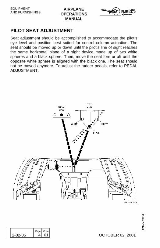
ATTENDANT’S CONTROL PANELS
The Forward Attendant Control Panel is located on the passengercabin divider opposite the forward attendant seat, in the entry area.This panel provides controls and indications for some functions of theLighting System, Air Conditioning temperature control, Attendant CallSystem and Passenger Service Unit (PSU).
The Aft Attendant Call Panel is located on the left face of the lavatorywall and consists of four attendant call indication lights.

EQUIPMENTAND FURNISHINGS
AIRPLANEOPERATIONS
MANUAL
2-02-15 Page
2 Code
01 OCTOBER 02, 2001
FORWARD ATTENDANT CONTROL PANEL (OPTION 1)
1 - ATTENDANT CALL INDICATION LIGHTSLAV (Amber) - Illuminates when the call is from the lavatory.PA (Green) - Illuminates when the call is from the passenger cabin.
2 - PSU TEST BUTTON− When pressed, provides PSU test, illuminating all the PSU’s
reading lights and attendant call lights. The associated attendantcall chimes are also activated.
3 - PSU RESET BUTTON− When pressed after test, allows resetting all PSUs to the initial
state.
4 - CALL RESET BUTTON− When pressed, clears all attendant call signals.
AFT ATTENDANT CALL PANEL
1 - ATTENDANT CALL INDICATION LIGHTSLAV (Amber) - Illuminates when the call is from the lavatory.PA (Green) - Illuminates when the call is from the passenger cabin.PILOT (Green) - Illuminates when the call is from the cockpit.PILOT EMERG (Red) - Illuminates when an emergency call to the
attendant is from the cockpit.

AIRPLANEOPERATIONS
MANUAL
EQUIPMENTAND FURNISHINGS
OCTOBER 02, 2001 2-02-15 Page
3 Code
01
FORWARD ATTENDANT CONTROL PANEL (OPTION 1)
AFT ATTENDANT CALL PANEL

EQUIPMENTAND FURNISHINGS
AIRPLANEOPERATIONS
MANUAL
2-02-15 Page
4 Code
01 OCTOBER 02, 2001
FORWARD ATTENDANT CONTROL PANEL (OPTION 2)
1 - ATTENDANT CALL INDICATION LIGHTSLAV (Red) - Illuminates when the call is from the lavatory.PAX (Amber) - Illuminates when the call is from the passenger cabin.
2 - PSU TEST BUTTON− When pressed, provides PSU test, illuminating all the PSU’s
reading lights and attendant call lights. The associated attendantcall chimes are also activated.
3 - PSU RESET BUTTON− When pressed after test, allows reseting all PSUs to the initial
state.
4 - CALL RESET BUTTON− When pressed, clears all attendant call signals.
AFT ATTENDANT CALL PANEL
1 - ATTENDANT CALL INDICATION LIGHTSLAV (Red) - Illuminates when the call is from the lavatory.PAX (Amber) - Illuminates when the call is from the passenger cabin.PILOT (Green) - Illuminates when the call is from the cockpit.PILOT EMERG (Red) - Illuminates when an emergency call to the
attendant is from the cockpit.
AIRPLANEOPERATIONS
MANUAL
EQUIPMENTAND FURNISHINGS
OCTOBER 02, 2001 2-02-15 Page
5 Code
01
FORWARD ATTENDANT CONTROL PANEL (OPTION 2)
AFT ATTENDANT CALL PANEL

EQUIPMENTAND FURNISHINGS
AIRPLANEOPERATIONS
MANUAL
2-02-15 Page
6 Code
01 OCTOBER 02, 2001
FORWARD ATTENDANT CONTROL PANEL (OPTION 3)
1 - ATTENDANT CALL INDICATION LIGHTSLAV (Red) - Illuminates when the call is from the lavatory.PAX (Amber) - Illuminates when the call is from the passenger cabin.
2 - PSU TEST BUTTON− When pressed, provides PSU test, illuminating all the PSU’s
reading lights and attendant call lights. The associated attendantcall chimes are also activated.
3 - PSU RESET BUTTON− When pressed after test, allows reseting all PSUs to the initial
state.
4 - CALL RESET BUTTON− When pressed, clears all attendant call signals.
AFT ATTENDANT CALL PANEL
1 - ATTENDANT CALL INDICATION LIGHTSLAV (Red) - Illuminates when the call is from the lavatory.PAX (Amber) - Illuminates when the call is from the passenger cabin.PILOT (Green) - Illuminates when the call is from the cockpit.PILOT EMERG (Red) - Illuminates when an emergency call to the
attendant is from the cockpit.

AIRPLANEOPERATIONS
MANUAL
EQUIPMENTAND FURNISHINGS
OCTOBER 02, 2001 2-02-15 Page
7 Code
01
FORWARD ATTENDANT CONTROL PANEL (OPTION 3)
AFT ATTENDANT CALL PANEL

EQUIPMENTAND FURNISHINGS
AIRPLANEOPERATIONS
MANUAL
2-02-15 Page
8 Code
01 OCTOBER 02, 2001
FORWARD ATTENDANT CONTROL PANEL (OPTION 4)
1 - ATTENDANT CALL INDICATION LIGHTSLAV (Red) - Illuminates when the call is from the lavatory.PAX (Amber) - Illuminates when the call is from the passenger cabin.
2 - PSU TEST BUTTON− When pressed, provides PSU test, illuminating all the PSU’s
reading lights and attendant call lights. The associated attendantcall chimes are also activated.
3 - PSU RESET BUTTON− When pressed after test, allows reseting all PSUs to the initial
state.
4 - CALL RESET BUTTON− When pressed, clears all attendant call signals.
AFT ATTENDANT CALL PANEL
1 - ATTENDANT CALL INDICATION LIGHTSLAV (Red) - Illuminates when the call is from the lavatory.PAX (Amber) - Illuminates when the call is from the passenger cabin.PILOT (Green) - Illuminates when the call is from the cockpit.PILOT EMERG (Red) - Illuminates when an emergency call to the
attendant is from the cockpit.

AIRPLANEOPERATIONS
MANUAL
EQUIPMENTAND FURNISHINGS
OCTOBER 02, 2001 2-02-15 Page
9 Code
01
FORWARD ATTENDANT CONTROL PANEL (OPTION 4)
AFT ATTENDANT CALL PANEL

EQUIPMENTAND FURNISHINGS
AIRPLANEOPERATIONS
MANUAL
2-02-15 Page
10 Code
01 OCTOBER 02, 2001
ENTRANCE PANELS
The Entrance Panels are located in the entry area, and provides maindoor control and indication and courtesy lights control.
NOTE: - The Interior Main Door Control Button is available only toairplanes equipped with Airstar door.

AIRPLANEOPERATIONS
MANUAL
EQUIPMENTAND FURNISHINGS
OCTOBER 02, 2001 2-02-20 Page
1 Code
01
GALLEY
The galley can be positioned in different locations of the forward areain passenger cabin.
The galley has many compartments that can be configured in differentways and can be equipped with different optional equipment tofacilitate and provide an appropriate flight service to the passengers.
The following items can equip the galley:
− Switches and Circuit Breaker Panel (Galley Control Panel);
− CD player;
− Toilet Smoke Detector Panel;
− Pre-Recorded Messages Control Panel;
− Half Trolleys;
− Waste Compartment;
− Ice Box;
− Hot Jugs;
− Pull-out Working Table;
− Stowage Compartment;
− Miscellaneous Compartment;
− Literature Pocket.

EQUIPMENTAND FURNISHINGS
AIRPLANEOPERATIONS
MANUAL
2-02-20 Page
2 Code
01 OCTOBER 02, 2001
GALLEY (STANDARD)

AIRPLANEOPERATIONS
MANUAL
EQUIPMENTAND FURNISHINGS
OCTOBER 02, 2001 2-02-20 Page
3 Code
01
CONTROLS AND INDICATORS
GALLEY CONTROL PANEL
1 - AREA LIGHTING BUTTON− When alternately pressed, turns on or off the galley area
lighting.
2 - AREA LIGHTING BRIGHT/DIM BUTTON− When alternately pressed, selects the bright or dim mode for
galley area lighting.
3 - LEFT AND RIGHT LIQUID CONTAINER BUTTON− When alternately pressed turns on or off heating for the
associated liquid container.− When the heating is turned on, the respective left or right
indication is lit.
GALLEY CONTROL PANEL

EQUIPMENTAND FURNISHINGS
AIRPLANEOPERATIONS
MANUAL
2-02-20 Page
4 Code
01 OCTOBER 02, 2001
THIS PAGE IS LEFT BLANK INTENTIONALLY

AIRPLANEOPERATIONS
MANUAL
EQUIPMENTAND FURNISHINGS
OCTOBER 02, 2001 2-02-25 Page
1 Code
01
PASSENGER SERVICE UNITThe Passenger Service Unit (PSU) provides the following services:
− Reading light with associated control button at each passenger seat.
− Passenger information sign informing the passenger of NO SMOKINGand FASTEN SEAT BELTS instructions.
− Pushbutton and indicator for attendant call.
− Air gasper for each individual passenger seat (refer to Section 2-14 –Pneumatics, Air Conditioning and Pressurization).
− Oxygen Masks Dispensing unit (refer to Section 2-16 – Oxygen).
− Loudspeaker for internal communication.

EQUIPMENTAND FURNISHINGS
AIRPLANEOPERATIONS
MANUAL
2-02-25 Page
2 Code
01 OCTOBER 02, 2001
CONTROLS AND INDICATORS
1 - ATTENDANT CALL INDICATOR LIGHT (amber)
− It also illuminates whenever the associated Attendant CallButton is pressed (attendant call is activated), for quickidentification of the passenger by the flight attendant.
2 - INDIVIDUAL READING LIGHT CONTROL BUTTON
− Turns on/off the associated individual reading light.
3 - ATTENDANT CALL BUTTON
− When pressed, it activates the attendant call.− When pressed again, it deactivates the attendant call.− When the attendant call is activated:
− An associated chime will be heard in all cabin loudspeakers.− The PA indication, located on the Attendant Control Panel,
will illuminate.− The associated zone attendant call annunciator will illuminate
to provide easy identification to the flight attendant. There arefour zone attendant call annunciators distributed in thepassenger cabin ceiling.
4 - NO SMOKING/FASTEN SEAT BELT SIGNS
− These passenger-warning signs are commanded by twoseparate switches, located on the Overhead Panel. Refer toSection 2-6 – Lighting.
− An associated chime, activated by the passenger addresssystem, will be heard whenever any passenger warning signs isturned on or off by the pilot.
− The signs may also be activated by the automatic oxygen relayactivation whenever sudden cabin depressurization occursabove 14000 ft cabin altitude.

AIRPLANEOPERATIONS
MANUAL
EQUIPMENTAND FURNISHINGS
OCTOBER 02, 2001 2-02-25 Page
3 Code
01
PASSENGER SERVICE UNIT

EQUIPMENTAND FURNISHINGS
AIRPLANEOPERATIONS
MANUAL
2-02-25 Page
4 Code
01 OCTOBER 02, 2001
THIS PAGE IS LEFT BLANK INTENTIONALLY

AIRPLANEOPERATIONS
MANUAL
EQUIPMENTAND FURNISHINGS
REVISION 27 2-02-30 Page
1 Code
01
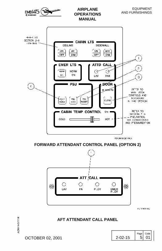
WATER AND WASTEWater service is provided to the washbasin for crew members andpassenger hygiene.
The waste system consists of a self-contained recirculating flushingtoilet.
WATER
The water supply consists of a tank, a faucet, drain valves andrequired tubing.
The faucet is installed on the washbasin and supplies water from thetank when the valve is pressed.
A lever beside the faucet actuates a valve to drain accumulatedwashbasin water into the atmosphere. Draining is performed by gravityon the ground or by differential pressure while in flight. A heater at theend of the drain line prevents its obstruction by ice formation. Theheater is activated whenever the DC BUS 1 is energized.
The wash basin drain line is also connected to the exterior by a mufflerproviding ventilation of the lavatory.
A water service control panel on the lower rear right side of the wing-to-fuselage fairing allows the supply of water to the tank and to drainingit, if necessary.
WASTE
The waste system consists of an electrically-operated self-containedrecirculation toilet unit, which collects and stores human waste in aninternal holding tank. Adequate chemical products are used to disinfectand deodorize the waste holding tank.
A vent line connecting the waste holding tank to the exterior performsits ventilation (odors exhaust) by means of differential pressure.
Toilet flushing is initiated by pressing and releasing the flush buttonadjacent to the toilet. This button actuates a motor-driven pump andfilter, which delivers flushing fluid for a pre-timed interval.
A restrictor at the bowl bottom prevents waste material return when it iscarried directly to the tank.
A waste service panel on the lower rear right side of the fuselage isequipped with a control cable, a waste drain valve and a rinse nipplewith cap, and allows the waste system to be serviced.

EQUIPMENTAND FURNISHINGS
AIRPLANEOPERATIONS
MANUAL
2-02-30 Page
2 Code
01 REVISION 27
WASTE AND WATER SYSTEM SCHEMATIC
AIRPLANEOPERATIONS
MANUAL
EQUIPMENTAND FURNISHINGS
OCTOBER 02, 2001 2-02-30 Page
3 Code
01
LAVATORY

EQUIPMENTAND FURNISHINGS
AIRPLANEOPERATIONS
MANUAL
2-02-30 Page
4 Code
01 OCTOBER 02, 2001
THIS PAGE IS LEFT BLANK INTENTIONALLY

AIRPLANEOPERATIONS
MANUAL
EQUIPMENTAND FURNISHINGS
REVISION 20 2-02-35 Page
1 Code
01
AIRSTAIR MAIN DOOR
The aircraft is provided with one main entry door located on the leftforward fuselage section.The main door, incorporating folding airstairs, is hinged at its loweredge. The door is raised in normal operation by two hydraulic dooractuators powered by hydraulic system 1 or by an accumulator withsufficient capacity for four complete door operation cycle.The door opening operation is manual. The hydraulic circuit dampingfunction allows a smooth operation when the door is lowered.The system may be controlled from inside or outside, through theentrance panel or through the exterior main door control panel,respectively.The door may also be closed and locked raising it manually, by anoutside ground attendant, and actuating either the inner or the outerhandle.An alternative opening valve is provided in the cockpit to allow themain door to be lowered if it is blocked by hydraulic system pressure(solenoid valve failure).
NOTE: No more than three persons should be standing on thedoorsteps simultaneously.
EICAS MESSAGE
TYPE MESSAGE MEANING
WARNING MAIN DOOR OPNMain door is open or not properlylocked either on the ground withengine 1 running or in flight.
EQUIPMENTAND FURNISHINGS
AIRPLANEOPERATIONS
MANUAL
2-02-35 Page
2 Code
01 REVISION 25
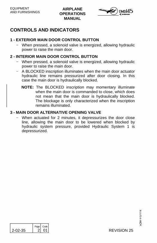
CONTROLS AND INDICATORS
1 - EXTERIOR MAIN DOOR CONTROL BUTTON− When pressed, a solenoid valve is energized, allowing hydraulic
power to raise the main door.
2 - INTERIOR MAIN DOOR CONTROL BUTTON− When pressed, a solenoid valve is energized, allowing hydraulic
power to raise the main door.− A BLOCKED inscription illuminates when the main door actuator
hydraulic line remains pressurized after door closing. In thiscase the main door is hydraulically blocked.
NOTE: The BLOCKED inscription may momentary illuminatewhen the main door is commanded to close, which doesnot mean that the main door is hydraulically blocked.The blockage is only characterized when the inscriptionremains illuminated.
3 - MAIN DOOR ALTERNATIVE OPENING VALVE− When actuated for 2 minutes, it depressurizes the door close
line, allowing the main door to be lowered when blocked byhydraulic system pressure, provided Hydraulic System 1 isdepressurized.

AIRPLANEOPERATIONS
MANUAL
EQUIPMENTAND FURNISHINGS
REVISION 20 2-02-35 Page
3 Code
01
AIRSTAIR MAIN DOOR CONTROLS AND INDICATORS
EQUIPMENTAND FURNISHINGS
AIRPLANEOPERATIONS
MANUAL
2-02-35 Page
4 Code
01 REVISION 29
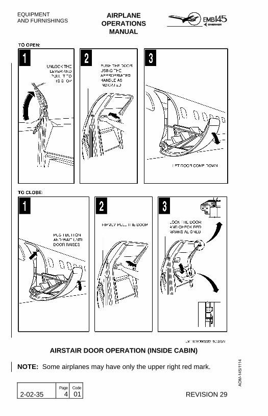
AIRSTAIR DOOR OPERATION (INSIDE CABIN)
NOTE: Some airplanes may have only the upper right red mark.
AIRPLANEOPERATIONS
MANUAL
EQUIPMENTAND FURNISHINGS
REVISION 20 2-02-35 Page
5 Code
01
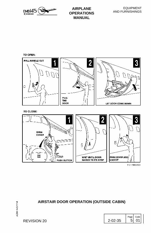
AIRSTAIR DOOR OPERATION (OUTSIDE CABIN)

EQUIPMENTAND FURNISHINGS
AIRPLANEOPERATIONS
MANUAL
2-02-35 Page
6 Code
01 REVISION 26
MAIN DOOR ACOUSTIC CURTAIN
The airplane is equipped with an acoustic curtain at the main doorarea. The acoustic curtain reduces noise level in the forwardpassenger cabin area when it is installed.
NOTE: - The acoustic curtain must be stowed for takeoff andlanding.
- The acoustic curtain should be installed during flights forpassenger comfort.
- The acoustic curtain should be rolled-up with the ultra-leather facing outward. Thus, in case of rain, snow, wind orother weather conditions, the ultra-leather will be theexposed material.

AIRPLANEOPERATIONS
MANUAL
EQUIPMENTAND FURNISHINGS
REVISION 26 2-02-35 Page
7 Code
01
MAIN DOOR ACOUSTIC CURTAIN
EQUIPMENTAND FURNISHINGS
AIRPLANEOPERATIONS
MANUAL
2-02-35 Page
8 Code
01 REVISION 26
THIS PAGE IS LEFT BLANK INTENTIONALLY

AIRPLANEOPERATIONS
MANUAL
EQUIPMENTAND FURNISHINGS
REVISION 20 2-02-40 Page
1 Code
01
ACCESS DOORS AND HATCHESThe aircraft is provided with one service door on the right side. Twopassenger cabin emergency escape hatches are located over thewings. Finally, a number of access doors and hatches for differentaircraft systems can be found along the fuselage.
SERVICE DOOR
The service door on the right side of the forward fuselage section isused for galley servicing and cabin cleaning between flights. It mayalso be used as an emergency exit.
The door is manually operated by internal and external handles. Openthe service door by lifting the handle and moving the door outward,followed by a forward rotation.
EICAS MESSAGE
TYPE MESSAGE MEANING
WARNING SERVICE DOOR OPN
Service door is open or notproperly locked either on theground with engine 1 running orin flight.

EQUIPMENTAND FURNISHINGS
AIRPLANEOPERATIONS
MANUAL
2-02-40 Page
2 Code
01 REVISION 29
SERVICE DOOR OPERATION
AIRPLANEOPERATIONS
MANUAL
EQUIPMENTAND FURNISHINGS
REVISION 30 2-02-40 Page
2A Code
01
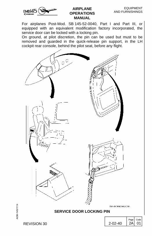
For airplanes Post-Mod. SB 145-52-0040, Part I and Part III, orequipped with an equivalent modification factory incorporated, theservice door can be locked with a locking pin.On ground, at pilot discretion, the pin can be used but must to beremoved and guarded in the quick-release pin support, in the LHcockpit rear console, behind the pilot seat, before any flight.
SERVICE DOOR LOCKING PIN

EQUIPMENTAND FURNISHINGS
AIRPLANEOPERATIONS
MANUAL
2-02-40 Page
2B Code
01 REVISION 30
THIS PAGE IS LEFT BLANK INTENTIONALLY

AIRPLANEOPERATIONS
MANUAL
EQUIPMENTAND FURNISHINGS
OCTOBER 02, 2001 2-02-40 Page
3 Code
01
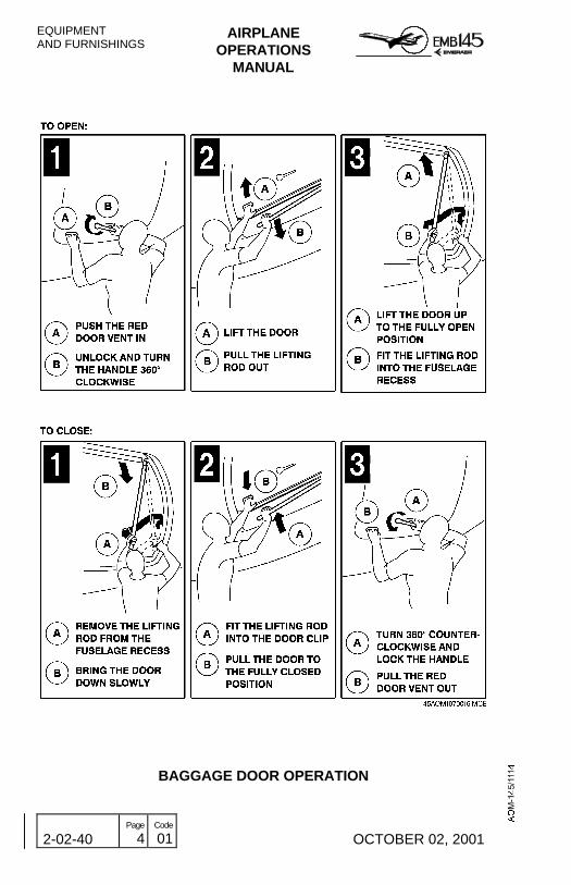
BAGGAGE DOOR
The baggage door on the rear left side of the fuselage is manuallyoperated from the outside. It is provided by a locking mechanismcontrolled by an external handle, stowed in the lower half of the door.The door is provided by depressurization vent that allows the openingoperation.
EICAS MESSAGE
TYPE MESSAGE MEANING
CAUTION BAGGAGE DOOR OPNBaggage door open or notproperly locked.
EQUIPMENTAND FURNISHINGS
AIRPLANEOPERATIONS
MANUAL
2-02-40 Page
4 Code
01 OCTOBER 02, 2001
BAGGAGE DOOR OPERATION
AIRPLANEOPERATIONS
MANUAL
EQUIPMENTAND FURNISHINGS
OCTOBER 02, 2001 2-02-40 Page
5 Code
01
COMPARTMENT HATCHES
A number of access doors and hatches for different aircraft systemscan be found along the fuselage.
The compartment hatches provide access for servicing the airplanesystems and equipment.
The under cockpit access hatch is located under the fuselage,providing access to the fuselage pressurized compartment.
The forward electronic compartment access hatch is inside the noselanding gear wheel well.
The rear electronic compartment access hatch is located on the rearright side of the fuselage. This hatch provides access to the airplanepressurized area containing the rear electronic compartment, rudderautopilot servo, rudder control cables and electrical harness, stabilizerelectrical harness and elevators control cables.
A unlocked condition of any compartment hatch causes a singlecaution message on EICAS. In addition, the MFD indicates the open-hatch(es) condition in a graphical representation.
EICAS MESSAGE
TYPE MESSAGE MEANING
CAUTION ACCESS DOORS OPNAt least one compartmentaccess hatch open or notproperly locked.
EQUIPMENTAND FURNISHINGS
AIRPLANEOPERATIONS
MANUAL
2-02-40 Page
6 Code
01 OCTOBER 02, 2001
REFUELING PANEL ACCESS DOOR
The refueling panel access door is located on the forward right side ofthe wing-to-fuselage fairing (refer to Section 2-8 – Fuel System).
The opening of the fueling panel access door causes a cautionmessage on EICAS. In addition, the MFD indicates the open-doorcondition in a graphical representation.
EICAS MESSAGE
TYPE MESSAGE MEANING
CAUTION FUELING DOOR OPNRefueling panel access dooropen or not properly closed.

AIRPLANEOPERATIONS
MANUAL
EQUIPMENTAND FURNISHINGS
REVISION 20 2-02-40 Page
7 Code
01
ACCESS DOORS AND HATCHES

EQUIPMENTAND FURNISHINGS
AIRPLANEOPERATIONS
MANUAL
2-02-40 Page
8 Code
01 REVISION 30
EMERGENCY EXIT HATCHES
Two passenger cabin emergency escape hatches are located over thewings. Refer to Section 1-10 – Emergency Information.
DOORS AND HATCHES INDICATION ON MFD
The DOORS section of the Takeoff System Page on MFD consists ofa graphical representation of the airplane (white) with squares locatedalong the fuselage to denote the various doors and hatches to bemonitored.
If a door or hatch is ajar, the associated graphical square will changefrom green to red and a red DOOR OPEN inscription will be presented,boxed in red, in the lower left corner of the DOORS section.
The following doors and hatches are monitored for status:
− Main door;
− Service door;
− Baggage door;
− Fueling panel access door;
− Rear electronic compartment access hatch;
− Forward electronic compartment access hatch;
− Under cockpit access hatch;
− Emergency exits hatches.

AIRPLANEOPERATIONS
MANUAL
EQUIPMENTAND FURNISHINGS
OCTOBER 02, 2001 2-02-40 Page
9 Code
01
DOORS AND HATCHES INDICATION ON MFD

EQUIPMENTAND FURNISHINGS
AIRPLANEOPERATIONS
MANUAL
2-02-40 Page
10 Code
01 OCTOBER 02, 2001
THIS PAGE IS LEFT BLANK INTENTIONALLY

AIRPLANEOPERATIONS
MANUAL
EQUIPMENTAND FURNISHINGS
REVISION 29 2-02-70 Page
1 Code
01
LAVATORY DOOR
For airplanes Post-Mod. SB 145-25-0287 or equipped with anequivalent modification factory incorporated, in case of slide doorjammed, there is an access box that can be used to unlock it.Remove the cover, and move the rod with the hand to up and downsimultaneously with the lavatory handle until the door open.

EQUIPMENTAND FURNISHINGS
AIRPLANEOPERATIONS
MANUAL
2-02-70 Page
2 Code
01 REVISION 29
LAVATORY DOOR WITH ACCESS BOX