Anti surge tank A.V.A.S.T. - Rensberg tanks/General catalogue AVAST... · The innovative antisurge...
14
Anti surge tank A.V.A.S.T.
Transcript of Anti surge tank A.V.A.S.T. - Rensberg tanks/General catalogue AVAST... · The innovative antisurge...

Anti surge tank
A.V.A.S.T.
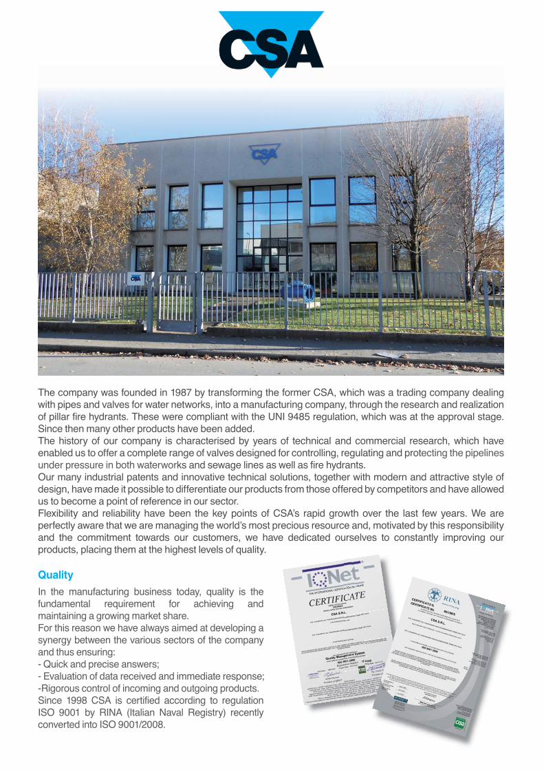
The company was founded in 1987 by transforming the former CSA, which was a trading company dealing
with pipes and valves for water networks, into a manufacturing company, through the research and realization
of pillar fire hydrants. These were compliant with the UNI 9485 regulation, which was at the approval stage.
Since then many other products have been added.
The history of our company is characterised by years of technical and commercial research, which have
enabled us to offer a complete range of valves designed for controlling, regulating and protecting the pipelines
under pressure in both waterworks and sewage lines as well as fire hydrants.
Our many industrial patents and innovative technical solutions, together with modern and attractive style of
design, have made it possible to differentiate our products from those offered by competitors and have allowed
us to become a point of reference in our sector.
Flexibility and reliability have been the key points of CSA’s rapid growth over the last few years. We are
perfectly aware that we are managing the world’s most precious resource and, motivated by this responsibility
and the commitment towards our customers, we have dedicated ourselves to constantly improving our
products, placing them at the highest levels of quality.
Quality
In the manufacturing business today, quality is the
fundamental requirement for achieving and
maintaining a growing market share.
For this reason we have always aimed at developing a
synergy between the various sectors of the company
and thus ensuring:
- Quick and precise answers;
- Evaluation of data received and immediate response;
-Rigorous control of incoming and outgoing products.
Since 1998 CSA is certified according to regulation
ISO 9001 by RINA (Italian Naval Registry) recently
converted into ISO 9001/2008.
3
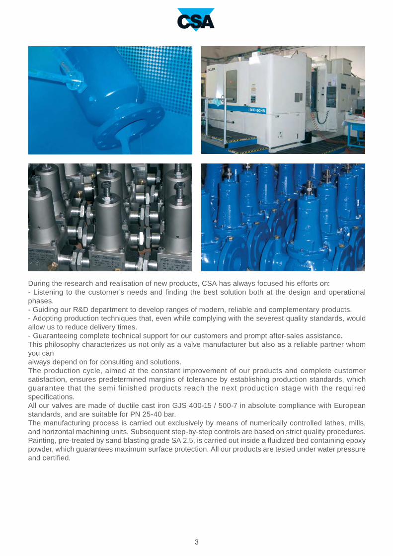
During the research and realisation of new products, CSA has always focused his efforts on:
- Listening to the customer’s needs and finding the best solution both at the design and operational
phases.
- Guiding our R&D department to develop ranges of modern, reliable and complementary products.
- Adopting production techniques that, even while complying with the severest quality standards, would
allow us to reduce delivery times.
- Guaranteeing complete technical support for our customers and prompt after-sales assistance.
This philosophy characterizes us not only as a valve manufacturer but also as a reliable partner whom
you can
always depend on for consulting and solutions.
The production cycle, aimed at the constant improvement of our products and complete customer
satisfaction, ensures predetermined margins of tolerance by establishing production standards, which
guarantee that the semi finished products reach the next production stage with the required
specifications.
All our valves are made of ductile cast iron GJS 400-15 / 500-7 in absolute compliance with European
standards, and are suitable for PN 25-40 bar.
The manufacturing process is carried out exclusively by means of numerically controlled lathes, mills,
and horizontal machining units. Subsequent step-by-step controls are based on strict quality procedures.
Painting, pre-treated by sand blasting grade SA 2.5, is carried out inside a fluidized bed containing epoxy
powder, which guarantees maximum surface protection. All our products are tested under water pressure
and certified.

Air vented anti surge tankA.V.A.S.T.
The innovative antisurge tank A.V.A.S.T. has been
designed to contain the devastating effects of water
hammer, more precisely the transients coming from the
sudden pump failure both for water and sewer systems.
The device, fully automatic, proved to be an innovative and
reliable solution thanks to the absence of air compressors,
electricity, panels, bladders, precharges. A.V.A.S.T. is the
ideal solution to avoid damages sometimes fatal for our
systems as a consequence of uncontrolled overpressures
and negative pressure waves.
Technical features and benefits
■ Designed for treated water and wastewater.
■ Available from 300 up to 25000 lt PN6/10/16.
■ Innovative system, pat. pending, to avoid bladders and compressors.
■ Low maintenance and reduced volumes compared to air vessels, bladders and tanks working with
precharges.
■ Anti-hammer device to control air outflow yet ensuring the maximum inflow during negative pressure
conditions.
■ Produced in different materials, welding in compliance with EN / ASME standards.
■ Supported by CSA transient analysis and calculation software.
Applications
■ To protect pumping station from negative and positive pressure conditions caused by pump failure and
used in:
■ Wastewater pressurized main lines.
■ Irrigation.
■ Water mains and distributions systems.

Pump failure
One of the most critical occurrence in water and wastewater system is the pump failure also called pump
trip. This definition means actually a full blackout, interrupting the pump’s head and causing a deceleration
with consequent negative pressure variation propagating with a speed whose value depends on the fluid
and pipe properties. Negative pressure is always a problem for possible pipe deformation, collapse,
gaskets movements and entrance of contaminated water and pollution through points of leakage. If the
hydraulic grade line, during the pump failure, drops to a negative value corresponding to the vapour
pressure there is the risk of column separation, generated by the formation and collapse of vapour pockets
producing serious and unexpected high frequency rises in pressure, sometimes fatal for the system.
The plot above shows a pipeline profile, with pumps and downstream tank as boundary conditions, where
the dark blue dotted line represents the HGL and the light blue dotted line is the static. The picture
represents the negative pressure wave propagating downstream as an effect of pump failure, where the
red segment depicts the area exposed to negative during the initial phase of the event.
Water hammer
The term water hammer is commonly used as a synonymous of unsteady flow, suggesting noise and fast
changing pressure variations sometimes related to devastating effects on the system.
Pipelines, both for water and sewage, are vital for our modern civilization and their safety and protection
should be one of the top priorities. During the studying and assessment of the pipeline network their
behaviour under transient conditions will reveal the potential for damages. This involves numerical
simulations carried out to reproduce events, planned or accidental, with consequences on the system.
The main causes of transients are :
-sudden changes in demand
-pump start up
-pump failure
-rapid closing and opening of isolation devices
-rapid filling of pipe line and fire fighting installations
-opening and closing fire hydrants
-pipe flushing and draining operations
-feed tanks draining
Water hammer can also be described as a propagation of energy, as in the transmission of sound, and
from basic physics as a wave motion the energy is associated with the elastic deformation of the medium.
The celerity of sound waves a in rigid pipes is given by
Where E is the modulus of elasticity;
D is the pipe diameter;
e is the wall thickness;
K is the bulk modulus;
ρ is the density of the fluid medium.
a=
Kρ
1+K DE e

1 2
3 4
The results of pump failure can be summarized in a plot showing the envelope of the maximum and
minimum pressure values reached during the simulation, in the picture above displayed in green and red.
It is evident how the system reaches a full vacuum on the entire profile and an extreme rise in pressure due
to the column separation, occurred at the change in slope.
The plot above shows the negative pressure wave propagating downstream the effect of pump failure. The
red segment depicts the area exposed to severe negative pressure. The change in slope represents a
location at risk of column separation, caused by vapour pockets forming and then collapsing creating
unwanted water hammer as explained on the 4 pictures.
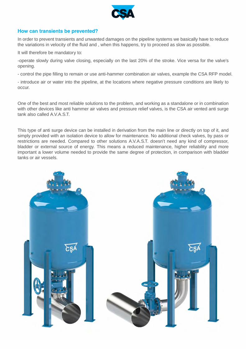
How can transients be prevented?
In order to prevent transients and unwanted damages on the pipeline systems we basically have to reduce
the variations in velocity of the fluid and , when this happens, try to proceed as slow as possible.
It will therefore be mandatory to:
-operate slowly during valve closing, especially on the last 20% of the stroke. Vice versa for the valve’s
opening.
- control the pipe filling to remain or use anti-hammer combination air valves, example the CSA RFP model.
- introduce air or water into the pipeline, at the locations where negative pressure conditions are likely to
occur.
One of the best and most reliable solutions to the problem, and working as a standalone or in combination
with other devices like anti hammer air valves and pressure relief valves, is the CSA air vented anti surge
tank also called A.V.A.S.T.
This type of anti surge device can be installed in derivation from the main line or directly on top of it, and
simply provided with an isolation device to allow for maintenance. No additional check valves, by pass or
restrictions are needed. Compared to other solutions A.V.A.S.T. doesn’t need any kind of compressor,
bladder or external source of energy. This means a reduced maintenance, higher reliability and more
important a lower volume needed to provide the same degree of protection, in comparison with bladder
tanks or air vessels.
1 2
3 4
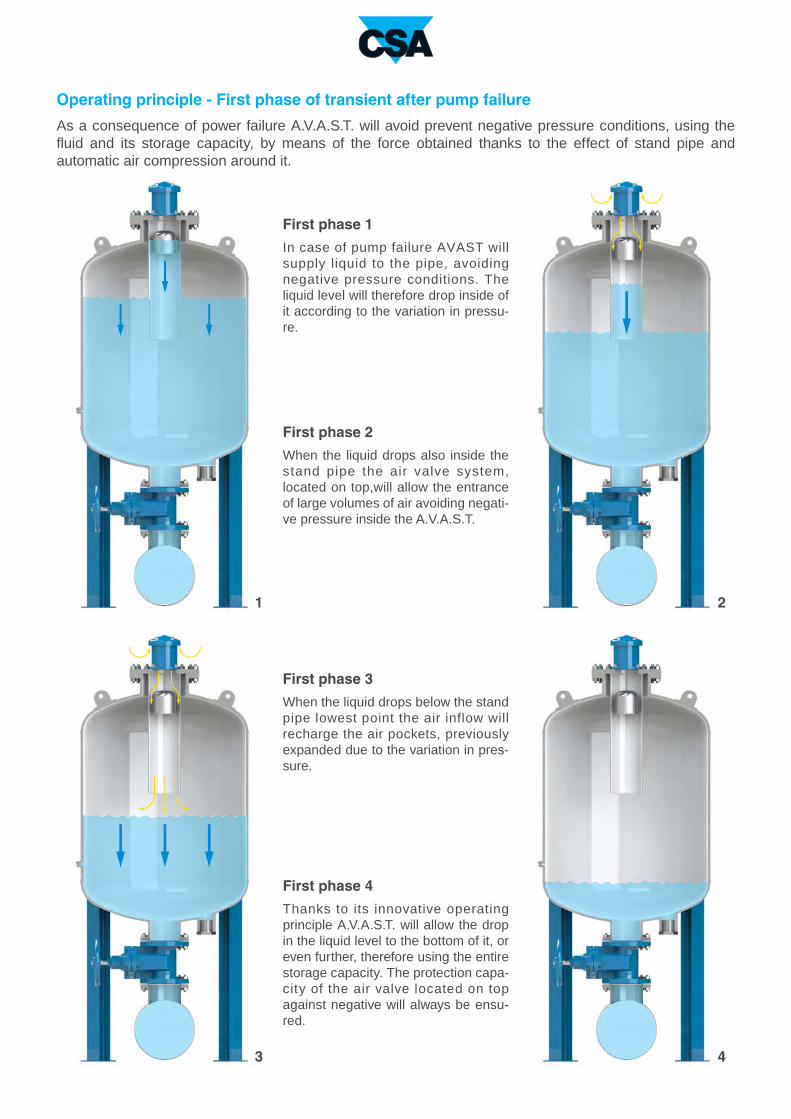
Operating principle - First phase of transient after pump failure
As a consequence of power failure A.V.A.S.T. will avoid prevent negative pressure conditions, using the
fluid and its storage capacity, by means of the force obtained thanks to the effect of stand pipe and
automatic air compression around it.
First phase 1
In case of pump failure AVAST will
supply liquid to the pipe, avoiding
negative pressure conditions. The
liquid level will therefore drop inside of
it according to the variation in pressu-
re.
First phase 2
When the liquid drops also inside the
stand pipe the air valve system,
located on top,will allow the entrance
of large volumes of air avoiding negati-
ve pressure inside the A.V.A.S.T.
First phase 3
When the liquid drops below the stand
pipe lowest point the air inflow will
recharge the air pockets, previously
expanded due to the variation in pres-
sure.
First phase 4
Thanks to its innovative operating
principle A.V.A.S.T. will allow the drop
in the liquid level to the bottom of it, or
even further, therefore using the entire
storage capacity. The protection capa-
city of the air valve located on top
against negative will always be ensu-
red.
1 2
3 4
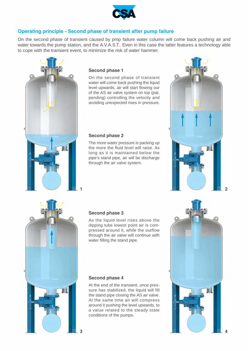
Operating principle - Second phase of transient after pump failure
On the second phase of transient caused by pmp failure water column will come back pushing air and
water towards the pump station, and the A.V.A.S.T.. Even in this case the latter features a technology able
to cope with the transient event, to minimize the risk of water hammer.
Second phase 1
On the second phase of transient
water will come back pushing the liquid
level upwards, air will start flowing our
of the AS air valve system on top (pat.
pending) controlling the velocity and
avoiding unexpected rises in pressure.
Second phase 2
The more water pressure is packing up
the more the fluid level will raise. As
long as it is maintained below the
pipe’s stand pipe, air will be discharge
through the air valve system.
Second phase 3
As the liquid level rises above the
dipping tube lowest point air is com-
pressed around it, while the outflow
through the air valve will continue with
water filling the stand pipe.
Second phase 4
At the end of the transient, once pres-
sure has stabilized, the liquid will fill
the stand pipe closing the AS air valve.
At the same time air will compress
around it pushing the level upwards, to
a value related to the steady state
conditions of the pumps.

The plot above shows the pressure envelope of the transient event caused by pump failure on a pipeline
with A.V.A.S.T. installed as a protection, in combination with anti-hammer air valves (CSA AS series). In this
case the effect of the air valve will help reducing the volume of A.V.A.S.T., containing budget and design
requirements. The red and green are the maximum and minimum pressure values reached during the
simulation. A.V.A.S.T. can be placed at the pumping station and/or along the profile and calculated to
perform with air valves and pressure relief valves, CSA VRCA series, if required.
The plot above shows the pressure envelope of the transient event caused by pump failure on a pipeline
with A.V.A.S.T. installed as a protection. The red and green are the maximum and minimum pressure
values reached during the simulation, it is clearly visible the beneficial effect in terms of negative pressure
and consequently water hammer reduction.
N.
1
2
3
4
5
6
7
8
9
10
7
10
4
8
5
6
9
3
1
2
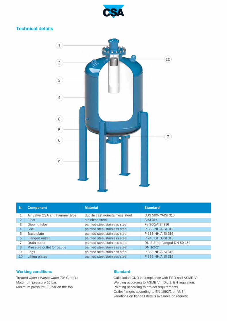
Technical details
Component
Air valve CSA anti hammer type
Float
Dipping tube
Shell
Base plate
Flanged outlet
Drain outlet
Pressure outlet for gauge
Legs
Lifting plates
Material
ductile cast iron/stainless steel
stainless steel
painted steel/stainless steel
painted steel/stainless steel
painted steel/stainless steel
painted steel/stainless steel
painted steel/stainless steel
painted steel/stainless steel
painted steel/stainless steel
painted steel/stainless steel
Standard
GJS 500-7/AISI 316
AISI 316
Fe 360/AISI 316
P 355 NH/AISI 316
P 355 NH/AISI 316
P 245 GH/AISI 316
DN 2-3” or flanged DN 50-150
DN 1/2-2”
P 355 NH/AISI 316
P 355 NH/AISI 316
Working conditions
Treated water / Waste water 70° C max.;
Maximum pressure 16 bar;
Minimum pressure 0,3 bar on the top.
Standard
Calculation CND in compliance with PED and ASME VIII.
Welding according to ASME VIII Div.1, EN regulation.
Painting according to project requirements.
Outlet flanges according to EN 1092/2 or ANSI;
variations on flanges details available on request.
30
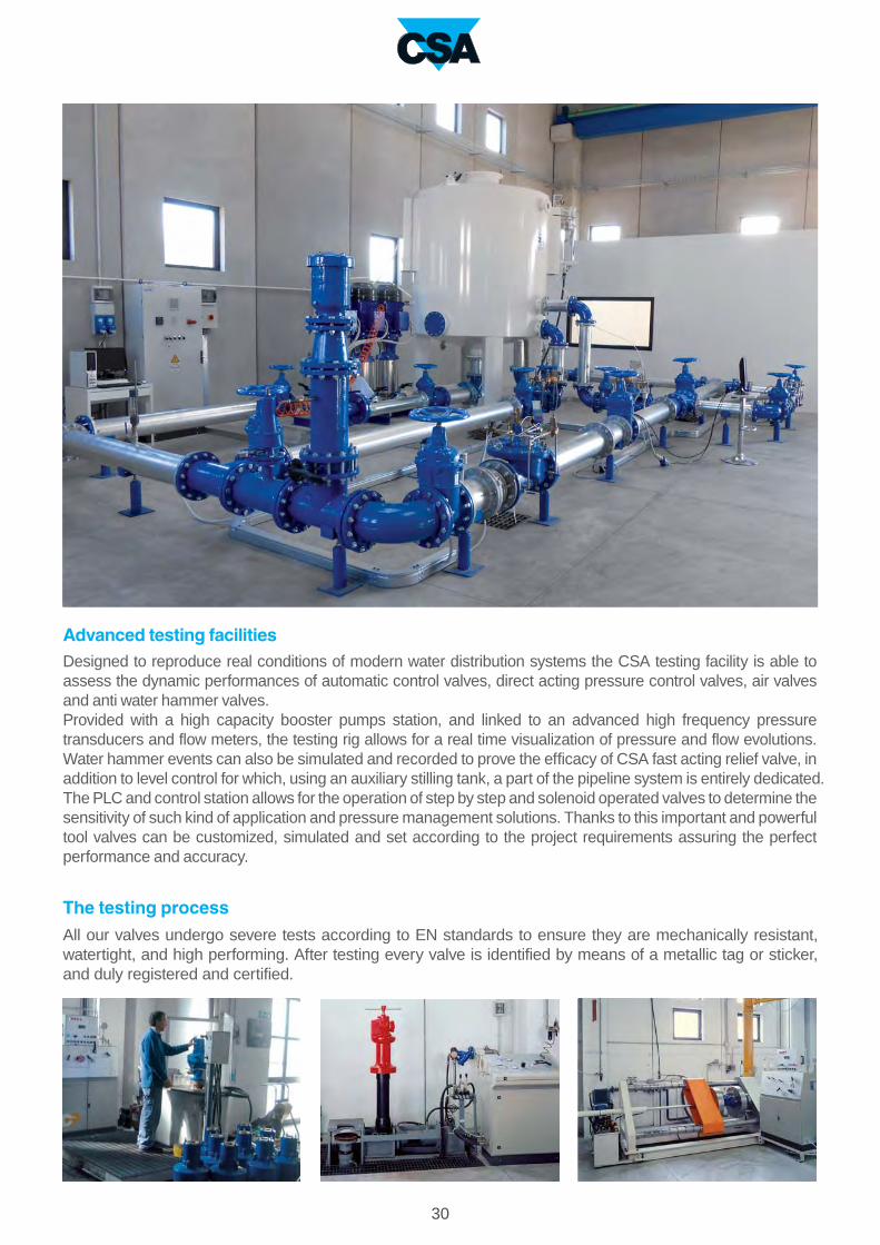
Designed to reproduce real conditions of modern water distribution systems the CSA testing facility is able to
assess the dynamic performances of automatic control valves, direct acting pressure control valves, air valves
and anti water hammer valves.
Provided with a high capacity booster pumps station, and linked to an advanced high frequency pressure
transducers and flow meters, the testing rig allows for a real time visualization of pressure and flow evolutions.
Water hammer events can also be simulated and recorded to prove the efficacy of CSA fast acting relief valve, in
addition to level control for which, using an auxiliary stilling tank, a part of the pipeline system is entirely dedicated.
The PLC and control station allows for the operation of step by step and solenoid operated valves to determine the
sensitivity of such kind of application and pressure management solutions. Thanks to this important and powerful
tool valves can be customized, simulated and set according to the project requirements assuring the perfect
performance and accuracy.
The testing process
All our valves undergo severe tests according to EN standards to ensure they are mechanically resistant,
watertight, and high performing. After testing every valve is identified by means of a metallic tag or sticker,
and duly registered and certified.
Advanced testing facilities

31
Water hammer analysisCSA Hyconsult
CSA Hyconsult was founded to provide
designers and consultants, involved in the
design of water distribution and sewage
systems, with accurate and unique technical
support.
CSA Hyconsult has specialized in hydraulic
modelling and transients analysis, entirely
through the use of modern computational tools
and advanced algorithms. Simulations are
essential to predict system responses to events
under a wide range of conditions without
disrupting the actual system.
Using simulations, problems can be anticipated
in possible or existing situations, and solutions
can be evaluated in order to invest time, money
and material in the most productive manner.
Research and innovation
CSA has always regarded knowledge as being
indispensable for the kind of research that
consistently feeds innovation at all levels. The
R&D department at CSA constantly strives to
improve product performance and continually
searches for new solutions to meet our
customer's needs. Twenty years of experience
in valve design and sizing, supported by
advanced computational tools, cooperation
with external entities at the highest level, and
test facilities for the verification of theoretical
results which are available for our customers,
guarantee our professionalism and reliability.

CSA s.r.l. - Strada San Giuseppe, 15 - località Ponteghiara
43039 Salsomaggiore Terme (PR) - Italy
TEL. +39.0524.523978 - FAX +39.0524.524031
www.csasrl.it - [email protected]

![[XLS]dep.ky.govdep.ky.gov/formslibrary/Documents/TankSpreadsheetv6a.xls · Web viewHints Glossary Tank#10 Tank#9 Tank#8 Tank#7 Tank#6 Tank#5 Tank#4 Tank#3 Tank#2 Tank#1 Summary Instructions](https://static.fdocuments.in/doc/165x107/5ab43ede7f8b9a1a048ba1de/xlsdepky-viewhints-glossary-tank10-tank9-tank8-tank7-tank6-tank5-tank4.jpg)